EP1568638B1 - Apparatus for bundling stacks of flat materials - Google Patents
Apparatus for bundling stacks of flat materials Download PDFInfo
- Publication number
- EP1568638B1 EP1568638B1 EP05100164A EP05100164A EP1568638B1 EP 1568638 B1 EP1568638 B1 EP 1568638B1 EP 05100164 A EP05100164 A EP 05100164A EP 05100164 A EP05100164 A EP 05100164A EP 1568638 B1 EP1568638 B1 EP 1568638B1
- Authority
- EP
- European Patent Office
- Prior art keywords
- stacking
- banding
- station
- stack
- band
- Prior art date
- Legal status (The legal status is an assumption and is not a legal conclusion. Google has not performed a legal analysis and makes no representation as to the accuracy of the status listed.)
- Expired - Lifetime
Links
- 238000003466 welding Methods 0.000 claims description 16
- 230000002441 reversible effect Effects 0.000 claims description 2
- 238000002347 injection Methods 0.000 claims 2
- 239000007924 injection Substances 0.000 claims 2
- 238000000034 method Methods 0.000 description 5
- 230000015572 biosynthetic process Effects 0.000 description 3
- 238000007664 blowing Methods 0.000 description 3
- 238000013461 design Methods 0.000 description 3
- 238000003780 insertion Methods 0.000 description 3
- 230000037431 insertion Effects 0.000 description 3
- 238000012546 transfer Methods 0.000 description 2
- 238000011144 upstream manufacturing Methods 0.000 description 2
- 238000009825 accumulation Methods 0.000 description 1
- 230000000454 anti-cipatory effect Effects 0.000 description 1
- 125000004122 cyclic group Chemical group 0.000 description 1
- 238000011161 development Methods 0.000 description 1
Images


Classifications
-
- B—PERFORMING OPERATIONS; TRANSPORTING
- B65—CONVEYING; PACKING; STORING; HANDLING THIN OR FILAMENTARY MATERIAL
- B65H—HANDLING THIN OR FILAMENTARY MATERIAL, e.g. SHEETS, WEBS, CABLES
- B65H33/00—Forming counted batches in delivery pile or stream of articles
- B65H33/16—Forming counted batches in delivery pile or stream of articles by depositing articles in batches on moving supports
- B65H33/18—Forming counted batches in delivery pile or stream of articles by depositing articles in batches on moving supports with separators between adjacent batches
-
- B—PERFORMING OPERATIONS; TRANSPORTING
- B65—CONVEYING; PACKING; STORING; HANDLING THIN OR FILAMENTARY MATERIAL
- B65B—MACHINES, APPARATUS OR DEVICES FOR, OR METHODS OF, PACKAGING ARTICLES OR MATERIALS; UNPACKING
- B65B13/00—Bundling articles
- B65B13/02—Applying and securing binding material around articles or groups of articles, e.g. using strings, wires, strips, bands or tapes
- B65B13/04—Applying and securing binding material around articles or groups of articles, e.g. using strings, wires, strips, bands or tapes with means for guiding the binding material around the articles prior to severing from supply
-
- B—PERFORMING OPERATIONS; TRANSPORTING
- B65—CONVEYING; PACKING; STORING; HANDLING THIN OR FILAMENTARY MATERIAL
- B65B—MACHINES, APPARATUS OR DEVICES FOR, OR METHODS OF, PACKAGING ARTICLES OR MATERIALS; UNPACKING
- B65B13/00—Bundling articles
- B65B13/18—Details of, or auxiliary devices used in, bundling machines or bundling tools
- B65B13/24—Securing ends of binding material
- B65B13/32—Securing ends of binding material by welding, soldering, or heat-sealing; by applying adhesive
-
- B—PERFORMING OPERATIONS; TRANSPORTING
- B65—CONVEYING; PACKING; STORING; HANDLING THIN OR FILAMENTARY MATERIAL
- B65B—MACHINES, APPARATUS OR DEVICES FOR, OR METHODS OF, PACKAGING ARTICLES OR MATERIALS; UNPACKING
- B65B27/00—Bundling particular articles presenting special problems using string, wire, or narrow tape or band; Baling fibrous material, e.g. peat, not otherwise provided for
- B65B27/08—Bundling paper sheets, envelopes, bags, newspapers, or other thin flat articles
-
- B—PERFORMING OPERATIONS; TRANSPORTING
- B65—CONVEYING; PACKING; STORING; HANDLING THIN OR FILAMENTARY MATERIAL
- B65H—HANDLING THIN OR FILAMENTARY MATERIAL, e.g. SHEETS, WEBS, CABLES
- B65H2404/00—Parts for transporting or guiding the handled material
- B65H2404/30—Chains
- B65H2404/31—Chains with auxiliary handling means
- B65H2404/312—Pockets, containers
Definitions
- One out EP 0 640 529 B1 known device for banding of stacks of flat workpieces comprises a fixed stacking shaft with a raised and lowered shaft bottom, a the stacking shaft with copies of printed products filling belt conveyor, one before and behind the stacking shaft arranged tape supply roll whose bands in the stacking shaft and welded together thus are performed in one piece from the one tape supply roll on the shaft bottom to the other tape supply roll.
- the shaft bottom is lowered as the height of a pile building thereupon increases.
- the belt located with a portion below the stack and on the shaft bottom abuts a downstream with respect to the conveying direction of the belt conveyor and to an upstream facing end face of the building stack.
- a temporarily receiving the stacking tray supplied copies auxiliary support device is placed in the stack forming area and pushed the tape from the upstream facing and from the downstream facing end face of the stack forth by means of a welding punch so far over the top of the stack until this is strapped.
- two sections of the belt are in mutual contact under the action of a respective one of the welding dies and are welded together in this position by means of the welding dies.
- a now present two-ply welded portion of the tape is severed in such a way that the stack is strapped by means of a closed band and the remaining band in turn runs in one piece from one to the other band-supply roll.
- the auxiliary support device temporarily placed in the stacking area takes over the function of the shaft bottom and transfers the part of the next formed during said operations and received by the auxiliary support device to be formed stack and the underlying section of the tape back to the again positioned in its altitude shaft bottom.
- the known device needs to complete a banded stack a time that is composed of the time to stack a stack of a certain number of copies and the time for banding the stack.
- a shortened time is needed with a packet delivery system which the Applicant has sold under the type designation PAS 66.
- This has a stacking station, a banding station and provided with stacking shafts, cyclically conveying endless conveyor.
- a strip supply extends integrally (after welding) from a first to a second supply roll, and this in contrast to the EP 0 640 529 B1 known device in such a way that a unwound belt section extends in a direction perpendicular to the conveying plane of the endless conveyor plane.
- the invention has for its object to provide a device for banding of stacks of flat workpieces with an alternative tape guide and a cycle time, which exceeds the stacking time at most insignificant.
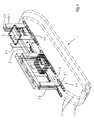
- the proposed device for banding flat workpieces 2 comprises an endless conveyor 1, which preferably has a first Switzerlandstofftown 1.1 and a second Switzerlandstoffschreib 1.2, in the present embodiment in the form of a first and a second pair of endless roller chains, with suitable sprockets 1.5 form a multiple chain drive.
- the two pairs of traction means 1.1 and 1.2 form a conveying section 1.3 from mutually parallel conveyor runs, which preferably lie in a single area and move in a cyclic manner in a direction indicated by the arrow 1.4 conveying direction.
- stacking shafts 2 are arranged along the same successive.
- a respectively trailing with respect to the conveying direction boundary of the stack shafts 2 is formed by rear stops 2.1 and 2.2 and a respective anticipatory limitation of the stacking shafts 2 of front stops 2.3 and 2.4.
- the rear stops 2.1 and 2.2 are attached to the first Werchutown 1.1, in such a way that they are transverse to the conveying direction and in the conveying direction preferably follow one another at equal intervals, which then determine the largest possible format of the stackable flat workpieces.
- the mutual position of the rear stops 2.1 with respect to the rear stops 2.2 is also adjustable by the mutual phase position of the traction means of the first pair of traction means 1.1.
- a respective stack 2 "built up in the stacking station P is supported by a support 2 '''formed by, for example, circumferential ribbons or fixed guides, which are spaced apart from each other transversely to the conveying direction 1.4 (see Figures 3 and 5 ).
- stacking shafts 2 are only then transported from the stacking station P into the banding station B, when in the stacking station P a stack 2 "is stacked, which has a certain number of flat workpieces 2 ', if subsequent accumulation of the flat workpieces 2 'temporarily intercepted and the stack has 2 "with its bottom contact with the endless conveyor. Such contact may be canceled during stacking when stack 2 ", as preferred provided on a raised and lowered stacking table 2 '''' (see Fig. 1 ) is piled up.
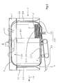
- the Fig. 3 With the omission of the endless conveyor 1, one of the stacking shafts 2 is in a position thereof in the banding station B again.
- the representation corresponds to a guided between the roller chains of the first Glasstoffpases 1.1 section in a transverse to the axes of the sprockets 1.5 (see Fig. 2 ) vertical plane and leaves among other things - as well as in Fig. 1 can be seen - recognize a formed on the stacking shafts 2 first banding guide 2.10 and arranged in the Banderolenstation B second banding guide 2.11, which is aligned substantially in or against the conveying direction.
- the first banding guide 2.10 comprises a first guide section 2.5 and a second guide section 2.6.
- first guide section 2.5 and a second guide section 2.6 are oriented substantially vertically and arranged such that in each case in the region of one and the same rear stop 2.1 and / or 2.2, a first guide section 2.5 and a second guide section 2.6, wherein the first guide section 2.5 pointing in the conveying direction according to arrow 1.4 and the second guide section 2.6 has a counter to the conveying direction facing guide surface.
- the guide surface pointing in the direction of conveyance is set back relative to a stop surface formed on the rear stops 2.1 and 2.2 for aligning the stack 2 ".
- the lower guide sections 2.7 and 2.8 and an upper guide section 2.9 having second band guide 2.11 forms together with the first band guide 2.10 a substantially closed guideway.
- a respective stack is 2 "by shooting a band portion of always the same length measured on conventional dimensions of the stack 2" strapped from the end portion of the belt 6 at first broadly.
- the said length is dimensioned such that the leading end of the inserted end section reaches a clamping, welding and cutting station 4 (see FIG Fig. 3 and 5 ).
- the shooting takes place by means of a reversible, the Banderolierstation B associated Einsch manvoretti 5, which in the present embodiment preferably a belt drive 5 'and cooperating with this Andrückrollen includes (see Fig. 3 and 5 ).
- the injected end portion is a free end of a wound up tape supply, not shown here.
- a Einsch manvorettivocardium which engages the tape 6, for example, under clamping between upper and lower bands of a tape drive assembly in the stacking shaft 2.
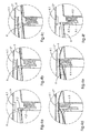
- FIGS. 4a to 4f show individual phases of the banding process and each represent the clamping, welding and cutting station 4. In this is for the banding process transverse to the conveying direction according to arrow 1.4 (see Fig. 1 and 3 ) below the support 2 '''anvil 4.1 inserted, which is withdrawn after completion of Banderoliervorganges again from the welding and cutting station 4.
- the said, always constant length of the shot end portion of the belt 6 is further dimensioned so that the leading end of the belt 6 extends at least substantially over the cross-sectional width of the anvil 4.1.
- the band 6 is guided through an opening 4.2 'in a plunger 4.2 (see Fig. 4b ), which applies the reaching under the anvil 4.1 leading end of the shot end portion of the belt 6 to the underside of the anvil 4.1 applies (see Fig. 4c ).
- the anvil 4.1 thus forms together with the plunger 4.2 a clamping device for the leading end of the shot end portion of the belt 6.
- the drive of the insertion device 5 is reversed and thus the stack 2 'initially broadly strapping band 6 tightened so that it conforms to the strapped surfaces of the stack 2 ".
- the plunger 4.2, the welding punch 4.3 and the blade 4.4 return to initial positions.
- the separated from the closed band 6 'free end of the tape stock remains for the next cycle in the opening 4.2' of the plunger 4.2.
- the Fig. 3 is a first alternative of the previously indicated and now explained arrangements again, which are made to safely secure a stack 2 "in the banding B with the injected into this end portion of the belt 6, although this much of this end portion above of the stack 2 "must be performed.
- This alternative provides for the formation of the already mentioned upper guide section 2.9 of the second band guide 2.11 a Pressure chamber 7 before. This forms with a substantially downwardly facing chamber wall 7.1 of the upper guide section 2.9.
- blowing nozzles 7.2 are provided from which operationally blowing air flows with a directional component, which points in the direction in which the injected end portion of the belt 6, the chamber wall 7.1 passes.
- the blast nozzles 7.2 are formed, for example, as slit nozzles and form in their entirety a floating nozzle arrangement 7.3, which holds the chamber wall 7.1 passing part of the injected portion of the belt 6 under the action of the aerodynamic paradox in a floating position against the chamber wall 7.1.
- a second alternative band guide 2.11 ' is provided, which forms an upper guide section 2.12 by means of a suction belt drive 8.1, which is located in a vacuum chamber
- the suction belt drive 8.1 comprises, for example, one or more perforated belts or a certain number of round belts which in each case form a conveying strand, which in the present case is the direction of entry of the Bandes 6 in the interior of the respective stacking shaft 2 operatively moved substantially in the conveying direction according to arrow 1.4.
- the arrangement of the perforated belts or round belts and the design of the insertion device 5 and optionally the welding and cutting station 4 and the first banding guide 2.10 depend on the number of the respective stacking shaft 2 supplied benefits.
- the arrangement of the blowing nozzles thereof may also be adapted to the number of uses supplied to the respective stacking shaft 2.
- the auxiliary stack carrier 9 is inserted manually or automatically between a last "flat piece 2" to be deposited on the stack 2 and a subsequent flat workpiece 2 'and temporarily stores the flat workpieces 2' to the last following (referred to in FIG Fig. 2 ) only hinted and incomplete reproduced endless conveyor 1 has spent the finished stack 2 "from the stacking station P in the banding station B, so that in the stacking station P is again an empty stacking shaft 2.
- auxiliary pile carrier 9 are again removed from the stack forming area and the accumulated on the auxiliary pile carrier 9 flat workpieces 2 'to the stacking table 2 "" (see Fig. 1 ) to hand over.
- the cycle time of the device set forth so far results essentially from the time required for stacking up a respective stack 2 ", for which only the time required for displacing a respective stacking shaft 2 from the stacking station P into the banding station B is obtained a certain number of flat workpieces 2 'per stack 2 ", namely, the time required for banding is shorter than that for stacking a respective stack 2".
- a stop 11 is provided for the leading edges of the flat workpieces 2 'conveyed into the stacking station P.
- the stop 11 comprises one or more such circumferential bands or belts that the descending edges of the flat workpieces 2 'downwardly moved dreams facing.
- the stop 11 is adjustable to the format of the supplied flat workpieces 2 'and for this purpose, for example by means of a chain 11.1 adjustable.
- the circulating as shown bands or belts of the stop 11 support advantageously the lowering of the arriving in the stacking station P flat workpieces 2 '.
Landscapes
- Engineering & Computer Science (AREA)
- Mechanical Engineering (AREA)
- Basic Packing Technique (AREA)
Abstract
Description
Eine aus
Während des Umreifens des die vorgesehene Höhe aufweisenden Stapels, des Verschweißens der Banderole und des Entfernes des banderolierten Stapels vom Schachtboden übernimmt die vorübergehend in den Stapelbildungsbereich verbrachte Hilfstragvorrichtung die Funktion des Schachtbodens und übergibt den während der genannten Vorgänge gebildeten und von der Hilfstragvorrichtung aufgenommenen Teil des nächsten zu bildenden Stapels und den darunter befindlichen Abschnitt des Bandes wieder an den erneut in seiner Höhenlage positionierten Schachtboden.During the strapping of the stack provided with the intended height, the welding of the banderole and the removal of the strapped stack from the shaft bottom, the auxiliary support device temporarily placed in the stacking area takes over the function of the shaft bottom and transfers the part of the next formed during said operations and received by the auxiliary support device to be formed stack and the underlying section of the tape back to the again positioned in its altitude shaft bottom.
Es ist eine gewisse Zeit erforderlich, um die genannte Hilfstragvorrichtung in den Stapelbildungsbereich zu verbringen. Die während dieser Zeit anfallenden flächigen Werkstücke werden bei der bekannten Vorrichtung vorübergehend auf dem genannten Bandförderer aufgestaut.It takes some time to transfer the said auxiliary support device into the stack formation area. The resulting during this time flat workpieces are temporarily dammed in the known device on said belt conveyor.
Die bekannte Vorrichtung benötigt zur Fertigstellung eines banderolierten Stapels eine Zeit, die sich zusammensetzt aus der Zeit zur Aufschichtung eines Stapels aus einer bestimmten Anzahl von Exemplaren und der Zeit zum Banderolieren des Stapels.The known device needs to complete a banded stack a time that is composed of the time to stack a stack of a certain number of copies and the time for banding the stack.
Eine demgegenüber verkürzte Zeit wird mit einem Päckchen-Auslegesystem benötigt, welches die Anmelderin unter der Typenbezeichnung PAS 66 vertrieben hat. Dieses weist eine Stapelstation, eine Banderolierstation und einen mit Stapelschächten versehenen, taktweise fördernden Endlosförderer auf. Ein Bandvorrat erstreckt sich einstückig (nach erfolgter Schweißung) von einer ersten zu einer zweiten Vorratsrolle, und dies im Gegensatz zu der aus
Der Erfindung liegt die Aufgabe zugrunde, eine Vorrichtung zum Banderolieren von Stapeln flächiger Werkstücke mit einer alternativen Bandführung und einer Taktzeit vorzusehen, welche die Stapelbildungsdauer höchstens unwesentlich übersteigt.The invention has for its object to provide a device for banding of stacks of flat workpieces with an alternative tape guide and a cycle time, which exceeds the stacking time at most insignificant.
Zur Lösung dieser Aufgabe ist eine Vorrichtung zur Bildung von Stapeln flächiger Werkstück und zum Banderolieren der Stapel mit einer Stapelstation, einer Banderolierstation und einem mit Stapelschächten versehenen, taktweise fördernden Endlosförderer ausgestattet mit einer jeweiligen, an einem jeweiligen der Stapelschächte ausgebildeten ersten Banderolenführung und einer in der Banderolierstation angeordneten zweiten Banderolenführung, die gemeinsam mit der jeweiligen ersten Banderolenführung eine im Wesentlichen in sich geschlossene Führungsbahn bildet.To solve this problem, a device for forming stacks of flat workpiece and for banding the stack with a stacking station, a banding station and a provided with stacking shafts, cyclically conveying endless conveyor equipped with a respective formed on a respective one of the stacking shafts first banding guide and in the Banderolierstation arranged second band guide, which forms a substantially self-contained guideway together with the respective first banding guide.
Mit einer dahingehenden Weiterbildung, dass ein vorübergehend zwischen zwei aufeinanderfolgende der flächigen Werkstücke über einen jeweiligen der Stapelschächte verbringbarer Hilfsstapelträger vorgesehen ist, wird eine Taktzeit erhalten, die im Wesentlichen auf die Stapelbildungszeit beschränkt ist.With a pertinent further development that a temporary auxiliary carrier which can be brought over a respective one of the stacking shafts is provided temporarily between two successive flat workpieces, a cycle time is obtained which is essentially limited to the stacking time.
Gleiches gilt auch für den Fall, dass stattdessen eine gewisse Anzahl der kontinuierlich anfallenden flächigen Werkstücke analog zur eingangs beschriebenen bekannten Vorrichtung vorübergehend auf einem die vorgeschlagene Vorrichtung mit diesen Werkstücken beschickenden Förderer aufgestaut werden.The same applies to the case that instead of a certain number of continuously accumulating flat workpieces are dammed analogously to the known device described above temporarily on a the device proposed with these workpieces feeding conveyor.
Die Merkmale des Erfindungsgegenstandes und Ausgestaltungen desselben sind den beigefügten Zeichnungen und den darauf Bezug nehmenden nachfolgenden Erläuterungen entnehmbar.The features of the subject invention and embodiments thereof can be taken from the accompanying drawings and the subsequent explanations taken to the following.
In den Zeichnungen zeigen:
- Fig. 1
- Stapelschächte, die aufeinanderfolgend an einem strichpunktiert angedeuteten, taktweise umlaufenden Endlosförderer angeordnet sind,
- Fig. 2
- in vereinfachter Darstellung einen Abschnitt des mit Stapelschächten ausgestatteten Endlosförderers, eine Antriebseinrichtung hierfür, eine Vorrichtung zur Beschickung eines Stapelschachtes in einer Stapelstation mit flächigen Werkstücken und eine einer Banderolierstation zugeordnete Einschießvorrichtung zum Einschießen eines Abschnittes eines Bandes in einen jeweiligen in der Banderolierstation befindlichen Stapelschacht,
- Fig. 3
- einen in der Banderolierstation befindlichen Stapelschacht, eine hierin ausgebildete erste Banderolenführung und eine ortsfeste zweite Banderolenführung, die gemeinsam mit der ersten eine in sich geschlossene Führungsbahn einer ersten Ausgestaltung bilden, und eine der Banderolierstation zugeordnete Schweiß- und Schneidstation,
- Fig. 4a bis 4f
- Momentanbilder aus dem Ablauf eines Banderoliervorganges,
- Fig. 5
- eine zweite Ausgestaltung einer in sich geschlossenen Führungsbahn.
- Fig. 1
- Stacking shafts, which are arranged successively at a dash-dotted line, cyclically rotating endless conveyor,
- Fig. 2
- in a simplified representation a portion of the endless conveyor equipped with stacking shafts, a drive device therefor, a device for feeding a stacking shaft in a stacking station with flat workpieces and a Einschießvorrichtung associated with a banding station for injecting a portion of a strip in a respective located in the banding stacking shaft,
- Fig. 3
- a stacking shaft located in the banding station, a first banding guide formed therein and a stationary second banding guide, which together with the first form a self-contained guide track of a first embodiment, and a welding and cutting station assigned to the banding station,
- Fig. 4a to 4f
- Instantaneous images from the course of a banding process,
- Fig. 5
- a second embodiment of a self-contained guideway.
Wie in
An dem Endlosförderer 1 sind entlang desselben aufeinanderfolgend Stapelschächte 2 angeordnet. Eine jeweils bezüglich der Förderrichtung nacheilende Begrenzung der Stapelschächte 2 wird von hinteren Anschlägen 2.1 und 2.2 und eine jeweils vorauseilende Begrenzung der Stapelschächte 2 von vorderen Anschlägen 2.3 und 2.4 gebildet. Die hinteren Anschläge 2.1 und 2.2 sind an dem ersten Zugmittelpaar 1.1 befestigt, und zwar so, dass sie sich quer zur Förderrichtung gegenüberstehen und in Förderrichtung bevorzugt unter gleichen Abständen aufeinanderfolgen, welche sodann das größt mögliche Format der stapelbaren flächigen Werkstücke bestimmen. Die gegenseitige Lage der hinteren Anschläge 2.1 bezüglich der hinteren Anschläge 2.2 ist auch durch die gegenseitige Phasenlage der Zugmittel des ersten Zugmittelpaares 1.1 einstellbar.At the endless conveyor 1
In analoger Weise sind die vorderen Anschläge 2.3 und 2.4 an dem zweiten Zugmittelpaar 1.2 befestigt.In an analogous manner, the front stops 2.3 and 2.4 are attached to the second Zugmittelpaar 1.2.
Durch Einstellung bestimmter gegenseitiger Phasenlagen einerseits des ersten und andererseits des zweiten Zugmittelpaares 1.1 und 1.2 sind die Stapelschächte 2 auf bestimmte Formate der flächigen Werkstücke 2' einstellbar. Mittels einer in
Es versteht sich, dass die Stapelschächte 2 erst dann von der Stapelstation P in die Banderolierstation B befördert werden, wenn in der Stapelstation P ein Stapel 2" aufgeschichtet ist, der eine bestimmte Anzahl von flächigen Werkstücken 2' aufweist, wenn danach anfallende der flächigen Werkstücke 2' vorübergehend abgefangen sind und der Stapel 2" mit seiner Unterseite Kontakt mit dem Endlosförderer hat. Ein solcher Kontakt kann während der Stapelbildung aufgehoben sein, wenn der Stapel 2", wie bevorzugt vorgesehen, auf einem heb- und senkbaren Stapeltisch 2'''' (siehe
Die
Die untere Führungsabschnitte 2.7 und 2.8 und einen oberen Führungsabschnitt 2.9 aufweisende zweite Banderolenführung 2.11 bildet gemeinsam mit der ersten Banderolenführung 2.10 eine im Wesentlichen geschlossene Führungsbahn. Insbesondere auch an dem oberen Führungsabschnitt 2.9 der Führungsbahn sind später näher erläuterte dahingehende Vorkehrungen getroffen, dass ein in der Banderolierstation B in einen Stapelschacht 2 eingeschossener Endabschnitt eines Bandes 6 sich zunächst an alle Führungsabschnitte 2.5 bis 2.9 anlegt. Insoweit wird ein jeweiliger Stapel 2" durch Einschießen eines Bandabschnittes von immer gleicher Länge gemessen an üblichen Dimensionen der Stapel 2" von dem Endabschnitt des Bandes 6 zunächst weiträumig umreift. Die genannte Länge ist so bemessen, dass das vorauseilende Ende des eingeschossenen Endabschnittes an eine Klemm-, Schweiß- und Schneidstation 4 gelangt (siehe
Der eingeschossene Endabschnitt ist ein freies Ende eines hier nicht dargestellten aufgewickelten Bandvorrates.The injected end portion is a free end of a wound up tape supply, not shown here.
Zum Einschießen läuft der Bandtrieb 5' bei vorliegendem Ausführungsbeispiel im Uhrzeigersinn um und das zwischen einem Fördertrum des Bandtriebes 5' und den genannten Andrückrollen befindliche Band 6 wird durch eine Lücke zwischen den unteren Führungsabschnitten 2.7 und 2.8 in den Innenraum des Stapelschachtes 2 eingeschossen. Dabei ist beim vorliegenden Ausführungsbeispiel die Eintrittsrichtung der Förderrichtung gemäß Pfeil 1.4 entgegengesetzt.For insertion of the tape drive 5 'runs in the present embodiment in a clockwise direction and located between a conveying strand of the belt drive 5' and the said
In alternativer Ausgestaltung ist eine Einschießvorrichtung vorgesehen, die das Band 6 beispielsweise unter Klemmung zwischen Ober- und Unterbändern einer Bandtriebanordnung in den Stapelschacht 2 einschießt.In an alternative embodiment, a Einschießvorrichtung is provided, which engages the
Die
Die genannte, immer gleich bleibende Länge des eingeschossenen Endabschnittes des Bandes 6 ist des Weiteren so bemessen, dass sich das vorauseilende Ende des Bandes 6 zumindest im Wesentlichen über die Querschnittbreite des Ambosses 4.1 erstreckt. Während des Einschießvorganges ist das Band 6 durch eine Öffnung 4.2' in einem Stößel 4.2 geführt (siehe
Nach erfolgter Klemmung des vorauseilenden Endes des eingeschossenen Endabschnittes des Bandes 6 wird der Antrieb der Einschießvorrichtung 5 reversiert und damit das den Stapel 2' zunächst weiträumig umreifende Band 6 derart gestrafft, dass es sich an die umreiften Oberflächen des Stapels 2" anschmiegt.After clamping the leading end of the shot end portion of the
Ist dieser Zustand erreicht, stoppt der reversierte Bandtrieb 5' und ein Schweißstempel 4.3 fährt in Richtung der Unterseite des Ambosses 4.1 und verschweißt nunmehr seitens des Schweißstempels 4.3 an den Amboss 4.1 angedrückte Abschnitte des Bandes 6 (siehe
Nach erfolgter Verschweißung der an den Amboss 4.1 angedrückten Abschnitte des Bandes 6 fährt ein Messer 4.4 in Richtung auf die Unterseite des Ambosses 4.1 und trennt eine nunmehr geschlossene, den Stapel 2" umschlingende Banderole 6' vom Bandvorrat ab (siehe
Ist dieser Vorgang abgeschlossen, so fahren der Stößel 4.2, der Schweißstempel 4.3 und das Messer 4.4 in Ausgangsstellungen zurück. Das von der geschlossenen Banderole 6' abgetrennte freie Ende des Bandvorrates verbleibt dabei für den nächsten Zyklus in der Öffnung 4.2' des Stößels 4.2.Once this process is completed, the plunger 4.2, the welding punch 4.3 and the blade 4.4 return to initial positions. The separated from the closed band 6 'free end of the tape stock remains for the next cycle in the opening 4.2' of the plunger 4.2.
Nach erfolgter Banderolierung wird des Weiteren der Amboss 4.1 wieder aus der Klemm-, Schweiß- und Schneidstation 4 abgezogen, ein nächster Stapel 2" durch vorübergehenden Antrieb des Endlosförderers 1 aus der Stapelstation P in die Banderolierstation B und der banderolierte Stapel 2' aus der Banderolierstation B in eine nachfolgende Station verschoben. Hiernach wird der Amboss 4.1 erneut in die Banderolierstation B eingeschoben, so dass sich ein Zustand gemäß
Die dargelegten Mittel und Abläufe zur Erstellung eines mit einer Banderole 6' versehenen Stapels 2" führen im Übrigen in vorteilhafter Weise dazu, dass die Banderolen 6' lediglich eine einzige Schweißnaht aufweisen.The stated means and procedures for creating a stack 2 'provided with a band 6', moreover, advantageously result in the bands 6 'having only a single weld seam.
Die
In
Die Anordnung der gelochten Bänder oder Rundriemen sowie die Ausgestaltung der Einschießvorrichtung 5 und gegebenenfalls der Schweiß- und Schneidstation 4 sowie der ersten Banderolenführung 2.10 richten sich dabei nach der Anzahl der dem jeweiligen Stapelschacht 2 zugeführten Nutzen.The arrangement of the perforated belts or round belts and the design of the
Für den Fall, dass die zweite Banderolenführung 2.11 die bereits genannte Schwebedüsenanordnung 7.3 umfasst, ist gegebenenfalls auch die Anordnung von deren Blasdüsen an die Anzahl der dem jeweiligen Stapelschacht 2 zugeführten Nutzen angepasst.In the event that the second banding guide 2.11 comprises the previously mentioned floating nozzle arrangement 7.3, the arrangement of the blowing nozzles thereof may also be adapted to the number of uses supplied to the respective stacking
Wie in
Der Hilfsstapelträger 9 wird je nach dessen Ausgestaltung manuell oder selbsttätig zwischen ein letztes auf dem Stapel 2" abzulegendes und ein darauf folgendes flaches Werkstück 2' eingeschoben und speichert vorübergehend die auf das genannte letzte folgenden flächigen Werkstücke 2' bis der hier (in
Nachdem dieser Zustand erreicht ist, werden der Hilfsstapelträger 9 wieder aus dem Stapelbildungsbereich entfernt und die auf dem Hilfsstapelträger 9 angesammelten flächigen Werkstücke 2' an den Stapeltisch 2"" (siehe
Ein ohne den Hilfsstapelträger 9 erforderlicher vorübergehender Rückstau der flächigen Werkstücke 2' auf der Zuführbandanordnung 10 kann somit vermieden werden.A temporary backflow of the flat workpieces 2 'on the
Die Taktzeit der insoweit dargelegten Vorrichtung ergibt sich im Wesentlichen aus der zur Aufschichtung eines jeweiligen Stapels 2" erforderlichen Zeit. Hierzu kommt lediglich die zur Verlagerung eines jeweiligen Stapelschachtes 2 von der Stapelstation P in die Banderolierstation B erforderliche Zeit. In aller Regel, d. h. ab einer bestimmten Anzahl flächiger Werkstücke 2' pro Stapel 2", ist nämlich die zum Banderolieren erforderliche Zeit kürzer als jene zur Aufschichtung eines jeweiligen Stapels 2".The cycle time of the device set forth so far results essentially from the time required for stacking up a
Wie in
Wie lediglich symbolhaft dargestellt, ist der Anschlag 11 auf das Format der angelieferten flächigen Werkstücke 2' einstellbar und hierzu beispielsweise mittels einer Kette 11.1 verstellbar.As shown only symbolically, the
Die wie dargelegt umlaufenden Bänder oder Riemen des Anschlags 11 unterstützen in vorteilhafter Weise das Absenken der in der Stapelstation P eintreffenden flächigen Werkstücke 2'.The circulating as shown bands or belts of the
Das Absenken der eingetroffenen flächigen Werkstücke 2' wird des Weiteren begünstigt durch ein an deren nachlaufenden Kante wirksames, ebenfalls abwärts bewegtes Trum der Zuführbandanordnung 10.The lowering of the arrived flat workpieces 2 'is further facilitated by an effective at the trailing edge, also moved down the run of the Zuführbandanordnung 10th
Claims (7)
- Device for forming stacks (2") of flat workpieces (2') and for banding the stacks (2"), including a stacking station (P) and a banding station (B) and an endless conveyor (1) that is provided with stacking shafts (2) and conveys in a cyclical manner,
characterized by
a respective first band guide (2.10) formed on a respective one of the stacking shafts (2) and by a second band guide (2.11; 2.11') that is arranged in the banding station (B) and form a substantially intrinsically closed guide path together with a respective first band guide (2.10). - Device according to Claim 1,
characterized by
a reversible injection device (5) that is associated with the banding station (B) and, during operation, injects an end section of a band (6) into a respective stacking shaft (2) present in the banding station. - Device according to Claim 2,
characterized by
a clamping, welding and cutting station (4) that is associated with the banding station (B) and into which the free end of the injected end section of the band 6 is clampable for the reversed operation of the injection device (5). - Device according to Claim 1,
characterized in
that the second band guide (2.11; 2.11') is substantially oriented in the conveying direction (arrow 1.4). - Device according to Claim 1,
characterized in
that the second band guide (2.11) comprises a floating nozzle configuration (7.3). - Device according to Claim 1,
characterized in
that the second band guide (2.11') comprises a suction belt drive (8.1). - Device according to at least one of claims 1 to 6,
characterized by
an auxiliary stack carrier (9) that is capable of being at least temporarily moved above a respective on of the stacking shafts (2).
Applications Claiming Priority (2)
| Application Number | Priority Date | Filing Date | Title |
|---|---|---|---|
| DE102004008469 | 2004-02-20 | ||
| DE102004008469A DE102004008469A1 (en) | 2004-02-20 | 2004-02-20 | Device for banding stacks of flat workpieces |
Publications (2)
| Publication Number | Publication Date |
|---|---|
| EP1568638A1 EP1568638A1 (en) | 2005-08-31 |
| EP1568638B1 true EP1568638B1 (en) | 2008-02-13 |
Family
ID=34745249
Family Applications (1)
| Application Number | Title | Priority Date | Filing Date |
|---|---|---|---|
| EP05100164A Expired - Lifetime EP1568638B1 (en) | 2004-02-20 | 2005-01-13 | Apparatus for bundling stacks of flat materials |
Country Status (5)
| Country | Link |
|---|---|
| US (1) | US7207161B2 (en) |
| EP (1) | EP1568638B1 (en) |
| AT (1) | ATE385983T1 (en) |
| DE (2) | DE102004008469A1 (en) |
| PT (1) | PT1568638E (en) |
Families Citing this family (11)
| Publication number | Priority date | Publication date | Assignee | Title |
|---|---|---|---|---|
| EP1571086A1 (en) * | 2004-03-05 | 2005-09-07 | Kba-Giori S.A. | Banding system for piled products and process |
| US20090169338A1 (en) * | 2007-12-28 | 2009-07-02 | Taiyo Seiki Co., Ltd. | Tape binding device |
| US8650836B2 (en) * | 2009-04-14 | 2014-02-18 | Illinois Tool Works Inc. | Film-tail sealing system and method for wrapping apparatus |
| DE102009040700A1 (en) * | 2009-09-10 | 2011-03-24 | Krones Ag | Method and device for the production of containers |
| ES2397264T3 (en) * | 2010-09-08 | 2013-03-05 | Titan Umreifungstechnik Gmbh & Co.Kg | Procedure for placing strips around packing pieces |
| DE102012223290A1 (en) * | 2012-12-14 | 2014-06-18 | Koenig & Bauer Aktiengesellschaft | Apparatus and method for banding stacks |
| JP6127686B2 (en) * | 2013-04-23 | 2017-05-17 | 沖電気工業株式会社 | Medium binding apparatus and medium arranging apparatus |
| CN104261181B (en) * | 2014-09-11 | 2016-11-09 | 德清中盈文具用品有限公司 | A kind of carton clout segregation apparatus |
| DE102015012484A1 (en) | 2015-09-24 | 2017-03-30 | Giesecke & Devrient Gmbh | Banding of banknotes |
| JP2025513903A (en) | 2022-04-15 | 2025-04-30 | シグノード インディア リミテッド | Systems and methods for wrapping coils - Patents.com |
| DE102024102734A1 (en) | 2024-01-31 | 2024-12-12 | Heidelberger Druckmaschinen Aktiengesellschaft | Feeder for a finishing machine for printed sheets and processes |
Family Cites Families (24)
| Publication number | Priority date | Publication date | Assignee | Title |
|---|---|---|---|---|
| US3213780A (en) * | 1964-01-31 | 1965-10-26 | Murray Co Texas Inc | Apparatus for banding bales |
| US3483817A (en) * | 1967-11-20 | 1969-12-16 | Anton R Stobb | Sheet stacker and bundler and method |
| DE1761434A1 (en) * | 1968-05-18 | 1971-06-09 | Demag Ag | Device for collecting, binding and transporting wire or strip-shaped rolled material |
| US3834297A (en) * | 1972-05-15 | 1974-09-10 | Signode Corp | Bale strapping system |
| JPS5137600B2 (en) * | 1973-05-24 | 1976-10-16 | ||
| DE2948237A1 (en) * | 1979-11-30 | 1981-06-04 | Hoechst Ag, 6000 Frankfurt | METHOD AND DEVICE FOR PRESSING, PACKING AND STRAPPING FIBROUS GOODS IN BALE SHAPE |
| EP0093953B1 (en) * | 1982-05-06 | 1988-05-11 | Vepa AG | Fibre baling press with a strapping device |
| US4625635A (en) * | 1985-02-19 | 1986-12-02 | Lewis Charles B | Banding apparatus for presses |
| JPS6367212A (en) * | 1986-08-29 | 1988-03-26 | 株式会社 サト− | Automatic packaging method and device |
| IT1253216B (en) * | 1991-10-21 | 1995-07-11 | Gd Spa | DEVICE FOR THE APPLICATION OF ADHESIVE BANDS TO PACKAGES |
| DE4328136A1 (en) * | 1993-08-24 | 1995-03-02 | Sesto Palamides | Device for banding copies of printed matter |
| NL9400112A (en) * | 1994-01-25 | 1995-09-01 | Vekamo B V | Device for applying a band of flexible material around at least one product. |
| US5379687A (en) * | 1994-02-04 | 1995-01-10 | Continental Eagle Corporation | Bale wire tie apparatus and method |
| AUPM388194A0 (en) * | 1994-02-14 | 1994-03-10 | John Lysaght (Australia) Limited | Wrapping apparatus with shuttle change |
| IT1279722B1 (en) * | 1995-08-24 | 1997-12-16 | Azionaria Costruzioni Acma Spa | METHOD AND UNIT FOR PACKAGING PRODUCTS |
| DE19615009B4 (en) * | 1996-04-16 | 2005-09-29 | Smb Schwede Maschinenbau Gmbh | Stacker with strapping device |
| DE19747040A1 (en) * | 1997-08-28 | 1999-03-04 | Heidelberger Druckmasch Ag | Air cushion guide |
| EP0899228B1 (en) | 1997-08-28 | 2004-04-14 | Heidelberger Druckmaschinen Aktiengesellschaft | Air cushion guiding device |
| US5890423A (en) * | 1998-04-01 | 1999-04-06 | Lih; Hui-O | Paper tape locating/guiding device of a bill tying machine |
| EP1053941B1 (en) * | 1999-04-10 | 2002-11-27 | ErgoPack Deutschland GmbH | Apparatus for strapping a palettised load |
| US6711883B2 (en) * | 1999-05-05 | 2004-03-30 | Smb Schwede Maschinenbau Gmbh | Strapping machine for strapping a stack of products |
| TW467098U (en) * | 2000-05-18 | 2001-12-01 | Strapack Corp | A lateral-type packing machine and an arch unit structure thereof |
| US6568158B2 (en) * | 2000-07-31 | 2003-05-27 | Strapack Corporation | Band-applying apparatus and method for use in packing system |
| DE10143839A1 (en) * | 2001-09-06 | 2003-03-27 | Bielomatik L O S Gmbh | Machine for banding book blocks comprises rectangular frame with oval central opening, strap being fed around it on surface of opening which is fitted with suction apertures |
-
2004
- 2004-02-20 DE DE102004008469A patent/DE102004008469A1/en not_active Withdrawn
-
2005
- 2005-01-13 AT AT05100164T patent/ATE385983T1/en not_active IP Right Cessation
- 2005-01-13 PT PT05100164T patent/PT1568638E/en unknown
- 2005-01-13 EP EP05100164A patent/EP1568638B1/en not_active Expired - Lifetime
- 2005-01-13 DE DE502005002786T patent/DE502005002786D1/en not_active Expired - Lifetime
- 2005-02-22 US US11/063,177 patent/US7207161B2/en not_active Expired - Fee Related
Also Published As
| Publication number | Publication date |
|---|---|
| EP1568638A1 (en) | 2005-08-31 |
| US20050183398A1 (en) | 2005-08-25 |
| DE102004008469A1 (en) | 2005-09-08 |
| PT1568638E (en) | 2008-05-13 |
| DE502005002786D1 (en) | 2008-03-27 |
| ATE385983T1 (en) | 2008-03-15 |
| US7207161B2 (en) | 2007-04-24 |
Similar Documents
| Publication | Publication Date | Title |
|---|---|---|
| DE3213561C2 (en) | ||
| DE69207356T2 (en) | Method and device for packaging bread | |
| DE60311785T2 (en) | Vertically oriented lateral transfer system for interfolded leaves | |
| DE3042519A1 (en) | DEVICE FOR STACKING PRODUCTS | |
| DE3348075C2 (en) | ||
| EP0968919B1 (en) | Method and device for enveloping quadrangular objects with a tape-like enveloping material | |
| EP1568638B1 (en) | Apparatus for bundling stacks of flat materials | |
| EP1184283A1 (en) | Method and device for tying stacks of printing products | |
| DE2311541A1 (en) | DEVICE FOR FORMING LOOSE PACKAGES OF PRE-DETERMINED NUMBER OF WORKPIECES FROM FLAT WORKPIECES | |
| DE2746670C2 (en) | Device for stacking bags | |
| DE4330427C2 (en) | Method and device for stacking flat goods, in particular for packaging biscuits | |
| DE19533086A1 (en) | Method and device for stacking flat products, in particular printed products | |
| EP1350750B1 (en) | Method and device for forming piles of continuously delivered, flat ojects | |
| DE2921605A1 (en) | BAG MAKING MACHINE | |
| EP0872443A2 (en) | Device for forming a partial stack being perpendicular to printed sheets piled on edge and side by side | |
| EP1439143A1 (en) | Method and device for forming stacks of printed products, comprising an additional sheet | |
| DE29917881U1 (en) | Strapping machine for strapping a stack of goods | |
| DE3505597A1 (en) | DEVICE FOR FORMING ROWS IN DISTANCE | |
| EP2311329B1 (en) | Feeding of rod-shaped articles from the tobacco processing industry | |
| DE3603484C2 (en) | ||
| DE3926966C2 (en) | ||
| EP0240691B1 (en) | Method for turning a continuous stream of paper sheets into packets | |
| DE2940924C2 (en) | ||
| EP1050463B1 (en) | Tying machine for tying a stack of articles | |
| DE19821918B4 (en) | Method for conveying products and handling unit for carrying out the method |
Legal Events
| Date | Code | Title | Description |
|---|---|---|---|
| PUAI | Public reference made under article 153(3) epc to a published international application that has entered the european phase |
Free format text: ORIGINAL CODE: 0009012 |
|
| AK | Designated contracting states |
Kind code of ref document: A1 Designated state(s): AT BE BG CH CY CZ DE DK EE ES FI FR GB GR HU IE IS IT LI LT LU MC NL PL PT RO SE SI SK TR |
|
| AX | Request for extension of the european patent |
Extension state: AL BA HR LV MK YU |
|
| 17P | Request for examination filed |
Effective date: 20060228 |
|
| AKX | Designation fees paid |
Designated state(s): AT BE BG CH CY CZ DE DK EE ES FI FR GB GR HU IE IS IT LI LT LU MC NL PL PT RO SE SI SK TR |
|
| GRAP | Despatch of communication of intention to grant a patent |
Free format text: ORIGINAL CODE: EPIDOSNIGR1 |
|
| RIN1 | Information on inventor provided before grant (corrected) |
Inventor name: BELMANN, MARKUS Inventor name: GANTER, UDO |
|
| GRAS | Grant fee paid |
Free format text: ORIGINAL CODE: EPIDOSNIGR3 |
|
| GRAA | (expected) grant |
Free format text: ORIGINAL CODE: 0009210 |
|
| AK | Designated contracting states |
Kind code of ref document: B1 Designated state(s): AT BE BG CH CY CZ DE DK EE ES FI FR GB GR HU IE IS IT LI LT LU MC NL PL PT RO SE SI SK TR |
|
| REG | Reference to a national code |
Ref country code: GB Ref legal event code: FG4D Free format text: NOT ENGLISH |
|
| REG | Reference to a national code |
Ref country code: CH Ref legal event code: EP |
|
| REG | Reference to a national code |
Ref country code: IE Ref legal event code: FG4D Free format text: LANGUAGE OF EP DOCUMENT: GERMAN |
|
| REF | Corresponds to: |
Ref document number: 502005002786 Country of ref document: DE Date of ref document: 20080327 Kind code of ref document: P |
|
| REG | Reference to a national code |
Ref country code: PT Ref legal event code: SC4A Free format text: AVAILABILITY OF NATIONAL TRANSLATION Effective date: 20080502 |
|
| PG25 | Lapsed in a contracting state [announced via postgrant information from national office to epo] |
Ref country code: IS Free format text: LAPSE BECAUSE OF FAILURE TO SUBMIT A TRANSLATION OF THE DESCRIPTION OR TO PAY THE FEE WITHIN THE PRESCRIBED TIME-LIMIT Effective date: 20080613 Ref country code: FI Free format text: LAPSE BECAUSE OF FAILURE TO SUBMIT A TRANSLATION OF THE DESCRIPTION OR TO PAY THE FEE WITHIN THE PRESCRIBED TIME-LIMIT Effective date: 20080213 Ref country code: ES Free format text: LAPSE BECAUSE OF FAILURE TO SUBMIT A TRANSLATION OF THE DESCRIPTION OR TO PAY THE FEE WITHIN THE PRESCRIBED TIME-LIMIT Effective date: 20080524 |
|
| NLV1 | Nl: lapsed or annulled due to failure to fulfill the requirements of art. 29p and 29m of the patents act | ||
| PG25 | Lapsed in a contracting state [announced via postgrant information from national office to epo] |
Ref country code: SI Free format text: LAPSE BECAUSE OF FAILURE TO SUBMIT A TRANSLATION OF THE DESCRIPTION OR TO PAY THE FEE WITHIN THE PRESCRIBED TIME-LIMIT Effective date: 20080213 Ref country code: PL Free format text: LAPSE BECAUSE OF FAILURE TO SUBMIT A TRANSLATION OF THE DESCRIPTION OR TO PAY THE FEE WITHIN THE PRESCRIBED TIME-LIMIT Effective date: 20080213 |
|
| REG | Reference to a national code |
Ref country code: IE Ref legal event code: FD4D |
|
| PG25 | Lapsed in a contracting state [announced via postgrant information from national office to epo] |
Ref country code: DK Free format text: LAPSE BECAUSE OF FAILURE TO SUBMIT A TRANSLATION OF THE DESCRIPTION OR TO PAY THE FEE WITHIN THE PRESCRIBED TIME-LIMIT Effective date: 20080213 Ref country code: SE Free format text: LAPSE BECAUSE OF FAILURE TO SUBMIT A TRANSLATION OF THE DESCRIPTION OR TO PAY THE FEE WITHIN THE PRESCRIBED TIME-LIMIT Effective date: 20080513 Ref country code: SK Free format text: LAPSE BECAUSE OF FAILURE TO SUBMIT A TRANSLATION OF THE DESCRIPTION OR TO PAY THE FEE WITHIN THE PRESCRIBED TIME-LIMIT Effective date: 20080213 Ref country code: IE Free format text: LAPSE BECAUSE OF FAILURE TO SUBMIT A TRANSLATION OF THE DESCRIPTION OR TO PAY THE FEE WITHIN THE PRESCRIBED TIME-LIMIT Effective date: 20080213 Ref country code: CZ Free format text: LAPSE BECAUSE OF FAILURE TO SUBMIT A TRANSLATION OF THE DESCRIPTION OR TO PAY THE FEE WITHIN THE PRESCRIBED TIME-LIMIT Effective date: 20080213 Ref country code: NL Free format text: LAPSE BECAUSE OF FAILURE TO SUBMIT A TRANSLATION OF THE DESCRIPTION OR TO PAY THE FEE WITHIN THE PRESCRIBED TIME-LIMIT Effective date: 20080213 |
|
| PG25 | Lapsed in a contracting state [announced via postgrant information from national office to epo] |
Ref country code: RO Free format text: LAPSE BECAUSE OF FAILURE TO SUBMIT A TRANSLATION OF THE DESCRIPTION OR TO PAY THE FEE WITHIN THE PRESCRIBED TIME-LIMIT Effective date: 20080213 |
|
| EN | Fr: translation not filed | ||
| PLBE | No opposition filed within time limit |
Free format text: ORIGINAL CODE: 0009261 |
|
| STAA | Information on the status of an ep patent application or granted ep patent |
Free format text: STATUS: NO OPPOSITION FILED WITHIN TIME LIMIT |
|
| 26N | No opposition filed |
Effective date: 20081114 |
|
| PG25 | Lapsed in a contracting state [announced via postgrant information from national office to epo] |
Ref country code: LT Free format text: LAPSE BECAUSE OF FAILURE TO SUBMIT A TRANSLATION OF THE DESCRIPTION OR TO PAY THE FEE WITHIN THE PRESCRIBED TIME-LIMIT Effective date: 20080213 |
|
| PG25 | Lapsed in a contracting state [announced via postgrant information from national office to epo] |
Ref country code: FR Free format text: LAPSE BECAUSE OF FAILURE TO SUBMIT A TRANSLATION OF THE DESCRIPTION OR TO PAY THE FEE WITHIN THE PRESCRIBED TIME-LIMIT Effective date: 20081205 Ref country code: EE Free format text: LAPSE BECAUSE OF FAILURE TO SUBMIT A TRANSLATION OF THE DESCRIPTION OR TO PAY THE FEE WITHIN THE PRESCRIBED TIME-LIMIT Effective date: 20080213 Ref country code: BG Free format text: LAPSE BECAUSE OF FAILURE TO SUBMIT A TRANSLATION OF THE DESCRIPTION OR TO PAY THE FEE WITHIN THE PRESCRIBED TIME-LIMIT Effective date: 20080513 |
|
| PG25 | Lapsed in a contracting state [announced via postgrant information from national office to epo] |
Ref country code: CY Free format text: LAPSE BECAUSE OF FAILURE TO SUBMIT A TRANSLATION OF THE DESCRIPTION OR TO PAY THE FEE WITHIN THE PRESCRIBED TIME-LIMIT Effective date: 20080213 |
|
| PG25 | Lapsed in a contracting state [announced via postgrant information from national office to epo] |
Ref country code: IT Free format text: LAPSE BECAUSE OF FAILURE TO SUBMIT A TRANSLATION OF THE DESCRIPTION OR TO PAY THE FEE WITHIN THE PRESCRIBED TIME-LIMIT Effective date: 20080213 Ref country code: MC Free format text: LAPSE BECAUSE OF NON-PAYMENT OF DUE FEES Effective date: 20090131 |
|
| GBPC | Gb: european patent ceased through non-payment of renewal fee |
Effective date: 20090113 |
|
| PG25 | Lapsed in a contracting state [announced via postgrant information from national office to epo] |
Ref country code: GB Free format text: LAPSE BECAUSE OF NON-PAYMENT OF DUE FEES Effective date: 20090113 |
|
| PG25 | Lapsed in a contracting state [announced via postgrant information from national office to epo] |
Ref country code: BE Free format text: LAPSE BECAUSE OF NON-PAYMENT OF DUE FEES Effective date: 20090131 |
|
| PG25 | Lapsed in a contracting state [announced via postgrant information from national office to epo] |
Ref country code: AT Free format text: LAPSE BECAUSE OF NON-PAYMENT OF DUE FEES Effective date: 20090113 |
|
| PG25 | Lapsed in a contracting state [announced via postgrant information from national office to epo] |
Ref country code: GR Free format text: LAPSE BECAUSE OF FAILURE TO SUBMIT A TRANSLATION OF THE DESCRIPTION OR TO PAY THE FEE WITHIN THE PRESCRIBED TIME-LIMIT Effective date: 20080514 |
|
| PGFP | Annual fee paid to national office [announced via postgrant information from national office to epo] |
Ref country code: PT Payment date: 20101221 Year of fee payment: 7 |
|
| PG25 | Lapsed in a contracting state [announced via postgrant information from national office to epo] |
Ref country code: LU Free format text: LAPSE BECAUSE OF NON-PAYMENT OF DUE FEES Effective date: 20090113 |
|
| PG25 | Lapsed in a contracting state [announced via postgrant information from national office to epo] |
Ref country code: HU Free format text: LAPSE BECAUSE OF FAILURE TO SUBMIT A TRANSLATION OF THE DESCRIPTION OR TO PAY THE FEE WITHIN THE PRESCRIBED TIME-LIMIT Effective date: 20080814 |
|
| PG25 | Lapsed in a contracting state [announced via postgrant information from national office to epo] |
Ref country code: TR Free format text: LAPSE BECAUSE OF FAILURE TO SUBMIT A TRANSLATION OF THE DESCRIPTION OR TO PAY THE FEE WITHIN THE PRESCRIBED TIME-LIMIT Effective date: 20080213 |
|
| REG | Reference to a national code |
Ref country code: PT Ref legal event code: MM4A Free format text: LAPSE DUE TO NON-PAYMENT OF FEES Effective date: 20120713 |
|
| PG25 | Lapsed in a contracting state [announced via postgrant information from national office to epo] |
Ref country code: PT Free format text: LAPSE BECAUSE OF NON-PAYMENT OF DUE FEES Effective date: 20120713 |
|
| PGFP | Annual fee paid to national office [announced via postgrant information from national office to epo] |
Ref country code: CH Payment date: 20140123 Year of fee payment: 10 Ref country code: DE Payment date: 20140131 Year of fee payment: 10 |
|
| REG | Reference to a national code |
Ref country code: DE Ref legal event code: R119 Ref document number: 502005002786 Country of ref document: DE |
|
| REG | Reference to a national code |
Ref country code: CH Ref legal event code: PL |
|
| PG25 | Lapsed in a contracting state [announced via postgrant information from national office to epo] |
Ref country code: LI Free format text: LAPSE BECAUSE OF NON-PAYMENT OF DUE FEES Effective date: 20150131 Ref country code: CH Free format text: LAPSE BECAUSE OF NON-PAYMENT OF DUE FEES Effective date: 20150131 Ref country code: DE Free format text: LAPSE BECAUSE OF NON-PAYMENT OF DUE FEES Effective date: 20150801 |