EP1568602B1 - Zusatzantriebsanlage durch Umlenkung des Fluidstroms - Google Patents
Zusatzantriebsanlage durch Umlenkung des Fluidstroms Download PDFInfo
- Publication number
- EP1568602B1 EP1568602B1 EP04004172A EP04004172A EP1568602B1 EP 1568602 B1 EP1568602 B1 EP 1568602B1 EP 04004172 A EP04004172 A EP 04004172A EP 04004172 A EP04004172 A EP 04004172A EP 1568602 B1 EP1568602 B1 EP 1568602B1
- Authority
- EP
- European Patent Office
- Prior art keywords
- channel
- use according
- propulsion
- takes place
- propulsion unit
- Prior art date
- Legal status (The legal status is an assumption and is not a legal conclusion. Google has not performed a legal analysis and makes no representation as to the accuracy of the status listed.)
- Expired - Lifetime
Links
Images


Classifications
-
- B—PERFORMING OPERATIONS; TRANSPORTING
- B63—SHIPS OR OTHER WATERBORNE VESSELS; RELATED EQUIPMENT
- B63H—MARINE PROPULSION OR STEERING
- B63H9/00—Marine propulsion provided directly by wind power
- B63H9/02—Marine propulsion provided directly by wind power using Magnus effect
-
- Y—GENERAL TAGGING OF NEW TECHNOLOGICAL DEVELOPMENTS; GENERAL TAGGING OF CROSS-SECTIONAL TECHNOLOGIES SPANNING OVER SEVERAL SECTIONS OF THE IPC; TECHNICAL SUBJECTS COVERED BY FORMER USPC CROSS-REFERENCE ART COLLECTIONS [XRACs] AND DIGESTS
- Y02—TECHNOLOGIES OR APPLICATIONS FOR MITIGATION OR ADAPTATION AGAINST CLIMATE CHANGE
- Y02T—CLIMATE CHANGE MITIGATION TECHNOLOGIES RELATED TO TRANSPORTATION
- Y02T70/00—Maritime or waterways transport
- Y02T70/50—Measures to reduce greenhouse gas emissions related to the propulsion system
- Y02T70/5218—Less carbon-intensive fuels, e.g. natural gas, biofuels
- Y02T70/5236—Renewable or hybrid-electric solutions
Definitions
- a disadvantage of this additional drive systems is that they can only generate propulsion in certain wind directions (up to 2 lines in the direction of travel).
- the rotating cylinder 20 is arranged transversely to the direction of travel in this variant and in a further variant, preferably equipped with end plates 70, to further enhance the effect of the Magnus effect.
- This figure shows in front view two types of air intake.
Landscapes
- Engineering & Computer Science (AREA)
- Sustainable Development (AREA)
- Sustainable Energy (AREA)
- Chemical & Material Sciences (AREA)
- Combustion & Propulsion (AREA)
- Mechanical Engineering (AREA)
- Ocean & Marine Engineering (AREA)
- Life Sciences & Earth Sciences (AREA)
- Wind Motors (AREA)
- Fluid-Pressure Circuits (AREA)
- Indicating Or Recording The Presence, Absence, Or Direction Of Movement (AREA)
- Pipe Accessories (AREA)
- Flow Control (AREA)
- Paper (AREA)
- External Artificial Organs (AREA)
- Other Liquid Machine Or Engine Such As Wave Power Use (AREA)
- Toys (AREA)
- Control Of Position, Course, Altitude, Or Attitude Of Moving Bodies (AREA)
- Earth Drilling (AREA)
- Preparation Of Compounds By Using Micro-Organisms (AREA)
- Motorcycle And Bicycle Frame (AREA)
- Massaging Devices (AREA)
- Structures Of Non-Positive Displacement Pumps (AREA)
Description
- Die Erfindung betrifft eine neue Verwendung einer auf der Grundlage des Magnus-Effekts arbeitende Antriebsanlage zu Zwecken eines Zusatzantriebs zu einem bestehenden Vortrieb.
- Es sind Windzusatzantriebsanlagen bekannt, welche auf dem Magnus-Effekt (Magnus, 1852) basieren, die hierzu weiteren physikalischen Grundlagen (Prantl, 1904) nutzen und in der Entwicklung des Flettner-Rotors (Flettner, 1922) ihre erste Realisierung erfuhren, vgl. auch GB-A 2 102 755 (Blohm & Voss) mit einem "Flettner-Rotor" für Schiffsantriebe.
- Praktische Umsetzung erfuhr der Flettner-Rotor auf der Grundlage von Versuchen der AVA, Göttingen (1922-1924) durch die Germania-Werft mit dem Umbau des Segelschiffes "Buckau" (1924) und der RMS "Barbara" (1926).
- Bei diesen Wind-Zusatzantriebsanlagen wird ein angetriebener, rotierender Kreiszylinder (Rotor) direkt vom Wind und Fahrtwind angeströmt; durch den Magnus-Effekt wird ein nicht unerheblicher Vortrieb erzeugt.
- Ein Nachteil dieser Zusatzantriebsanlagen ist, dass sie nur bei bestimmten Windrichtungen (bis zu 2 Strich in Fahrtrichtung) einen Vortrieb erzeugen können.
- Aus diesem Grund sind diese bekannten Zusatzantriebsanlagen für Fahrzeuge, welche sich relativ schnell bewegen, nicht einsetzbar, da bedingt durch den starken Fahrtwind die Gesamt-Windanströmung von im wesentlichen vorne erfolgt und somit außerhalb des Wirkungsbereiches liegt.
- Die Angabe der Erfindung ist eine Zusatzantriebsanlage, welche auch bei direkt von vorn auftreffendem Fluidstrom einen Vortrieb erzeugen kann.
- Das Fluid kann hierbei sowohl aus Luft, Gasen oder Flüssigkeiten bestehen. Für die Beschreibung wird ausschließlich auf den Luftstrom abgestellt; die Erfindung umfasst jedoch alle Arten von Fluidströmen (Anspruch 1,2).
- Die der Erfindung zugrundeliegende Idee ist die Umlenkung des von vorn auftreffenden Fahrtfluids auf einen rotierenden Zylinder zur Erzeugung eines Vortriebs auf der Grundlage des Magnus-Effekts.
- Die Verwendung umschreibt den Einfluss des von vorne in den Kanal eintretenden Fluids mit dessen Umlenkung, zur Weiterleitung auf den Magnus-Rotor, vertikal oder horizontal angeordnet (Anspruch 1, Anspruch 2).
- Spezielle Ausbildungen der Form des Kanals (Anspruch 10 bis 12) und der Ausrichtung der Umlenkung (Anspruch 3 bis 7) ermöglichen Anpassungen an die Anwendung, beispielsweise bei Landfahrzeugen, die relativ schnell bewegte Fahrzeuge sind, bei denen der Fahrwind (als Fluid) von im wesentlichen vorne anströmt. Der Fahrwind selbst wird durch den regulären Antrieb (Vortrieb) des Fahrzeugs (primär) erzeugt und ermöglicht damit die Ausnutzung dieses strömenden Fluids mit und von der mit Umlenkung versehenen Zusatz-Antriebsanlage. Eine Verlagerung des rotierenden Zylinders aus der Mitte des Kanals (Anspruch 8, Anspruch 9) ermöglicht eine Verstärkung dieses Effekts.
- GB-A 371,691 (Medvedeff) beschreibt ein Flugschiff, mit einem winklig ausgebildeten Kanal, in den drei Magnus-Rotoren, die elektrisch angetrieben werden, eingesetzt sind. Diese Rotoren liegen horizontal zur Ebene des Hauptschiffs und haben zusammen eine U-Form ausgebildet, wobei nur der mittlere Rotor für den Vortrieb in Längsrichtung des Luftschiffs sorgt. Durch seitlich vorhandene Öffnungen zu einem Kanal wird von mehreren Turbinen Luft angesaugt und den genannten Rotoren zugeführt, zur Erzeugung von Vortriebskraft aus dem genannten einen Rotor und zur Erzeugung von Hubkraft hinsichtlich der beiden anderen Rotoren. Eine Zusatz-Antriebsanlage ist hier nicht beschrieben.
- GB-A 2 256 410 (MacDuff) zeigt ein Wasserfahrzeug nach den dortigen Figuren 4 bis 6, auch anwendbar auf eine Schwimmplattform nach der dortigen Figur 11 oder ein Unterseeboot nach der dortigen Figur 12, wobei ein Wasserstrom in einem Wasserkanal ausgenutzt wird, der durch eine Pumpe im Kanal erzeugt wird. Diese Antriebsanlage sorgt für den Vortrieb des "Marinefahrzeugs" (als zusammenfassender Begriff zu den genannten einzelnen Objekten), ist aber nicht zusätzlich zu einer vorhandenen anderen Anlage ausgebildet, sondern die alleinige Hauptantriebsanlage für den Vortrieb des Marinefahrzeugs. Aus GB-A 494,093 (Gavrilov) sind einzelne nach dem Magnus-Prinzip arbeitende Rotoren in der dortigen Figur 1 gezeigt, welche als "fingerähnliches Elemente" beschrieben werden. Diese fingerähnlichen Elemente können an einer Vielzahl von Stellen eines Schiffes oder eines Unterseebootes angeordnet werden, vgl. dazu die dortigen Figuren 4 bis 12, welche Stellen hier nicht im einzelnen erläutert werden sollen, aber zusätzlich zu einer vermutlich vorhandenen Haupt-Antriebsanlage des Schiffes eingesetzt werden. Bei der Anordnung dieser fingerähnlichen Elemente wird aber kein Fluidstrom in einem Kanal ausgenutzt, sondern der lateral am Schiff vorbeiströmende Fluidstrom, der nicht umgelenkt wird.
- Ausführungsbeispiele erläutern und ergänzen die Erfindung.
- Figur 1
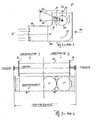
- zeigt eine mögliche Ausführungsvariante, in der der Fahrtwind F in einen Kanal 10 eintritt und nach oben abgelenkt wird.
- Figur 2
- ist eine Ansicht von vorne auf den Lufteintritt des Kanals 10, in zwei Varianten.
- Fig. 3, 3a
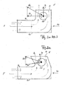
- ist eine Variante mit veränderter Umlenkung.
- Fig. 4, 4a
- ist eine weitere Variante mit veränderter Lage des rotierenden Zylinders.
- Figur 5
- ist eine Variante mit einem Leitblech vor dem Umlenkabschnitt.
- Figur 6
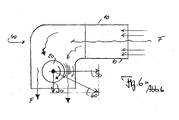
- ist eine Variante mit einer Umlenkung des Fahrtfluids nach unten.
- In Figur 1 ist eine erste Ausführungsvariante dargestellt. Der Fahrtwind F tritt in dieser Variante in einen Kanal 10 ein und wird nach oben abgelenkt, bevor er auf den waagerecht angeordneten rotierenden Zylinder 20 trifft. Es ergeben sich die erste Widerstandskraft 30 und die zweite Widerstandskraft 40, welche auf den Kanal 10 wirken. Der durch den rotierenden Zylinder erzeugte Quertrieb 50 ist jedoch um ein mehrfaches größer, und es ergibt sich die "resultierende Kraft" 60 als Vortrieb. Diese Kraft wird auf das (nicht dargestellte) Fahrzeug übertragen (in Figur 2 unterhalb des Kanals angedeutet).
- Wie in Figur 2 gezeigt, ist der rotierende Zylinder 20 in dieser Variante quer zur Fahrtrichtung angeordnet und in einer weiteren Variante, vorzugsweise mit Endscheiben 70 ausgestattet, um die Wirkung des Magnus-Effekts weiter zu verstärken. Diese Figur zeigt in Ansicht von vorn zwei Arten des Lufteintritts.
- Die Umlenkung des von vorn auftreffenden (und in den Kanal eintretenden) Luftstroms F kann in weiteren Varianten um einen von 90° abweichenden Winkel erfolgen, wie in Figuren 3, 3a gezeigt; hierdurch wird eine geänderte Richtung der resultierenden Kraft 60 erreicht.
- Wie Figuren 4, 4a zeigen, kann der durch den rotierenden Zylinder 20 erzeugte Quertrieb 50 in einer weiteren Variante dadurch erhöht werden, dass dieser Zylinder nicht in der Mitte, sondern asymmetrisch im Fluidkanal 10 angeordnet wird. Die Unterschiede in den Massen b, c zeigen das, bei gleichem Durchmesser d des rotierenden Zylinders 20.
- Durch diese asymmetrische Anordnung wird die Geschwindigkeit der Luft auf der in Fahrtrichtung liegenden Seite des Zylinders zusätzlich beschleunigt und der erzeugte Unterdruck zur Verursachung des Quertriebs 50 erhöht.
- Wie in Figur 5 dargestellt, kann der Fluidkanal vor seiner Umlenkung von einem Leitblech 80 abgedeckt werden, um den Luftwiderstand des Fahrtfluids zu reduzieren.
- Die Umlenkung des Fahrtwindes (als Beispiel des Fluids) kann sowohl nach oben als auch nach unten erfolgen. Die Richtung der resultierenden Kraft 60 wird hierdurch, wie in Figur 6 gezeigt, verlagert. In beiden Varianten wird jedoch ein Vortrieb erzeugt.
- Eine weitere, nicht dargestellte Variante hat einen oder mehrere, senkrecht angeordnete, rotierende Zylinder 20 (wie bei dem Flettner-Rotor). Eine Umlenkung des Luftstroms erfolgt in dem Fluidkanal 10 hierbei nach seitlich, um den gewünschten Vortrieb zu erzeugen.
- Der Windkanal 10 kann rechteckig, wie in Figuren 1,2 (Variante 1) dargestellt, ausgebildet sein. Der Windkanal 10 kann alternativ unterteilt sein; hierbei können diese (mehreren) Windkanäle jeweils rechteckig, elliptisch oder kreisförmig ausgebildet sein.
Claims (12)
- Verwendung einer Vortriebsanlage für ein mit einer ersten Vortriebsanlage bewegtes Fahrzeug, mit einem rotierenden, waagerecht angeordneten Zylinder (20) mit Endscheiben (70), als Zusatzvortrieb, wobei ein durch die erste Vortriebsanlage erzeugter Fluidstrom (F) in einen Kanal (10) eintritt und in dem Kanal in seiner Richtung umgelenkt wird und auf den rotierenden Zylinder (20) trifft, wodurch der ergänzende Vortrieb auf der Grundlage des Magnus-Effekts in einer gewünschten Richtung erzeugt wird.
- Verwendung einer Antriebsanlage auf der Grundlage des Magnus-Effekts mit einem rotierenden, senkrecht angeordneten Zylinder (20) mit Endscheiben, zusätzlich zu einer bestehenden Vortriebsanlage, wobei ein Fluidstrom (F) in einem Kanal (10) in seiner Richtung umgelenkt auf den rotierenden Zylinder (20) trifft und einen ergänzenden Vortrieb in einer gewünschten Richtung erzeugt.
- Verwendung nach Anspruch 1, bei welcher diese Umlenkung nach oben erfolgt.
- Verwendung nach Anspruch 1, bei welcher diese Umlenkung nach unten erfolgt
- Verwendung nach Anspruch 2, bei welcher diese Umlenkung seitlich erfolgt.
- Verwendung nach Anspruch 1 oder 2, bei welcher die Umlenkung um 90° erfolgt.
- Verwendung nach Anspruch 1 oder 2, bei welcher die Umlenkung um einen von 90° abweichenden Winkel erfolgt.
- Verwendung nach Anspruch 1 oder 2, bei welcher der rotierende Zylinder in der Mitte des Kanals (10) angebracht ist.
- Verwendung nach Anspruch 1 oder 2, bei welcher der rotierende Zylinder (20) asymmetrisch im Kanal angebracht ist.
- Verwendung nach Anspruch 1 oder 2, bei welcher der Kanal (10) durch ein Leitblech (80) zur Verringerung eines bei dem Vortrieb entstehenden Fluidwiderstandes vor dem Umlenkabschnitt abgedeckt ist.
- Verwendung nach Anspruch 1 oder 2 mit nur einem einzigen, rechteckigen Kanal (10).
- Verwendung nach Anspruch 1 oder 2 mit mehreren Kanälen (10), welche rechteckige, elliptische oder kreisförmige Querschnitte aufweisen.
Priority Applications (20)
| Application Number | Priority Date | Filing Date | Title |
|---|---|---|---|
| DE502004003459T DE502004003459D1 (de) | 2004-02-24 | 2004-02-24 | Zusatzantriebsanlage durch Umlenkung des Fluidstroms |
| SI200430358T SI1568602T1 (sl) | 2004-02-24 | 2004-02-24 | Dodatna pogonska priprava s preusmeritvijo toka fluida |
| ES04004172T ES2285289T3 (es) | 2004-02-24 | 2004-02-24 | Instalacion de propulsion auxiliar mediante la desviacion de la corriente de fluido. |
| AT04004172T ATE359208T1 (de) | 2004-02-24 | 2004-02-24 | Zusatzantriebsanlage durch umlenkung des fluidstroms |
| PT04004172T PT1568602E (pt) | 2004-02-24 | 2004-02-24 | Unidade de accionamento adicional atraves do desvio do fluxo de fluidos. |
| DK04004172T DK1568602T3 (da) | 2004-02-24 | 2004-02-24 | Supplerende fremdrivningsenhed omfattende omstyring af fluidströmmen |
| EP04004172A EP1568602B1 (de) | 2004-02-24 | 2004-02-24 | Zusatzantriebsanlage durch Umlenkung des Fluidstroms |
| PCT/EP2005/050775 WO2005080195A1 (de) | 2004-02-24 | 2005-02-23 | Zusatzantriebsanlage durch umlenkung des fluidstroms |
| AU2005214092A AU2005214092A1 (en) | 2004-02-24 | 2005-02-23 | Additional drive system by diverting a fluid flow |
| MXPA06009726A MXPA06009726A (es) | 2004-02-24 | 2005-02-23 | Sistema de propulsion adicional mediante el desvio del flujo de un fluido. |
| CA002557365A CA2557365A1 (en) | 2004-02-24 | 2005-02-23 | Additional drive system by diverting a fluid flow |
| EP05716776A EP1718524A1 (de) | 2004-02-24 | 2005-02-23 | Zusatzantriebsanlage durch umlenkung des fluidstroms |
| BRPI0507955-1A BRPI0507955A (pt) | 2004-02-24 | 2005-02-23 | sistema de acionamento adicional através de desvio da corrente de fluido |
| US10/598,157 US20070160472A1 (en) | 2004-02-24 | 2005-02-23 | Additional drive system by diverting a fluid flow |
| RU2006126240/11A RU2006126240A (ru) | 2004-02-24 | 2005-02-23 | Система дополнительного привода, основанная на отклонении потока рабочей среды |
| CNA2005800057827A CN101087714A (zh) | 2004-02-24 | 2005-02-23 | 通过转向流体流作用的附加驱动装置 |
| JP2006553597A JP2007522997A (ja) | 2004-02-24 | 2005-02-23 | 流体流の方向転換による補助駆動装置 |
| ZA200606822A ZA200606822B (en) | 2004-02-24 | 2006-08-16 | Additional drive system by deverting a fluid flow |
| NO20064331A NO20064331L (no) | 2004-02-24 | 2006-09-25 | Tilleggsdrivanlegg med omstyring av en fluidstrom |
| CY20071100775T CY1106651T1 (el) | 2004-02-24 | 2007-06-11 | Εγκατασταση προσθετης μεταδοσης κινησης μεσω αναστροφης της ροης του ρευστου |
Applications Claiming Priority (1)
| Application Number | Priority Date | Filing Date | Title |
|---|---|---|---|
| EP04004172A EP1568602B1 (de) | 2004-02-24 | 2004-02-24 | Zusatzantriebsanlage durch Umlenkung des Fluidstroms |
Publications (2)
| Publication Number | Publication Date |
|---|---|
| EP1568602A1 EP1568602A1 (de) | 2005-08-31 |
| EP1568602B1 true EP1568602B1 (de) | 2007-04-11 |
Family
ID=34745874
Family Applications (2)
| Application Number | Title | Priority Date | Filing Date |
|---|---|---|---|
| EP04004172A Expired - Lifetime EP1568602B1 (de) | 2004-02-24 | 2004-02-24 | Zusatzantriebsanlage durch Umlenkung des Fluidstroms |
| EP05716776A Withdrawn EP1718524A1 (de) | 2004-02-24 | 2005-02-23 | Zusatzantriebsanlage durch umlenkung des fluidstroms |
Family Applications After (1)
| Application Number | Title | Priority Date | Filing Date |
|---|---|---|---|
| EP05716776A Withdrawn EP1718524A1 (de) | 2004-02-24 | 2005-02-23 | Zusatzantriebsanlage durch umlenkung des fluidstroms |
Country Status (19)
| Country | Link |
|---|---|
| US (1) | US20070160472A1 (de) |
| EP (2) | EP1568602B1 (de) |
| JP (1) | JP2007522997A (de) |
| CN (1) | CN101087714A (de) |
| AT (1) | ATE359208T1 (de) |
| AU (1) | AU2005214092A1 (de) |
| BR (1) | BRPI0507955A (de) |
| CA (1) | CA2557365A1 (de) |
| CY (1) | CY1106651T1 (de) |
| DE (1) | DE502004003459D1 (de) |
| DK (1) | DK1568602T3 (de) |
| ES (1) | ES2285289T3 (de) |
| MX (1) | MXPA06009726A (de) |
| NO (1) | NO20064331L (de) |
| PT (1) | PT1568602E (de) |
| RU (1) | RU2006126240A (de) |
| SI (1) | SI1568602T1 (de) |
| WO (1) | WO2005080195A1 (de) |
| ZA (1) | ZA200606822B (de) |
Families Citing this family (11)
| Publication number | Priority date | Publication date | Assignee | Title |
|---|---|---|---|---|
| BRPI0813193A2 (pt) | 2007-08-02 | 2014-12-23 | Joel S Douglas | Coletor de energia, sistema coletor de energia para uso em um sistema de efluente, coletor de energia para colher energia do movimento das ondas em uma massa de fluido, coletor de energia rotativo, conjunto coletor de energia flutuante, sistema para coletar energia de um fluxo de corrente reversível de uma massa de água, sistema para coletar energia do fluxo de corrente e da ação das ondas de uma massa de água |
| KR101829690B1 (ko) * | 2010-02-15 | 2018-02-19 | 요른 파울 빙클러 | 접이식 매그너스-효과 로터를 포함하는 선박 |
| EP2374681A1 (de) * | 2010-04-12 | 2011-10-12 | Herbert Gernert | Vorrichtung für Fahrzeuge und Verfahren zum Betrieb eines Fahrzeugs |
| CN101898635B (zh) * | 2010-07-26 | 2013-03-27 | 哈尔滨工业大学 | 基于马格努斯效应的涵道单螺旋桨飞行器 |
| CN101930683B (zh) * | 2010-09-07 | 2011-10-05 | 河海大学 | 无风洞马格努斯效应演示实验装置 |
| DE102010040905A1 (de) * | 2010-09-16 | 2012-03-22 | Aloys Wobben | Schiff |
| PL218215B1 (pl) * | 2012-06-26 | 2014-10-31 | Jerzy Bolesław Wasilewski | Turbina wiatrowa |
| US10118696B1 (en) | 2016-03-31 | 2018-11-06 | Steven M. Hoffberg | Steerable rotating projectile |
| US11712637B1 (en) | 2018-03-23 | 2023-08-01 | Steven M. Hoffberg | Steerable disk or ball |
| US10859065B1 (en) * | 2019-12-12 | 2020-12-08 | Li Li | Supplemental propulsion system for vehicles |
| CN116293012A (zh) * | 2023-02-20 | 2023-06-23 | 上海风神环境设备工程有限公司 | 马格努斯风量调节阀 |
Family Cites Families (38)
| Publication number | Priority date | Publication date | Assignee | Title |
|---|---|---|---|---|
| GB371691A (en) * | 1930-07-07 | 1932-04-28 | Nicholas John Medvedeff | Improvements in or relating to flying machines |
| GB494093A (en) * | 1937-04-16 | 1938-10-17 | Ivan Alexander Gavrilof | Method and apparatus for controlling ships and like vessels |
| US2985406A (en) * | 1959-04-29 | 1961-05-23 | Bump Harold Wilson | Aircraft sustained by cylindrical rotors |
| US3065928A (en) * | 1960-07-16 | 1962-11-27 | Dornier Werke Gmbh | Multiple drive for aircraft having wings provided with transverse flow blowers |
| US3017848A (en) * | 1960-11-14 | 1962-01-23 | Charles R Bishop | Boat propulsion unit |
| US3276415A (en) * | 1961-12-12 | 1966-10-04 | Firth Cleveland Ltd | Device consisting of a drive and a rotating wheel producing thrust for the propulsion of boats |
| US3140065A (en) * | 1962-06-27 | 1964-07-07 | Alvarez-Calderon Alberto | High lift and control system for aircraft |
| IT942612B (it) * | 1970-10-14 | 1973-04-02 | Buderus Eisenwerk | Ventilatore |
| CA1013321A (en) * | 1972-12-28 | 1977-07-05 | Takeshi Aizawa | Blower |
| FR2298706A1 (fr) * | 1975-01-22 | 1976-08-20 | Sicard Charles | Dispositif tournant actionne par un fluide en mouvement |
| CA1073276A (en) * | 1976-09-08 | 1980-03-11 | John Guthrie | Wind powered apparatus |
| US4113299A (en) * | 1976-10-04 | 1978-09-12 | Johnson David W | Rotating magnus tubes |
| US4134469A (en) * | 1976-10-08 | 1979-01-16 | Turbopanel Motors, Inc. | Linear turbine |
| US4132282A (en) * | 1977-01-17 | 1979-01-02 | Sparks Keith L | Automotive electric generator |
| US4168759A (en) * | 1977-10-06 | 1979-09-25 | Hull R Dell | Automobile with wind driven generator |
| US4179007A (en) * | 1978-06-01 | 1979-12-18 | Howe Robert R | Wind operated power generating apparatus |
| GB2072112B (en) * | 1980-03-20 | 1983-08-24 | Austin K A | Rotors utilising the magnus effect |
| US4502724A (en) * | 1980-10-16 | 1985-03-05 | Grenadier R Miles | Vehicle payload lightener |
| US4582013A (en) * | 1980-12-23 | 1986-04-15 | The Holland Corporation | Self-adjusting wind power machine |
| US4398895A (en) * | 1981-05-14 | 1983-08-16 | Asker Gunnar C F | Wind propulsion devices |
| DE3123287C2 (de) * | 1981-06-12 | 1986-06-05 | Blohm + Voss Ag, 2000 Hamburg | Windantrieb für Schiffe |
| US4630997A (en) * | 1981-11-24 | 1986-12-23 | Fondation Cousteau | Apparatus for producing a force when in a moving fluid |
| US4576581A (en) * | 1981-11-30 | 1986-03-18 | Borg John L | Reversible Magnus propeller |
| US4602584A (en) * | 1984-06-12 | 1986-07-29 | Henry North | Propulsion device for a ship |
| GB2179014A (en) * | 1985-07-19 | 1987-02-25 | Thomas Macduff | Improvements in propulsion systems |
| GB9111851D0 (en) * | 1991-06-03 | 1991-07-24 | Macduff Thomas | A marine propulsion system |
| US5287004A (en) * | 1992-09-04 | 1994-02-15 | Finley Michael D | Automobile air and ground effects power package |
| US5296746A (en) * | 1992-12-17 | 1994-03-22 | Burkhardt Harry E | Extended range charging system for electrical vehicle |
| US5280827A (en) * | 1992-12-22 | 1994-01-25 | Cletus L. Taylor | Venturi effect charging system for automobile batteries |
| US5386146A (en) * | 1993-04-22 | 1995-01-31 | Hickey; John J. | In-line auger driven charging system |
| US5875627A (en) * | 1995-06-07 | 1999-03-02 | Jeswine; William W. | Fluid propulsion system for accelerating and directionally controlling a fluid |
| US6138781A (en) * | 1997-08-13 | 2000-10-31 | Hakala; James R. | System for generating electricity in a vehicle |
| US7147069B2 (en) * | 2002-05-08 | 2006-12-12 | Maberry Robert L | Wind turbine driven generator system for a motor vehicle |
| US6857492B1 (en) * | 2003-01-09 | 2005-02-22 | Airflow driven electrical generator for a moving vehicle | |
| US6897575B1 (en) * | 2003-04-16 | 2005-05-24 | Xiaoying Yu | Portable wind power apparatus for electric vehicles |
| US6910873B2 (en) * | 2003-08-20 | 2005-06-28 | Arthur Kaliski | Self regulating rotor |
| US7398841B2 (en) * | 2004-05-17 | 2008-07-15 | Jay Stephen Kaufman | Vehicle power assist by brake, shock, solar, and wind energy recovery |
| US7135786B1 (en) * | 2006-02-11 | 2006-11-14 | Edward Deets | Wind driven generator for powered vehicles |
-
2004
- 2004-02-24 DE DE502004003459T patent/DE502004003459D1/de not_active Expired - Fee Related
- 2004-02-24 DK DK04004172T patent/DK1568602T3/da active
- 2004-02-24 ES ES04004172T patent/ES2285289T3/es not_active Expired - Lifetime
- 2004-02-24 SI SI200430358T patent/SI1568602T1/sl unknown
- 2004-02-24 PT PT04004172T patent/PT1568602E/pt unknown
- 2004-02-24 AT AT04004172T patent/ATE359208T1/de not_active IP Right Cessation
- 2004-02-24 EP EP04004172A patent/EP1568602B1/de not_active Expired - Lifetime
-
2005
- 2005-02-23 WO PCT/EP2005/050775 patent/WO2005080195A1/de not_active Ceased
- 2005-02-23 CN CNA2005800057827A patent/CN101087714A/zh active Pending
- 2005-02-23 AU AU2005214092A patent/AU2005214092A1/en not_active Abandoned
- 2005-02-23 BR BRPI0507955-1A patent/BRPI0507955A/pt not_active IP Right Cessation
- 2005-02-23 CA CA002557365A patent/CA2557365A1/en not_active Abandoned
- 2005-02-23 RU RU2006126240/11A patent/RU2006126240A/ru not_active Application Discontinuation
- 2005-02-23 MX MXPA06009726A patent/MXPA06009726A/es not_active Application Discontinuation
- 2005-02-23 JP JP2006553597A patent/JP2007522997A/ja not_active Withdrawn
- 2005-02-23 EP EP05716776A patent/EP1718524A1/de not_active Withdrawn
- 2005-02-23 US US10/598,157 patent/US20070160472A1/en not_active Abandoned
-
2006
- 2006-08-16 ZA ZA200606822A patent/ZA200606822B/xx unknown
- 2006-09-25 NO NO20064331A patent/NO20064331L/no not_active Application Discontinuation
-
2007
- 2007-06-11 CY CY20071100775T patent/CY1106651T1/el unknown
Also Published As
| Publication number | Publication date |
|---|---|
| RU2006126240A (ru) | 2008-03-27 |
| MXPA06009726A (es) | 2007-08-15 |
| ES2285289T3 (es) | 2007-11-16 |
| NO20064331L (no) | 2006-09-25 |
| SI1568602T1 (sl) | 2007-10-31 |
| EP1568602A1 (de) | 2005-08-31 |
| DE502004003459D1 (de) | 2007-05-24 |
| WO2005080195A1 (de) | 2005-09-01 |
| ATE359208T1 (de) | 2007-05-15 |
| ZA200606822B (en) | 2007-12-27 |
| US20070160472A1 (en) | 2007-07-12 |
| EP1718524A1 (de) | 2006-11-08 |
| AU2005214092A1 (en) | 2005-09-01 |
| BRPI0507955A (pt) | 2007-07-17 |
| CN101087714A (zh) | 2007-12-12 |
| CA2557365A1 (en) | 2005-09-01 |
| PT1568602E (pt) | 2007-07-17 |
| JP2007522997A (ja) | 2007-08-16 |
| DK1568602T3 (da) | 2007-08-20 |
| CY1106651T1 (el) | 2012-01-25 |
Similar Documents
| Publication | Publication Date | Title |
|---|---|---|
| EP1568602B1 (de) | Zusatzantriebsanlage durch Umlenkung des Fluidstroms | |
| EP1986912A2 (de) | Aerodynamische klappe eines flugzeugs mit einer den klappenwirbel beeinflussenden vorrichtung | |
| DE3029099A1 (de) | Symmetrische schiffsschraube | |
| DE2530592C2 (de) | Vorrichtung zur weiteren Aufbereitung von Brennstoff-Luft-Gemischen für eine Brennkraftmaschine | |
| WO2016096813A1 (de) | Luftleitung für einen ansaugtrakt einer verbrennungskraftmaschine, insbesondere eines kraftwagens | |
| DE112024000030T5 (de) | Rotorblatt, mittel zur geräuschreduzierung für ein rotorblatt und verfahren zur geräuschreduzierung für ein rotorblatt | |
| DE3403636C2 (de) | Vorrichtung zur Verstärkung der Bodenhaftung für ein Kraftfahrzeug | |
| DE69120541T2 (de) | Ummanteltes schraubensystem für ein segelboot | |
| DE2637985C3 (de) | Einrichtung zur Erzeugung einer Drallbewegung der Zylinderladung für ventilgesteuerte Kolbenbrennkraftmaschinen | |
| DE102024003746B3 (de) | Luftleiteinrichtung für einen Personenkraftwagen sowie Personenkraftwagen | |
| DE2212952A1 (de) | Schienenfahrzeug oder schienenzug, vorzugsweise fuer schnellbahnen | |
| DE2460283A1 (de) | Der kavitation entgegenwirkende einrichtung fuer boots- oder schiffsschrauben | |
| DE10314057B3 (de) | Schnorchelvorrichtung für ein U-Boot | |
| DE4340028C2 (de) | Abdriftverminderndes System für windgetriebene Schiffe | |
| DE102008057601B4 (de) | Vorrichtung zur Verringerung des Wasserwiderstands von Schiffen | |
| DE8317717U1 (de) | Vorrichtung zum verstellen der steigung der fluegelblaetter eines propellers | |
| DE1926148A1 (de) | Flachbodenboot mit erhoehter Fahrleistung ohne- zum normalen Antrieb-zusaetzlichen Energieaufwand | |
| DE102016112876A1 (de) | Durchströmwindkraftanlage | |
| DE102012012796A1 (de) | Brennkraftmaschine für ein Kraftfahrzeug | |
| DE102006026627B4 (de) | Luftleitvorrichtung für Motorräder | |
| DE102020002086A1 (de) | Prallschraube | |
| WO2022180008A1 (de) | Energiesparanordnung für doppelschraubenschiffe | |
| EP4620792A1 (de) | Neigefahrzeug | |
| DE102004033977A1 (de) | Kühlventilator mit Luftführung | |
| DE102022003758A1 (de) | Vorrichtung zum Verbessern der aerodynamischen Leistung von Fahrzeugen |
Legal Events
| Date | Code | Title | Description |
|---|---|---|---|
| PUAI | Public reference made under article 153(3) epc to a published international application that has entered the european phase |
Free format text: ORIGINAL CODE: 0009012 |
|
| 17P | Request for examination filed |
Effective date: 20050128 |
|
| AK | Designated contracting states |
Kind code of ref document: A1 Designated state(s): AT BE BG CH CY CZ DE DK EE ES FI FR GB GR HU IE IT LI LU MC NL PT RO SE SI SK TR |
|
| AX | Request for extension of the european patent |
Extension state: AL LT LV MK |
|
| AKX | Designation fees paid |
Designated state(s): AT BE BG CH CY CZ DE DK EE ES FI FR GB GR HU IE IT LI LU MC NL PT RO SE SI SK TR |
|
| GRAP | Despatch of communication of intention to grant a patent |
Free format text: ORIGINAL CODE: EPIDOSNIGR1 |
|
| RAP1 | Party data changed (applicant data changed or rights of an application transferred) |
Owner name: WOLFGANG JOBMANN GMBH |
|
| RIN1 | Information on inventor provided before grant (corrected) |
Inventor name: WOLFGANG JOBMANN GMBH |
|
| GRAS | Grant fee paid |
Free format text: ORIGINAL CODE: EPIDOSNIGR3 |
|
| GRAA | (expected) grant |
Free format text: ORIGINAL CODE: 0009210 |
|
| RIN1 | Information on inventor provided before grant (corrected) |
Inventor name: DIE ERFINDER HABEN AUF IHRE NENNUNG VERZICHTET. |
|
| RIN1 | Information on inventor provided before grant (corrected) |
Inventor name: STAMME, PETER Inventor name: JOBMANN, WOLFGANG |
|
| AK | Designated contracting states |
Kind code of ref document: B1 Designated state(s): AT BE BG CH CY CZ DE DK EE ES FI FR GB GR HU IE IT LI LU MC NL PT RO SE SI SK TR |
|
| REG | Reference to a national code |
Ref country code: GB Ref legal event code: FG4D Free format text: NOT ENGLISH |
|
| REG | Reference to a national code |
Ref country code: CH Ref legal event code: EP |
|
| REG | Reference to a national code |
Ref country code: IE Ref legal event code: FG4D Free format text: LANGUAGE OF EP DOCUMENT: GERMAN |
|
| REF | Corresponds to: |
Ref document number: 502004003459 Country of ref document: DE Date of ref document: 20070524 Kind code of ref document: P |
|
| REG | Reference to a national code |
Ref country code: RO Ref legal event code: EPE |
|
| REG | Reference to a national code |
Ref country code: CH Ref legal event code: NV Representative=s name: KELLER & PARTNER PATENTANWAELTE AG |
|
| GBT | Gb: translation of ep patent filed (gb section 77(6)(a)/1977) |
Effective date: 20070607 |
|
| REG | Reference to a national code |
Ref country code: PT Ref legal event code: SC4A Free format text: AVAILABILITY OF NATIONAL TRANSLATION Effective date: 20070705 |
|
| REG | Reference to a national code |
Ref country code: GR Ref legal event code: EP Ref document number: 20070401830 Country of ref document: GR |
|
| REG | Reference to a national code |
Ref country code: SE Ref legal event code: TRGR |
|
| REG | Reference to a national code |
Ref country code: DK Ref legal event code: T3 |
|
| ET | Fr: translation filed | ||
| REG | Reference to a national code |
Ref country code: ES Ref legal event code: FG2A Ref document number: 2285289 Country of ref document: ES Kind code of ref document: T3 |
|
| REG | Reference to a national code |
Ref country code: HU Ref legal event code: AG4A Ref document number: E002026 Country of ref document: HU |
|
| PLBE | No opposition filed within time limit |
Free format text: ORIGINAL CODE: 0009261 |
|
| STAA | Information on the status of an ep patent application or granted ep patent |
Free format text: STATUS: NO OPPOSITION FILED WITHIN TIME LIMIT |
|
| 26N | No opposition filed |
Effective date: 20080114 |
|
| PGFP | Annual fee paid to national office [announced via postgrant information from national office to epo] |
Ref country code: ES Payment date: 20080201 Year of fee payment: 5 Ref country code: DK Payment date: 20080206 Year of fee payment: 5 Ref country code: CH Payment date: 20080215 Year of fee payment: 5 |
|
| PGFP | Annual fee paid to national office [announced via postgrant information from national office to epo] |
Ref country code: SI Payment date: 20080222 Year of fee payment: 5 Ref country code: SE Payment date: 20080213 Year of fee payment: 5 Ref country code: PT Payment date: 20080201 Year of fee payment: 5 Ref country code: NL Payment date: 20080220 Year of fee payment: 5 Ref country code: MC Payment date: 20080131 Year of fee payment: 5 Ref country code: LU Payment date: 20080229 Year of fee payment: 5 Ref country code: IE Payment date: 20080131 Year of fee payment: 5 Ref country code: HU Payment date: 20080219 Year of fee payment: 5 Ref country code: GB Payment date: 20080206 Year of fee payment: 5 Ref country code: FI Payment date: 20080201 Year of fee payment: 5 Ref country code: EE Payment date: 20080205 Year of fee payment: 5 Ref country code: BG Payment date: 20080229 Year of fee payment: 5 |
|
| PGFP | Annual fee paid to national office [announced via postgrant information from national office to epo] |
Ref country code: CY Payment date: 20080218 Year of fee payment: 5 Ref country code: RO Payment date: 20080124 Year of fee payment: 5 Ref country code: AT Payment date: 20080220 Year of fee payment: 5 |
|
| PGFP | Annual fee paid to national office [announced via postgrant information from national office to epo] |
Ref country code: FR Payment date: 20080228 Year of fee payment: 5 Ref country code: DE Payment date: 20080429 Year of fee payment: 5 Ref country code: CZ Payment date: 20080208 Year of fee payment: 5 |
|
| PGFP | Annual fee paid to national office [announced via postgrant information from national office to epo] |
Ref country code: BE Payment date: 20080206 Year of fee payment: 5 |
|
| PGFP | Annual fee paid to national office [announced via postgrant information from national office to epo] |
Ref country code: TR Payment date: 20080201 Year of fee payment: 5 |
|
| PGFP | Annual fee paid to national office [announced via postgrant information from national office to epo] |
Ref country code: SK Payment date: 20080229 Year of fee payment: 5 |
|
| PGFP | Annual fee paid to national office [announced via postgrant information from national office to epo] |
Ref country code: GR Payment date: 20080214 Year of fee payment: 5 |
|
| BERE | Be: lapsed |
Owner name: WOLFGANG JOBMANN G.M.B.H. Effective date: 20090228 |
|
| PG25 | Lapsed in a contracting state [announced via postgrant information from national office to epo] |
Ref country code: IT Free format text: LAPSE BECAUSE OF NON-PAYMENT OF DUE FEES Effective date: 20080224 |
|
| PGFP | Annual fee paid to national office [announced via postgrant information from national office to epo] |
Ref country code: IT Payment date: 20080228 Year of fee payment: 5 |
|
| REG | Reference to a national code |
Ref country code: PT Ref legal event code: MM4A Free format text: LAPSE DUE TO NON-PAYMENT OF FEES Effective date: 20090824 |
|
| PG25 | Lapsed in a contracting state [announced via postgrant information from national office to epo] |
Ref country code: MC Free format text: LAPSE BECAUSE OF NON-PAYMENT OF DUE FEES Effective date: 20090228 |
|
| REG | Reference to a national code |
Ref country code: CH Ref legal event code: PL |
|
| EUG | Se: european patent has lapsed | ||
| REG | Reference to a national code |
Ref country code: EE Ref legal event code: MM4A Ref document number: E001208 Country of ref document: EE Effective date: 20090228 |
|
| REG | Reference to a national code |
Ref country code: DK Ref legal event code: EBP |
|
| GBPC | Gb: european patent ceased through non-payment of renewal fee |
Effective date: 20090224 |
|
| PG25 | Lapsed in a contracting state [announced via postgrant information from national office to epo] |
Ref country code: PT Free format text: LAPSE BECAUSE OF NON-PAYMENT OF DUE FEES Effective date: 20090824 Ref country code: LI Free format text: LAPSE BECAUSE OF NON-PAYMENT OF DUE FEES Effective date: 20090228 Ref country code: FI Free format text: LAPSE BECAUSE OF NON-PAYMENT OF DUE FEES Effective date: 20090224 Ref country code: EE Free format text: LAPSE BECAUSE OF NON-PAYMENT OF DUE FEES Effective date: 20090228 Ref country code: CZ Free format text: LAPSE BECAUSE OF NON-PAYMENT OF DUE FEES Effective date: 20090224 Ref country code: CH Free format text: LAPSE BECAUSE OF NON-PAYMENT OF DUE FEES Effective date: 20090228 Ref country code: AT Free format text: LAPSE BECAUSE OF NON-PAYMENT OF DUE FEES Effective date: 20090224 |
|
| NLV4 | Nl: lapsed or anulled due to non-payment of the annual fee |
Effective date: 20090901 |
|
| REG | Reference to a national code |
Ref country code: FR Ref legal event code: ST Effective date: 20091030 |
|
| PG25 | Lapsed in a contracting state [announced via postgrant information from national office to epo] |
Ref country code: SK Free format text: LAPSE BECAUSE OF NON-PAYMENT OF DUE FEES Effective date: 20090224 Ref country code: SI Free format text: LAPSE BECAUSE OF NON-PAYMENT OF DUE FEES Effective date: 20090225 Ref country code: NL Free format text: LAPSE BECAUSE OF NON-PAYMENT OF DUE FEES Effective date: 20090901 Ref country code: HU Free format text: LAPSE BECAUSE OF NON-PAYMENT OF DUE FEES Effective date: 20090225 |
|
| PG25 | Lapsed in a contracting state [announced via postgrant information from national office to epo] |
Ref country code: CY Free format text: LAPSE BECAUSE OF NON-PAYMENT OF DUE FEES Effective date: 20090224 |
|
| REG | Reference to a national code |
Ref country code: SI Ref legal event code: KO00 Effective date: 20091008 |
|
| PG25 | Lapsed in a contracting state [announced via postgrant information from national office to epo] |
Ref country code: RO Free format text: LAPSE BECAUSE OF NON-PAYMENT OF DUE FEES Effective date: 20090224 Ref country code: IE Free format text: LAPSE BECAUSE OF NON-PAYMENT OF DUE FEES Effective date: 20090224 Ref country code: DE Free format text: LAPSE BECAUSE OF NON-PAYMENT OF DUE FEES Effective date: 20090901 |
|
| PG25 | Lapsed in a contracting state [announced via postgrant information from national office to epo] |
Ref country code: GR Free format text: LAPSE BECAUSE OF NON-PAYMENT OF DUE FEES Effective date: 20090902 Ref country code: BE Free format text: LAPSE BECAUSE OF NON-PAYMENT OF DUE FEES Effective date: 20090228 |
|
| REG | Reference to a national code |
Ref country code: ES Ref legal event code: FD2A Effective date: 20090225 |
|
| PG25 | Lapsed in a contracting state [announced via postgrant information from national office to epo] |
Ref country code: GB Free format text: LAPSE BECAUSE OF NON-PAYMENT OF DUE FEES Effective date: 20090224 Ref country code: FR Free format text: LAPSE BECAUSE OF NON-PAYMENT OF DUE FEES Effective date: 20090302 |
|
| PG25 | Lapsed in a contracting state [announced via postgrant information from national office to epo] |
Ref country code: ES Free format text: LAPSE BECAUSE OF NON-PAYMENT OF DUE FEES Effective date: 20090225 Ref country code: DK Free format text: LAPSE BECAUSE OF NON-PAYMENT OF DUE FEES Effective date: 20090831 |
|
| PG25 | Lapsed in a contracting state [announced via postgrant information from national office to epo] |
Ref country code: BG Free format text: LAPSE BECAUSE OF FAILURE TO SUBMIT A TRANSLATION OF THE DESCRIPTION OR TO PAY THE FEE WITHIN THE PRESCRIBED TIME-LIMIT Effective date: 20090228 |
|
| PG25 | Lapsed in a contracting state [announced via postgrant information from national office to epo] |
Ref country code: LU Free format text: LAPSE BECAUSE OF NON-PAYMENT OF DUE FEES Effective date: 20090224 |
|
| PG25 | Lapsed in a contracting state [announced via postgrant information from national office to epo] |
Ref country code: SE Free format text: LAPSE BECAUSE OF NON-PAYMENT OF DUE FEES Effective date: 20090225 |
|
| PG25 | Lapsed in a contracting state [announced via postgrant information from national office to epo] |
Ref country code: TR Free format text: LAPSE BECAUSE OF NON-PAYMENT OF DUE FEES Effective date: 20090224 |