EP1568588B1 - Motorisierte vordere Gangschaltung Halterung - Google Patents
Motorisierte vordere Gangschaltung Halterung Download PDFInfo
- Publication number
- EP1568588B1 EP1568588B1 EP04029086A EP04029086A EP1568588B1 EP 1568588 B1 EP1568588 B1 EP 1568588B1 EP 04029086 A EP04029086 A EP 04029086A EP 04029086 A EP04029086 A EP 04029086A EP 1568588 B1 EP1568588 B1 EP 1568588B1
- Authority
- EP
- European Patent Office
- Prior art keywords
- front derailleur
- mounting portion
- motorized
- mounting member
- link
- Prior art date
- Legal status (The legal status is an assumption and is not a legal conclusion. Google has not performed a legal analysis and makes no representation as to the accuracy of the status listed.)
- Revoked
Links
Images


Classifications
-
- B—PERFORMING OPERATIONS; TRANSPORTING
- B62—LAND VEHICLES FOR TRAVELLING OTHERWISE THAN ON RAILS
- B62M—RIDER PROPULSION OF WHEELED VEHICLES OR SLEDGES; POWERED PROPULSION OF SLEDGES OR SINGLE-TRACK CYCLES; TRANSMISSIONS SPECIALLY ADAPTED FOR SUCH VEHICLES
- B62M9/00—Transmissions characterised by use of an endless chain, belt, or the like
- B62M9/04—Transmissions characterised by use of an endless chain, belt, or the like of changeable ratio
- B62M9/06—Transmissions characterised by use of an endless chain, belt, or the like of changeable ratio using a single chain, belt, or the like
- B62M9/10—Transmissions characterised by use of an endless chain, belt, or the like of changeable ratio using a single chain, belt, or the like involving different-sized wheels, e.g. rear sprocket chain wheels selectively engaged by the chain, belt, or the like
- B62M9/12—Transmissions characterised by use of an endless chain, belt, or the like of changeable ratio using a single chain, belt, or the like involving different-sized wheels, e.g. rear sprocket chain wheels selectively engaged by the chain, belt, or the like the chain, belt, or the like being laterally shiftable, e.g. using a rear derailleur
- B62M9/131—Front derailleurs
- B62M9/132—Front derailleurs electrically or fluid actuated; Controls thereof
Definitions
- This invention generally relates to a motorized front derailleur mounting member. More specifically, the present invention relates to a motorized front derailleur mounting member that supports a bicycle derailleur and a motor to a frame of a bicycle.
- Bicycling is becoming an increasingly more popular form of recreation as well as a means of transportation. Moreover, bicycling has become a very popular competitive sport for both amateurs and professionals. Whether the bicycle is used for recreation, transportation or competition, the bicycle industry is constantly improving the various components of the bicycle.
- bicycles have been equipped with electrical components to make riding easier and more enjoyable for the rider.
- Some bicycles are equipped with automatic shifting units that are automatically adjusted according to the riding conditions by a cycle computer or control unit.
- the front and rear deraille have recently been automated.
- a front derailleur is typically secured to the seat tube of the bicycle frame or the bottom bracket.
- a front derailleur includes a fixed or base member non-movably secured to a bicycle frame, and a movable member supported to be movable relative to the fixed member.
- the fixed member is a tubular clamping member that is secured to the seat tube.
- the movable member typically has a chain guide with a pair of cage plates for contacting and moving a chain between the front sprockets.
- the movable member is usually biased in a given direction relative to the fixed member by a spring.
- the movable member is usually moved relative to the fixed member by pulling and/or releasing a shift control cable that is coupled to the front derailleur.
- the movable member and the fixed member usually are interconnected through pivotal links.
- a control cable is connected to one of the pivotal links to apply a torque thereto, thereby causing the links to move the movable section.
- the control cable is fixed to the link in such a position that an operating force applied to the control cable. This force on the cable is converted into a link swinging torque.
- a motorized front derailleur a motor is used to pull and release a control cable or the motor is connected by a drive train to the front derailleur.
- One object of the present invention is to provide a motorized front derailleur mounting member for a motorized bicycle front derailleur assembly that supports a bicycle derailleur and a motor to a frame of a bicycle.
- Another object of the present invention is to provide a motorized front derailleur mounting member for a motorized bicycle front derailleur assembly that is configured and arranged to be easily adjusted.
- Another object of the present invention is to provide a motorized front derailleur mounting member for a motorized bicycle front derailleur assembly that is relatively simple and inexpensive to manufacture and assemble.
- a motorized front derailleur mounting member comprising a bicycle frame mounting portion, a front derailleur mounting portion and a motor unit mounting portion.
- Said bicycle frame mounting portion is configured in the range to be coupled toa seat tube of a bicycle frame by a bracket.
- Said front derailleur mounting portion is configured and arranged to be coupled to a linkage of a front derailleur, the front derailleur mounting portion including at least a first pivot point with a first pivot axis and the motor unit mounting portion is configured and arranged to be coupled to a motor unit.
- the bicycle frame mounting portion the front derailleur mounting portion and the motor unit mounting portion are integrally formed as a one-piece unitary member including a projection that projects outwardly from a first side of the motorized front derailleur mounting member to a free end that forms a curved front surface.
- the said curved front surface of the frame mounting portion has a threaded hole and is configured and arranged to contact a corresponding curved portion of the bracket such that the motorized front derailleur mounting member cannot rotate relative to the bracket.
- a motorized front derailleur assembly comprising a motorized front derailleur mounting member, a chain guide, a first link and a second link.
- the motorized front derailleur mounting member includes a bicycle frame mounting portion, a front derailleur mounting portion, a motor unit mounting portion.
- the bicycle frame mounting portion includes a front surface with a threaded hole configured and arranged to be coupled to a bicycle frame.
- the front derailleur mounting portion is configured and arranged to form a fixing body having first and second fixed pivot points.
- the motor unit mounting portion is configured and arranged to be coupled to a motor unit.
- the chain guide has first and second shifted pivot points.
- the first link has a first end pivotally coupled to the first fixed pivot point of the fixing body and a second end pivotally coupled to the first shifted point of the chain guide.
- the second link has a first end pivotally coupled to the second fixed pivot point of the fixing body and a second end pivotally coupled to the second shifted point of the chain guide.
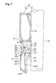
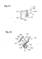
- a bicycle 10 is illustrated that is equipped with a motorized front derailleur assembly 12 in accordance with a first embodiment of the present invention.
- the bicycle 10 further includes a bicycle frame 14 having a seat tube 16 with the motorized front derailleur assembly 12 mounted to the seat tube 16 by a bracket 18 and fasteners or bolts 19 as seen in Figures 1-5 .
- the front derailleur 12 is operated in a conventional manner by an electronic shifting unit 20 coupled to an electrical control device via an electric shift cable to move a chain 21 between at least two front sprockets or chain wheels 22 and 23 of the bicycle drive train 24.
- Each control device is preferably provided with a pair of shift buttons that are operatively coupled to the electronic shifting unit 20 , preferably in accordance with U.S. Patent No. 6,073,730 (assigned to Shimano, Inc.) and U.S. Patent No. 6,212,078 (assigned to Shimano, Inc.).
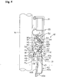
- the motorized front derailleur assembly 12 basically includes a motorized front derailleur unit 31, a motorized front derailleur mounting member 32, a front derailleur motor unit 33 and a motor linkage 34.
- the motorized front derailleur unit 31, the front derailleur motor unit 33 and the motor linkage 34 are all mounted on the motorized front derailleur mounting member 32 that is configured and arranged to fixedly couple the motorized derailleur assembly 12 to the seat tube 16 of the bicycle frame 14.
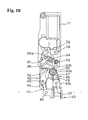
- the motorized front derailleur assembly 12 is constructed to move between at least a below shift position as illustrated in Figures 1-6 and a top shift position as illustrated in Figures 7-10 .
- the motor linkage 34 is designed with a derailleur protection arrangement such that the derailleur motor unit 33 can operated even though the motorized front derailleur unit 32 becomes jammed.
- the basic operation of shifting the chain 21 is relatively conventional, and thus, will not be illustrated shown in detail herein.
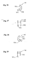
- the front derailleur unit 31 basically includes a chain guide 40, a derailleur linkage 41 and a fixing body 42 that is part of the mounting member 32, as explained below.
- the derailleur linkage 41 together with the chain guide 40 and the fixing body 42 preferably form a four-bar linkage that controls the lateral movement of the chain guide 40.
- the derailleur linkage 41 is configured and arranged to operatively couple between the fixing body 42 and the chain guide 40 for lateral movement of the chain guide 40 between at least a top shift position and a low shift position, i.e., at least first and second shift positions.
- the chain guide 40 is movably coupled to the fixing body 42 by a derailleur linkage 41 that is operatively coupled to the motor linkage 34 to move the chain guide 40 between a first shift position and a second shift position in response to operation of front derailleur motor unit 33.
- This lateral movement of the chain guide 40 causes the chain 21 to be shift between the sprockets 22 and 23 of the bicycle drive train 24.
- the chain guide 40 is preferably constructed of a hard rigid material.
- the chain guide 40 is preferably constructed of a metal material such as a rigid sheet metal that is bent to the desired shape.
- the chain guide 40 has first and second shifted pivot points P 1 and P 2 , respectively, for pivotally securing the derailleur linkage 41 to the chain guide 40.
- pivot pins 43 and 44 pivotally couple the chain guide 40 to the derailleur linkage 41.
- the chain guide 40 has a chain receiving slot that is formed by a pair of vertical shift plates 40a and 40b. The vertical shift plates 40a and 40b are adapted to engage the chain 21 and thus move the chain 21 in a direction substantially transverse to the bicycle 10.
- the shift plates 40a and 40b are connected together by a pair of plates 40c and 40d.
- the upper plate 40c is integrally formed between the shift plates 40a and 40b.
- the lower plate 40d has one end that is integrally formed with the outer shift plate 40b and the other end that is attached to the inner shift plate 40a via a fastener, such as a screw or rivet.
- the derailleur linkage 41 basically includes a first or outer link 45 and a second or inner link 46 with first ends pivotally coupled to the fixing body 42 and with second ends pivotally coupled to the chain guide 40.
- the first link 45 has a first end 45a pivotally coupled to a first fixed pivot point P 3 of the fixing body 42 by a pivot pin 47 and a second end 45b pivotally coupled to the first shifted pivot point P 1 of the chain guide 40 by the pivot pin 43.
- the second link 46 has a first end 46a pivotally coupled to a second fixed pivot point P 4 of the fixing body 42 by a pivot pin 48 and a second end 46b pivotally coupled to the second shifted pivot point P 2 of the chain guide 40 by the pivot pin 44.
- the derailleur linkage 41 is preferably a four-bar linkage that is formed by the first or outer link 45, the second or inner link 46, the portion of the chain guide 40 extending between the first and second shifted pivot points P 1 and P 2 , and the portion of the fixing body 42 extending between the first and second pivot fixed points P 3 and P 4 .
- pivot axes of the pivot points P 1 , P 2 , P 3 and P4 are all substantially parallel to each other.
- the chain guide 40 When the derailleur linkage 41 holds the chain guide 40 in its extended most position, the chain guide 40 is located over the outermost sprocket 22, i.e., the furthest sprocket from the seat tube 16. When the derailleur linkage 41 holds the chain guide 40 in its retracted most position, the chain guide 40 is located over the innermost sprocket 23, i.e., the closet sprocket to the seat tube 16.
- the first or outer link 45 includes two threaded holes 45c and 45d that receive a top position adjustment screw 49 and a low position adjustment screw 50.
- the two threaded holes 45c and 45d of the first or outer link 45 and the adjustment screws 49 and 50 form a mechanical adjustment device that finely adjusts the top and low positions of the chain guide 40.
- the mechanical adjustment device is configured and arranged to change the first and second shift positions of the chain guide 40 relative to the fixing body 42.
- the first or low adjustment screw 50 is configured and arranged to change the first or low shift position of the chain guide 40 relative to the fixing body 42
- the second or top adjustment screw 49 is configured and arranged to change the second or top shift position of the chain guide 40 relative to the fixing body 42.
- adjustment screws 49 and 50 are mounted on the first or outer link 45, it will be apparent from this disclosure that the adjustment screws 49 and 50 can be mounted on any one of the fixing body 42, the chain guide 40 and the links 45 and 46 with a free end of the adjustment screw contacting one of the fixing body 42, the chain guide 40 and the links 45 and 46 or the motor linkage 34 in which the adjustment screw is not threadedly coupled thereto. Also it will be apparent from this disclosure that an adjustment screw can be threadedly coupled to one of the motor linkage 34 and the derailleur linkage 41 with a free end of the adjustment screw contacting one of the motor linkage 34 and the derailleur linkage 41 in which the adjustment screw is not threadedly coupled thereto.
- the first or low adjustment screw 50 is configured and arranged to change the first or low shift position of the chain guide 40 relative to the fixing body 42 by the free end of the low adjustment screw 50 contacting the fixing body 42
- the second or top adjustment screw 49 is configured and arranged to change the second or top shift position of the chain guide 40 relative to the fixing body 42 by the free end of the top adjustment screw 49 contacting the motor linkage 34 as explained below.
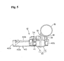
- the motorized front derailleur mounting member 32 basically includes a bicycle frame mounting portion 51, a front derailleur mounting portion 52 and a motor unit mounting portion 53.
- the bicycle frame mounting portion 51, the front derailleur mounting portion 52 and the motor unit mounting portion 53 are integrally formed as a one-piece, unitary member.
- the front derailleur mounting portion 52 and the motor unit mounting portion 53 form a derailleur motor support structure.
- the bicycle frame mounting portion 51 is configured and arranged to be coupled to the seat tube 16 of the bicycle frame 14 by the bracket 18.
- the bicycle frame mounting portion 51 includes a projection 54 that projects outwardly from a first side of the motorized front derailleur mounting member 32 to a free end that forms a curved front surface 54a with a threaded hole 54b.
- the curved front surface 54a is configured and arranged to contact a corresponding curved portion of the bracket 18 such that the motorized front derailleur mounting member 32 can not rotated relative to the bracket 18.
- One of the fasteners or bolts 19 is threaded into the threaded hole 54b of the bicycle frame mounting portion 51, while the other two fasteners or bolts 19 are threaded into the threaded holes formed the seat tube 16 such that the motorized front derailleur mounting member 32 is secured to the bicycle frame 14 via the bracket 18.
- the front derailleur mounting portion 52 is configured and arranged to be coupled to a derailleur linkage 41 of a front derailleur unit 31.
- the front derailleur mounting portion 52 has first and second link supporting parts 52a and 52b that are configured and arranged to define a link receiving space therebetween for receiving the first and second links 45 and 46.
- the first and second link supporting parts 52a and 52b are configured and arranged to form the front derailleur fixing body 42.
- the first and second link supporting parts 52a and 52b each include a first pivot pin mounting hole 52c forming the first pivot axis of the first fixed pivot point P 3 and a second pivot pin mounting hole 52d forming the second fixed pivot point P 4 .
- the first and second link supporting parts 52a and 52b are configured and arranged such that the first and second link supporting parts 52a and 52b are spaced different at the first pivot pin mounting holes 52c than at the second pivot pin mounting holes 52d to accommodate the different sizes of the first and second links 45 and 46.
- the second pivot axis of the second fixed pivot point P 4 is substantially parallel to the first pivot axis of the first fixed pivot point P 3 .
- the first pivot axis of the second pivot pin mounting holes 52d that defines the second fixed pivot point P 4 passes through the threaded hole 54b as best seen in Figure 8 .
- the motor unit mounting portion 53 is configured and arranged to be coupled to the front derailleur motor unit 33.
- the motor unit mounting portion 53 includes a plurality (three) of threaded holes 53a that form a plurality mounting parts of the motor unit mounting portion 53.
- the motor unit mounting portion 53 also includes an output shaft cutout 53b that has a center axis that is substantially parallel to the pivot axes of the first and .. second fixed pivot points P 3 and P 4 of the front derailleur mounting portion 52.
- the output shaft cutout 53b of the motor unit mounting portion 53 is a hole surrounded by material of the motor unit mounting portion 53.
- the motor unit mounting portion 53 further includes a pin mounting hole 53c in which a spring mounting pin 55 is mounted.
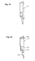
- the front derailleur motor unit 33 basically includes a derailleur motor unit support structure 61 ( Figures 2 , 7 , 36 and 39-47 ), a derailleur motor 62 ( Figures 37 and 38 ), a motor drive train 63 ( Figures 37 and 38 ), and a position control device 64 ( Figures 36 and 37 ).
- the front derailleur motor unit 33 is mounted to the motor unit mounting portion 53 that forms a derailleur motor support.
- the front derailleur motor unit 33 is operatively coupled the chain guide 40 by the motor linkage 34 and the derailleur linkage 41.
- operation of the front derailleur motor unit 33 by the shifting unit 20 causes the chain guide 40 to be shifted between the low and top shift positions.
- the derailleur motor unit support structure 61 basically includes a motor unit casing or housing 71 ( Figures 39-43 ) and a motor unit cover 72 ( Figures 44-47 ).
- the casing 71 and the cover 72 are configured and arranged to enclose and support the derailleur motor 62 and the motor drive train 63.
- the casing 71 and the cover 72 are constructed of a rigid, lightweight material such as a hard plastic material.
- the casing 71 includes a recess 71a for receiving and supporting the front derailleur motor unit 33 therein.
- the casing 71 also includes a pair of gear shaft supporting bores 71b and 71c and an output shaft hole 71d that are configured and arranged to support the motor drive train 63.
- the derailleur motor 62 is mounted to the casing 71 of the derailleur motor unit support structure 61.
- the derailleur motor 62 is a reversible electric motor that is powered by a battery source or a generator.
- the derailleur motor 62 is electrically coupled to the shifting unit 20 by an electrical cord and to a power source (battery source or generator) by another electrical cord.
- the derailleur motor 62 has a driving shaft 75 that is operatively coupled to the motor drive train 63.
- Reversible electric motors such as the derailleur motor 62 are well known. Thus, the derailleur motor 62 will not be discussed or illustrated in detail.
- the motor drive train 63 basically includes a worm gear 81, a first intermediate gear 82, a second intermediate gear 83, and an output gear 84.
- the output gear 84 is mounted on an output shaft 85.
- the motor drive train 63 transmits rotational movement of the driving shaft 75 of the derailleur motor 62 to the motor linkage 34 via the output shaft 85.
- the worm gear 81 is mounted on the driving shaft 75 of the derailleur motor 62, with the spiral tooth of the worm gear 81 engaged with a first set of teeth of the first intermediate gear 82.
- the first intermediate gear 82 has a second set of teeth that engages a first set of teeth of the second intermediate gear 83, which in turn has a second set of teeth that engages the teeth of the output gear 84.
- the output gear 84 is mounted on the output shaft 85, which in turn is coupled to the motor linkage 34.
- the motor drive train 63 is disposes between the driving shaft 75 of the derailleur motor 62 and the output shaft 85.
- the output shaft 85 is rotatably supported in the output shaft hole 71d of the casing 71 by a bearing 86.
- the bearing 86 can be mounted on the motorized derailleur mounting member 32 instead of the casing 71 such that the output shaft 85 is rotatably supported on the motorized derailleur mounting member 32.
- the output shaft 85 is configured and arranged to rotate about a rotational axis A 1 between a first rotational position and a second rotational position that is opposite the first rotational direction by rotation of the driving shaft 75 of the derailleur motor 62.
- the output shaft 85 includes an eccentric drive pin 85a having an axis A 2 that is offset from a rotational axis A 1 of the output shaft 85.
- the position control device 64 basically includes a printed circuit board 87, a position sensor element 88, a photo interrupter 89 and a top-low brush sensor 90.
- the printed circuit board 87 has a plurality of electrical circuits formed thereon in a conventional manner for controlling the operation of the derailleur motor 62 via the shifting unit 20. More specifically, the printed circuit board 87 has an electrical contact plate with electrical contact brushes 87a, 87b and 87c coupled thereto in a cantilever fashion. These brushes 87a, 87b and 87c contact the top-low brush sensor 90 that is mounted to the output gear 84. In other words, the top-low brush center 90 rotates together with the output gear 84.
- the brushes 87a, 87b and 87c selectively contact three electrical contacts.
- the brushes 87a, 87b and 87c cooperate with the contacts 90a, 90b and 90c to complete electrical circuit that drives the derailleur motor 62 in either the first rotational direction or the second (opposite) rotational direction.
- the position of the output shaft in 85 is determined by utilizing the position sensor element 88 and the photo interpreter 89.
- the photo sensor element 88 is mounted on the faced intermediate gear 82 such that the position sensor 88 rotates therewith.
- the position sensor element 88 is provided with a plurality of circumstantially spaced apart openings that are detected by the photo interpreter 89.
- the photo interpreter 89 senses the openings in the position 88 to determine the relative position of the first intermediate gear 82. Since the position of the first intermediate gear 82 directly relates to the position of the output shaft 85, the position of the output shaft 85 can easily be determined. Thus, the shifting unit 20 can determine the position of the chain guide 20 based on the relative position of the first intermediate gear 82.
- the motor linkage 34 basically includes a drive or motor link 91, a saver link 92, a saver link biasing element 93 and a position biasing element 94.
- the saver link 92 and the saver link biasing element 93 form a jamming protection arrangement.
- the motor linkage 34 is operatively coupled between the eccentric drive pin 85a of the output shaft 85 and the derailleur linkage 41. This jamming protection arrangement is configured and arranged to move between a force transmitting state and a force override state.
- the drive link 91 is configured and arranged relative to the output shaft 85 and the derailleur linkage 41 to shift the chain guide 40 between the first shift position and a second shift position.
- the drive link 91 as particularly seen in Figures 23-25 , has a first drive link end 91a and a second drive link end 91b.
- the first drive link end 91a is mounted on the eccentric drive pin 85a of the output shaft 85 such that the eccentric drive pin 85a can rotate within the holes formed in the first drive link end 91a.
- the second drive link end 91b is pivotally coupled to the saver link 92 by a pivot pin 95.
- the drive link 91 has a longitudinal axis L extending between the first and second drive link ends 91a and 91b.
- the longitudinal axis L of the drive link 91 has a first orientation ( Figures 4 and 6 ) when the chain guide 40 is in the first shift position and a second orientation ( Figures 9 and 10 ) when the chain guide 40 is in the second shift position with the first and second orientations of the longitudinal axis L of the drive link 91 being changed less than forty five degrees.
- the saver link 92 preferably has a first saver link end 92a, a second saver link end 92b and a control or stop flange 92c.
- the first saver link end 91a of the saver link 92 is pivotally coupled to the second drive link end 91b of the drive link 91 by the pivot pin 95.
- the second saver link end 92b is operatively coupled to the first or outer link 45 of the derailleur linkage 41.
- the control or stop flange 92c extends from the second saver link end 92b and is arranged to contact the top adjustment screw 49 when the motor linkage 34 is driven to the top shift position as seen in Figure 10 .
- the second or top adjustment screw 49 is configured and arranged to change the second or top shift position of the chain guide 40 relative to the fixing body 42 by the free end of the top adjustment screw 49 contacting the control or stop flange 92c of the saver link 92.
- the front derailleur unit 31 is mounted to the frame 12 by the motorized front derailleur mounting member 32 and bracket 18. Then the top shift position is set by adjusting the top adjustment screw 49 so that the chain guide 40 is disposed over the front chain wheel 22.
- This adjustment of the top shift position causes the relative orientation between the outer link 46 and the saver link 92 to change.
- the adjusting of the top adjustment screw 49 changes the relative orientation between the outer link 46 and the saver link 92 by counteracting the urging force of the saver link biasing element 93, i.e., compressing the saver link biasing element 93.
- the low shift position is also changed by the adjusting of the top adjustment screw 49 because the chain guide 40 moves with the outer link 46.
- the low position is next set by using the low adjustment screw 50, which contacts the fixing body 4, such that the chain guide 40 is disposed over the smaller front chain wheel 23.
- the adjusting of the low adjustment screw 50 changes the relative orientation between the outer link 46 and the saver link 92 when the chain guide 40 is disposed over the front chain wheel 23 by further counteracting the urging force of the saver link biasing element 93, i.e., further compressing the saver link biasing element 93.
- the saver link biasing element 93 is preferably a torsion spring having a coiled portion 93a, a first leg portion 93b and a second leg portion 93c.
- the coiled portion 93a is located about the pivot pin 47 that connects the saver link 92 to the first or outer link 45.
- the first leg portion 93b of the saver link biasing element 93 engages the saver link 92, while the second leg portion 93b contacts the first or outer link 45 of the derailleur linkage 41.
- the saver link 92 is biased in a counter clockwise direction about pivot pin 47 as viewed from the rear of the derailleur.
- the first or outer link 45 is also biased in a counterclockwise direction about the pivot pin 47 as viewed from the rear of the derailleur.
- the saver link biasing element 93 is configured and arranged to apply an urge force that normally maintains a substantially rigid connection between the drive link 91 and the derailleur linkage 41.
- the saver link 92 is pivotally coupled to the derailleur linkage 41 and the saver link biasing element 93 is operatively coupled between the saver link 92 and the derailleur linkage 41 to urge the saver link 92 from the force override state to the force transmitting state such that a substantially rigid connection is normally maintained between the saver link and the derailleur linkage 41.
- the saver link 92 and the saver link biasing element 93 form a non-rigid connection that connects a second drive link end 91b of the drive link 91 to the derailleur linkage 41.
- This non-rigid connection forms the jamming protection arrangement.
- the position biasing element 94 is preferably a tension spring that has a first end coupled to the eccentric drive pin 85a and a second end connected to the spring mounting pin 55 of the motor unit mounting portion 53.
- the position biasing element 94 is configured and arranged such that the urging force of the position biasing element 94 holds the motor linkage 34 in either the top position or the low position. In other words, when the motor linkage 34 is in the top position, the line of force of the position biasing element 94 is offset from the rotational axis A 1 of the output shaft 85 to apply a clockwise force on the output shaft 85 as viewed from the rear of the derailleur.
- the position biasing element 94 is configured and arranged to assure assist in the holding chain guide 40 in either the top or low position when the motor is no longer energized.
Landscapes
- Engineering & Computer Science (AREA)
- Chemical & Material Sciences (AREA)
- Combustion & Propulsion (AREA)
- Transportation (AREA)
- Mechanical Engineering (AREA)
- Devices For Conveying Motion By Means Of Endless Flexible Members (AREA)
- Automatic Cycles, And Cycles In General (AREA)
Claims (12)
- Befestigungselement (32) für motorisierten vorderen Umwerfer, aufweisend:einen Fahrradrahmen-Befestigungsabschnitt (51), der konfiguriert und angeordnet ist, um mit einem Sitzrohr (16) eines Fahrradrahmens (14) mittels eines Beschlages (18) verbunden zu werden;einen Befestigungsabschnitt (52) für einen vorderen Umwerfer, der konfiguriert und angeordnet ist, um mit einem Gelenkgetriebe (41) eines vorderen Umwerfers (33) verbunden zu werden, wobei der Befestigungsabschnitt für den vorderen Umwerfer mindestens einen ersten Schwenkpunkt (P3) mit einer ersten Schwenkachse beinhaltet; undeinen Motoreinheit-Befestigungsabschnitt (53), der konfiguriert und angeordnet ist, um mit einer Motoreinheit (33) verbunden zu werden,wobei der Fahrradrahmen-Befestigungsabschnitt (51), der Befestigungsabschnitt (52) für den vorderen Umwerfer und der Motoreinheit-Befestigungsabschnitt (53) integral als einstückiges unitäres Element ausgebildet sind, und dieses einen Vorsprung (54) beinhaltet, der von einer ersten Seite des Befestigungselementes (32) für den motorisierten vorderen Umwerfer zu einem freien Ende nach außen vorsteht, das eine gekrümmte Vorderfläche (54a) bildet,dadurch gekennzeichnet, dass die gekrümmte Vorderfläche (54a) des Rahmenbefestigungsabschnitts (51) ein Gewindeloch (54b) aufweist, und konfiguriert und angeordnet ist, um mit einem entsprechenden gekrümmten Abschnitt des Beschlags (18) in Kontakt zu kommen, derart, dass das Befestigungselement (32) für den motorisierten vorderen Umwerfer nicht relativ zum Beschlag (18) rotieren kann.
- Befestigungselement für motorisierten vorderen Umwerfer nach Anspruch 1, wobei der Motoreinheit-Befestigungsabschnitt (53) eine Abtriebswellen-Aussparung (53b) beinhaltet, die eine Mittelachse aufweist, die im Wesentlichen parallel zur ersten Schwenkachse des ersten Schwenkpunkts (P3) des Befestigungsabschnittes (52) für den vorderen Umwerfer ist.
- Befestigungselement für motorisierten vorderen Umwerfer nach Anspruch 2, wobei das Gewindeloch (54b) des Fahrradrahmen-Befestigungsabschnitts eine Längsachse beinhaltet, die im Wesentlichen parallel zur Mittelachse der Abtriebswellen-Aussparung (53b) des Motoreinheit-Befestigungsabschnitts (53) ist.
- Befestigungselement für motorisierten vorderen Umwerfer nach Anspruch 3, wobei
die Abtriebswellen-Aussparung (53b) des Motoreinheit-Befestigungsabschnitts (53) ein Loch ist, das von Material des Motoreinheit-Befestigungsabschnitts umgeben ist. - Befestigungselement für motorisierten vorderen Umwerfer nach Anspruch 4, wobei
der Befestigungsabschnitt (52) für den vorderen Umwerfer einen zweiten Schwenkpunkt (P4) mit einer zweiten Schwenkachse beinhaltet, die im Wesentlichen parallel zur ersten Schwenkachse des ersten Schwenkpunktes (P3) ist. - Befestigungselement für motorisierten vorderen Umwerfer nach Anspruch 1, wobei
der Motoreinheit-Befestigungsabschnitt (53) weiter eine Mehrzahl von Befestigungsteilen (53a) beinhaltet. - Befestigungselement für motorisierten vorderen Umwerfer nach Anspruch 6, wobei
die Befestigungsteile (53a) des Motoreinheit-Befestigungsabschnitts 853) Gewindelöcher sind. - Befestigungselement für motorisierten vorderen Umwerfer nach Anspruch 5, wobei
der Befestigungsabschnitt (52) für den vorderen Umwerfer konfiguriert und angeordnet ist, um einen Befestigungskörper (42) zu bilden, der erste und zweite Gelenkstück-Trägerteile (52a, 52b) aufweist, die konfiguriert und angeordnet sind, um einen Gelenkstück-Aufnahmeraum zwischen sich zu begrenzen. - Befestigungselement für motorisierten vorderen Umwerfer nach Anspruch 8, wobei
die ersten und zweiten Gelenkstück-Trägerteile (52a, 52b) jeweils ein erstes Schwenkstift-Befestigungsloch (52c), das die erste Schwenkachse des ersten Schwenkpunktes (P3) bildet, und ein zweites Schwenkstift-Befestigungsloch (52d) aufweist, welches den zweiten Schwenkpunkt (P4) bildet. - Befestigungselement für motorisierten vorderen Umwerfer nach Anspruch 9, wobei
die ersten und zweiten Gelenkstück-Trägerteile (52a, 52b) derart konfiguriert und angeordnet sind, dass die ersten und zweiten Gelenkstück-Trägerteile unterschiedlich beabstandet beim ersten Schwenkstift-Befestigungsloch (52c) sind als beim zweiten Schwenkstift-Befestigungsloch (52d). - Befestigungselement für motorisierten vorderen Umwerfer nach Anspruch 1, wobei
die erste Schwenkachse des ersten Schwenkpunktes (P3) durch das Gewindeloch (54b) hindurch verläuft. - Motorisierte vordere Umwerferbaugruppe, aufweisend:das Befestigungselement (32) für den motorisierten vorderen Umwerfer nach Anspruch 8;eine Kettenführung (40), die erste und zweite bewegte Schwenkpunkte (P1, P2) aufweist;ein erstes Gelenkstück (45), dessen erstes Ende mit dem ersten feststehenden Schwenkpunkt (P3) des Befestigungskörpers (42) schwenkbar verbunden ist und dessen zweites Ende mit dem ersten bewegten Punkt (P1) der Kettenführung (40) schwenkbar verbunden ist; undein zweites Gelenkstück (46), dessen erstes Ende mit dem zweiten feststehenden Schwenkpunkt (P4) des Befestigungskörpers (42) schwenkbar verbunden ist und dessen zweites Ende mit dem zweiten bewegten Punkt (P2) der Kettenführung (40) schwenkbar verbunden ist.
Applications Claiming Priority (2)
| Application Number | Priority Date | Filing Date | Title |
|---|---|---|---|
| US786153 | 1997-01-21 | ||
| US10/786,153 US7331890B2 (en) | 2004-02-26 | 2004-02-26 | Motorized front derailleur mounting member |
Publications (3)
| Publication Number | Publication Date |
|---|---|
| EP1568588A2 EP1568588A2 (de) | 2005-08-31 |
| EP1568588A3 EP1568588A3 (de) | 2006-09-06 |
| EP1568588B1 true EP1568588B1 (de) | 2009-09-23 |
Family
ID=34750481
Family Applications (1)
| Application Number | Title | Priority Date | Filing Date |
|---|---|---|---|
| EP04029086A Revoked EP1568588B1 (de) | 2004-02-26 | 2004-12-08 | Motorisierte vordere Gangschaltung Halterung |
Country Status (6)
| Country | Link |
|---|---|
| US (1) | US7331890B2 (de) |
| EP (1) | EP1568588B1 (de) |
| JP (1) | JP2005239137A (de) |
| CN (1) | CN1660647A (de) |
| DE (1) | DE602004023266D1 (de) |
| TW (1) | TWI241264B (de) |
Families Citing this family (36)
| Publication number | Priority date | Publication date | Assignee | Title |
|---|---|---|---|---|
| US7438658B2 (en) * | 2004-08-30 | 2008-10-21 | Shimano Inc. | Bicycle front derailleur |
| US7503863B2 (en) * | 2005-02-18 | 2009-03-17 | Shimano Inc. | Bicycle derailleur motor unit assembly |
| US7704173B2 (en) * | 2006-02-08 | 2010-04-27 | Shimano Inc. | Motorized bicycle derailleur assembly |
| ITMI20070883A1 (it) * | 2007-05-03 | 2008-11-04 | Campagnolo Srl | Deragliatore anteriore per una bicicletta |
| ITMI20072062A1 (it) * | 2007-10-25 | 2009-04-26 | Campagnolo Srl | Cambio di bicicletta |
| WO2010033212A1 (en) * | 2008-09-18 | 2010-03-25 | Wickwerks, Llc | Six link front derailleur |
| US9327792B2 (en) * | 2011-01-28 | 2016-05-03 | Paha Designs, Llc | Gear transmission and derailleur system |
| US10207772B2 (en) * | 2011-01-28 | 2019-02-19 | Paha Designs, Llc | Gear transmission and derailleur system |
| US8974331B2 (en) * | 2012-12-10 | 2015-03-10 | Shimano Inc. | Bicycle derailleur |
| US9890838B2 (en) * | 2012-10-18 | 2018-02-13 | Sram, Llc | Front gear changer |
| US8888620B2 (en) * | 2012-12-05 | 2014-11-18 | Shimano Inc. | Front derailleur |
| US8864611B2 (en) * | 2012-12-05 | 2014-10-21 | Shimano Inc. | Front derailleur |
| ITMI20130299A1 (it) * | 2013-02-28 | 2014-08-29 | Campagnolo Srl | Deragliatore di bicicletta, particolarmente deragliatore anteriore, ad affidabilità migliorata |
| JP2014213705A (ja) * | 2013-04-25 | 2014-11-17 | 株式会社シマノ | 自転車用のディレーラ |
| JP2015016792A (ja) * | 2013-07-11 | 2015-01-29 | 株式会社シマノ | フロントディレーラ |
| US9248885B2 (en) * | 2013-09-30 | 2016-02-02 | Shimano Inc. | Derailleur |
| US9676444B2 (en) * | 2013-10-23 | 2017-06-13 | Sram, Llc | Electromechanical rear derailleur |
| US9085340B1 (en) * | 2014-03-14 | 2015-07-21 | Tien Hsin Industries Co., Ltd. | Electronic front derailleur |
| US9555857B2 (en) * | 2014-06-04 | 2017-01-31 | Shimano Inc. | Bicycle front derailleur |
| DE202015005016U1 (de) | 2015-07-17 | 2015-08-20 | Sram Deutschland Gmbh | Vorderes Schaltwerk |
| US9873482B2 (en) * | 2015-10-09 | 2018-01-23 | Shimano Inc. | Bicycle front derailleur |
| CN106809337A (zh) * | 2015-11-30 | 2017-06-09 | 潘百鸣 | 适合右利足人群使用的左驱动变速自行车 |
| CN107042867B (zh) * | 2016-02-05 | 2020-10-09 | 禧玛诺(新)私人有限公司 | 自行车前拨链器 |
| US10086905B2 (en) * | 2016-03-22 | 2018-10-02 | Shimano Inc. | Bicycle front derailleur with mounting bracket |
| IT201600069087A1 (it) * | 2016-07-04 | 2018-01-04 | Campagnolo Srl | Deragliatore elettrico anteriore di bicicletta |
| IT201700018702A1 (it) * | 2017-02-20 | 2018-08-20 | Campagnolo Srl | Deragliatore elettrico posteriore di bicicletta |
| TWI723397B (zh) * | 2019-03-19 | 2021-04-01 | 彥豪金屬工業股份有限公司 | 自行車後變速器 |
| US11192607B2 (en) * | 2019-05-30 | 2021-12-07 | Shimano Inc. | Electric front derailleur |
| TWI718791B (zh) * | 2019-11-29 | 2021-02-11 | 彥豪金屬工業股份有限公司 | 自行車前變速器 |
| US11697474B2 (en) * | 2020-06-30 | 2023-07-11 | Shimano Inc. | Bicycle derailleur and link pin for bicycle derailleur |
| US11745828B2 (en) | 2020-06-30 | 2023-09-05 | Shimano Inc. | Front derailleur and chain guide of bicycle derailleur |
| US11565772B2 (en) * | 2020-06-30 | 2023-01-31 | Shimano Inc. | Bicycle derailleur, bicycle gear structure, bicycle motor unit, and front derailleur |
| US11685469B2 (en) * | 2020-09-11 | 2023-06-27 | Shimano Inc. | Bicycle derailleur |
| US11787506B2 (en) * | 2021-03-30 | 2023-10-17 | Shimano Inc. | Derailleur for human-powered vehicle |
| US12240562B2 (en) * | 2021-06-30 | 2025-03-04 | Shimano (Singapore) Pte. Ltd. | Derailleur for human-powered vehicle |
| US11794856B2 (en) * | 2023-02-14 | 2023-10-24 | Hazem Nihad Hamed | Front derailleur electrical actuator |
Family Cites Families (33)
| Publication number | Priority date | Publication date | Assignee | Title |
|---|---|---|---|---|
| US3919891A (en) | 1973-10-15 | 1975-11-18 | Brian J Stuhlmuller | Electrical gear changer for chain driven vehicle |
| JPS53102550A (en) * | 1977-02-21 | 1978-09-06 | Shimano Industrial Co | Front derailer |
| US5213548A (en) | 1992-03-02 | 1993-05-25 | Colbert Ralph G | Gear shifting system for derailleur equipped bicycle |
| IT1261090B (it) | 1993-07-08 | 1996-05-08 | Antonio Romano | Gruppo di cambio di velocita' motorizzato per biciclette. |
| JP3470820B2 (ja) | 1993-10-06 | 2003-11-25 | 株式会社シマノ | 自転車用変速装置 |
| DE4340471C1 (de) | 1993-11-27 | 1995-02-02 | Fichtel & Sachs Ag | Kettenschaltung für Fahrräder |
| JP3372616B2 (ja) | 1993-11-30 | 2003-02-04 | 株式会社シマノ | 自転車用ディレーラ |
| US5514041A (en) | 1994-11-21 | 1996-05-07 | Hsu; Yi-Hsung | Electronic bicycle derailleur control apparatus |
| JP3328113B2 (ja) * | 1995-08-07 | 2002-09-24 | 株式会社シマノ | 自転車のフロントディレーラ |
| US5599244A (en) | 1995-08-14 | 1997-02-04 | Ethington; Russell A. | Automatic transmission shifter for velocipedes |
| DE29513967U1 (de) | 1995-08-31 | 1997-01-16 | Hessabi, Iradj, Dipl.-Ing., 33813 Oerlinghausen | Säge-, Schneide-, Trennvorrichtung |
| US5860880A (en) | 1996-11-21 | 1999-01-19 | Shimano, Inc. | Low normal bicycle derailleur which allows lateral movement of the chain guide toward the rear wheel in response to a force directed laterally towards the rear wheel |
| US5873283A (en) | 1997-01-14 | 1999-02-23 | Chen; Cheng Hsiung | Motorized control for a derailleur |
| US6282976B1 (en) | 1997-02-20 | 2001-09-04 | Sram Corporation | Discontinuous mechanical advantage front shifting for bicycles |
| JP3474080B2 (ja) | 1997-05-16 | 2003-12-08 | 株式会社シマノ | 自転車用スイッチ |
| US6162140A (en) | 1998-12-18 | 2000-12-19 | Shimano, Inc. | Motor driven derailleur |
| US6296072B1 (en) | 1999-01-20 | 2001-10-02 | Opti-Bike Llc | Electric bicycle and methods |
| US6146298A (en) * | 1999-03-29 | 2000-11-14 | Shimano, Inc. | Band adapter for front derailleur |
| US6212078B1 (en) | 1999-10-27 | 2001-04-03 | Microcoating Technologies | Nanolaminated thin film circuitry materials |
| IT1310731B1 (it) | 1999-11-23 | 2002-02-22 | Campagnolo Srl | Dispositivo di cambio di velocita' per biciclette. |
| CN100335357C (zh) | 1999-12-30 | 2007-09-05 | 株式会社岛野 | 自行车毂盘变速器用曲拐 |
| US6629903B1 (en) * | 2000-04-17 | 2003-10-07 | Shimano Inc. | Bicycle derailleur |
| IT1320405B1 (it) | 2000-06-06 | 2003-11-26 | Campagnolo Srl | Dispositivo di comando elettrico per un deragliatore motorizzato perbiciclette. |
| JP2002000765A (ja) * | 2000-06-26 | 2002-01-08 | Bridgestone Sports Co Ltd | ゴルフボール |
| IT1320581B1 (it) * | 2000-08-03 | 2003-12-10 | Campagnolo Srl | Deragliatore anteriore di bicicletta con motore elettrico di comando e riduttore ad ingranaggi. |
| IT1321071B1 (it) | 2000-11-17 | 2003-12-30 | Campagnolo Srl | Dispositivo attuatore per un deragliatore di bicicletta, con giunto di collegamento all'albero condotto. |
| US6767308B2 (en) | 2001-03-09 | 2004-07-27 | Shimano Inc. | Method of controlling bicycle assembly |
| US6726586B2 (en) | 2001-11-09 | 2004-04-27 | Shimano Inc. | Motorized bicycle actuator assembly |
| ATE383304T1 (de) | 2002-04-26 | 2008-01-15 | Campagnolo Srl | Fahrradgangschaltung |
| JP3645876B2 (ja) | 2002-08-30 | 2005-05-11 | 株式会社シマノ | 自転車用電装品制御装置 |
| US7014584B2 (en) * | 2002-12-27 | 2006-03-21 | Shimano Inc. | Top pull type front derailleur |
| US7081058B2 (en) * | 2003-02-12 | 2006-07-25 | Shimano Inc. | Bicycle front derailleur |
| US6902503B2 (en) * | 2003-02-27 | 2005-06-07 | Shimano Inc. | Bicycle derailleur |
-
2004
- 2004-02-26 US US10/786,153 patent/US7331890B2/en not_active Expired - Lifetime
- 2004-09-08 TW TW093127167A patent/TWI241264B/zh not_active IP Right Cessation
- 2004-12-08 EP EP04029086A patent/EP1568588B1/de not_active Revoked
- 2004-12-08 DE DE602004023266T patent/DE602004023266D1/de not_active Expired - Lifetime
- 2004-12-30 CN CN2004101037067A patent/CN1660647A/zh active Pending
-
2005
- 2005-02-17 JP JP2005040481A patent/JP2005239137A/ja not_active Withdrawn
Also Published As
| Publication number | Publication date |
|---|---|
| US20050192137A1 (en) | 2005-09-01 |
| US7331890B2 (en) | 2008-02-19 |
| EP1568588A2 (de) | 2005-08-31 |
| EP1568588A3 (de) | 2006-09-06 |
| DE602004023266D1 (de) | 2009-11-05 |
| JP2005239137A (ja) | 2005-09-08 |
| CN1660647A (zh) | 2005-08-31 |
| TW200528337A (en) | 2005-09-01 |
| TWI241264B (en) | 2005-10-11 |
Similar Documents
| Publication | Publication Date | Title |
|---|---|---|
| EP1568588B1 (de) | Motorisierte vordere Gangschaltung Halterung | |
| EP1568590B1 (de) | Motorgetriebene Vorderkettenschaltungsanordnung | |
| EP1568589B1 (de) | Motorisierte Fahrradgangschaltung | |
| EP1568594B1 (de) | Motoreinheit einer elektrischen Fahrradgangschaltung | |
| US20050197222A1 (en) | Front derailleur motor unit assembly | |
| EP1818253B1 (de) | Motorgesteuerter Fahrrad-Gangumwerfer | |
| EP1693294B1 (de) | Motorgesteuerter Fahrrad-Gangumwerfer | |
| US7503863B2 (en) | Bicycle derailleur motor unit assembly | |
| EP1588934B1 (de) | Elektrisch gesteuertes Fahrradgetriebe |
Legal Events
| Date | Code | Title | Description |
|---|---|---|---|
| PUAI | Public reference made under article 153(3) epc to a published international application that has entered the european phase |
Free format text: ORIGINAL CODE: 0009012 |
|
| AK | Designated contracting states |
Kind code of ref document: A2 Designated state(s): AT BE BG CH CY CZ DE DK EE ES FI FR GB GR HU IE IS IT LI LT LU MC NL PL PT RO SE SI SK TR |
|
| AX | Request for extension of the european patent |
Extension state: AL BA HR LV MK YU |
|
| RAP1 | Party data changed (applicant data changed or rights of an application transferred) |
Owner name: SHIMANO INC. |
|
| PUAL | Search report despatched |
Free format text: ORIGINAL CODE: 0009013 |
|
| AK | Designated contracting states |
Kind code of ref document: A3 Designated state(s): AT BE BG CH CY CZ DE DK EE ES FI FR GB GR HU IE IS IT LI LT LU MC NL PL PT RO SE SI SK TR |
|
| AX | Request for extension of the european patent |
Extension state: AL BA HR LV MK YU |
|
| 17P | Request for examination filed |
Effective date: 20060928 |
|
| 17Q | First examination report despatched |
Effective date: 20061128 |
|
| AKX | Designation fees paid |
Designated state(s): DE FR IT |
|
| GRAP | Despatch of communication of intention to grant a patent |
Free format text: ORIGINAL CODE: EPIDOSNIGR1 |
|
| GRAS | Grant fee paid |
Free format text: ORIGINAL CODE: EPIDOSNIGR3 |
|
| GRAA | (expected) grant |
Free format text: ORIGINAL CODE: 0009210 |
|
| AK | Designated contracting states |
Kind code of ref document: B1 Designated state(s): DE FR IT |
|
| REF | Corresponds to: |
Ref document number: 602004023266 Country of ref document: DE Date of ref document: 20091105 Kind code of ref document: P |
|
| PLBI | Opposition filed |
Free format text: ORIGINAL CODE: 0009260 |
|
| PLAX | Notice of opposition and request to file observation + time limit sent |
Free format text: ORIGINAL CODE: EPIDOSNOBS2 |
|
| 26 | Opposition filed |
Opponent name: SRAM DEUTSCHLAND GMBH Effective date: 20100623 |
|
| PLAF | Information modified related to communication of a notice of opposition and request to file observations + time limit |
Free format text: ORIGINAL CODE: EPIDOSCOBS2 |
|
| PLBB | Reply of patent proprietor to notice(s) of opposition received |
Free format text: ORIGINAL CODE: EPIDOSNOBS3 |
|
| REG | Reference to a national code |
Ref country code: FR Ref legal event code: PLFP Year of fee payment: 12 |
|
| APBM | Appeal reference recorded |
Free format text: ORIGINAL CODE: EPIDOSNREFNO |
|
| APBP | Date of receipt of notice of appeal recorded |
Free format text: ORIGINAL CODE: EPIDOSNNOA2O |
|
| APAH | Appeal reference modified |
Free format text: ORIGINAL CODE: EPIDOSCREFNO |
|
| APBM | Appeal reference recorded |
Free format text: ORIGINAL CODE: EPIDOSNREFNO |
|
| APBP | Date of receipt of notice of appeal recorded |
Free format text: ORIGINAL CODE: EPIDOSNNOA2O |
|
| APBQ | Date of receipt of statement of grounds of appeal recorded |
Free format text: ORIGINAL CODE: EPIDOSNNOA3O |
|
| APBQ | Date of receipt of statement of grounds of appeal recorded |
Free format text: ORIGINAL CODE: EPIDOSNNOA3O |
|
| REG | Reference to a national code |
Ref country code: FR Ref legal event code: PLFP Year of fee payment: 13 |
|
| PGFP | Annual fee paid to national office [announced via postgrant information from national office to epo] |
Ref country code: FR Payment date: 20161111 Year of fee payment: 13 |
|
| PGFP | Annual fee paid to national office [announced via postgrant information from national office to epo] |
Ref country code: IT Payment date: 20161221 Year of fee payment: 13 |
|
| REG | Reference to a national code |
Ref country code: FR Ref legal event code: ST Effective date: 20180831 |
|
| PG25 | Lapsed in a contracting state [announced via postgrant information from national office to epo] |
Ref country code: IT Free format text: LAPSE BECAUSE OF NON-PAYMENT OF DUE FEES Effective date: 20171208 Ref country code: FR Free format text: LAPSE BECAUSE OF NON-PAYMENT OF DUE FEES Effective date: 20180102 |
|
| PGFP | Annual fee paid to national office [announced via postgrant information from national office to epo] |
Ref country code: DE Payment date: 20181127 Year of fee payment: 15 |
|
| REG | Reference to a national code |
Ref country code: DE Ref legal event code: R064 Ref document number: 602004023266 Country of ref document: DE Ref country code: DE Ref legal event code: R103 Ref document number: 602004023266 Country of ref document: DE |
|
| APBU | Appeal procedure closed |
Free format text: ORIGINAL CODE: EPIDOSNNOA9O |
|
| RDAF | Communication despatched that patent is revoked |
Free format text: ORIGINAL CODE: EPIDOSNREV1 |
|
| STAA | Information on the status of an ep patent application or granted ep patent |
Free format text: STATUS: PATENT REVOKED |
|
| RDAG | Patent revoked |
Free format text: ORIGINAL CODE: 0009271 |
|
| 27W | Patent revoked |
Effective date: 20190723 |