EP1568560A2 - Vehicle liftgate window component module - Google Patents
Vehicle liftgate window component module Download PDFInfo
- Publication number
- EP1568560A2 EP1568560A2 EP05004014A EP05004014A EP1568560A2 EP 1568560 A2 EP1568560 A2 EP 1568560A2 EP 05004014 A EP05004014 A EP 05004014A EP 05004014 A EP05004014 A EP 05004014A EP 1568560 A2 EP1568560 A2 EP 1568560A2
- Authority
- EP
- European Patent Office
- Prior art keywords
- window
- liftgate
- latch
- module
- handle
- Prior art date
- Legal status (The legal status is an assumption and is not a legal conclusion. Google has not performed a legal analysis and makes no representation as to the accuracy of the status listed.)
- Withdrawn
Links
- 230000005540 biological transmission Effects 0.000 claims 1
- 230000004044 response Effects 0.000 abstract description 11
- 230000004913 activation Effects 0.000 abstract description 8
- 239000011521 glass Substances 0.000 description 14
- 210000000078 claw Anatomy 0.000 description 11
- 239000012528 membrane Substances 0.000 description 4
- 239000004020 conductor Substances 0.000 description 3
- 238000004519 manufacturing process Methods 0.000 description 3
- 230000013011 mating Effects 0.000 description 3
- AAOVKJBEBIDNHE-UHFFFAOYSA-N diazepam Chemical compound N=1CC(=O)N(C)C2=CC=C(Cl)C=C2C=1C1=CC=CC=C1 AAOVKJBEBIDNHE-UHFFFAOYSA-N 0.000 description 2
- 230000007246 mechanism Effects 0.000 description 2
- 239000002184 metal Substances 0.000 description 2
- 238000000034 method Methods 0.000 description 2
- 229920000642 polymer Polymers 0.000 description 2
- 239000012858 resilient material Substances 0.000 description 2
- 125000006850 spacer group Chemical group 0.000 description 2
- 230000003213 activating effect Effects 0.000 description 1
- 239000000853 adhesive Substances 0.000 description 1
- 230000001070 adhesive effect Effects 0.000 description 1
- 230000003466 anti-cipated effect Effects 0.000 description 1
- 230000008859 change Effects 0.000 description 1
- 230000006835 compression Effects 0.000 description 1
- 238000007906 compression Methods 0.000 description 1
- 238000010276 construction Methods 0.000 description 1
- 230000007547 defect Effects 0.000 description 1
- 238000010586 diagram Methods 0.000 description 1
- 230000009977 dual effect Effects 0.000 description 1
- 230000002349 favourable effect Effects 0.000 description 1
- 239000011152 fibreglass Substances 0.000 description 1
- 238000009434 installation Methods 0.000 description 1
- 238000007789 sealing Methods 0.000 description 1
Images


Classifications
-
- B—PERFORMING OPERATIONS; TRANSPORTING
- B60—VEHICLES IN GENERAL
- B60S—SERVICING, CLEANING, REPAIRING, SUPPORTING, LIFTING, OR MANOEUVRING OF VEHICLES, NOT OTHERWISE PROVIDED FOR
- B60S1/00—Cleaning of vehicles
- B60S1/02—Cleaning windscreens, windows or optical devices
- B60S1/56—Cleaning windscreens, windows or optical devices specially adapted for cleaning other parts or devices than front windows or windscreens
- B60S1/58—Cleaning windscreens, windows or optical devices specially adapted for cleaning other parts or devices than front windows or windscreens for rear windows
- B60S1/583—Cleaning windscreens, windows or optical devices specially adapted for cleaning other parts or devices than front windows or windscreens for rear windows including wiping devices
-
- B—PERFORMING OPERATIONS; TRANSPORTING
- B60—VEHICLES IN GENERAL
- B60J—WINDOWS, WINDSCREENS, NON-FIXED ROOFS, DOORS, OR SIMILAR DEVICES FOR VEHICLES; REMOVABLE EXTERNAL PROTECTIVE COVERINGS SPECIALLY ADAPTED FOR VEHICLES
- B60J1/00—Windows; Windscreens; Accessories therefor
- B60J1/18—Windows; Windscreens; Accessories therefor arranged at the vehicle rear
- B60J1/1838—Windows; Windscreens; Accessories therefor arranged at the vehicle rear movable for non-convertible vehicles, including vehicles with versatile load area
- B60J1/1876—Windows; Windscreens; Accessories therefor arranged at the vehicle rear movable for non-convertible vehicles, including vehicles with versatile load area where the window is pivotable relative to a stationary axis
- B60J1/1884—Windows; Windscreens; Accessories therefor arranged at the vehicle rear movable for non-convertible vehicles, including vehicles with versatile load area where the window is pivotable relative to a stationary axis about a horizontal axis
-
- E—FIXED CONSTRUCTIONS
- E05—LOCKS; KEYS; WINDOW OR DOOR FITTINGS; SAFES
- E05B—LOCKS; ACCESSORIES THEREFOR; HANDCUFFS
- E05B83/00—Vehicle locks specially adapted for particular types of wing or vehicle
- E05B83/16—Locks for luggage compartments, car boot lids or car bonnets
-
- B—PERFORMING OPERATIONS; TRANSPORTING
- B60—VEHICLES IN GENERAL
- B60S—SERVICING, CLEANING, REPAIRING, SUPPORTING, LIFTING, OR MANOEUVRING OF VEHICLES, NOT OTHERWISE PROVIDED FOR
- B60S1/00—Cleaning of vehicles
- B60S1/02—Cleaning windscreens, windows or optical devices
- B60S1/04—Wipers or the like, e.g. scrapers
- B60S1/0413—Modular wiper assembly
- B60S1/0416—Modular wiper assembly including other vehicle fittings
-
- B—PERFORMING OPERATIONS; TRANSPORTING
- B60—VEHICLES IN GENERAL
- B60S—SERVICING, CLEANING, REPAIRING, SUPPORTING, LIFTING, OR MANOEUVRING OF VEHICLES, NOT OTHERWISE PROVIDED FOR
- B60S1/00—Cleaning of vehicles
- B60S1/02—Cleaning windscreens, windows or optical devices
- B60S1/04—Wipers or the like, e.g. scrapers
- B60S1/043—Attachment of the wiper assembly to the vehicle
- B60S1/0438—Attachement of separate wiper motor assembly to the vehicle
-
- B—PERFORMING OPERATIONS; TRANSPORTING
- B60—VEHICLES IN GENERAL
- B60S—SERVICING, CLEANING, REPAIRING, SUPPORTING, LIFTING, OR MANOEUVRING OF VEHICLES, NOT OTHERWISE PROVIDED FOR
- B60S1/00—Cleaning of vehicles
- B60S1/02—Cleaning windscreens, windows or optical devices
- B60S1/04—Wipers or the like, e.g. scrapers
- B60S1/043—Attachment of the wiper assembly to the vehicle
- B60S1/0441—Attachment of the wiper assembly to the vehicle characterised by the attachment means
- B60S1/0444—Attachment of the wiper assembly to the vehicle characterised by the attachment means comprising vibration or noise absorbing means
-
- B—PERFORMING OPERATIONS; TRANSPORTING
- B60—VEHICLES IN GENERAL
- B60S—SERVICING, CLEANING, REPAIRING, SUPPORTING, LIFTING, OR MANOEUVRING OF VEHICLES, NOT OTHERWISE PROVIDED FOR
- B60S1/00—Cleaning of vehicles
- B60S1/02—Cleaning windscreens, windows or optical devices
- B60S1/04—Wipers or the like, e.g. scrapers
- B60S1/0491—Additional elements being fixed on wipers or parts of wipers not otherwise provided for, e.g. covers, antennae or lights
-
- E—FIXED CONSTRUCTIONS
- E05—LOCKS; KEYS; WINDOW OR DOOR FITTINGS; SAFES
- E05B—LOCKS; ACCESSORIES THEREFOR; HANDCUFFS
- E05B81/00—Power-actuated vehicle locks
- E05B81/12—Power-actuated vehicle locks characterised by the function or purpose of the powered actuators
- E05B81/13—Power-actuated vehicle locks characterised by the function or purpose of the powered actuators a single actuator for driving a lock and additional vehicle components, e.g. window wipers or window lifters
-
- E—FIXED CONSTRUCTIONS
- E05—LOCKS; KEYS; WINDOW OR DOOR FITTINGS; SAFES
- E05B—LOCKS; ACCESSORIES THEREFOR; HANDCUFFS
- E05B81/00—Power-actuated vehicle locks
- E05B81/12—Power-actuated vehicle locks characterised by the function or purpose of the powered actuators
- E05B81/14—Power-actuated vehicle locks characterised by the function or purpose of the powered actuators operating on bolt detents, e.g. for unlatching the bolt
-
- Y—GENERAL TAGGING OF NEW TECHNOLOGICAL DEVELOPMENTS; GENERAL TAGGING OF CROSS-SECTIONAL TECHNOLOGIES SPANNING OVER SEVERAL SECTIONS OF THE IPC; TECHNICAL SUBJECTS COVERED BY FORMER USPC CROSS-REFERENCE ART COLLECTIONS [XRACs] AND DIGESTS
- Y10—TECHNICAL SUBJECTS COVERED BY FORMER USPC
- Y10T—TECHNICAL SUBJECTS COVERED BY FORMER US CLASSIFICATION
- Y10T292/00—Closure fasteners
- Y10T292/68—Keepers
- Y10T292/696—With movable dog, catch or striker
Landscapes
- Engineering & Computer Science (AREA)
- Mechanical Engineering (AREA)
- Power-Operated Mechanisms For Wings (AREA)
- Window Of Vehicle (AREA)
Abstract
Description
Claims (11)
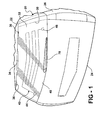
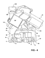
- A liftgate component module mountable on a movable liftgate window carried on a vehicle liftgate, the module comprising:a window wiper drive means for reciprocating a wiper arm;a window latch means for releasably latching a liftgate window to a liftgate;means for unitarily joining the wiper drive means and window latch means to the liftgate window; andhandle means mounted to the liftgate window, the handle means operative to effect release of the latch means for opening movement of the window relative to the liftgate.
- The module of claim 1 wherein the handle means comprises:electrical handle means for generating a window latch release signal when activated.
- The module of claim 2 further comprising:control means carried on one of the joined wiper drive means and window latch means and responsive to the window latch release signal for controlling the window latch means; andthe window latch means release signals from the electrical handle connected from the handle to the control means.
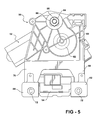
- The module of claim 1 further comprising:a plurality of mounting flanges carried on the joined wiper drive means and window latch means;apertures formed in each of the plurality of mounting flanges for receiving fasteners for mounting the wiper drive means and the window latch means on window.
- The module of claim 4 further comprising:dampening members coupled between the flanges and the wiper drive motor to vibrationally isolate the wiper drive motor from the window.
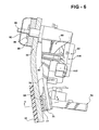
- The module of claim 4 further comprising:a fastener extending through the aperture in the mounting flange to the motor and the latch to join a portion of the motor and the latch to the window.
- The module of claim 6 wherein:at least one of the mounting flanges is unitary with the latch means.
- The module of claim 1 wherein:the drive means, including a drive motor and a gear transmission, and the window latch means orientated substantially linearly with respect to a bottom edge of the liftgate window.
- The module of claim 1 wherein:the wiper drive means has a rotatable output shaft extending through an aperture in the window; anda window wiper and the handle means mounted about the output shaft exteriorly of the liftgate, the wiper arm fixed to the output shaft for common rotation of the wiper arm and output shaft.
- A liftgate component apparatus mountable on a liftgate, the apparatus comprising:a window wiper drive means for reciprocating a wiper arm;a window latch means for releasably latching a liftgate window to a liftgate;a liftgate latch means for releasably latching a liftgate to a vehicle;electrical handle means for generating a window latch release signal when activated;electrical handle means for generating a liftgate latch release signal when activated; andcontrol means, carried on the liftgate, and responsive to the window latch release signal and the liftgate latch release signal, for controlling the operation of the window latch and the liftgate latch.
- The apparatus of claim 10 wherein:the control means is responsive to external signals for controlling the window wiper drive means.
Applications Claiming Priority (4)
| Application Number | Priority Date | Filing Date | Title |
|---|---|---|---|
| US54721404P | 2004-02-24 | 2004-02-24 | |
| US547214P | 2004-02-24 | ||
| US862266 | 2004-06-07 | ||
| US10/862,266 US7246840B2 (en) | 2003-01-31 | 2004-06-07 | Vehicle liftgate window component module |
Publications (2)
| Publication Number | Publication Date |
|---|---|
| EP1568560A2 true EP1568560A2 (en) | 2005-08-31 |
| EP1568560A3 EP1568560A3 (en) | 2007-09-26 |
Family
ID=34753141
Family Applications (1)
| Application Number | Title | Priority Date | Filing Date |
|---|---|---|---|
| EP20050004014 Withdrawn EP1568560A3 (en) | 2004-02-24 | 2005-02-24 | Vehicle liftgate window component module |
Country Status (2)
| Country | Link |
|---|---|
| US (1) | US7246840B2 (en) |
| EP (1) | EP1568560A3 (en) |
Cited By (6)
| Publication number | Priority date | Publication date | Assignee | Title |
|---|---|---|---|---|
| FR2899188A1 (en) * | 2006-03-31 | 2007-10-05 | Valeo Systemes Dessuyage | Lock and windshield wiper motor module for motor vehicle, has lock and windshield wiper arm driving system`s swivel pin that are centered on longitudinal central axis of vehicle, and motor that is off centered with respect to axis |
| WO2008065080A1 (en) * | 2006-11-30 | 2008-06-05 | Valeo Systemes D'essuyage | Arrangement of a switch on an opening panel of a motor vehicle |
| EP2082908A1 (en) * | 2008-01-24 | 2009-07-29 | GM Global Technology Operations, Inc. | Actuating device |
| FR2966409A1 (en) * | 2010-10-26 | 2012-04-27 | Peugeot Citroen Automobiles Sa | Windscreen wiper mechanism for cleaning e.g. front windscreen, of motor vehicle in rainy condition, has bearing that is provided with clamping unit for receiving electrical cable that is to be clamped relative to bearing |
| DE102013101739A1 (en) | 2013-02-21 | 2014-08-21 | Dr. Ing. H.C. F. Porsche Aktiengesellschaft | Device for activating opening- or locking of tailgate of vehicle, has cover that is designed in relation to rear window wiper shaft, so that cable duct extends in vehicle interior |
| FR3050968A1 (en) * | 2016-05-09 | 2017-11-10 | Peugeot Citroen Automobiles Sa | DEVICE FOR FASTENING THE DRIVE MECHANISM OF A WIPING SYSTEM ON A STRUCTURAL ELEMENT OF A VEHICLE. |
Families Citing this family (23)
| Publication number | Priority date | Publication date | Assignee | Title |
|---|---|---|---|---|
| FR2824041B1 (en) * | 2001-04-30 | 2003-06-13 | Valeo Systemes Dessuyage | MOTOR VEHICLE EQUIPMENT MODULE |
| FR2853606B1 (en) * | 2003-04-11 | 2006-04-21 | Valeo Systemes Dessuyage | METHOD AND ARRANGEMENT FOR THE ASSEMBLY IN SUCCESSION OF TWO MOVEMENTS ACCORDING TO A LONGITUDINAL DIRECTION |
| DE102004016810A1 (en) * | 2004-04-06 | 2005-10-27 | Robert Bosch Gmbh | Windscreen wiper device, in particular for a motor vehicle |
| CA2535234A1 (en) * | 2005-02-28 | 2006-08-28 | Intier Automotive Closures Inc. | Exterior equipment module |
| FR2892533A1 (en) * | 2005-10-26 | 2007-04-27 | Valeo Systemes Dessuyage | REVERSE GLASS OPENING DEVICE AND / OR VEHICLE TRUNK |
| US7625031B2 (en) * | 2006-10-26 | 2009-12-01 | Nissan Technical Center North America, Inc. | Selectively detachable tailgate cable assembly |
| US20090058143A1 (en) * | 2007-08-30 | 2009-03-05 | Manning Richard A | Scuff plate modular assembly for vehicle liftgate |
| US8136197B2 (en) | 2008-04-04 | 2012-03-20 | Honda Motor Co., Ltd. | Rear washer fluid enable/disable |
| US7748765B2 (en) * | 2008-09-29 | 2010-07-06 | Magna International Inc. | Hinge |
| JP4712855B2 (en) * | 2008-10-23 | 2011-06-29 | 本田技研工業株式会社 | Rear door structure |
| US8235460B2 (en) * | 2010-11-02 | 2012-08-07 | Nissan North America, Inc. | Vehicle window assembly |
| US8984706B2 (en) * | 2012-01-24 | 2015-03-24 | Chrysler Group Llc | Rear window washer system |
| JP5830789B2 (en) * | 2012-03-30 | 2015-12-09 | 三井金属アクト株式会社 | Locking device |
| US9758995B2 (en) * | 2013-12-20 | 2017-09-12 | Inteva Products, Llc | Latch buffer assembly |
| US20170028909A1 (en) * | 2015-07-31 | 2017-02-02 | Marcus Automotive, Llc | Cargo and work light |
| US10900274B2 (en) | 2016-09-02 | 2021-01-26 | Pella Corporation | Anti-rattle elements for internal divider of glass assembly |
| US10843644B2 (en) * | 2016-09-16 | 2020-11-24 | Magna Mirrors Of America, Inc. | Vehicle liftgate window assembly with heater grid |
| US10676977B2 (en) | 2016-12-08 | 2020-06-09 | Pella Corporation | Sliding operator handle break |
| US11454055B2 (en) | 2017-01-20 | 2022-09-27 | Pella Corporation | Window opening control systems and methods |
| FR3081801B1 (en) * | 2018-05-30 | 2020-05-29 | Renault S.A.S | WINDSCREEN WIPER DEVICE INCLUDING A OPENING OPERATOR CONTROL |
| CA3060764C (en) | 2018-10-31 | 2022-08-23 | Pella Corporation | Slide operator for fenestration unit |
| CN111422040A (en) * | 2019-04-26 | 2020-07-17 | 法国圣戈班玻璃公司 | Vehicle window glass, vehicle window glass assembly and preparation method thereof |
| CA3081316C (en) | 2019-05-24 | 2022-09-06 | Pella Corporation | Slide operator assemblies and components for fenestration units |
Citations (4)
| Publication number | Priority date | Publication date | Assignee | Title |
|---|---|---|---|---|
| JPH08268233A (en) * | 1995-03-31 | 1996-10-15 | Nissan Shatai Co Ltd | Control circuit for driver of rear wiper |
| JPH10167020A (en) * | 1996-12-05 | 1998-06-23 | Kanto Auto Works Ltd | Wiper installation device of rear window glass |
| US6174016B1 (en) * | 1999-10-15 | 2001-01-16 | Valeo Electrical Systems, Inc. | Door assembly module and method |
| US20010013236A1 (en) * | 1996-11-06 | 2001-08-16 | Bernd Weyerstall | Lock for a vehicle rear door or a rear hatch provided with a window wiper |
Family Cites Families (62)
| Publication number | Priority date | Publication date | Assignee | Title |
|---|---|---|---|---|
| US1083101A (en) * | 1913-04-02 | 1913-12-30 | John Riley Inabnit | Restraining device. |
| DE2728088A1 (en) | 1976-06-30 | 1978-01-12 | Toyota Motor Co Ltd | WIPER SYSTEM FOR TAIL GATES |
| DE2936823A1 (en) | 1979-09-12 | 1981-04-09 | Vereinigte Glaswerke Gmbh, 5100 Aachen | WINDSHIELD FOR MOTOR VEHICLES |
| IT8254028V0 (en) | 1982-12-02 | 1982-12-02 | Fiat Auto Spa | DOOR FOR THE REAR WALL OF A CAR |
| JPS6237487A (en) | 1985-08-09 | 1987-02-18 | 株式会社 大井製作所 | Locking device for rear door of automobile |
| US4893865A (en) | 1988-08-11 | 1990-01-16 | General Motors Corporation | Unitized cowl and wiper arm assembly |
| JPH0826707B2 (en) | 1989-02-22 | 1996-03-13 | 三井金属鉱業株式会社 | Vehicle door lock device |
| FR2658461B1 (en) | 1990-02-22 | 1992-06-19 | Valeo Systemes Dessuyage | WIPER DEVICE, WITH WASHING LIQUID TANK. |
| FR2669882B1 (en) | 1990-12-03 | 1993-01-22 | Valeo Systemes Dessuyage | WINDSHIELD WIPER PLATE WITH INTEGRATED WINDSCREEN WASHER. |
| FR2671771B1 (en) | 1991-01-17 | 1995-08-04 | Valeo Systemes Dessuyage | WINDSCREEN WIPER PLATE WITH LIQUID RECEPTACLE. |
| FR2692212B1 (en) | 1992-06-12 | 1994-07-29 | Valeo Systemes Dessuyage | WIPING MODULE, PARTICULARLY FOR A MOTOR VEHICLE WINDSHIELD. |
| FR2695608B1 (en) | 1992-09-15 | 1994-12-02 | Valeo Systemes Dessuyage | Device for washing and wiping a vehicle windshield. |
| FR2711955B1 (en) * | 1993-11-04 | 1995-12-01 | Valeo Systemes Dessuyage | Arrangement of the rear part of a motor vehicle comprising a rear window wiper and an additional rear brake light. |
| FR2723058B1 (en) | 1994-07-26 | 1996-09-06 | Valeo Systemes D Essuyage Sa | MODULAR DEVICE FOR WASHING AND WIPING A VEHICLE WINDSHIELD |
| DE19501210A1 (en) | 1995-01-17 | 1996-07-18 | Teves Gmbh Alfred | Module for a motor vehicle |
| US5605071A (en) | 1995-06-06 | 1997-02-25 | Itt Automotive Electrical Systems, Inc. | Enveloped worm gear clutch wedgelock responsive to reaction force |
| DE19549482A1 (en) | 1995-06-29 | 1997-08-28 | Teves Gmbh Alfred | Vehicle windscreen wiper seal fitted to base of wiper arm |
| DE29621162U1 (en) | 1996-12-05 | 1998-07-16 | Hohe Gmbh & Co Kg | Interior light for vehicles |
| US6019418A (en) | 1997-07-31 | 2000-02-01 | Lear Corporation | Modular vehicle liftgate module |
| FR2763898B1 (en) * | 1997-06-02 | 1999-07-16 | Valeo Systemes Dessuyage | REAR OPENING OF A MOTOR VEHICLE COMPRISING AN ACCESSORY SUPPORT PLATE |
| US6027075A (en) | 1997-06-16 | 2000-02-22 | Trustees Of Dartmouth College | Systems and methods for modifying ice adhesion strength |
| JP3457153B2 (en) | 1997-07-24 | 2003-10-14 | 本田技研工業株式会社 | Vehicle wiper device |
| DE69828368T2 (en) | 1997-10-22 | 2005-12-08 | Nissan Motor Co., Ltd., Yokohama | Wiper device for motor vehicles |
| JP3385196B2 (en) | 1997-11-11 | 2003-03-10 | 自動車電機工業株式会社 | Automotive wiper |
| JPH11139256A (en) | 1997-11-11 | 1999-05-25 | Jidosha Denki Kogyo Co Ltd | Automotive wiper |
| JP3603984B2 (en) | 1998-04-24 | 2004-12-22 | 本田技研工業株式会社 | Vehicle wiper device |
| US6020611A (en) | 1998-06-10 | 2000-02-01 | Motorola, Inc. | Semiconductor component and method of manufacture |
| JP3901355B2 (en) | 1998-08-21 | 2007-04-04 | アスモ株式会社 | Vehicle wiper device |
| DE10006412A1 (en) | 1999-02-15 | 2000-08-31 | Asmo Co Ltd | Vehicle windscreen wiper device has structure that forces second coupler to first angular region by mechanical engagement when second coupler is outside first angular region |
| JP2000309251A (en) | 1999-02-24 | 2000-11-07 | Asmo Co Ltd | Wiper device for vehicle |
| GB2347340A (en) | 1999-03-03 | 2000-09-06 | Trico Products | Windscreen wiper with safety system to reduce spearing danger |
| KR20000019459U (en) | 1999-04-13 | 2000-11-15 | 정몽규 | Gate glass openning and closing unit in tail gate |
| US6123386A (en) | 1999-04-28 | 2000-09-26 | Daimlerchrysler Corporation | Dual action rear gate door handle assembly |
| JP3531528B2 (en) | 1999-05-17 | 2004-05-31 | 三菱自動車工業株式会社 | Wiper mounting structure |
| FR2796915B1 (en) | 1999-07-30 | 2001-10-05 | Valeo Systemes Dessuyage | REAR CROSS-SECTION OF A MOTOR VEHICLE AND MODULE FOR EQUIPMENT OF SUCH A REAR SECTION |
| JP3564007B2 (en) | 1999-08-05 | 2004-09-08 | 株式会社ミツバ | Vehicle wiper device |
| JP2001080465A (en) | 1999-09-09 | 2001-03-27 | Jidosha Denki Kogyo Co Ltd | Wiper pivot and wiper device |
| FR2801017B1 (en) | 1999-11-17 | 2002-01-04 | Valeo Systemes Dessuyage | WINDSCREEN WIPER MECHANISM WITH AN ALTERNATE LINEAR SCANNING HAVING AN IMPROVED GUIDE RAIL |
| WO2001042037A1 (en) | 1999-12-13 | 2001-06-14 | Asahi Glass Company, Limited | Back door for vehicle |
| JP4081216B2 (en) | 2000-02-04 | 2008-04-23 | 株式会社ミツバ | Wiper pivot |
| FR2808761B1 (en) | 2000-05-11 | 2002-08-09 | Valeo Systemes Dessuyage | EQUIPMENT MODULE FOR A MOTOR VEHICLE OPENING ELEMENT |
| FR2808764B1 (en) | 2000-05-11 | 2002-08-09 | Valeo Systemes Dessuyage | EQUIPMENT MODULE FOR A MOTOR VEHICLE OPENING ELEMENT |
| JP2001354119A (en) | 2000-06-14 | 2001-12-25 | Jidosha Denki Kogyo Co Ltd | Wiper device |
| EP1167137B1 (en) | 2000-06-30 | 2006-03-29 | Valeo Electrical Systems, Inc. | Window wiper arm drive and window lock system |
| KR20020044972A (en) | 2000-12-07 | 2002-06-19 | 이계안 | An automotive double folding tail gate |
| US6458002B1 (en) | 2000-12-28 | 2002-10-01 | Valeo Electrical Systems, Inc. | Rear wiper hatch cassette using interlocking parts |
| FR2822792B1 (en) | 2001-03-28 | 2003-12-05 | Valeo Systemes Dessuyage | MOTOR VEHICLE EQUIPMENT MODULE |
| FR2824041B1 (en) | 2001-04-30 | 2003-06-13 | Valeo Systemes Dessuyage | MOTOR VEHICLE EQUIPMENT MODULE |
| FR2825063B1 (en) | 2001-05-23 | 2003-07-11 | Valeo Systemes Dessuyage | MOTOR VEHICLE EQUIPMENT MODULE |
| FR2826626B1 (en) | 2001-06-29 | 2003-09-05 | Valeo Systemes Dessuyage | MOTOR VEHICLE EQUIPMENT MODULE |
| FR2827565B1 (en) | 2001-07-23 | 2003-10-03 | Valeo Systemes Dessuyage | REAR MODULE OF MOTOR VEHICLE |
| FR2837780B1 (en) | 2002-03-27 | 2004-06-25 | Valeo Systemes Dessuyage | METHOD FOR ASSEMBLING AN EQUIPMENT MODULE AND A VEHICLE TRIM ELEMENT AND ARRANGEMENT FOR SUCH AN ASSEMBLY |
| FR2841488B1 (en) | 2002-06-27 | 2004-09-10 | Valeo Systemes Dessuyage | DETECTION DEVICE COMPRISING MEANS FOR CLEANING A TRANSPARENT WINDOW BY SPRAYING A LIQUID UNDER PRESSURE AND BY VIBRATION OF THE WINDOW |
| FR2842154B1 (en) | 2002-07-11 | 2004-09-10 | Valeo Systemes Dessuyage | "ARRANGEMENT FOR MOUNTING A WINDSCREEN WIPER MECHANISM ON A WINDOW PANEL" |
| DE20214130U1 (en) | 2002-09-12 | 2004-02-12 | Robert Bosch Gmbh | Device for receiving a closing element on a wiper drive |
| FR2846289B1 (en) | 2002-10-28 | 2005-08-19 | Valeo Systemes Dessuyage | DETECTION DEVICE COMPRISING MEANS FOR CLEANING A TRANSPARENT WINDOW WITH A COATING APPLIED ON EACH FRONT OF THE WINDOW |
| US6719362B1 (en) | 2002-10-31 | 2004-04-13 | Valeo Electrical Systems, Inc. | Integrated lower cowl/plenum and wiper drive module |
| US6814399B2 (en) | 2002-10-31 | 2004-11-09 | Valeo Electrical Systems, Inc. | Plastic molded product for aligning and supporting a rotatable shaft and process for making same |
| US7144065B2 (en) | 2002-12-30 | 2006-12-05 | Valeo Electrical Systems, Inc. | Vehicle liftgate with accessory component module |
| US6834906B2 (en) | 2002-12-30 | 2004-12-28 | Valeo Electrical Systems, Inc. | Vehicle liftgate with component module applique |
| US6908142B2 (en) | 2003-01-31 | 2005-06-21 | Valeo Electrical Systems, Inc. | Vehicle liftgate with accessory component module |
| US6746072B1 (en) | 2003-01-31 | 2004-06-08 | Valeo Electrical Systems, Inc. | Vehicle liftgate with accessory component module |
-
2004
- 2004-06-07 US US10/862,266 patent/US7246840B2/en not_active Expired - Lifetime
-
2005
- 2005-02-24 EP EP20050004014 patent/EP1568560A3/en not_active Withdrawn
Patent Citations (4)
| Publication number | Priority date | Publication date | Assignee | Title |
|---|---|---|---|---|
| JPH08268233A (en) * | 1995-03-31 | 1996-10-15 | Nissan Shatai Co Ltd | Control circuit for driver of rear wiper |
| US20010013236A1 (en) * | 1996-11-06 | 2001-08-16 | Bernd Weyerstall | Lock for a vehicle rear door or a rear hatch provided with a window wiper |
| JPH10167020A (en) * | 1996-12-05 | 1998-06-23 | Kanto Auto Works Ltd | Wiper installation device of rear window glass |
| US6174016B1 (en) * | 1999-10-15 | 2001-01-16 | Valeo Electrical Systems, Inc. | Door assembly module and method |
Cited By (7)
| Publication number | Priority date | Publication date | Assignee | Title |
|---|---|---|---|---|
| FR2899188A1 (en) * | 2006-03-31 | 2007-10-05 | Valeo Systemes Dessuyage | Lock and windshield wiper motor module for motor vehicle, has lock and windshield wiper arm driving system`s swivel pin that are centered on longitudinal central axis of vehicle, and motor that is off centered with respect to axis |
| WO2008065080A1 (en) * | 2006-11-30 | 2008-06-05 | Valeo Systemes D'essuyage | Arrangement of a switch on an opening panel of a motor vehicle |
| FR2909349A1 (en) * | 2006-11-30 | 2008-06-06 | Valeo Systemes Dessuyage | ARRANGEMENT OF A SWITCH ON AN OPENING OF A MOTOR VEHICLE |
| EP2082908A1 (en) * | 2008-01-24 | 2009-07-29 | GM Global Technology Operations, Inc. | Actuating device |
| FR2966409A1 (en) * | 2010-10-26 | 2012-04-27 | Peugeot Citroen Automobiles Sa | Windscreen wiper mechanism for cleaning e.g. front windscreen, of motor vehicle in rainy condition, has bearing that is provided with clamping unit for receiving electrical cable that is to be clamped relative to bearing |
| DE102013101739A1 (en) | 2013-02-21 | 2014-08-21 | Dr. Ing. H.C. F. Porsche Aktiengesellschaft | Device for activating opening- or locking of tailgate of vehicle, has cover that is designed in relation to rear window wiper shaft, so that cable duct extends in vehicle interior |
| FR3050968A1 (en) * | 2016-05-09 | 2017-11-10 | Peugeot Citroen Automobiles Sa | DEVICE FOR FASTENING THE DRIVE MECHANISM OF A WIPING SYSTEM ON A STRUCTURAL ELEMENT OF A VEHICLE. |
Also Published As
| Publication number | Publication date |
|---|---|
| US7246840B2 (en) | 2007-07-24 |
| US20040245801A1 (en) | 2004-12-09 |
| EP1568560A3 (en) | 2007-09-26 |
Similar Documents
| Publication | Publication Date | Title |
|---|---|---|
| US7246840B2 (en) | Vehicle liftgate window component module | |
| US6834906B2 (en) | Vehicle liftgate with component module applique | |
| US7537256B2 (en) | Component module applique for vehicle lift gate | |
| JP3067092B2 (en) | Car door | |
| US6546674B1 (en) | Vehicle door assembly with a trim panel forming a structural door module component carrier | |
| US5768942A (en) | Drive device for a movable motor vehicle part | |
| US6672655B2 (en) | Roof module | |
| JPH09169248A (en) | Roof module for automobile and assembling structure thereof | |
| US7144065B2 (en) | Vehicle liftgate with accessory component module | |
| US6746072B1 (en) | Vehicle liftgate with accessory component module | |
| US6908142B2 (en) | Vehicle liftgate with accessory component module | |
| JPH10236241A (en) | Connector connecting structure in door trim | |
| US9006594B2 (en) | Combination switch device for clutch pedal of vehicle | |
| JP3624125B2 (en) | Auxiliary body mounting bracket | |
| US5924872A (en) | Structure for assembling circuit bodies on doors | |
| JPH05131882A (en) | Automobile roof assembling method | |
| JP2002002414A (en) | Electric connection structure for vehicle and method therefor | |
| JP3341794B2 (en) | Meter module | |
| JPH0622606Y2 (en) | Structure of the connection between the drive unit and the harness in the electric remote control mirror | |
| JPH051481Y2 (en) | ||
| JPH02296534A (en) | Fitting structure of automobile door parts | |
| JPH06191359A (en) | Battery harness for automobile | |
| JPH1081181A (en) | Wiring structure for vehicular door | |
| JPH11198742A (en) | Wiring structure of door harness for automobile | |
| CN103879460A (en) | Trunk cover |
Legal Events
| Date | Code | Title | Description |
|---|---|---|---|
| PUAI | Public reference made under article 153(3) epc to a published international application that has entered the european phase |
Free format text: ORIGINAL CODE: 0009012 |
|
| 17P | Request for examination filed |
Effective date: 20050224 |
|
| AK | Designated contracting states |
Kind code of ref document: A2 Designated state(s): AT BE BG CH CY CZ DE DK EE ES FI FR GB GR HU IE IS IT LI LT LU MC NL PL PT RO SE SI SK TR |
|
| AX | Request for extension of the european patent |
Extension state: AL BA HR LV MK YU |
|
| PUAL | Search report despatched |
Free format text: ORIGINAL CODE: 0009013 |
|
| AK | Designated contracting states |
Kind code of ref document: A3 Designated state(s): AT BE BG CH CY CZ DE DK EE ES FI FR GB GR HU IE IS IT LI LT LU MC NL PL PT RO SE SI SK TR |
|
| AX | Request for extension of the european patent |
Extension state: AL BA HR LV MK YU |
|
| AKX | Designation fees paid |
Designated state(s): AT BE BG CH CY CZ DE DK EE ES FI FR GB GR HU IE IS IT LI LT LU MC NL PL PT RO SE SI SK TR |
|
| 17Q | First examination report despatched |
Effective date: 20080514 |
|
| STAA | Information on the status of an ep patent application or granted ep patent |
Free format text: STATUS: THE APPLICATION IS DEEMED TO BE WITHDRAWN |
|
| 18D | Application deemed to be withdrawn |
Effective date: 20081125 |