EP1568464A2 - Dispositif de serrage pour buse d'extrusion et une extrudeuse utilise le même - Google Patents
Dispositif de serrage pour buse d'extrusion et une extrudeuse utilise le même Download PDFInfo
- Publication number
- EP1568464A2 EP1568464A2 EP05003962A EP05003962A EP1568464A2 EP 1568464 A2 EP1568464 A2 EP 1568464A2 EP 05003962 A EP05003962 A EP 05003962A EP 05003962 A EP05003962 A EP 05003962A EP 1568464 A2 EP1568464 A2 EP 1568464A2
- Authority
- EP
- European Patent Office
- Prior art keywords
- clamping
- extruder
- tool
- clamping device
- ring
- Prior art date
- Legal status (The legal status is an assumption and is not a legal conclusion. Google has not performed a legal analysis and makes no representation as to the accuracy of the status listed.)
- Withdrawn
Links
- 238000001125 extrusion Methods 0.000 title claims abstract description 96
- 230000003247 decreasing effect Effects 0.000 claims 1
- 238000004519 manufacturing process Methods 0.000 description 8
- 239000000155 melt Substances 0.000 description 7
- 238000007789 sealing Methods 0.000 description 7
- 238000000034 method Methods 0.000 description 5
- 230000015572 biosynthetic process Effects 0.000 description 3
- 230000000295 complement effect Effects 0.000 description 2
- 238000010438 heat treatment Methods 0.000 description 2
- 230000000977 initiatory effect Effects 0.000 description 2
- 239000002861 polymer material Substances 0.000 description 2
- 230000005540 biological transmission Effects 0.000 description 1
- 238000004140 cleaning Methods 0.000 description 1
- 230000003750 conditioning effect Effects 0.000 description 1
- 238000001816 cooling Methods 0.000 description 1
- 230000000694 effects Effects 0.000 description 1
- 238000004049 embossing Methods 0.000 description 1
- 210000003746 feather Anatomy 0.000 description 1
- 230000003993 interaction Effects 0.000 description 1
- 230000007257 malfunction Effects 0.000 description 1
- 239000000463 material Substances 0.000 description 1
- 230000002093 peripheral effect Effects 0.000 description 1
- 238000002360 preparation method Methods 0.000 description 1
- 238000007639 printing Methods 0.000 description 1
- 238000003860 storage Methods 0.000 description 1
- 238000011144 upstream manufacturing Methods 0.000 description 1
Images



Classifications
-
- B—PERFORMING OPERATIONS; TRANSPORTING
- B29—WORKING OF PLASTICS; WORKING OF SUBSTANCES IN A PLASTIC STATE IN GENERAL
- B29C—SHAPING OR JOINING OF PLASTICS; SHAPING OF MATERIAL IN A PLASTIC STATE, NOT OTHERWISE PROVIDED FOR; AFTER-TREATMENT OF THE SHAPED PRODUCTS, e.g. REPAIRING
- B29C48/00—Extrusion moulding, i.e. expressing the moulding material through a die or nozzle which imparts the desired form; Apparatus therefor
- B29C48/25—Component parts, details or accessories; Auxiliary operations
- B29C48/256—Exchangeable extruder parts
- B29C48/2562—Mounting or handling of the die
-
- B—PERFORMING OPERATIONS; TRANSPORTING
- B29—WORKING OF PLASTICS; WORKING OF SUBSTANCES IN A PLASTIC STATE IN GENERAL
- B29C—SHAPING OR JOINING OF PLASTICS; SHAPING OF MATERIAL IN A PLASTIC STATE, NOT OTHERWISE PROVIDED FOR; AFTER-TREATMENT OF THE SHAPED PRODUCTS, e.g. REPAIRING
- B29C48/00—Extrusion moulding, i.e. expressing the moulding material through a die or nozzle which imparts the desired form; Apparatus therefor
- B29C48/03—Extrusion moulding, i.e. expressing the moulding material through a die or nozzle which imparts the desired form; Apparatus therefor characterised by the shape of the extruded material at extrusion
-
- B—PERFORMING OPERATIONS; TRANSPORTING
- B29—WORKING OF PLASTICS; WORKING OF SUBSTANCES IN A PLASTIC STATE IN GENERAL
- B29C—SHAPING OR JOINING OF PLASTICS; SHAPING OF MATERIAL IN A PLASTIC STATE, NOT OTHERWISE PROVIDED FOR; AFTER-TREATMENT OF THE SHAPED PRODUCTS, e.g. REPAIRING
- B29C48/00—Extrusion moulding, i.e. expressing the moulding material through a die or nozzle which imparts the desired form; Apparatus therefor
- B29C48/03—Extrusion moulding, i.e. expressing the moulding material through a die or nozzle which imparts the desired form; Apparatus therefor characterised by the shape of the extruded material at extrusion
- B29C48/12—Articles with an irregular circumference when viewed in cross-section, e.g. window profiles
Definitions
- the invention relates to a clamping device for an extrusion tool the features of the preamble of claim 1 and to a clamping device for an extrusion tool having the features of the preamble of claim 19.
- Clamping devices of this type are known from DE 102 35 151 A1.
- the invention further relates to an extruder with such a clamping device.
- Extrusion tools give plastic polymer material the desired spatial form the profiles to be produced. Parts of the tools, namely the nozzles, are on the extruder clamped. Here are - apart from a few special technical solutions - each individual nozzles needed for each produced spatial shape of the profiles.
- the clamped tool in a Setup process are disconnected from the extruder to feed it for cleaning.
- the next production order is then carried out with another nozzle, the first clamped on the extruder, brought to operating temperature, must be aligned, and then tightened.
- the production time can be with a tool be very short in some cases, so that the comparatively significant time required for the Hinst processes the manufacturing costs increased. This particularly affects the production of Profiles that are produced in small batches, the setup costs are considerable can accept.
- the high time requirement comes in particular because the nozzle on the extruder head means several screws extremely firmly using torque wrenches attached must be in order to withstand the pressures prevailing in the extrusion and the Close the output of the extruder cylinder tight. It must be before tightening a Heating the devices to operating temperature done to thermal expansion the interconnected components, so that in operation a specified clamping force is maintained. The tightening of the screws takes place under Attention to certain processes. Failure to follow these procedures may result in malfunctions In addition, operation or damage to the extruder may cause clamping errors occur.
- the nozzle must be downstream in terms of the extrusion process Work steps, such as calibration, cooling, embossing, printing, lengthening, etc. exactly by means such as e.g. Spirit levels, rotationally aligned, what also requires a certain amount of time and represents a possible source of error.
- Work steps such as calibration, cooling, embossing, printing, lengthening, etc. exactly by means such as e.g. Spirit levels, rotationally aligned, what also requires a certain amount of time and represents a possible source of error.
- the screw can not be solved quickly enough, if In the extruder, an overpressure builds up to decouple the nozzle for protection.
- the aforementioned DE 102 35 151 A1 discloses a holding device for an extrusion die, consisting of several in the extrusion direction successively arranged nozzle plates is formed.
- the clamping of this extrusion die is effected by two plate-shaped Tension elements, which are arranged on the sides of the extrusion die.
- the one end of this Tensile elements is the last in the extrusion direction nozzle plate, which is the tool exit forms, connected.
- the other end of the tension elements is a movable cylinder connected to a piston-cylinder arrangement.
- the plate package is between the with screwed to the extruder, fixed piston of the piston-cylinder assembly and the clamped tool exit end of the tension elements.
- the piston-cylinder assembly For clamping the extrusion nozzle the piston-cylinder assembly is subjected to a clamping pressure, the movable cylinder and connected to this pulling element against the extruder urges and thereby the tension element with a tensile force acting in the direction of the extruder applied. This will be the between the tool exit end of the tension elements and the fixed piston of the piston-cylinder assembly clamped nozzle pack pressed against the piston and thus clamped on the extruder.
- This known device has the disadvantage that the outer dimensions of the nozzle of the holding device are determined. This device is therefore not for different nozzles usable, but requires uniform nozzle external dimensions. Moreover, you can Nozzles with large profile cross sections or z. B. Distributor flanges for double-strand production due to the limited nozzle external dimensions can not be clamped with this system.
- Another problem of the known devices for mounting extrusion nozzles is that the flow behavior of the melt in the device for clamping can be affected.
- the invention is therefore based on the object, a clamping device of the above mentioned type to improve such that a flexible use of the clamping device for various extrusion tools and makes the tool change easier becomes.
- the invention is also based on the object, an extruder with such Specify clamping device.
- Another object of the invention is the flow behavior in the tensioning device to improve.
- the invention has the advantage that between the extrusion die and the extruder the clamping means is arranged, on which the clamping element acts, so that the clamping force is introduced into the clamping ring.
- the extrusion tool is thus on the intermediate Clamping device clamped on the extruder.
- the clamping device according to the invention is therefore flexible usable, since different Extrusion tools with the tool-side connection area of the clamping device easy can be connected.
- the extruder-side first nozzle plate can be equipped with a suitable connection are, by which this plate with the clamping means releasably or firmly connected becomes.
- the downstream remaining nozzle plates can be mounted as before.
- clamping means also the immediate introduction of the clamping force of Uncoupled extrusion tool, creating a greater creative freedom because the conception of the tool does not have any restrictions on the introduction subject to the clamping force.
- the invention also has the advantage that the clamping means and the associated Extrusion tool is quickly removed by loosening the clamping element of the extruder, so that the extrusion tool can be safely protected from damage due to overpressure can.
- the clamping and releasing of the clamping means by the clamping element takes place simple way without effort, so that the relevant components, in particular the Extrusion tool, not to be damaged.
- the set-up times for the tool change are greatly shortened by means of the invention.
- a nozzle change is in one Period of about 1 min to accomplish, as far as no material change on the machine is to be made.
- the clamping means comprises a clamping ring with a radially projecting shoulder disposed in the extruder-side connection area and with a pointing to the extrusion tool first contact surface is formed.
- the advantage the formation of the clamping means as a clamping ring is that the clamping ring particularly can be easily coupled to the tool-side end of the extruder.
- To the clamping ring comprises a radially projecting shoulder, which in the extruder-side connection area the clamping ring is arranged and pointing with an extrusion tool first contact surface is formed. At this aligned first contact surface can attack the clamping element and pull the clamping ring against the extruder.
- the extruder-side connection region of the clamping ring on an axial extension in which at least one in the direction of the extruder open radial groove is provided for aligning the clamping ring.
- the radial groove In a further preferred embodiment of the invention, the extruder-side connection region the clamping ring provided for in the circumferential direction bearing surface, with respect to the first contact surface at least partially in opposite Direction is arranged. By this arrangement at least a portion of the support surface a sealing surface is created, which is against an associated sealing surface of the extruder is pressed when the first contact surface of the clamping ring applied with a clamping force becomes.
- This embodiment of the invention provides a particularly simple and effective Type of sealing of the clamping ring against the clamping ring flowing through Melt.
- the tool-side connection region can be made in one piece with an extruder-side Be formed end portion of the extrusion die.
- This embodiment is particularly suitable for clamping of extrusion nozzles, the a plurality of nozzle plates are formed, wherein the tool-side connection area with the in the extrusion direction of the first nozzle plate is integrally connected.
- the tool-side connection region can be substantially cylindrical and have a thread.
- This embodiment of the invention is particularly flexible and allows the connection of the clamping device to a wide variety of extrusion tools.
- the clamping device in such a way that the tool-side connection area a hook-shaped end portion comprising the extrusion die overlaps.
- This embodiment of the invention is for extrusion nozzles with uniform external dimensions provided or for extrusion nozzles, which are used for the production of larger series and only be changed after longer production times.
- the clamping element is associated with a release element, which is a Actuating force for generating a substantially radial release movement of the clamping element applies.
- a release element which is a Actuating force for generating a substantially radial release movement of the clamping element applies.
- the clamping element may be associated with a closing element, which has a force for generating a substantially radial / axial closing movement of the clamping element applies.
- the actuating force acts to produce the closing movement the force to generate the release movement against. This allows the force be used to generate the closing movement to bias the release element.
- the tensioning element comprises at least two tension hooks.
- the clamping hook With the help of the clamping hook, the clamping means, in particular the clamping ring, particularly easily and quickly coupled to the extruder or of decoupled from this.
- the tensioning hooks can each have a recess with an extruder-side second contact surface have, with the provided on the clamping ring first contact surface in plant can be brought.
- the clamping force in the clamping ring be initiated.
- This embodiment of the invention allows a particularly simple introduction the clamping force in the clamping ring.
- the clamping hooks each have a projection with a tool side third contact surface, which cooperates with the actuating device.
- the tool-side arrangement of the third contact surface in the direction of the extrusion tool points, an attack point is created at which the actuator attaches to apply an acting in the extruder direction clamping force on the clamping hook.
- the release element comprises a spring ring, on whose circumference the Clamping hooks are arranged non-positively.
- This spring ring surrounds the clamping hooks and brings a radially acting force on the clamping hook, which is a substantially radial Release movement of the clamping hook causes.
- This embodiment of the invention has the advantage that by means of a single component, namely the spring ring, all clamping hooks can be operated.
- the closing element comprises a radially arranged nose formed on each tensioning hook, wherein the nose an inclined, extruder-side surface having, over a stationary edge of a guide member is movable.
- the tension hooks can each have an inner side facing the tensioning ring and one opposite having arranged outside, wherein the recess and the projection on the Inside, as well as the nose and a spring ring receiving groove on the outside are formed, and the projection between the groove and the nose arranged and as Fulcrum is formed.
- the tensioning hook is movable as a lever, wherein the projection as Pivot acts.
- the actuating forces are determined by the spring ring arranged in the groove or introduced via the radially arranged nose and cause a release movement or a closing movement of the clamping hook. This is the removal or the clamping facilitates the extrusion tool.
- the actuating device comprises a for tensioning the clamping hooks in the axial direction of the clamping device movable piston, the means for supporting the Has clamping hook, wherein a projection with an extruder-side fourth contact surface is provided, with the provided on the clamping hooks each third contact surface can be brought into contact.
- This embodiment of the actuator allows for easy How to tighten and loosen the tension hooks. These include the means for storage the clamping hook a projection with an extruder-side fourth contact surface.
- This fourth contact surface thus points in the direction of the extruder and allows the transmission a force acting in the extruder clamping force on the tool-side third contact surface on the tension hook.
- a ring insert may be provided, which is the clamping ring coaxially in the extrusion direction arranged upstream and the inner diameter in the extrusion direction constant or variable. This means that the inside diameter can be constant or in the extrusion direction can get bigger or smaller.
- this ring insert is the Adjusted diameter of the leading to the extrusion die melt channel, whereby the Flow behavior of the melt is positively influenced.
- Fig. 1 is a tensioning device according to a first embodiment of the invention with their most important components, as used in the polymer material extrusion for Use comes. Further, in Fig. 1, the end of an extruder 3 and a broken represented Extrusion die 1 shown, which consists of several together screwed nozzle plates consists. The tensioning device is between the extruder 3 and the extrusion die 1, in particular arranged in the extrusion direction of the first nozzle plate of the extrusion die 1.
- the tensioning device has a tensioning element 2, which in the first shown in FIG Embodiment is designed as a clamping hook 18. To a symmetrical force application to effect, at least two clamping hooks 18 are required. Usually used three clamping hooks 18, which are arranged offset on a circular circumference by 120 ° are. A larger number of tension hooks is also possible.
- an actuating device 4 which cooperates with the clamping hooks 18, to move them in the axial direction of the clamping device.
- the tension hook 18 is associated with a clamping means 5, which in the present case is designed as a clamping ring 8.
- the Clamping hooks 18 are brought into engagement with the clamping ring 8 and act upon this with a force acting in the direction of the extruder 3 clamping force, so that with the clamping ring 8 connected extrusion tool 1 is clamped on the extruder 3.
- the clamping position is illustrated by the upper clamping hook 18 shown in FIG.
- the release position, in which the clamping hook 18 releases the clamping ring 8, is based on the in 1 lower tensioning hook 18 shown.
- the clamping ring 8 has an extruder-side connection region 6 and a tool side Connection area 7 on.
- the extruder-side connection region 6 in this case comprises the part the clamping ring 8, which faces the extruder.
- the tool-side connection area Figure 7 comprises the part of the clamping ring 8 which faces the extrusion die.
- the extruder-side connecting portion 6 has a radially projecting shoulder 9, the is formed with a pointing to the extrusion tool first contact surface 10.
- the Paragraph 9 may be formed as the clamping ring encircling collar.
- a support surface 11 is provided at the extruder-side end of the clamping ring 8, at least partially opposite to the first contact surface 10 of the clamping ring 8, is arranged in particular in parallel.
- the relevant section of the bearing surface 11 lies on an insert, in particular one Perforated plate 35 and a ring 36, and is characterized by the extruder 3 frictionally connected.
- About the first contact surface 10 and arranged opposite to this Support surface 11 is introduced through the clamping hooks 18 in the clamping ring 8 Transferred clamping force to the extruder 3.
- the support surface 11 forms a sealing surface, which seals the clamping device against the melt.
- the support surface 11 is radially inwardly by a peripheral edge of the clamping ring 8 and bounded radially outwardly by a concentric annular groove 37.
- the radially outer Wall of the annular groove 37 is formed as an axial annular extension 37 a, which extends in the direction of the extruder 3 tapers.
- this annular extension 37a are two opposite arranged radial grooves 12 provided, which serves to align the clamping ring 8. A larger or smaller number of radial grooves 12 is possible.
- the extruder-side connection region 6 of the clamping ring 8 engages over a complementary to Ring groove 37 formed inner part 38 of a heated base plate 39, with the extruder 3 is screwed. Between the inner part 38 and the annular groove 37, a gap is provided, which allows the biasing of the clamping ring 8.
- a feather key which engages in the radial groove 12 for aligning the clamping ring 8, with the inner part 38 of the base plate 39 screwed by a screw 40.
- connection of the clamping ring 8 with the extruder 3 is thus essentially about the acting as a sealing surface bearing surface 11 and the contact surface 10 on the clamping ring 8 introduced clamping force.
- the simple, fast and safe alignment of the clamping ring 8 is through the radial groove 12 and screwed to the base plate 39 key causes.
- the tool-side terminal portion 7 is in the present first embodiment according to Fig. 1 in one piece with an extruder-side end portion 13 of the extrusion die 1, wherein the end portion 13 part of a first nozzle plate in the extrusion direction of the extrusion die, in particular the extrusion die.
- the clamping hooks 18 cooperating with the clamping ring 8 are each constructed as follows:
- Each tension hook 18 comprises an elongated body which is substantially in axial Direction of the tensioning device is arranged. On the inside, which is arranged radially inside 28 of the clamping hook 18 is in the region of the tool-side end of the clamping hook 18, a recess 19 is provided, which is complementary to the projection 9 on the clamping ring. 8 is trained.
- the recess 19 has a second contact surface 20, the extruder side, So is arranged pointing to the extruder 3.
- the definition of the orientation of a surface as an extruder side or on the tool side is generally to be understood that the normal to this area in the direction of the extruder (on the extruder side) or in the direction of the tool (on the tool side) runs.
- the second contact surface 20 on the clamping hook 18 is in clamping position on the first bearing surface 10 on the clamping ring 8, as shown by the upper clamping hook 18 in Fig. 1.
- the extruder-side end of the tensioning hook 18 has a projection 21 with a tool-side third contact surface 22 on.
- the actuator 4 engages behind this projection 21, so that the third contact surface 22 on the clamping hook 18 with an acting in the extruder direction Clamping force can be applied and pulled in the direction of the extruder 3.
- the release and tensioning of the clamping hook 18 is a release element 16 and a Closing member 17 supports the radial pivoting movement of the clamping hook 18th to the clamping ring 8 out or from the clamping ring 8 away.
- the clamping hook is pivoted away in the release position from the clamping ring 8, so that the paragraph 9 of the clamping ring 8 of the recess 19 of the clamping hook 18 is released.
- the clamping ring 8 can thus easily removed from the extruder 3 become.
- the pivoting movement of the clamping hook for carrying out the radial release movement or closing movement takes place about one along the projection 21 of the clamping hook 18th extending pivot axis.
- the projection 21 thus serves both as an attack surface for the Initiation of the clamping force by the actuator 4 and on the other hand as a fulcrum for the pivoting movement of the clamping hook 18th
- the release element 16 comprises a spring ring 23 which is in a groove 30 on the outside 29 of the clamping hook 18 is added.
- the closing element 17 comprises a radially arranged nose 24, which on the outer side 29 each clamping hook 18 is formed.
- the nose 24 has an oblique, extruder-side surface 25 on. This means that the surface 25 is opposite to a direction perpendicular to the extrusion direction standing inclined surface, wherein the distance of the surface 25 to the extruder. 3 increases to the outside.
- the nose 24 is tapered outward Projection formed on the tool-side end of the clamping hook 18 in the radial Extension is provided.
- the inclined surface 25 is associated with a fixed edge 26 of a guide member 27 such that the surface 25 is movable over this stationary edge 26.
- the guide member 27 is as a circumferential collar of a cover plate 41 screwed to the base plate 39 is formed, wherein the fixed edge 26 of the tool-side inner edge of the cover plate 41st equivalent.
- the radial closing movement is based on the basis of the lower Clamping hook 18 shown thereby generating that the lower clamping hook 18th is pulled by the actuator 4 in the direction of the extruder 3. It works the surface 25 of the nose 24 on the stationary edge 26 and causes due to their inclination a radial movement of the clamping hook 18 in the direction of the clamping ring. 8
- the nose 24 In the clamping position shown by the upper clamping hook 18, the nose 24 is located the inside of the guide member 27, whereby the clamping hook 18 in the clamping position is locked.
- the spacing of the nose 24 from the projection 21 of the clamping hook is a moment about the along the projection 21 extending pivot axis of the Spannhakens generated 18, which pivoting the clamping hook 18 and thus the Closing movement causes.
- the actuator 4 is constructed as follows:
- the actuating device 4 comprises a movable in the axial direction of the clamping device Piston 31 which is guided in a cylinder formed in the cover plate 41.
- the cylinder is provided with a supply line 44 for supplying a pressurized medium for application of the piston 31 equipped with a clamping pressure.
- the piston 31 is also provided with a another dissolving piston 42 in Appendix, the movable in the base plate 39 in the axial direction is stored.
- the release piston 42 is provided via a base plate 39 in the Supply line 43 can be acted upon by a release pressure.
- the piston 31 and the release piston 42 is sealed by sealing rings 49, 50, 51.
- the piston 31 is in two parts with a radially inwardly disposed inner part 45 and a Outer part 47 is formed, as seen in Fig. 1.
- a receiving space 46 for Receiving the tool-side end of the clamping hook 18 is formed, the three substantially having mutually perpendicular walls, wherein the receiving space 46 is opened in the direction of the extrusion tool 1. Through this opening is the Cocking hook 18 out.
- the inner part 45 is formed in cross-section L-shaped, wherein the two legs of the Inner part 45 form two walls of the receiving space 46.
- the third wall of the reception room 46 is formed by the outer part 47. It is perpendicular to the extrusion direction arranged legs of the inner part 45 with the outer part 47 z. B. screwed.
- the parallel to the extrusion direction and the outer part 47 arranged leg of the inner part 45 is provided at its tool-side end with a projection 32.
- the Projection 32 has an extruder-side fourth contact surface 33, which with the at Clamping hooks 18 respectively provided third contact surface 22 can be brought into abutment. Of the Projection 32 on the piston 31 thus engages behind the projection provided on the clamping hook 18 21, so that acting in the direction of the extruder clamping force of the piston 31 on the clamping hook 18 can be transferred.
- the receiving space 46 is slightly larger than the extruder-side end of the clamping hook 18, whereby a limited pivotal movement of the clamping hook 18 is made possible.
- a particularly good flow behavior of the melt when flowing through the clamping device is achieved by a ring insert 34 between the extruder 3 and the extrusion die 1 is arranged and in this area at least partially the melt channel forms.
- the inner diameter of the ring insert 34 is variable and increases in the extrusion direction, d. h.,
- the inner diameter of the ring insert 34 is the Extrusion tool 1 towards larger.
- the inner diameter corresponds to the extruder side of the ring insert 34 the outlet diameter of the extruder 3.
- the inner diameter on the tool side of the ring insert 34 corresponds to the inlet diameter of the extrusion die 1, wherein in the example shown here, the inlet diameter of the extrusion die 1 is greater than the outlet diameter of the extruder 3.
- Another diameter constellation in which, for example, the inlet diameter of Extrusion tool 1 is smaller than the outlet diameter of the extruder 3, is also conceivable.
- the inner diameter of the ring insert 34 increases in the extrusion direction off, d. that is, the inner diameter becomes smaller toward the extrusion die 1. at same outlet diameter of the extruder 3 and inlet diameter of the extrusion die 1, the inner diameter of the ring insert 34 is constant and corresponds to the Outlet or inlet diameter.
- the sleeve 36 or another insert for example, a perforated plate 35, arranged.
- the ring insert 34 improves the flow behavior of the melt.
- the above-described ring insert 34 is preferably in a clamping device used, which has a clamping ring 8, as shown in Fig. 1.
- clamping hooks engage behind the clamping ring provided on the radial 20 paragraph 9 above and are by the investment of the nose 24 on the inside of the cover plate 41 locked.
- clamping pressure are the Clamping hook 18 and the standing with these engaged clamping ring 8 with a in the direction the extruder 3 acted upon clamping force, so that connected to the clamping ring 8 Extrusion tool 1 is securely clamped on the extruder 3.
- the release piston 42 is subjected to a release pressure, the piston 31 and the pivotally mounted therein clamping hooks 18 in Direction of the extrusion tool 1 moves.
- the spring ring 23 By the radially inward acting force the spring ring 23, the clamping hooks 18 are pivoted outwards, so that the radially extending paragraph 9 of the clamping ring 8 comes free.
- the piston movement takes place in such a way that the tool-side end of the parallel to Extrusion direction arranged leg of the inner part 45 of the piston 31 against the Paragraph 9 urges and thus facilitates the removal of the clamping ring 8.
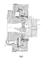
- the second embodiment of the clamping device shown in Fig. 2 is for extrusion nozzles designed with uniform external dimensions.
- the second embodiment differs from the first embodiment in particular by the formation of the tool-side connection area 7.
- This Tool-side connection region 7 comprises according to the second embodiment hook-shaped end portion 15 which engages over the extrusion tool 1.
- the extruder-side terminal portion 6 of the clamping ring 8a differs from the connection portion 6 of the clamping ring 8 of FIG. 1, characterized in that the support surface of the 11th 1 by a provided on the first nozzle plate in the extrusion direction support surface 48 is replaced.
- the initiation of the clamping force therefore takes place in the second embodiment on the hook-shaped end portions 15 of the clamping ring 8a in the extrusion die 1, the is supported by the support surface 48 on the extruder 3.
- the third embodiment of the clamping device shown in Fig. 3 has a clamping ring 8b with a tool-side connection region 7, which is substantially cylindrical is formed and has a thread 14.
- This thread 14 is present as Formed internal thread into which a corresponding external thread of a not shown, in the extrusion direction first nozzle plate can be screwed.
- Also in this embodiment is the integrally formed with the clamping ring 8 bearing surface 11 by a replaced in the extrusion direction first nozzle plate support surface 48 replaced.
- the piston 31 is designed as an annular piston which surrounds the clamping ring 8 concentrically.
- the piston 31st a single supply line 44 is assigned for the application of the clamping pressure, wherein Also several leads are possible.
- three release pistons 42 are provided, which are also the position of the associated Mark tensioning hook 18.
- the release cylinder 42 are each connected to a supply line 43 for the Provided with a release pressure.
- Fig. 5 shows a plan view of a clamping ring 8b with thread 14 according to the third embodiment.
- the two radial grooves 12 are particularly good detect.
- Figures 7 and 8 show the clamping ring 8 according to the first embodiment, wherein Again, the formation of the radial grooves 12 is shown. Further in Figs. 7 and 8 to see the support surface 11, which limits an annular collar 52 in the axial direction. In FIGS. 7 and 8, no details regarding the shape of the melt channels are shown.
Landscapes
- Engineering & Computer Science (AREA)
- Mechanical Engineering (AREA)
- Extrusion Moulding Of Plastics Or The Like (AREA)
Applications Claiming Priority (2)
| Application Number | Priority Date | Filing Date | Title |
|---|---|---|---|
| DE102004009354A DE102004009354B4 (de) | 2004-02-26 | 2004-02-26 | Spannvorrichtung |
| DE102004009354 | 2004-02-26 |
Publications (2)
| Publication Number | Publication Date |
|---|---|
| EP1568464A2 true EP1568464A2 (fr) | 2005-08-31 |
| EP1568464A3 EP1568464A3 (fr) | 2005-10-26 |
Family
ID=34745284
Family Applications (1)
| Application Number | Title | Priority Date | Filing Date |
|---|---|---|---|
| EP05003962A Withdrawn EP1568464A3 (fr) | 2004-02-26 | 2005-02-24 | Dispositife de serrage pour buse d'extrusion et une extrudeuse utilise le meme |
Country Status (2)
| Country | Link |
|---|---|
| EP (1) | EP1568464A3 (fr) |
| DE (1) | DE102004009354B4 (fr) |
Cited By (1)
| Publication number | Priority date | Publication date | Assignee | Title |
|---|---|---|---|---|
| CN109177111A (zh) * | 2018-07-03 | 2019-01-11 | 柳州通亿汽车配件制造有限公司 | 一种便于更换的塑胶挤出模具 |
Family Cites Families (6)
| Publication number | Priority date | Publication date | Assignee | Title |
|---|---|---|---|---|
| DE1942724U (de) * | 1966-05-07 | 1966-07-21 | Rheinstahl Henschel Ag | Vorrichtung zum zentrieren von rohrduesen an extrudern fuer kunststoffverarbeitung. |
| US4124346A (en) * | 1976-04-07 | 1978-11-07 | The Goodyear Tire & Rubber Company | Extruder die arrangement |
| DE2707351C3 (de) * | 1977-02-19 | 1980-08-28 | Hermann Berstorff Maschinenbau Gmbh, 3000 Hannover | Sicherheitsvorrichtung für Extrudergehäuse und Siebvorrichtung |
| DE3712343A1 (de) * | 1987-04-11 | 1988-10-20 | Krupp Gmbh | Extrusionskopf mit einer klemmeinrichtung fuer die werkzeugteile |
| AT3318U1 (de) * | 1998-09-29 | 2000-01-25 | Technoplast Kunststofftechnik | Vorrichtung zum extrudieren von kunststoffrohren oder profilen |
| AT413270B (de) * | 2001-08-14 | 2006-01-15 | Greiner Extrusionstechnik Gmbh | Haltevorrichtung für eine extrusionsdüse |
-
2004
- 2004-02-26 DE DE102004009354A patent/DE102004009354B4/de not_active Expired - Fee Related
-
2005
- 2005-02-24 EP EP05003962A patent/EP1568464A3/fr not_active Withdrawn
Cited By (1)
| Publication number | Priority date | Publication date | Assignee | Title |
|---|---|---|---|---|
| CN109177111A (zh) * | 2018-07-03 | 2019-01-11 | 柳州通亿汽车配件制造有限公司 | 一种便于更换的塑胶挤出模具 |
Also Published As
| Publication number | Publication date |
|---|---|
| DE102004009354A1 (de) | 2005-09-15 |
| DE102004009354B4 (de) | 2006-07-27 |
| EP1568464A3 (fr) | 2005-10-26 |
Similar Documents
| Publication | Publication Date | Title |
|---|---|---|
| DE10121540B4 (de) | Geteilte mechanische Flächendichtung | |
| EP2427317B1 (fr) | Buse chaude d'injection latérale | |
| EP2849918B1 (fr) | Distributeur de fluide de refroidissement pour machine-outil | |
| DE69504330T2 (de) | Abstandeinstellung von einem strömungskanal in einer vorrichtung zum formen von kunststoffteilen | |
| DE202014010742U1 (de) | Schneidnaben-Zapfenantriebsmechanismus und Schnelltrenn-Nabe für einen Unterfluid-Granulator | |
| EP2303539A2 (fr) | Buse d'injection pour moule d'injection | |
| DE102017108576B4 (de) | Plattenschieber, Fixierelement und Verfahren zur Montage eines Plattenschiebers | |
| DE69718559T2 (de) | Vier beheizte Düseverteiler miteinander verbunden in einer gemeinsamen Fläche | |
| EP2086740A1 (fr) | Dispositif pour fermer des tronçons de canaux dans un répartiteur à canaux chauds ou à canaux froids | |
| DE102009035289B4 (de) | Formwerkzeugadapterplatte, Formwerkzeughalteglied und damit assoziierte Formklemmvorrichtung | |
| DE2644670C2 (de) | Nadelventil für Kunststoff-Spritzgießwerkzeuge | |
| DE2166908B2 (de) | Kunststoffwarmverformungsmaschine zum Tiefziehen von einseitig offenen Hohlkörpern | |
| AT413270B (de) | Haltevorrichtung für eine extrusionsdüse | |
| DE1804640C2 (de) | Spritzkopf zur Herstellung von Kunststoffrohren oder -schläuchen | |
| DE102004009354B4 (de) | Spannvorrichtung | |
| EP2375088A2 (fr) | Dispositif de fixation pour la liaison de force de deux pièces usinées et utilisation d'un dispositif de fixation | |
| EP2561260B1 (fr) | Dispositif d'assemblage de tuyaux | |
| DE102009054385A1 (de) | Kupplungsvorrichtung und damit ausgestattete Streckblasvorrichtung | |
| DE102018123145A1 (de) | Leichtbauhonwerkzeug und Honleiste | |
| WO2003029534A1 (fr) | Filiere | |
| DE2110379A1 (de) | Spannfutter | |
| DE102007043386B4 (de) | Kokille zum Stranggießen von Metall und Verfahren zum Herstellen einer derartigen Kokille | |
| DE102020100444A1 (de) | Kupplungselement | |
| DE102022109427B4 (de) | Radialpresse | |
| EP1920901B1 (fr) | Dispositif destiné à la fixation de matrices |
Legal Events
| Date | Code | Title | Description |
|---|---|---|---|
| PUAI | Public reference made under article 153(3) epc to a published international application that has entered the european phase |
Free format text: ORIGINAL CODE: 0009012 |
|
| AK | Designated contracting states |
Kind code of ref document: A2 Designated state(s): AT BE BG CH CY CZ DE DK EE ES FI FR GB GR HU IE IS IT LI LT LU MC NL PL PT RO SE SI SK TR |
|
| AX | Request for extension of the european patent |
Extension state: AL BA HR LV MK YU |
|
| PUAL | Search report despatched |
Free format text: ORIGINAL CODE: 0009013 |
|
| AK | Designated contracting states |
Kind code of ref document: A3 Designated state(s): AT BE BG CH CY CZ DE DK EE ES FI FR GB GR HU IE IS IT LI LT LU MC NL PL PT RO SE SI SK TR |
|
| AX | Request for extension of the european patent |
Extension state: AL BA HR LV MK YU |
|
| AKX | Designation fees paid | ||
| STAA | Information on the status of an ep patent application or granted ep patent |
Free format text: STATUS: THE APPLICATION IS DEEMED TO BE WITHDRAWN |
|
| 18D | Application deemed to be withdrawn |
Effective date: 20060427 |
|
| REG | Reference to a national code |
Ref country code: DE Ref legal event code: 8566 |