EP1568464A2 - Clamping device for extrusion mould and extruder with such a device - Google Patents
Clamping device for extrusion mould and extruder with such a device Download PDFInfo
- Publication number
- EP1568464A2 EP1568464A2 EP05003962A EP05003962A EP1568464A2 EP 1568464 A2 EP1568464 A2 EP 1568464A2 EP 05003962 A EP05003962 A EP 05003962A EP 05003962 A EP05003962 A EP 05003962A EP 1568464 A2 EP1568464 A2 EP 1568464A2
- Authority
- EP
- European Patent Office
- Prior art keywords
- clamping
- extruder
- tool
- clamping device
- ring
- Prior art date
- Legal status (The legal status is an assumption and is not a legal conclusion. Google has not performed a legal analysis and makes no representation as to the accuracy of the status listed.)
- Withdrawn
Links
- 238000001125 extrusion Methods 0.000 title claims abstract description 96
- 230000003247 decreasing effect Effects 0.000 claims 1
- 238000004519 manufacturing process Methods 0.000 description 8
- 239000000155 melt Substances 0.000 description 7
- 238000007789 sealing Methods 0.000 description 7
- 238000000034 method Methods 0.000 description 5
- 230000015572 biosynthetic process Effects 0.000 description 3
- 230000000295 complement effect Effects 0.000 description 2
- 238000010438 heat treatment Methods 0.000 description 2
- 230000000977 initiatory effect Effects 0.000 description 2
- 239000002861 polymer material Substances 0.000 description 2
- 230000005540 biological transmission Effects 0.000 description 1
- 238000004140 cleaning Methods 0.000 description 1
- 230000003750 conditioning effect Effects 0.000 description 1
- 238000001816 cooling Methods 0.000 description 1
- 230000000694 effects Effects 0.000 description 1
- 238000004049 embossing Methods 0.000 description 1
- 210000003746 feather Anatomy 0.000 description 1
- 230000003993 interaction Effects 0.000 description 1
- 230000007257 malfunction Effects 0.000 description 1
- 239000000463 material Substances 0.000 description 1
- 230000002093 peripheral effect Effects 0.000 description 1
- 238000002360 preparation method Methods 0.000 description 1
- 238000007639 printing Methods 0.000 description 1
- 238000003860 storage Methods 0.000 description 1
- 238000011144 upstream manufacturing Methods 0.000 description 1
Images



Classifications
-
- B—PERFORMING OPERATIONS; TRANSPORTING
- B29—WORKING OF PLASTICS; WORKING OF SUBSTANCES IN A PLASTIC STATE IN GENERAL
- B29C—SHAPING OR JOINING OF PLASTICS; SHAPING OF MATERIAL IN A PLASTIC STATE, NOT OTHERWISE PROVIDED FOR; AFTER-TREATMENT OF THE SHAPED PRODUCTS, e.g. REPAIRING
- B29C48/00—Extrusion moulding, i.e. expressing the moulding material through a die or nozzle which imparts the desired form; Apparatus therefor
- B29C48/25—Component parts, details or accessories; Auxiliary operations
- B29C48/256—Exchangeable extruder parts
- B29C48/2562—Mounting or handling of the die
-
- B—PERFORMING OPERATIONS; TRANSPORTING
- B29—WORKING OF PLASTICS; WORKING OF SUBSTANCES IN A PLASTIC STATE IN GENERAL
- B29C—SHAPING OR JOINING OF PLASTICS; SHAPING OF MATERIAL IN A PLASTIC STATE, NOT OTHERWISE PROVIDED FOR; AFTER-TREATMENT OF THE SHAPED PRODUCTS, e.g. REPAIRING
- B29C48/00—Extrusion moulding, i.e. expressing the moulding material through a die or nozzle which imparts the desired form; Apparatus therefor
- B29C48/03—Extrusion moulding, i.e. expressing the moulding material through a die or nozzle which imparts the desired form; Apparatus therefor characterised by the shape of the extruded material at extrusion
-
- B—PERFORMING OPERATIONS; TRANSPORTING
- B29—WORKING OF PLASTICS; WORKING OF SUBSTANCES IN A PLASTIC STATE IN GENERAL
- B29C—SHAPING OR JOINING OF PLASTICS; SHAPING OF MATERIAL IN A PLASTIC STATE, NOT OTHERWISE PROVIDED FOR; AFTER-TREATMENT OF THE SHAPED PRODUCTS, e.g. REPAIRING
- B29C48/00—Extrusion moulding, i.e. expressing the moulding material through a die or nozzle which imparts the desired form; Apparatus therefor
- B29C48/03—Extrusion moulding, i.e. expressing the moulding material through a die or nozzle which imparts the desired form; Apparatus therefor characterised by the shape of the extruded material at extrusion
- B29C48/12—Articles with an irregular circumference when viewed in cross-section, e.g. window profiles
Definitions
- the invention relates to a clamping device for an extrusion tool the features of the preamble of claim 1 and to a clamping device for an extrusion tool having the features of the preamble of claim 19.
- Clamping devices of this type are known from DE 102 35 151 A1.
- the invention further relates to an extruder with such a clamping device.
- Extrusion tools give plastic polymer material the desired spatial form the profiles to be produced. Parts of the tools, namely the nozzles, are on the extruder clamped. Here are - apart from a few special technical solutions - each individual nozzles needed for each produced spatial shape of the profiles.
- the clamped tool in a Setup process are disconnected from the extruder to feed it for cleaning.
- the next production order is then carried out with another nozzle, the first clamped on the extruder, brought to operating temperature, must be aligned, and then tightened.
- the production time can be with a tool be very short in some cases, so that the comparatively significant time required for the Hinst processes the manufacturing costs increased. This particularly affects the production of Profiles that are produced in small batches, the setup costs are considerable can accept.
- the high time requirement comes in particular because the nozzle on the extruder head means several screws extremely firmly using torque wrenches attached must be in order to withstand the pressures prevailing in the extrusion and the Close the output of the extruder cylinder tight. It must be before tightening a Heating the devices to operating temperature done to thermal expansion the interconnected components, so that in operation a specified clamping force is maintained. The tightening of the screws takes place under Attention to certain processes. Failure to follow these procedures may result in malfunctions In addition, operation or damage to the extruder may cause clamping errors occur.
- the nozzle must be downstream in terms of the extrusion process Work steps, such as calibration, cooling, embossing, printing, lengthening, etc. exactly by means such as e.g. Spirit levels, rotationally aligned, what also requires a certain amount of time and represents a possible source of error.
- Work steps such as calibration, cooling, embossing, printing, lengthening, etc. exactly by means such as e.g. Spirit levels, rotationally aligned, what also requires a certain amount of time and represents a possible source of error.
- the screw can not be solved quickly enough, if In the extruder, an overpressure builds up to decouple the nozzle for protection.
- the aforementioned DE 102 35 151 A1 discloses a holding device for an extrusion die, consisting of several in the extrusion direction successively arranged nozzle plates is formed.
- the clamping of this extrusion die is effected by two plate-shaped Tension elements, which are arranged on the sides of the extrusion die.
- the one end of this Tensile elements is the last in the extrusion direction nozzle plate, which is the tool exit forms, connected.
- the other end of the tension elements is a movable cylinder connected to a piston-cylinder arrangement.
- the plate package is between the with screwed to the extruder, fixed piston of the piston-cylinder assembly and the clamped tool exit end of the tension elements.
- the piston-cylinder assembly For clamping the extrusion nozzle the piston-cylinder assembly is subjected to a clamping pressure, the movable cylinder and connected to this pulling element against the extruder urges and thereby the tension element with a tensile force acting in the direction of the extruder applied. This will be the between the tool exit end of the tension elements and the fixed piston of the piston-cylinder assembly clamped nozzle pack pressed against the piston and thus clamped on the extruder.
- This known device has the disadvantage that the outer dimensions of the nozzle of the holding device are determined. This device is therefore not for different nozzles usable, but requires uniform nozzle external dimensions. Moreover, you can Nozzles with large profile cross sections or z. B. Distributor flanges for double-strand production due to the limited nozzle external dimensions can not be clamped with this system.
- Another problem of the known devices for mounting extrusion nozzles is that the flow behavior of the melt in the device for clamping can be affected.
- the invention is therefore based on the object, a clamping device of the above mentioned type to improve such that a flexible use of the clamping device for various extrusion tools and makes the tool change easier becomes.
- the invention is also based on the object, an extruder with such Specify clamping device.
- Another object of the invention is the flow behavior in the tensioning device to improve.
- the invention has the advantage that between the extrusion die and the extruder the clamping means is arranged, on which the clamping element acts, so that the clamping force is introduced into the clamping ring.
- the extrusion tool is thus on the intermediate Clamping device clamped on the extruder.
- the clamping device according to the invention is therefore flexible usable, since different Extrusion tools with the tool-side connection area of the clamping device easy can be connected.
- the extruder-side first nozzle plate can be equipped with a suitable connection are, by which this plate with the clamping means releasably or firmly connected becomes.
- the downstream remaining nozzle plates can be mounted as before.
- clamping means also the immediate introduction of the clamping force of Uncoupled extrusion tool, creating a greater creative freedom because the conception of the tool does not have any restrictions on the introduction subject to the clamping force.
- the invention also has the advantage that the clamping means and the associated Extrusion tool is quickly removed by loosening the clamping element of the extruder, so that the extrusion tool can be safely protected from damage due to overpressure can.
- the clamping and releasing of the clamping means by the clamping element takes place simple way without effort, so that the relevant components, in particular the Extrusion tool, not to be damaged.
- the set-up times for the tool change are greatly shortened by means of the invention.
- a nozzle change is in one Period of about 1 min to accomplish, as far as no material change on the machine is to be made.
- the clamping means comprises a clamping ring with a radially projecting shoulder disposed in the extruder-side connection area and with a pointing to the extrusion tool first contact surface is formed.
- the advantage the formation of the clamping means as a clamping ring is that the clamping ring particularly can be easily coupled to the tool-side end of the extruder.
- To the clamping ring comprises a radially projecting shoulder, which in the extruder-side connection area the clamping ring is arranged and pointing with an extrusion tool first contact surface is formed. At this aligned first contact surface can attack the clamping element and pull the clamping ring against the extruder.
- the extruder-side connection region of the clamping ring on an axial extension in which at least one in the direction of the extruder open radial groove is provided for aligning the clamping ring.
- the radial groove In a further preferred embodiment of the invention, the extruder-side connection region the clamping ring provided for in the circumferential direction bearing surface, with respect to the first contact surface at least partially in opposite Direction is arranged. By this arrangement at least a portion of the support surface a sealing surface is created, which is against an associated sealing surface of the extruder is pressed when the first contact surface of the clamping ring applied with a clamping force becomes.
- This embodiment of the invention provides a particularly simple and effective Type of sealing of the clamping ring against the clamping ring flowing through Melt.
- the tool-side connection region can be made in one piece with an extruder-side Be formed end portion of the extrusion die.
- This embodiment is particularly suitable for clamping of extrusion nozzles, the a plurality of nozzle plates are formed, wherein the tool-side connection area with the in the extrusion direction of the first nozzle plate is integrally connected.
- the tool-side connection region can be substantially cylindrical and have a thread.
- This embodiment of the invention is particularly flexible and allows the connection of the clamping device to a wide variety of extrusion tools.
- the clamping device in such a way that the tool-side connection area a hook-shaped end portion comprising the extrusion die overlaps.
- This embodiment of the invention is for extrusion nozzles with uniform external dimensions provided or for extrusion nozzles, which are used for the production of larger series and only be changed after longer production times.
- the clamping element is associated with a release element, which is a Actuating force for generating a substantially radial release movement of the clamping element applies.
- a release element which is a Actuating force for generating a substantially radial release movement of the clamping element applies.
- the clamping element may be associated with a closing element, which has a force for generating a substantially radial / axial closing movement of the clamping element applies.
- the actuating force acts to produce the closing movement the force to generate the release movement against. This allows the force be used to generate the closing movement to bias the release element.
- the tensioning element comprises at least two tension hooks.
- the clamping hook With the help of the clamping hook, the clamping means, in particular the clamping ring, particularly easily and quickly coupled to the extruder or of decoupled from this.
- the tensioning hooks can each have a recess with an extruder-side second contact surface have, with the provided on the clamping ring first contact surface in plant can be brought.
- the clamping force in the clamping ring be initiated.
- This embodiment of the invention allows a particularly simple introduction the clamping force in the clamping ring.
- the clamping hooks each have a projection with a tool side third contact surface, which cooperates with the actuating device.
- the tool-side arrangement of the third contact surface in the direction of the extrusion tool points, an attack point is created at which the actuator attaches to apply an acting in the extruder direction clamping force on the clamping hook.
- the release element comprises a spring ring, on whose circumference the Clamping hooks are arranged non-positively.
- This spring ring surrounds the clamping hooks and brings a radially acting force on the clamping hook, which is a substantially radial Release movement of the clamping hook causes.
- This embodiment of the invention has the advantage that by means of a single component, namely the spring ring, all clamping hooks can be operated.
- the closing element comprises a radially arranged nose formed on each tensioning hook, wherein the nose an inclined, extruder-side surface having, over a stationary edge of a guide member is movable.
- the tension hooks can each have an inner side facing the tensioning ring and one opposite having arranged outside, wherein the recess and the projection on the Inside, as well as the nose and a spring ring receiving groove on the outside are formed, and the projection between the groove and the nose arranged and as Fulcrum is formed.
- the tensioning hook is movable as a lever, wherein the projection as Pivot acts.
- the actuating forces are determined by the spring ring arranged in the groove or introduced via the radially arranged nose and cause a release movement or a closing movement of the clamping hook. This is the removal or the clamping facilitates the extrusion tool.
- the actuating device comprises a for tensioning the clamping hooks in the axial direction of the clamping device movable piston, the means for supporting the Has clamping hook, wherein a projection with an extruder-side fourth contact surface is provided, with the provided on the clamping hooks each third contact surface can be brought into contact.
- This embodiment of the actuator allows for easy How to tighten and loosen the tension hooks. These include the means for storage the clamping hook a projection with an extruder-side fourth contact surface.
- This fourth contact surface thus points in the direction of the extruder and allows the transmission a force acting in the extruder clamping force on the tool-side third contact surface on the tension hook.
- a ring insert may be provided, which is the clamping ring coaxially in the extrusion direction arranged upstream and the inner diameter in the extrusion direction constant or variable. This means that the inside diameter can be constant or in the extrusion direction can get bigger or smaller.
- this ring insert is the Adjusted diameter of the leading to the extrusion die melt channel, whereby the Flow behavior of the melt is positively influenced.
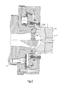
- Fig. 1 is a tensioning device according to a first embodiment of the invention with their most important components, as used in the polymer material extrusion for Use comes. Further, in Fig. 1, the end of an extruder 3 and a broken represented Extrusion die 1 shown, which consists of several together screwed nozzle plates consists. The tensioning device is between the extruder 3 and the extrusion die 1, in particular arranged in the extrusion direction of the first nozzle plate of the extrusion die 1.
- the tensioning device has a tensioning element 2, which in the first shown in FIG Embodiment is designed as a clamping hook 18. To a symmetrical force application to effect, at least two clamping hooks 18 are required. Usually used three clamping hooks 18, which are arranged offset on a circular circumference by 120 ° are. A larger number of tension hooks is also possible.
- an actuating device 4 which cooperates with the clamping hooks 18, to move them in the axial direction of the clamping device.
- the tension hook 18 is associated with a clamping means 5, which in the present case is designed as a clamping ring 8.
- the Clamping hooks 18 are brought into engagement with the clamping ring 8 and act upon this with a force acting in the direction of the extruder 3 clamping force, so that with the clamping ring 8 connected extrusion tool 1 is clamped on the extruder 3.
- the clamping position is illustrated by the upper clamping hook 18 shown in FIG.
- the release position, in which the clamping hook 18 releases the clamping ring 8, is based on the in 1 lower tensioning hook 18 shown.
- the clamping ring 8 has an extruder-side connection region 6 and a tool side Connection area 7 on.
- the extruder-side connection region 6 in this case comprises the part the clamping ring 8, which faces the extruder.
- the tool-side connection area Figure 7 comprises the part of the clamping ring 8 which faces the extrusion die.
- the extruder-side connecting portion 6 has a radially projecting shoulder 9, the is formed with a pointing to the extrusion tool first contact surface 10.
- the Paragraph 9 may be formed as the clamping ring encircling collar.
- a support surface 11 is provided at the extruder-side end of the clamping ring 8, at least partially opposite to the first contact surface 10 of the clamping ring 8, is arranged in particular in parallel.
- the relevant section of the bearing surface 11 lies on an insert, in particular one Perforated plate 35 and a ring 36, and is characterized by the extruder 3 frictionally connected.
- About the first contact surface 10 and arranged opposite to this Support surface 11 is introduced through the clamping hooks 18 in the clamping ring 8 Transferred clamping force to the extruder 3.
- the support surface 11 forms a sealing surface, which seals the clamping device against the melt.
- the support surface 11 is radially inwardly by a peripheral edge of the clamping ring 8 and bounded radially outwardly by a concentric annular groove 37.
- the radially outer Wall of the annular groove 37 is formed as an axial annular extension 37 a, which extends in the direction of the extruder 3 tapers.
- this annular extension 37a are two opposite arranged radial grooves 12 provided, which serves to align the clamping ring 8. A larger or smaller number of radial grooves 12 is possible.
- the extruder-side connection region 6 of the clamping ring 8 engages over a complementary to Ring groove 37 formed inner part 38 of a heated base plate 39, with the extruder 3 is screwed. Between the inner part 38 and the annular groove 37, a gap is provided, which allows the biasing of the clamping ring 8.
- a feather key which engages in the radial groove 12 for aligning the clamping ring 8, with the inner part 38 of the base plate 39 screwed by a screw 40.
- connection of the clamping ring 8 with the extruder 3 is thus essentially about the acting as a sealing surface bearing surface 11 and the contact surface 10 on the clamping ring 8 introduced clamping force.
- the simple, fast and safe alignment of the clamping ring 8 is through the radial groove 12 and screwed to the base plate 39 key causes.
- the tool-side terminal portion 7 is in the present first embodiment according to Fig. 1 in one piece with an extruder-side end portion 13 of the extrusion die 1, wherein the end portion 13 part of a first nozzle plate in the extrusion direction of the extrusion die, in particular the extrusion die.
- the clamping hooks 18 cooperating with the clamping ring 8 are each constructed as follows:
- Each tension hook 18 comprises an elongated body which is substantially in axial Direction of the tensioning device is arranged. On the inside, which is arranged radially inside 28 of the clamping hook 18 is in the region of the tool-side end of the clamping hook 18, a recess 19 is provided, which is complementary to the projection 9 on the clamping ring. 8 is trained.
- the recess 19 has a second contact surface 20, the extruder side, So is arranged pointing to the extruder 3.
- the definition of the orientation of a surface as an extruder side or on the tool side is generally to be understood that the normal to this area in the direction of the extruder (on the extruder side) or in the direction of the tool (on the tool side) runs.
- the second contact surface 20 on the clamping hook 18 is in clamping position on the first bearing surface 10 on the clamping ring 8, as shown by the upper clamping hook 18 in Fig. 1.
- the extruder-side end of the tensioning hook 18 has a projection 21 with a tool-side third contact surface 22 on.
- the actuator 4 engages behind this projection 21, so that the third contact surface 22 on the clamping hook 18 with an acting in the extruder direction Clamping force can be applied and pulled in the direction of the extruder 3.
- the release and tensioning of the clamping hook 18 is a release element 16 and a Closing member 17 supports the radial pivoting movement of the clamping hook 18th to the clamping ring 8 out or from the clamping ring 8 away.
- the clamping hook is pivoted away in the release position from the clamping ring 8, so that the paragraph 9 of the clamping ring 8 of the recess 19 of the clamping hook 18 is released.
- the clamping ring 8 can thus easily removed from the extruder 3 become.
- the pivoting movement of the clamping hook for carrying out the radial release movement or closing movement takes place about one along the projection 21 of the clamping hook 18th extending pivot axis.
- the projection 21 thus serves both as an attack surface for the Initiation of the clamping force by the actuator 4 and on the other hand as a fulcrum for the pivoting movement of the clamping hook 18th
- the release element 16 comprises a spring ring 23 which is in a groove 30 on the outside 29 of the clamping hook 18 is added.
- the closing element 17 comprises a radially arranged nose 24, which on the outer side 29 each clamping hook 18 is formed.
- the nose 24 has an oblique, extruder-side surface 25 on. This means that the surface 25 is opposite to a direction perpendicular to the extrusion direction standing inclined surface, wherein the distance of the surface 25 to the extruder. 3 increases to the outside.
- the nose 24 is tapered outward Projection formed on the tool-side end of the clamping hook 18 in the radial Extension is provided.
- the inclined surface 25 is associated with a fixed edge 26 of a guide member 27 such that the surface 25 is movable over this stationary edge 26.
- the guide member 27 is as a circumferential collar of a cover plate 41 screwed to the base plate 39 is formed, wherein the fixed edge 26 of the tool-side inner edge of the cover plate 41st equivalent.
- the radial closing movement is based on the basis of the lower Clamping hook 18 shown thereby generating that the lower clamping hook 18th is pulled by the actuator 4 in the direction of the extruder 3. It works the surface 25 of the nose 24 on the stationary edge 26 and causes due to their inclination a radial movement of the clamping hook 18 in the direction of the clamping ring. 8
- the nose 24 In the clamping position shown by the upper clamping hook 18, the nose 24 is located the inside of the guide member 27, whereby the clamping hook 18 in the clamping position is locked.
- the spacing of the nose 24 from the projection 21 of the clamping hook is a moment about the along the projection 21 extending pivot axis of the Spannhakens generated 18, which pivoting the clamping hook 18 and thus the Closing movement causes.
- the actuator 4 is constructed as follows:
- the actuating device 4 comprises a movable in the axial direction of the clamping device Piston 31 which is guided in a cylinder formed in the cover plate 41.
- the cylinder is provided with a supply line 44 for supplying a pressurized medium for application of the piston 31 equipped with a clamping pressure.
- the piston 31 is also provided with a another dissolving piston 42 in Appendix, the movable in the base plate 39 in the axial direction is stored.
- the release piston 42 is provided via a base plate 39 in the Supply line 43 can be acted upon by a release pressure.
- the piston 31 and the release piston 42 is sealed by sealing rings 49, 50, 51.
- the piston 31 is in two parts with a radially inwardly disposed inner part 45 and a Outer part 47 is formed, as seen in Fig. 1.
- a receiving space 46 for Receiving the tool-side end of the clamping hook 18 is formed, the three substantially having mutually perpendicular walls, wherein the receiving space 46 is opened in the direction of the extrusion tool 1. Through this opening is the Cocking hook 18 out.
- the inner part 45 is formed in cross-section L-shaped, wherein the two legs of the Inner part 45 form two walls of the receiving space 46.
- the third wall of the reception room 46 is formed by the outer part 47. It is perpendicular to the extrusion direction arranged legs of the inner part 45 with the outer part 47 z. B. screwed.
- the parallel to the extrusion direction and the outer part 47 arranged leg of the inner part 45 is provided at its tool-side end with a projection 32.
- the Projection 32 has an extruder-side fourth contact surface 33, which with the at Clamping hooks 18 respectively provided third contact surface 22 can be brought into abutment. Of the Projection 32 on the piston 31 thus engages behind the projection provided on the clamping hook 18 21, so that acting in the direction of the extruder clamping force of the piston 31 on the clamping hook 18 can be transferred.
- the receiving space 46 is slightly larger than the extruder-side end of the clamping hook 18, whereby a limited pivotal movement of the clamping hook 18 is made possible.
- a particularly good flow behavior of the melt when flowing through the clamping device is achieved by a ring insert 34 between the extruder 3 and the extrusion die 1 is arranged and in this area at least partially the melt channel forms.
- the inner diameter of the ring insert 34 is variable and increases in the extrusion direction, d. h.,
- the inner diameter of the ring insert 34 is the Extrusion tool 1 towards larger.
- the inner diameter corresponds to the extruder side of the ring insert 34 the outlet diameter of the extruder 3.
- the inner diameter on the tool side of the ring insert 34 corresponds to the inlet diameter of the extrusion die 1, wherein in the example shown here, the inlet diameter of the extrusion die 1 is greater than the outlet diameter of the extruder 3.
- Another diameter constellation in which, for example, the inlet diameter of Extrusion tool 1 is smaller than the outlet diameter of the extruder 3, is also conceivable.
- the inner diameter of the ring insert 34 increases in the extrusion direction off, d. that is, the inner diameter becomes smaller toward the extrusion die 1. at same outlet diameter of the extruder 3 and inlet diameter of the extrusion die 1, the inner diameter of the ring insert 34 is constant and corresponds to the Outlet or inlet diameter.
- the sleeve 36 or another insert for example, a perforated plate 35, arranged.
- the ring insert 34 improves the flow behavior of the melt.
- the above-described ring insert 34 is preferably in a clamping device used, which has a clamping ring 8, as shown in Fig. 1.
- clamping hooks engage behind the clamping ring provided on the radial 20 paragraph 9 above and are by the investment of the nose 24 on the inside of the cover plate 41 locked.
- clamping pressure are the Clamping hook 18 and the standing with these engaged clamping ring 8 with a in the direction the extruder 3 acted upon clamping force, so that connected to the clamping ring 8 Extrusion tool 1 is securely clamped on the extruder 3.
- the release piston 42 is subjected to a release pressure, the piston 31 and the pivotally mounted therein clamping hooks 18 in Direction of the extrusion tool 1 moves.
- the spring ring 23 By the radially inward acting force the spring ring 23, the clamping hooks 18 are pivoted outwards, so that the radially extending paragraph 9 of the clamping ring 8 comes free.
- the piston movement takes place in such a way that the tool-side end of the parallel to Extrusion direction arranged leg of the inner part 45 of the piston 31 against the Paragraph 9 urges and thus facilitates the removal of the clamping ring 8.
- the second embodiment of the clamping device shown in Fig. 2 is for extrusion nozzles designed with uniform external dimensions.
- the second embodiment differs from the first embodiment in particular by the formation of the tool-side connection area 7.
- This Tool-side connection region 7 comprises according to the second embodiment hook-shaped end portion 15 which engages over the extrusion tool 1.
- the extruder-side terminal portion 6 of the clamping ring 8a differs from the connection portion 6 of the clamping ring 8 of FIG. 1, characterized in that the support surface of the 11th 1 by a provided on the first nozzle plate in the extrusion direction support surface 48 is replaced.
- the initiation of the clamping force therefore takes place in the second embodiment on the hook-shaped end portions 15 of the clamping ring 8a in the extrusion die 1, the is supported by the support surface 48 on the extruder 3.
- the third embodiment of the clamping device shown in Fig. 3 has a clamping ring 8b with a tool-side connection region 7, which is substantially cylindrical is formed and has a thread 14.
- This thread 14 is present as Formed internal thread into which a corresponding external thread of a not shown, in the extrusion direction first nozzle plate can be screwed.
- Also in this embodiment is the integrally formed with the clamping ring 8 bearing surface 11 by a replaced in the extrusion direction first nozzle plate support surface 48 replaced.
- the piston 31 is designed as an annular piston which surrounds the clamping ring 8 concentrically.
- the piston 31st a single supply line 44 is assigned for the application of the clamping pressure, wherein Also several leads are possible.
- three release pistons 42 are provided, which are also the position of the associated Mark tensioning hook 18.
- the release cylinder 42 are each connected to a supply line 43 for the Provided with a release pressure.
- Fig. 5 shows a plan view of a clamping ring 8b with thread 14 according to the third embodiment.
- the two radial grooves 12 are particularly good detect.
- Figures 7 and 8 show the clamping ring 8 according to the first embodiment, wherein Again, the formation of the radial grooves 12 is shown. Further in Figs. 7 and 8 to see the support surface 11, which limits an annular collar 52 in the axial direction. In FIGS. 7 and 8, no details regarding the shape of the melt channels are shown.
Landscapes
- Engineering & Computer Science (AREA)
- Mechanical Engineering (AREA)
- Extrusion Moulding Of Plastics Or The Like (AREA)
Abstract
Die Erfindung betrifft eine Spannvorrichtung für ein Extrusionswerkzeug mit einem Spannelement zum lösbaren Verbinden des Extrusionswerkzeuges mit einem Extruder und einer Betätigungseinrichtung zum Lösen und Spannen des Spannelements. Die Spannvorrichtung zeichnet sich durch ein Spannmittel aus mit einem extruderseitigen Anschlussbereich, der durch das Spannelement mit dem Extruder lösbar verbunden ist, und einem werkzeugseitigen Anschlussbereich der mit dem Extrusionswerkzeug lösbar oder fest verbunden ist.The invention relates to a clamping device for an extrusion tool with a clamping element for detachably connecting the extrusion die to an extruder and a Actuating device for releasing and tensioning the clamping element. The tensioning device characterized by a clamping means with an extruder-side connection area, which is releasably connected by the clamping element with the extruder, and a tool side Connection area which is releasably or firmly connected to the extrusion tool.
Description
Die Erfindung bezieht sich auf eine Spannvorrichtung für ein Extrusionswerkzeug mit den Merkmalen des Oberbegriffs des Anspruchs 1 und auf eine Spannvorrichtung für ein Extrusionswerkzeug mit den Merkmalen des Oberbegriffs des Anspruchs 19. Spannvorrichtungen dieser Gattung sind aus der DE 102 35 151 A1 bekannt. Die Erfindung bezieht sich ferner auf einen Extruder mit einer derartigen Spannvorrichtung.The invention relates to a clamping device for an extrusion tool the features of the preamble of claim 1 and to a clamping device for an extrusion tool having the features of the preamble of claim 19. Clamping devices of this type are known from DE 102 35 151 A1. The invention further relates to an extruder with such a clamping device.
Extrusionswerkzeuge geben plastischem Polymermaterial die gewünschte Raumform für die herzustellenden Profile. Teile der Werkzeuge, nämlich die Düsen, werden am Extruder aufgespannt. Dabei werden ― abgesehen von wenigen technischen Sonderlösungen ― jeweils individuelle Düsen für eine jede herzustellende Raumform der Profile benötigt.Extrusion tools give plastic polymer material the desired spatial form the profiles to be produced. Parts of the tools, namely the nozzles, are on the extruder clamped. Here are - apart from a few special technical solutions - each individual nozzles needed for each produced spatial shape of the profiles.
Nach Beendigung der Herstellung der Profillänge muss das aufgespannte Werkzeug in einem Rüstprozess vom Extruder abgekoppelt werden, um es der Reinigung zuzuführen. Der nächste Produktionsauftrag wird dann mit einer anderen Düse durchgeführt, die zunächst am Extruder aufgespannt, auf Betriebstemperatur gebracht, ausgerichtet werden muss, und dann festgezogen wird.After completion of the production of the profile length, the clamped tool in a Setup process are disconnected from the extruder to feed it for cleaning. Of the next production order is then carried out with another nozzle, the first clamped on the extruder, brought to operating temperature, must be aligned, and then tightened.
Je nach der zu extrudierenden Länge an Profil kann die Produktionszeit mit einem Werkzeug zum Teil sehr kurz sein, so dass der vergleichsweise erhebliche Zeitbedarf für den Rüstprozess die Herstellungskosten erhöht. Dies belastet insbesondere die Produktion von Profilen, die in kleinen Serien hergestellt werden, wobei die Rüstkosten erhebliche Ausmaße annehmen können. Depending on the length of profile to be extruded, the production time can be with a tool be very short in some cases, so that the comparatively significant time required for the Rüstprozess the manufacturing costs increased. This particularly affects the production of Profiles that are produced in small batches, the setup costs are considerable can accept.
Der hohe Zeitbedarf kommt insbesondere daher, dass die Düse am Extruderkopf mittels mehrerer Schrauben äußerst fest unter Einsatz von Drehmomentschlüsseln angebracht werden muss, um den bei der Extrusion herrschenden Drücken standzuhalten und den Ausgang des Extruderzylinders dicht abzuschließen. Dabei muss vor dem Spannen ein Aufheizen der Vorrichtungen auf Betriebstemperatur erfolgen, um der Wärmeausdehnung der miteinander verbundenen Komponenten Rechnung zu tragen, so dass im Betrieb eine vorgegebene Spannkraft eingehalten wird. Das Anziehen der Schrauben erfolgt dabei unter Beachtung bestimmter Abläufe. Eine Nichtbeachtung dieser Abläufe kann zu Störungen im Betrieb oder zur Beschädigung des Extruders führen, darüber hinaus können Spannfehler auftreten.The high time requirement comes in particular because the nozzle on the extruder head means several screws extremely firmly using torque wrenches attached must be in order to withstand the pressures prevailing in the extrusion and the Close the output of the extruder cylinder tight. It must be before tightening a Heating the devices to operating temperature done to thermal expansion the interconnected components, so that in operation a specified clamping force is maintained. The tightening of the screws takes place under Attention to certain processes. Failure to follow these procedures may result in malfunctions In addition, operation or damage to the extruder may cause clamping errors occur.
Außerdem muss die Düse im Hinblick auf die dem Extrusionsprozess nachgeschalteten Arbeitsschritte, wie beispielsweise Kalibrierung, Kühlung, Prägung, Bedruckung, Ablängung, usw. exakt durch Hilfsmittel, wie z.B. Wasserwaagen, rotatorisch ausgerichtet werden, was ebenfalls einen gewissen Zeitaufwand erfordert und eine mögliche Fehlerquelle darstellt.In addition, the nozzle must be downstream in terms of the extrusion process Work steps, such as calibration, cooling, embossing, printing, lengthening, etc. exactly by means such as e.g. Spirit levels, rotationally aligned, what also requires a certain amount of time and represents a possible source of error.
Das Rüsten solcher Düsen durch Aufspannen oder Abnehmen vom Extruder ist ferner mit einer Beschädigungsgefahr für das Werkzeug verbunden, da die Schraubverbindungen unter den herrschenden Temperaturen und insbesondere aufgrund der großen Temperaturdifferenzen zum Verschleiß neigen, was dazu führt, dass diese Arbeiten oftmals mit großer Krafteinwirkung stattfinden.The preparation of such nozzles by clamping or removal from the extruder is also with a risk of damage to the tool connected as the screw under the prevailing temperatures and especially because of the large temperature differences tend to wear, which means that this work often with great Force occur.
Ferner können die Schraubverbindungen nicht ausreichend schnell gelöst werden, wenn sich im Extruder ein Überdruck aufbaut, um die Düse zum Schutz abzukoppeln.Furthermore, the screw can not be solved quickly enough, if In the extruder, an overpressure builds up to decouple the nozzle for protection.
Insbesondere bei der PVC-Extrusion entsteht der hohe Zeitbedarf für das Rüsten durch das Aufheizen der Düse, daneben auch durch die Gefahr des Einbrennens der heißen PVC-Masse im Extruder, wenn diese nicht gefördert wird. Bei länger dauernden Rüstvorgängen muss daher der Extruder entleert werden und nach dem Werkzeugwechsel wieder neu befüllt und angefahren werden.Especially in the case of PVC extrusion, the high time required for setting up by the Heating the nozzle, in addition, by the risk of burning the hot PVC mass in the extruder, if this is not promoted. For longer setups Therefore, the extruder must be emptied and refilled after the tool change again and be approached.
Es wurden daher Anstrengungen unternommen, das Aufspannen und Wechseln von Extrusionswerkzeugen zu vereinfachen und insbesondere schneller vornehmen zu können. Efforts have therefore been made to clamp and change extrusion dies to simplify and in particular to be able to make faster.
Neben der bekannten Technik, das Aufspannen der Düsen durch mehrere über den Umfang der Düse, insbesondere des Düsenflansches, verteilte Schraubgewinde vorzunehmen, ist es bekannt, die Spannkraft mittels eines Klappflansches durch ein Keilprinzip zu erzeugen, bei dem nur ein Schraubengewinde notwendig ist. Allerdings wird der Klappflansch mit hohem Kraftaufwand unter Inkaufnahme von Beschädigungen des Flansches vom Extruder gelöst. Außerdem besteht die Gefahr bleibender Verformungen des Flansches durch die aufgebrachte Spannkraft.In addition to the known technique, the clamping of the nozzles by several over the Circumference of the nozzle, in particular of the nozzle flange, to make distributed screw threads, It is known, the clamping force by means of a hinged flange by a wedge principle to produce, in which only a screw thread is necessary. However, the Folding flange with high effort at the expense of damage to the Flange detached from the extruder. There is also the risk of permanent deformation of the flange by the applied clamping force.
Die eingangs genannte DE 102 35 151 A1 offenbart eine Haltevorrichtung für eine Extrusionsdüse, die aus mehreren in Extrusionsrichtung hintereinander angeordneten Düsenplatten gebildet ist. Das Aufspannen dieser Extrusionsdüse erfolgt durch zwei plattenförmige Zugelemente, die an den Seiten der Extrusionsdüse angeordnet sind. Das eine Ende dieser Zugelemente ist mit der in Extrusionsrichtung letzten Düsenplatte, die den Werkzeugausgang bildet, verbunden. Das andere Ende der Zugelemente ist mit einem beweglichen Zylinder einer Kolben-Zylinder-Anordnung verbunden. Das Plattenpaket ist zwischen dem mit dem Extruder verschraubten, ortsfesten Kolben der Kolben-Zylinder-Anordnung und dem werkzeugausgangsseitigen Ende der Zugelemente eingespannt. Zum Spannen der Extrusionsdüse wird die Kolben-Zylinder-Anordnung mit einem Spanndruck beaufschlagt, der den beweglichen Zylinder und das mit diesem verbundene Zugelement gegen den Extruder drängt und dadurch das Zugelement mit einer in Richtung des Extruders wirkenden Zugkraft beaufschlagt. Dadurch wird das zwischen dem werkzeugausgangsseitigen Ende der Zugelemente und dem ortsfesten Kolben der Kolben-Zylinder-Anordnung eingespannte Düsenpaket gegen den Kolben gepresst und somit am Extruder aufgespannt.The aforementioned DE 102 35 151 A1 discloses a holding device for an extrusion die, consisting of several in the extrusion direction successively arranged nozzle plates is formed. The clamping of this extrusion die is effected by two plate-shaped Tension elements, which are arranged on the sides of the extrusion die. The one end of this Tensile elements is the last in the extrusion direction nozzle plate, which is the tool exit forms, connected. The other end of the tension elements is a movable cylinder connected to a piston-cylinder arrangement. The plate package is between the with screwed to the extruder, fixed piston of the piston-cylinder assembly and the clamped tool exit end of the tension elements. For clamping the extrusion nozzle the piston-cylinder assembly is subjected to a clamping pressure, the movable cylinder and connected to this pulling element against the extruder urges and thereby the tension element with a tensile force acting in the direction of the extruder applied. This will be the between the tool exit end of the tension elements and the fixed piston of the piston-cylinder assembly clamped nozzle pack pressed against the piston and thus clamped on the extruder.
Um eine zentrische Zugbelastung der Zugelemente zu erreichen, sind weitere Kolben-Zylinder-Anordnungen seitlich vorgesehen, die an den jeweiligen Enden der Zugelemente angreifen und diese mit einer Zugkraft beaufschlagen.In order to achieve a centric tensile load of the tension elements, further piston-cylinder arrangements provided laterally, at the respective ends of the tension elements attack and apply a tensile force to them.
Diese bekannte Vorrichtung hat den Nachteil, dass die Außenmaße der Düse von der Haltevorrichtung bestimmt sind. Diese Vorrichtung ist deshalb nicht für verschiedene Düsen verwendbar, sondern macht einheitliche Düsenaußenmaße erforderlich. Überdies können Düsen mit großen Profilquerschnitten oder z. B. Verteilerflansche für Doppelstrangfertigung aufgrund der begrenzten Düsenaußenmaße nicht mit diesem System aufgespannt werden. This known device has the disadvantage that the outer dimensions of the nozzle of the holding device are determined. This device is therefore not for different nozzles usable, but requires uniform nozzle external dimensions. Moreover, you can Nozzles with large profile cross sections or z. B. Distributor flanges for double-strand production due to the limited nozzle external dimensions can not be clamped with this system.
Ein weiteres Problem der bekannten Vorrichtungen zum Aufspannen von Extrusionsdüsen besteht darin, dass das Strömungsverhalten der Schmelze in der Vorrichtung zum Aufspannen beeinträchtigt werden kann.Another problem of the known devices for mounting extrusion nozzles is that the flow behavior of the melt in the device for clamping can be affected.
Der Erfindung liegt deshalb die Aufgabe zugrunde, eine Spannvorrichtung der eingangs genannten Art derart zu verbessern, dass eine flexible Verwendung der Spannvorrichtung für verschiedene Extrusionswerkzeuge ermöglicht und der Werkzeugwechsel vereinfacht wird.The invention is therefore based on the object, a clamping device of the above mentioned type to improve such that a flexible use of the clamping device for various extrusion tools and makes the tool change easier becomes.
Der Erfindung liegt ferner die Aufgabe zugrunde, einen Extruder mit einer derartigen Spannvorrichtung anzugeben.The invention is also based on the object, an extruder with such Specify clamping device.
Hinsichtlich der Spannvorrichtung wird diese Aufgabe erfindungsgemäß durch den Gegenstand des Anspruchs 1 gelöst. Hinsichtlich des Extruders wird diese Aufgabe durch den Gegenstand des Anspruchs 21 gelöst.With regard to the clamping device, this object is achieved by the subject of claim 1. With regard to the extruder, this object is achieved by the Subject of claim 21 solved.
Eine weitere Aufgabe der Erfindung ist es, das Strömungsverhalten in der Spannvorrichtung zu verbessern.Another object of the invention is the flow behavior in the tensioning device to improve.
Diese Aufgabe wird erfindungsgemäß durch den Gegenstand des Anspruchs 19 gelöst.This object is achieved by the subject matter of claim 19.
Die Erfindung hat den Vorteil, dass zwischen dem Extrusionswerkzeug und dem Extruder das Spannmittel angeordnet ist, an dem das Spannelement angreift, so dass die Spannkraft in den Spannring eingeleitet wird. Das Extrusionswerkzeug wird somit über das zwischengeschaltete Spannmittel am Extruder aufgespannt.The invention has the advantage that between the extrusion die and the extruder the clamping means is arranged, on which the clamping element acts, so that the clamping force is introduced into the clamping ring. The extrusion tool is thus on the intermediate Clamping device clamped on the extruder.
Die erfindungsgemäße Spannvorrichtung ist deshalb flexibel verwendbar, da verschiedene Extrusionswerkzeuge mit dem werkzeugseitigen Anschlussbereich des Spannmittels einfach verbunden werden können. Insbesondere bei aus Düsenplatten bestehenden Extrusionsdüsen kann die extruderseitige erste Düsenplatte mit einem passenden Anschluss ausgerüstet werden, durch den diese Platte mit dem Spannmittel lösbar oder fest verbunden wird. Die nachgeordneten übrigen Düsenplatten können wie bisher montiert werden. The clamping device according to the invention is therefore flexible usable, since different Extrusion tools with the tool-side connection area of the clamping device easy can be connected. Especially with existing nozzle plates extrusion nozzles the extruder-side first nozzle plate can be equipped with a suitable connection are, by which this plate with the clamping means releasably or firmly connected becomes. The downstream remaining nozzle plates can be mounted as before.
Durch das Spannmittel wird außerdem die unmittelbare Einleitung der Spannkraft vom Extrusionswerkzeug abgekoppelt, wodurch ein größerer gestalterischer Freiraum geschaffen wird, da die Konzeption des Werkzeuges keinen Beschränkungen hinsichtlich der Einleitung der Spannkraft unterliegt.By the clamping means also the immediate introduction of the clamping force of Uncoupled extrusion tool, creating a greater creative freedom because the conception of the tool does not have any restrictions on the introduction subject to the clamping force.
Im Gegensatz zu der erfindungsgemäßen Spannvorrichtung wird bei der aus der DE 102 35 151 A1 bekannten Vorrichtung die Spannkraft direkt über die am Düsenausgang angreifenden Zugelemente in die Extrusionsdüse eingeleitet. Abgestützt wird die Extrusionsdüse dabei von den Betätigungselementen, nämlich von dem ortsfesten Kolben.In contrast to the clamping device according to the invention is in the DE 102 35 151 A1 known device, the clamping force directly on the at the nozzle exit attacking tension elements introduced into the extrusion die. The extrusion nozzle is supported thereby of the actuators, namely of the stationary piston.
Die Erfindung hat ferner den Vorteil, dass das Spannmittel und das damit verbundene Extrusionswerkzeug schnell durch Lösen des Spannelements vom Extruder entfernbar ist, so dass das Extrusionswerkzeug vor Beschädigung durch Überdruck sicher geschützt werden kann. Das Spannen und Lösen des Spannmittels durch das Spannelement erfolgt auf einfache Weise ohne Kraftaufwand, so dass die betreffenden Bauteile, insbesondere das Extrusionswerkzeug, nicht beschädigt werden. Die Rüstzeiten für den Werkzeugwechsel werden mit Hilfe der Erfindung stark verkürzt. Insbesondere ist ein Düsenwechsel in einem Zeitraum von ca. 1 min zu bewerkstelligen, soweit kein Materialwechsel auf der Maschine vorzunehmen ist.The invention also has the advantage that the clamping means and the associated Extrusion tool is quickly removed by loosening the clamping element of the extruder, so that the extrusion tool can be safely protected from damage due to overpressure can. The clamping and releasing of the clamping means by the clamping element takes place simple way without effort, so that the relevant components, in particular the Extrusion tool, not to be damaged. The set-up times for the tool change are greatly shortened by means of the invention. In particular, a nozzle change is in one Period of about 1 min to accomplish, as far as no material change on the machine is to be made.
In einer bevorzugten Ausführungsform umfasst das Spannmittel einen Spannring mit einem radial vorstehenden Absatz, der im extruderseitigen Anschlussbereich angeordnet und mit einer zum Extrusionswerkzeug weisenden ersten Anlagefläche ausgebildet ist. Der Vorteil der Ausbildung des Spannmittels als Spannring besteht darin, dass der Spannring besonders einfach an das werkzeugseitige Ende des Extruders angekoppelt werden kann. Dazu umfasst der Spannring einen radial vorstehenden Absatz, der im extruderseitigen Anschlussbereich des Spannrings angeordnet ist und mit einer zum Extrusionswerkzeug weisenden ersten Anlagefläche ausgebildet ist. An dieser derart ausgerichteten ersten Anlagefläche kann das Spannelement angreifen und den Spannring gegen den Extruder ziehen.In a preferred embodiment, the clamping means comprises a clamping ring with a radially projecting shoulder disposed in the extruder-side connection area and with a pointing to the extrusion tool first contact surface is formed. The advantage the formation of the clamping means as a clamping ring is that the clamping ring particularly can be easily coupled to the tool-side end of the extruder. To the clamping ring comprises a radially projecting shoulder, which in the extruder-side connection area the clamping ring is arranged and pointing with an extrusion tool first contact surface is formed. At this aligned first contact surface can attack the clamping element and pull the clamping ring against the extruder.
In einer weiteren bevorzugten Ausführungsform weist der extruderseitige Anschlussbereich des Spannrings einen axialen Fortsatz auf, in dem wenigstens eine in Richtung des Extruders geöffnete Radialnut zur Ausrichtung des Spannrings vorgesehen ist. Die Radialnut In einer weiteren bevorzugten Ausführungsform der Erfindung weist der extruderseitige Anschlussbereich des Spannrings eine in Umfangsrichtung vorgesehene Auflagefläche auf, die bezüglich der ersten Anlagefläche zumindest abschnittsweise in entgegengesetzter Richtung angeordnet ist. Durch diese Anordnung zumindest eines Bereichs der Auflagefläche wird eine Dichtfläche geschaffen, die gegen eine zugehörige Dichtfläche des Extruders gepresst wird, wenn die erste Anlagefläche des Spannrings mit einer Spannkraft beaufschlagt wird. Diese Ausgestaltung der Erfindung stellt eine besonders einfache und wirkungsvolle Art der Abdichtung des Spannrings gegen die den Spannring durchströmende Schmelze dar.In a further preferred embodiment, the extruder-side connection region of the clamping ring on an axial extension, in which at least one in the direction of the extruder open radial groove is provided for aligning the clamping ring. The radial groove In a further preferred embodiment of the invention, the extruder-side connection region the clamping ring provided for in the circumferential direction bearing surface, with respect to the first contact surface at least partially in opposite Direction is arranged. By this arrangement at least a portion of the support surface a sealing surface is created, which is against an associated sealing surface of the extruder is pressed when the first contact surface of the clamping ring applied with a clamping force becomes. This embodiment of the invention provides a particularly simple and effective Type of sealing of the clamping ring against the clamping ring flowing through Melt.
Zweckmäßigerweise kann der werkzeugseitige Anschlussbereich einteilig mit einem extruderseitigen Endabschnitt des Extrusionswerkzeugs ausgebildet sein. Diese Ausgestaltung der Erfindung eignet sich besonders für das Aufspannen von Extrusionsdüsen, die aus mehreren Düsenplatten gebildet sind, wobei der werkzeugseitige Anschlussbereich mit der in Extrusionsrichtung ersten Düsenplatte einteilig verbunden ist.Conveniently, the tool-side connection region can be made in one piece with an extruder-side Be formed end portion of the extrusion die. This embodiment The invention is particularly suitable for clamping of extrusion nozzles, the a plurality of nozzle plates are formed, wherein the tool-side connection area with the in the extrusion direction of the first nozzle plate is integrally connected.
Außerdem bietet es sich bei der einteiligen Ausbildung des Spannrings mit dem Extrusionswerkzeug an, die vorstehend beschriebene Auflagefläche zur Abdichtung des Spannrings vorzusehen.It also offers the one-piece design of the clamping ring with the extrusion tool on, the bearing surface described above for sealing the clamping ring provided.
Alternativ kann der werkzeugseitige Anschlussbereich im Wesentlichen zylinderförmig sein und ein Gewinde aufweisen. Diese Ausgestaltung der Erfindung ist besonders flexibel und erlaubt die Anbindung der Spannvorrichtung an die unterschiedlichsten Extrusionswerkzeuge.Alternatively, the tool-side connection region can be substantially cylindrical and have a thread. This embodiment of the invention is particularly flexible and allows the connection of the clamping device to a wide variety of extrusion tools.
Es ist auch möglich, die Spannvorrichtung so auszubilden, dass der werkzeugseitige Anschlussbereich einen hakenförmigen Endabschnitt aufweist, der das Extrusionswerkzeug übergreift. Diese Ausgestaltung der Erfindung ist für Extrusionsdüsen mit einheitlichen Außenmaßen vorgesehen bzw. für Extrusionsdüsen, die zur Produktion größerer Serien eingesetzt und erst nach längeren Produktionszeiten gewechselt werden.It is also possible, the clamping device in such a way that the tool-side connection area a hook-shaped end portion comprising the extrusion die overlaps. This embodiment of the invention is for extrusion nozzles with uniform external dimensions provided or for extrusion nozzles, which are used for the production of larger series and only be changed after longer production times.
In bevorzugter Weise ist dem Spannelement ein Freigabeelement zugeordnet, das eine Stellkraft zur Erzeugung einer im Wesentlichen radialen Freigabebewegung des Spannelements aufbringt. Dadurch wird das Lösen des Spannmittels erleichtert, da das Spannelement das Spannmittel durch die radiale Bewegung seitlich freigibt. Preferably, the clamping element is associated with a release element, which is a Actuating force for generating a substantially radial release movement of the clamping element applies. As a result, the release of the clamping means is facilitated because the clamping element the clamping device releases laterally by the radial movement.
Dem Spannelement kann ein Schließelement zugeordnet sein, das eine Stellkraft zur Erzeugung einer im Wesentlichen radialen / axialen Schließbewegung des Spannelements aufbringt. Mit dieser Ausgestaltung wird das Spannen des Spannmittels erleichtert, da durch die radiale Schließbewegung das Spannelements automatisch in Eingriff mit dem Spannmittel gebracht werden kann.The clamping element may be associated with a closing element, which has a force for generating a substantially radial / axial closing movement of the clamping element applies. With this configuration, the tensioning of the clamping means is facilitated, as by the radial closing movement of the tensioning element automatically engages with the tensioning means can be brought.
In einer bevorzugten Ausführungsform wirkt die Stellkraft zur Erzeugung der Schließbewegung der Stellkraft zur Erzeugung der Freigabebewegung entgegen. Damit kann die Stellkraft zur Erzeugung der Schließbewegung genutzt werden, um das Freigabeelement vorzuspannen.In a preferred embodiment, the actuating force acts to produce the closing movement the force to generate the release movement against. This allows the force be used to generate the closing movement to bias the release element.
In einer weiteren bevorzugten Ausführungsform der Erfindung umfasst das Spannelement wenigstens zwei Spannhaken. Mit Hilfe der Spannhaken kann das Spannmittel, insbesondere der Spannring, besonders einfach und schnell an den Extruder angekoppelt bzw. von diesem abgekoppelt werden.In a further preferred embodiment of the invention, the tensioning element comprises at least two tension hooks. With the help of the clamping hook, the clamping means, in particular the clamping ring, particularly easily and quickly coupled to the extruder or of decoupled from this.
Die Spannhaken können jeweils eine Ausnehmung mit einer extruderseitigen zweiten Anlagefläche aufweisen, die mit der am Spannring vorgesehenen ersten Anlagefläche in Anlage bringbar ist. Durch Anlage der am Spannhaken vorgesehenen zweiten Anlagefläche mit der am Spannring vorgesehenen ersten Anlagefläche kann die Spannkraft in den Spannring eingeleitet werden. Dazu ist die zweite Anlagefläche am Spannhaken extruderseitig, also in Richtung des Extruders weisend, angeordnet, so dass ein Zusammenwirken mit der werkzeugseitigen ersten Anlagefläche am Spannring, die in Richtung des Werkzeuges weist, möglich ist. Diese Ausgestaltung der Erfindung gestattet eine besonders einfache Einleitung der Spannkraft in den Spannring.The tensioning hooks can each have a recess with an extruder-side second contact surface have, with the provided on the clamping ring first contact surface in plant can be brought. By conditioning the provided on the clamping hook second contact surface with the provided on the clamping ring first contact surface, the clamping force in the clamping ring be initiated. For this purpose, the second contact surface on the clamping hook on the extruder side, ie in Direction of the extruder pointing, arranged, so that an interaction with the tool side first contact surface on the clamping ring, which points in the direction of the tool, is possible. This embodiment of the invention allows a particularly simple introduction the clamping force in the clamping ring.
Zweckmäßigerweise weisen die Spannhaken jeweils einen Vorsprung mit einer werkzeugseitigen dritten Anlagefläche auf, die mit der Betätigungseinrichtung zusammenwirkt. Durch die werkzeugseitige Anordnung der dritten Anlagefläche, die in Richtung des Extrusionswerkzeuges weist, wird ein Angriffspunkt geschaffen, an dem die Betätigungseinrichtung ansetzt, um eine in Extruderrichtung wirkende Spannkraft auf den Spannhaken aufzubringen. Conveniently, the clamping hooks each have a projection with a tool side third contact surface, which cooperates with the actuating device. By the tool-side arrangement of the third contact surface, in the direction of the extrusion tool points, an attack point is created at which the actuator attaches to apply an acting in the extruder direction clamping force on the clamping hook.
Bevorzugterweise umfasst das Freigabeelement einen Federring, auf dessen Umfang die Spannhaken kraftschlüssig angeordnet sind. Dieser Federring umgibt die Spannhaken und bringt eine radial wirkende Stellkraft auf die Spannhaken auf, die eine im Wesentlichen radiale Freigabebewegung der Spannhaken bewirkt. Diese Ausführungsform der Erfindung hat den Vorteil, dass mittels eines einzigen Bauteils, nämlich des Federrings, alle Spannhaken betätigt werden können.Preferably, the release element comprises a spring ring, on whose circumference the Clamping hooks are arranged non-positively. This spring ring surrounds the clamping hooks and brings a radially acting force on the clamping hook, which is a substantially radial Release movement of the clamping hook causes. This embodiment of the invention has the advantage that by means of a single component, namely the spring ring, all clamping hooks can be operated.
In einer weiteren bevorzugten Ausführungsform der Erfindung umfasst das Schließelement eine radial angeordnete Nase, die an jedem Spannhaken ausgebildet ist, wobei die Nase eine schräge, extruderseitige Fläche aufweist, die über eine ortsfeste Kante eines Führungsteils bewegbar ist. Durch Bewegen dieser Nase, insbesondere der schrägen, extruderseitigen Fläche der Nase über die ortsfeste Kante des Führungsteils wird dem Spannhaken eine radiale Schließbewegung aufgeprägt, die den Spannhaken an den Spannring heranführt.In a further preferred embodiment of the invention, the closing element comprises a radially arranged nose formed on each tensioning hook, wherein the nose an inclined, extruder-side surface having, over a stationary edge of a guide member is movable. By moving this nose, especially the oblique, extruder side Surface of the nose over the stationary edge of the guide part is the tension hook impressed a radial closing movement, which brings the clamping hook to the clamping ring.
Die Spannhaken können jeweils eine zum Spannring weisende Innenseite und eine gegenüber angeordnete Außenseite aufweisen, wobei die Ausnehmung und der Vorsprung an der Innenseite, sowie die Nase und eine den Federring aufnehmende Nut an der Außenseite ausgebildet sind, und der Vorsprung zwischen der Nut und der Nase angeordnet und als Drehpunkt ausgebildet ist. Durch die Anordnung des Vorsprungs zwischen der Nut und der Nase wird erreicht, dass der Spannhaken als Hebel bewegbar ist, wobei der Vorsprung als Drehpunkt fungiert. Die Stellkräfte werden durch den in der Nut angeordneten Federring bzw. über die radial angeordnete Nase eingebracht und bewirken eine Freigabebewegung bzw. eine Schließbewegung des Spannhakens. Damit wird das Abnehmen bzw. das Aufspannen des Extrusionswerkzeuges erleichtert.The tension hooks can each have an inner side facing the tensioning ring and one opposite having arranged outside, wherein the recess and the projection on the Inside, as well as the nose and a spring ring receiving groove on the outside are formed, and the projection between the groove and the nose arranged and as Fulcrum is formed. By the arrangement of the projection between the groove and the Nose is achieved that the tensioning hook is movable as a lever, wherein the projection as Pivot acts. The actuating forces are determined by the spring ring arranged in the groove or introduced via the radially arranged nose and cause a release movement or a closing movement of the clamping hook. This is the removal or the clamping facilitates the extrusion tool.
Bevorzugterweise umfasst die Betätigungseinrichtung einen zum Spannen der Spannhaken in axialer Richtung der Spannvorrichtung bewegbaren Kolben, der Mittel zur Lagerung der Spannhaken aufweist, wobei ein Vorsprung mit einer extruderseitigen vierten Anlagefläche vorgesehen ist, die mit der an den Spannhaken jeweils vorgesehenen dritten Anlagefläche in Anlage bringbar ist. Diese Ausgestaltung der Betätigungseinrichtung gestattet auf einfache Weise das Spannen und Lösen der Spannhaken. Dazu umfassen die Mittel zur Lagerung der Spannhaken einen Vorsprung mit einer extruderseitigen vierten Anlagefläche. Preferably, the actuating device comprises a for tensioning the clamping hooks in the axial direction of the clamping device movable piston, the means for supporting the Has clamping hook, wherein a projection with an extruder-side fourth contact surface is provided, with the provided on the clamping hooks each third contact surface can be brought into contact. This embodiment of the actuator allows for easy How to tighten and loosen the tension hooks. These include the means for storage the clamping hook a projection with an extruder-side fourth contact surface.
Diese vierte Anlagefläche weist somit in Richtung des Extruders und ermöglicht die Übertragung einer in Extruderrichtung wirkenden Spannkraft auf die werkzeugseitige dritte Anlagefläche am Spannhaken.This fourth contact surface thus points in the direction of the extruder and allows the transmission a force acting in the extruder clamping force on the tool-side third contact surface on the tension hook.
Ferner kann ein Ringeinsatz vorgesehen sein, der dem Spannring koaxial in Extrusionsrichtung vorgeordnet und dessen Innendurchmesser in Extrusionsrichtung gleichbleibend oder variabel ist. Das bedeutet, dass der Innendurchmesser konstant sein oder in Extrusionsrichtung größer oder kleiner werden kann. Mit Hilfe dieses Ringeinsatzes wird der Durchmesser des zur Extrusionsdüse führenden Schmelzekanals angepasst, wodurch das Strömungsverhalten der Schmelze positiv beeinflusst wird.Furthermore, a ring insert may be provided, which is the clamping ring coaxially in the extrusion direction arranged upstream and the inner diameter in the extrusion direction constant or variable. This means that the inside diameter can be constant or in the extrusion direction can get bigger or smaller. With the help of this ring insert is the Adjusted diameter of the leading to the extrusion die melt channel, whereby the Flow behavior of the melt is positively influenced.
Nachfolgend wird die Erfindung anhand von Ausführungsbeispielen mit weiteren Merkmalen unter Bezug auf die beigefügten Zeichnungen näher erläutert. In diesen zeigen:
- Fig. 1
- einen Querschnitt durch die Spannvorrichtung gemäß eines ersten Ausführungsbeispiels, wobei der werkzeugseitige Anschlussbereich einteilig mit dem Extrusionswerkzeug ausgebildet ist;
- Fig. 2
- einen Querschnitt durch die Spannvorrichtung gemäß eines zweiten Ausführungsbeispiels, wobei der werkzeugseitige Anschlussbereich hakenförmig ausgebildet ist;
- Fig. 3
- einen Querschnitt durch die Spannvorrichtung gemäß eines dritten Ausführungsbeispiels, wobei der werkzeugseitige Anschlussbereich mit einem Gewinde versehen ist;
- Fig. 4
- eine Draufsicht auf die Spannvorrichtung nach Fig. 1, bzw. Fig. 2
oder 3; - Fig. 5
- eine Draufsicht auf einen Spannring mit einem Innengewinde;
- Fig. 6
- einen Querschnitt durch den Spannring nach Fig. 5;
- Fig. 7
- eine Draufsicht auf einen einteilig mit dem Extrusionswerkzeug ausgebildeten Spannring; und
- Fig. 8
- einen Querschnitt durch den Spannring nach Fig. 7.
- Fig. 1
- a cross-section through the clamping device according to a first embodiment, wherein the tool-side connecting portion is formed integrally with the extrusion die;
- Fig. 2
- a cross section through the clamping device according to a second embodiment, wherein the tool-side terminal portion is hook-shaped;
- Fig. 3
- a cross-section through the clamping device according to a third embodiment, wherein the tool-side terminal portion is provided with a thread;
- Fig. 4
- a plan view of the clamping device according to Fig. 1, and Fig. 2 or 3;
- Fig. 5
- a plan view of a clamping ring with an internal thread;
- Fig. 6
- a cross section through the clamping ring of FIG. 5;
- Fig. 7
- a plan view of an integrally formed with the extrusion die clamping ring; and
- Fig. 8
- a cross section through the clamping ring of FIG. 7.
In Fig. 1 ist eine Spannvorrichtung nach einem ersten Ausführungsbeispiel der Erfindung
mit ihren wichtigsten Bauteilen dargestellt, wie sie bei der Polymermaterialextrusion zum
Einsatz kommt. Ferner ist in Fig. 1 das Ende eines Extruders 3 sowie eine gebrochen dargestellte
Extrusionsdüse 1 gezeigt, die aus mehreren miteinander verschraubten Düsenplatten
besteht. Die Spannvorrichtung ist zwischen dem Extruder 3 und der Extrusionsdüse
1, insbesondere der in Extrusionsrichtung ersten Düsenplatte der Extrusionsdüse 1 angeordnet.In Fig. 1 is a tensioning device according to a first embodiment of the invention
with their most important components, as used in the polymer material extrusion for
Use comes. Further, in Fig. 1, the end of an
Die Spannvorrichtung weist ein Spannelement 2 auf, das in dem in Fig. 1 gezeigten ersten Ausführungsbeispiel als Spannhaken 18 ausgebildet ist. Um eine symmetrische Krafteinleitung zu bewirken, sind mindestens zwei Spannhaken 18 erforderlich. Üblicherweise werden drei Spannhaken 18 verwendet, die auf einem kreisförmigen Umfang um 120° versetzt angeordnet sind. Eine größere Anzahl von Spannhaken ist ebenfalls möglich.The tensioning device has a tensioning element 2, which in the first shown in FIG Embodiment is designed as a clamping hook 18. To a symmetrical force application to effect, at least two clamping hooks 18 are required. Usually used three clamping hooks 18, which are arranged offset on a circular circumference by 120 ° are. A larger number of tension hooks is also possible.
Ferner ist eine Betätigungseinrichtung 4 vorgesehen, die mit den Spannhaken 18 zusammenwirkt,
um diese in axialer Richtung der Spannvorrichtung zu bewegen. Den Spannhaken
18 ist ein Spannmittel 5 zugeordnet, das vorliegend als Spannring 8 ausgeführt ist. Die
Spannhaken 18 werden mit dem Spannring 8 in Eingriff gebracht und beaufschlagen diesen
mit einer in Richtung des Extruders 3 wirkenden Spannkraft, so dass das mit dem Spannring
8 verbundene Extrusionswerkzeug 1 am Extruder 3 aufgespannt wird.Furthermore, an
Die Spannstellung ist anhand des in Fig. 1 gezeigten oberen Spannhakens 18 dargestellt.
Die Lösestellung, in der der Spannhaken 18 den Spannring 8 freigibt, ist anhand des in
Fig. 1 gezeigten unteren Spannhakens 18 dargestellt.The clamping position is illustrated by the upper clamping hook 18 shown in FIG.
The release position, in which the clamping hook 18 releases the
Der Spannring 8 weist einen extruderseitigen Anschlussbereich 6 und einen werkzeugseitigen
Anschlussbereich 7 auf. Der extruderseitige Anschlussbereich 6 umfasst dabei den Teil
des Spannrings 8, der dem Extruder zugewandt ist. Der werkzeugseitige Anschlussbereich
7 umfasst den Teil des Spannrings 8, der dem Extrusionswerkzeug zugewandt ist. The
Der extruderseitige Anschlussbereich 6 weist einen radial vorstehenden Absatz 9 auf, der
mit einer zum Extrusionswerkzeug weisenden ersten Anlagefläche 10 ausgebildet ist. Der
Absatz 9 kann als den Spannring umlaufender Bund ausgebildet sein.The extruder-
Wie in Fig. 1 anhand des oberen Spannhakens 18 zu sehen, übergreift dieser den Absatz 9
und kommt mit der ersten Anlagefläche 10 in Anlage, über die die Einleitung der Spannkraft
in den Spannring 8 erfolgt. Der Vorsprung 9 ist ausreichend stark dimensioniert, um die
Spannkräfte übertragen zu können.As can be seen in FIG. 1 on the basis of the upper tensioning hook 18, it overlaps the
Ferner ist am extruderseitigen Ende des Spannrings 8 eine Auflagefläche 11 vorgesehen,
die zumindest abschnittsweise zu der ersten Anlagefläche 10 des Spannrings 8 entgegengesetzt,
insbesondere parallel angeordnet ist.Furthermore, a
Der betreffende Abschnitt der Auflagefläche 11 liegt auf einem Einsatz, insbesondere einer
Lochplatte 35 bzw. einem Ring 36 auf, und ist dadurch mit dem Extruder 3 kraftschlüssig
verbunden. Über die erste Anlagefläche 10 und die zu dieser entgegengesetzt angeordneten
Auflagefläche 11 wird die durch die Spannhaken 18 in den Spannring 8 eingeleitete
Spannkraft auf den Extruder 3 übertragen. Dabei bildet die Auflagefläche 11 eine Dichtfläche,
die die Spannvorrichtung gegen die Schmelze abdichtet.The relevant section of the bearing
Die Auflagefläche 11 wird radial nach innen durch eine Umlaufkante des Spannrings 8 und
radial nach außen durch eine konzentrische Ringnut 37 begrenzt. Die radial außenliegende
Wand der Ringnut 37 ist als axialer ringförmiger Fortsatz 37a ausgebildet, der sich in Richtung
des Extruders 3 verjüngt. In diesem ringförmigen Fortsatz 37a sind zwei gegenüber
angeordnete Radialnuten 12 vorgesehen, die zur Ausrichtung des Spannrings 8 dient. Eine
größere oder kleinere Anzahl von Radialnuten 12 ist möglich.The
Der extruderseitige Anschlussbereich 6 des Spannrings 8 übergreift ein komplementär zur
Ringnut 37 ausgebildetes Innenteil 38 einer beheizbaren Grundplatte 39, die mit dem Extruder
3 verschraubt ist. Zwischen dem Innenteil 38 und der Ringnut 37 ist ein Spalt vorgesehen,
der das Vorspannen des Spannrings 8 gestattet. The extruder-
Eine Passfeder, die in die Radialnut 12 zur Ausrichtung des Spannrings 8 eingreift, ist mit
dem Innenteil 38 der Grundplatte 39 durch eine Schraube 40 verschraubt.A feather key, which engages in the
Die Verbindung des Spannrings 8 mit dem Extruder 3 erfolgt also im Wesentlichen über die
als Dichtfläche fungierende Auflagefläche 11 und die über die Anlagefläche 10 am Spannring
8 eingeleitete Spannkraft. Die einfache, schnelle und sichere Ausrichtung des Spannrings
8 wird durch die Radialnut 12 und die mit der Grundplatte 39 verschraubte Passfeder
bewirkt.The connection of the
Der werkzeugseitige Anschlussbereich 7 ist in dem vorliegenden ersten Ausführungsbeispiel
nach Fig. 1 einteilig mit einem extruderseitigen Endabschnitt 13 des Extrusionswerkzeugs
1 ausgebildet, wobei der Endabschnitt 13 Teil einer in Extrusionsrichtung ersten Düsenplatte
des Extrusionswerkzeugs, insbesondere der Extrusionsdüse, ist.The tool-
Die mit dem Spannring 8 zusammenwirkenden Spannhaken 18 sind jeweils wie folgt aufgebaut:The clamping hooks 18 cooperating with the
Jeder Spannhaken 18 umfasst einen länglichen Körper, der im Wesentlichen in axialer
Richtung der Spannvorrichtung angeordnet ist. Auf der radial innen angeordneten Innenseite
28 des Spannhakens 18 ist im Bereich des werkzeugseitigen Endes des Spannhakens
18 eine Ausnehmung 19 vorgesehen, die komplementär zum Vorsprung 9 am Spannring 8
ausgebildet ist. Die Ausnehmung 19 weist eine zweite Anlagefläche 20 auf, die extruderseitig,
also zum Extruder 3 hinweisend angeordnet ist.Each tension hook 18 comprises an elongated body which is substantially in axial
Direction of the tensioning device is arranged. On the inside, which is arranged radially inside
28 of the clamping hook 18 is in the region of the tool-side end of the clamping hook
18, a recess 19 is provided, which is complementary to the
An dieser Stelle wird angemerkt, dass die Definition der Orientierung einer Fläche als extruderseitig bzw. werkzeugseitig generell so zu verstehen ist, dass die Normale auf diese Fläche in Richtung des Extruders (extruderseitig) oder in Richtung des Werkzeugs (werkzeugseitig) verläuft.At this point it is noted that the definition of the orientation of a surface as an extruder side or on the tool side is generally to be understood that the normal to this area in the direction of the extruder (on the extruder side) or in the direction of the tool (on the tool side) runs.
Die zweite Anlagefläche 20 am Spannhaken 18 liegt in Spannstellung an der ersten Anlagefläche
10 am Spannring 8 an, wie anhand des oberen Spannhakens 18 in Fig. 1 gezeigt.The second contact surface 20 on the clamping hook 18 is in clamping position on the
Das extruderseitige Ende des Spannhakens 18 weist einen Vorsprung 21 mit einer werkzeugseitigen dritten Anlagefläche 22 auf. The extruder-side end of the tensioning hook 18 has a projection 21 with a tool-side third contact surface 22 on.
Wie in Fig. 1 gezeigt, hintergreift die Betätigungseinrichtung 4 diesen Vorsprung 21, so dass
die dritte Anlagefläche 22 am Spannhaken 18 mit einer in Extruderrichtung wirkenden
Spannkraft beaufschlagt und in Richtung des Extruders 3 gezogen werden kann.As shown in Fig. 1, the
Das Lösen und Spannen des Spannhakens 18 wird durch ein Freigabeelement 16 und ein
Schließelement 17 unterstützt, die eine radiale Schwenkbewegung des Spannhakens 18
zum Spannring 8 hin bzw. vom Spannring 8 weg erzeugen. Wie anhand des in Fig. 1 unteren
Spannhakens 18 dargestellt, ist der Spannhaken in Lösestellung vom Spannring 8 weggeschwenkt,
so dass der Absatz 9 des Spannrings 8 von der Ausnehmung 19 des Spannhakens
18 freigegeben ist. Der Spannring 8 kann somit einfach vom Extruder 3 abgezogen
werden.The release and tensioning of the clamping hook 18 is a release element 16 and a
Closing member 17 supports the radial pivoting movement of the clamping hook 18th
to the
Mit Hilfe des Schließelements 17 wird ausgehend von der Lösestellung (unterer Spannhaken
18) eine radiale Schließbewegung durch Verschwenken des Spannhakens 18 zum
Spannring 8 hin erzeugt. Durch diese Schließbewegung wird die Ausnehmung 19 des
Spannhakens 18 mit dem Vorsprung 9 des Spannrings 8 in Eingriff gebracht, wie anhand
des in Fig. 1 gezeigten oberen Spannhakens in Spannstellung dargestellt.With the help of the closing element 17, starting from the release position (lower clamping hook
18) a radial closing movement by pivoting the clamping hook 18 for
Clamping
Die Schwenkbewegung des Spannhakens zur Ausführung der radialen Freigabebewegung
bzw. Schließbewegung erfolgt um eine entlang des Vorsprungs 21 des Spannhakens 18
verlaufende Schwenkachse. Der Vorsprung 21 dient somit sowohl als Angriffsfläche für die
Einleitung der Spannkraft durch die Betätigungsvorrichtung 4 und andererseits als Drehpunkt
für die Schwenkbewegung des Spannhakens 18.The pivoting movement of the clamping hook for carrying out the radial release movement
or closing movement takes place about one along the projection 21 of the clamping hook 18th
extending pivot axis. The projection 21 thus serves both as an attack surface for the
Initiation of the clamping force by the
Das Freigabeelement 16 umfasst einen Federring 23, der in einer Nut 30 an der Außenseite
29 des Spannhakens 18 aufgenommen ist. Dabei sind mehrere Spannhaken 18 auf dem
Umfang des Federrings 23 angeordnet, der vorgespannt ist, so dass die Spannhaken 18
kraftschlüssig mit dem Federring 23 verbunden sind, der eine radial nach innen wirkende
Stellkraft auf jedes extruderseitige Ende der Spannhaken 18 auswirkt. Aufgrund der vom
Vorsprung 21 beabstandeten Anordnung des Federrings 23 wird ein Moment um die entlang
des Vorsprungs 21 verlaufende Schwenkachse erzeugt, die die nach außen gerichtete
radiale Freigabebewegung der Spannhaken 18 hervorruft. The release element 16 comprises a spring ring 23 which is in a
Das Schließelement 17 umfasst eine radial angeordnete Nase 24, die an der Außenseite 29
jedes Spannhakens 18 ausgebildet ist. Die Nase 24 weist eine schräge, extruderseitige Fläche
25 auf. Das bedeutet, dass die Fläche 25 gegenüber einer senkrecht zur Extrusionsrichtung
stehenden Fläche geneigt ist, wobei der Abstand der Fläche 25 zum Extruder 3
nach außen zunimmt. Mit anderen Worten ist die Nase 24 als sich nach außen verjüngender
Vorsprung ausgebildet, der am werkzeugseitigen Ende des Spannhakens 18 in radialer
Erstreckung vorgesehen ist.The closing element 17 comprises a radially arranged nose 24, which on the
Der Schrägfläche 25 ist eine ortsfeste Kante 26 eines Führungsteils 27 derart zugeordnet,
dass die Fläche 25 über diese ortsfeste Kante 26 bewegbar ist. Das Führungsteil 27 ist als
ein umlaufender Bund einer mit der Grundplatte 39 verschraubten Deckelplatte 41 ausgebildet,
wobei die ortsfeste Kante 26 der werkzeugseitigen Innenkante der Deckelplatte 41
entspricht. Die radiale Schließbewegung wird ausgehend von der anhand des unteren
Spannhakens 18 gezeigten Lösestellung dadurch erzeugt, dass der untere Spannhaken 18
durch die Betätigungsvorrichtung 4 in Richtung des Extruders 3 gezogen wird. Dabei läuft
die Fläche 25 der Nase 24 über die ortsfeste Kante 26 und bewirkt aufgrund ihrer Neigung
eine radiale Bewegung des Spannhakens 18 in Richtung des Spannrings 8.The
In der anhand des oberen Spannhakens 18 gezeigten Spannstellung liegt die Nase 24 an
der Innenseite des Führungsteils 27 an, wodurch der Spannhaken 18 in der Spannstellung
arretiert ist. Durch die Beabstandung der Nase 24 vom Vorsprung 21 des Spannhakens
wird ein Moment um die entlang des Vorsprungs 21 verlaufende Schwenkachse des
Spannhakens 18 erzeugt, das ein Verschwenken des Spannhakens 18 und somit die
Schließbewegung bewirkt.In the clamping position shown by the upper clamping hook 18, the nose 24 is located
the inside of the
Da die durch den Federring 23 aufgebrachte Stellkraft radial nach innen und die durch die
Nase 24 erzeugte Stellkraft radial nach außen wirkt, wird der Federring 23 durch die
Spannbewegung des Spannhakens 18 in Richtung des Extruders 3 verbunden mit der
Schließbewegung vorgespannt.Since the force applied by the spring ring 23 actuating force radially inward and through the
Nose 24 generated actuating force acts radially outward, the spring ring 23 through the
Clamping movement of the clamping hook 18 in the direction of the
Die Betätigungseinrichtung 4 ist wie folgt aufgebaut:The
Die Betätigungsvorrichtung 4 umfasst einen in axialer Richtung der Spannvorrichtung bewegbaren
Kolben 31, der in einem in der Deckelplatte 41 ausgebildeten Zylinder geführt ist. The
Der Zylinder ist mit einer Zuleitung 44 zur Zuführung eines Druckmediums zur Beaufschlagung
des Kolbens 31 mit einem Spanndruck ausgestattet. Der Kolben 31 ist ferner mit einem
weiteren Lösekolben 42 in Anlage, der in der Grundplatte 39 in axialer Richtung beweglich
gelagert ist. Der Lösekolben 42 ist über eine in der Grundplatte 39 vorgesehene
Zuleitung 43 mit einem Lösedruck beaufschlagbar. Der Kolben 31 und der Lösekolben 42 ist
durch Dichtringe 49, 50, 51 abgedichtet.The cylinder is provided with a
Der Kolben 31 ist zweiteilig mit einem radial innen angeordneten Innenteil 45 und einem
Außenteil 47 ausgebildet, wie in Fig. 1 zu sehen. Im Kolben 31 ist ein Aufnahmeraum 46 zur
Aufnahme des werkzeugseitigen Endes des Spannhakens 18 ausgebildet, der drei im Wesentlichen
senkrecht zueinander angeordnete Wände aufweist, wobei der Aufnahmeraum
46 in Richtung des Extrusionswerkzeuges 1 geöffnet ist. Durch diese Öffnung ist der
Spannhaken 18 geführt.The
Das Innenteil 45 ist im Querschnitt L-förmig ausgebildet, wobei die beiden Schenkel des
Innenteils 45 zwei Wände des Aufnahmeraums 46 bilden. Die dritte Wand des Aufnahmeraumes
46 wird durch das Außenteil 47 gebildet. Dabei ist der senkrecht zur Extrusionsrichtung
angeordnete Schenkel des Innenteils 45 mit dem Außenteil 47 z. B. verschraubt.
Der parallel zur Extrusionsrichtung und zum Außenteil 47 angeordnete Schenkel des Innenteils
45 ist an seinem werkzeugseitigen Ende mit einem Vorsprung 32 versehen. Der
Vorsprung 32 weist eine extruderseitige vierte Anlagefläche 33 auf, die mit der an den
Spannhaken 18 jeweils vorgesehenen dritten Anlagefläche 22 in Anlage bringbar ist. Der
Vorsprung 32 am Kolben 31 hintergreift somit den am Spannhaken 18 vorgesehenen Vorsprung
21, so dass eine in Richtung des Extruders wirkende Spannkraft des Kolbens 31 auf
den Spannhaken 18 übertragen werden kann.The
Der Aufnahmeraum 46 ist etwas größer als das extruderseitige Ende des Spannhakens 18,
wodurch eine begrenzte Schwenkbewegung des Spannhakens 18 ermöglicht wird.The receiving
Ein besonders gutes Strömungsverhalten der Schmelze beim Durchströmen der Spannvorrichtung
wird durch einen Ringeinsatz 34 erzielt, der zwischen Extruder 3 und der Extrusionsdüse
1 angeordnet ist und in diesem Bereich zumindest teilweise den Schmelzekanal
bildet. Wie in Fig. 1 gezeigt, ist der Innendurchmesser des Ringeinsatzes 34 variabel und
nimmt in Extrusionsrichtung zu, d. h., der Innendurchmesser des Ringeinsatzes 34 wird zum
Extrusionswerkzeug 1 hin größer. Dabei entspricht der Innendurchmesser auf der Extruderseite
des Ringeinsatzes 34 dem Auslassdurchmesser des Extruders 3. Der Innendurchmesser
auf der Werkzeugseite des Ringeinsatzes 34 entspricht dem Einlassdurchmesser
des Extrusionswerkzeuges 1, wobei im vorliegend gezeigten Beispiel der Einlassdurchmesser
des Extrusionswerkzeuges 1 größer als der Auslassdurchmesser des Extruders 3 ist.
Eine andere Durchmesserkonstellation, bei der beispielsweise der Einlassdurchmesser des
Extrusionswerkzeuges 1 kleiner ist als der Auslassdurchmesser des Extruders 3, ist ebenfalls
denkbar. In diesem Fall nimmt der Innendurchmesser des Ringeinsatzes 34 in Extrusionsrichtung
ab, d. h., der Innendurchmesser wird zum Extrusionswerkzeug 1 hin kleiner. Bei
gleichem Auslassdurchmesser des Extruders 3 und Einlassdurchmesser des Extrusionswerkzeuges
1 ist der Innendurchmesser des Ringeinsatzes 34 konstant und entspricht dem
Auslass- bzw. Einlassdurchmesser.A particularly good flow behavior of the melt when flowing through the clamping device
is achieved by a
Wie ferner in Fig. 1 gezeigt, ist zwischen dem Ringeinsatz 34 und dem Spannring 8 die Hülse
36 oder ein anderer Einsatz, beispielsweise eine Lochplatte 35, angeordnet.As further shown in Fig. 1, between the
Der Ringeinsatz 34 verbessert das Strömungsverhalten der Schmelze.The
Der vorstehend erläuterte Ringeinsatz 34 wird in bevorzugter Weise in einer Spannvorrichtung
eingesetzt, die einen Spannring 8, wie in Fig. 1 gezeigt, aufweist.The above-described
Es ist möglich, den Ringeinsatz 34 in anderen Spannvorrichtungen zu verwenden, die keinen
Spannring 8 aufweisen und bei denen das Aufspannen des Extrusionswerkzeuges auf
andere Weise erfolgt.It is possible to use the
Nachstehend wird die Funktionsweise der in Fig. 1 gezeigten Spannvorrichtung erläutert.The operation of the tensioning device shown in Fig. 1 will be explained below.
Zum Aufspannen des Extrusionswerkzeuges 1 am Extruder 3 wird der Kolben 31 mit einem
Spanndruck beaufschlagt, so dass dieser in Richtung des Extruders 3 bewegt wird. Dabei
nimmt der Kolben 31 die über den Umfang des Spannrings 8 verteilten Spannhaken 18 mit,
so dass die Spannhaken 18 eine axiale Spannbewegung in Richtung des Extruders 3 ausführen.
Durch diese axiale Bewegung wird die angeschrägte Nase 24 über die ortsfeste
Kante 26 der Deckelplatte 41 gezogen, wodurch die Spannhaken 18 zum Spannring 8 hingeschwenkt
werden. To clamp the extrusion die 1 on the
In Spannstellung hintergreifen die Spannhaken 18 den am Spannring vorgesehenen radial
vorstehenden Absatz 9 und sind durch die Anlage der Nase 24 an der Innenseite der Deckelplatte
41 arretiert. Durch den am Kolben 31 anliegenden Spanndruck werden die
Spannhaken 18 und der mit diesen im Eingriff stehende Spannring 8 mit einer in Richtung
des Extruders 3 wirkenden Spannkraft beaufschlagt, so dass das mit dem Spannring 8 verbundene
Extrusionswerkzeug 1 sicher am Extruder 3 aufgespannt ist.In clamping position, the clamping hooks engage behind the clamping ring provided on the radial 20
Zum Lösen der Spannvorrichtung wird der Lösekolben 42 mit einem Lösedruck beaufschlagt,
der den Kolben 31 und die darin jeweils schwenkbar gelagerten Spannhaken 18 in
Richtung des Extrusionswerkzeuges 1 bewegt. Durch die radial nach innen wirkende Stellkraft
des Federrings 23 werden die Spannhaken 18 nach außen verschwenkt, so dass der
radial sich erstreckende Absatz 9 des Spannrings 8 frei kommt.To release the clamping device, the
Die Kolbenbewegung erfolgt dabei derart, dass das werkzeugseitige Ende des parallel zur
Extrusionsrichtung angeordneten Schenkels des Innenteils 45 des Kolbens 31 gegen den
Absatz 9 drängt und somit das Abziehen des Spannrings 8 erleichtert.The piston movement takes place in such a way that the tool-side end of the parallel to
Extrusion direction arranged leg of the
Nachfolgend werden das zweite und dritte Ausführungsbeispiel erläutert, wobei in den zugehörigen Figuren der Übersicht halber nur die von der Spannrichtung nach Fig. 1 abweichenden, beziehungsweise nicht beschriebenen Bauteile mit Bezugszeichen versehen sind.Hereinafter, the second and third embodiments will be explained, wherein in the associated Figures for the sake of clarity only the deviating from the clamping direction of FIG. 1, or components not described are provided with reference numerals.
Das in Fig. 2 gezeigte zweite Ausführungsbeispiel der Spannvorrichtung ist für Extrusionsdüsen mit einheitlichen Außenmaßen konzipiert.The second embodiment of the clamping device shown in Fig. 2 is for extrusion nozzles designed with uniform external dimensions.
Das zweite Ausführungsbeispiel unterscheidet sich von dem ersten Ausführungsbeispiel
insbesondere durch die Ausbildung des werkzeugseitigen Anschlussbereichs 7. Dieser
werkzeugseitige Anschlussbereich 7 umfasst nach dem zweiten Ausführungsbeispiel einen
hakenförmigen Endabschnitt 15, der das Extrusionswerkzeug 1 übergreift.The second embodiment differs from the first embodiment
in particular by the formation of the tool-
Überdies unterscheidet sich der extruderseitige Anschlussbereich 6 des Spannrings 8a von
dem Anschlussbereich 6 des Spannrings 8 nach Fig. 1 dadurch, dass die Auflagefläche 11
nach Fig. 1 durch eine an der in Extrusionsrichtung ersten Düsenplatte vorgesehenen Auflagefläche
48 ersetzt ist. Moreover, the extruder-
Die Einleitung der Spannkraft erfolgt deshalb bei dem zweiten Ausführungsbeispiel über die
hakenförmigen Endabschnitte 15 des Spannrings 8a in das Extrusionswerkzeug 1, das
durch die Auflagefläche 48 am Extruder 3 abgestützt ist.The initiation of the clamping force therefore takes place in the second embodiment on the
hook-shaped
Das in Fig. 3 gezeigte dritte Ausführungsbeispiel der Spannvorrichtung weist einen Spannring
8b mit einem werkzeugseitigen Anschlussbereich 7 auf, der im Wesentlichen zylinderförmig
ausgebildet ist und ein Gewinde 14 aufweist. Dieses Gewinde 14 ist vorliegend als
Innengewinde ausgebildet, in das ein entsprechendes Außengewinde einer nicht gezeigten,
in Extrusionsrichtung ersten Düsenplatte einschraubbar ist. Auch in diesem Ausführungsbeispiel
ist die mit dem Spannring 8 einteilig ausgebildete Auflagefläche 11 durch eine an
der in Extrusionsrichtung ersten Düsenplatte vorgesehenen Auflagefläche 48 ersetzt.The third embodiment of the clamping device shown in Fig. 3 has a
In der in Fig. 4 gezeigten Draufsicht der Spannvorrichtung ist zu erkennen, dass der Kolben
31 als Ringkolben ausgeführt ist, der den Spannring 8 konzentrisch umgibt. Dem Kolben 31
ist eine einzige Zuleitung 44 für die Beaufschlagung mit dem Spanndruck zugeordnet, wobei
auch mehrere Zuleitungen möglich sind. Ferner ist in Fig. 4 zu sehen, dass über den Umfang
verteilt, drei Lösekolben 42 vorgesehen sind, die auch die Position der zugehörigen
Spannhaken 18 markieren. Die Lösezylinder 42 sind jeweils mit einer Zuleitung 43 für die
Beaufschlagung mit einem Lösedruck versehen.In the plan view of the clamping device shown in Fig. 4 it can be seen that the
Fig. 5 zeigt eine Draufsicht auf einen Spannring 8b mit Gewinde 14 nach dem dritten Ausführungsbeispiel.
In den Figuren 5 und 6 sind die beiden Radialnuten 12 besonders gut zu
erkennen.Fig. 5 shows a plan view of a
Die Figuren 7 und 8 zeigen den Spannring 8 nach dem ersten Ausführungsbeispiel, wobei
auch hier die Ausbildung der Radialnuten 12 gezeigt ist. In den Figuren 7 und 8 ist ferner
die Auflagefläche 11 zu sehen, die einen ringförmigen Bund 52 in axialer Richtung begrenzt.
In den Figuren 7 und 8 sind keine Details zur Form der Schmelzekanäle gezeigt.Figures 7 and 8 show the
Claims (21)
gekennzeichnet durch
ein Spannmittel (5) mit einem extruderseitigen Anschlussbereich (6), der durch das Spannelement (2) mit dem Extruder (3) lösbar verbunden ist, und einem werkzeugseitigen Anschlussbereich (7) der mit dem Extrusionswerkzeug (1) lösbar oder fest verbunden ist.Clamping device for an extrusion tool (1) with a clamping element (2) for detachably connecting the extrusion tool (1) to an extruder (3) and an actuating device (4) for releasing and tensioning the clamping element (2),
marked by
a tensioning means (5) having an extruder-side connecting region (6) which is detachably connected to the extruder (3) by the tensioning element (2), and a tool-side connecting region (7) which is detachably or firmly connected to the extrusion tool (1).
die mit der an den Spannhaken (18) jeweils vorgesehenen dritten Anlagefläche (22) in Anlage bringbar ist.Clamping device according to at least one of claims 13 to 16, characterized in that the actuating device (4) comprises a for clamping and releasing the clamping hooks (18) in the axial direction of the clamping device movable piston (31) having means for mounting the clamping hook, wherein a projection (32) is provided with an extruder-side fourth abutment surface (33),
which can be brought into abutment with the third contact surface (22) respectively provided on the clamping hooks (18).
Applications Claiming Priority (2)
| Application Number | Priority Date | Filing Date | Title |
|---|---|---|---|
| DE102004009354 | 2004-02-26 | ||
| DE102004009354A DE102004009354B4 (en) | 2004-02-26 | 2004-02-26 | jig |
Publications (2)
| Publication Number | Publication Date |
|---|---|
| EP1568464A2 true EP1568464A2 (en) | 2005-08-31 |
| EP1568464A3 EP1568464A3 (en) | 2005-10-26 |
Family
ID=34745284
Family Applications (1)
| Application Number | Title | Priority Date | Filing Date |
|---|---|---|---|
| EP05003962A Withdrawn EP1568464A3 (en) | 2004-02-26 | 2005-02-24 | Clamping device for extrusion mould and extruder with such a device |
Country Status (2)
| Country | Link |
|---|---|
| EP (1) | EP1568464A3 (en) |
| DE (1) | DE102004009354B4 (en) |
Cited By (1)
| Publication number | Priority date | Publication date | Assignee | Title |
|---|---|---|---|---|
| CN109177111A (en) * | 2018-07-03 | 2019-01-11 | 柳州通亿汽车配件制造有限公司 | A kind of plastic cement extrusion die being conveniently replaceable |
Family Cites Families (6)
| Publication number | Priority date | Publication date | Assignee | Title |
|---|---|---|---|---|
| DE1942724U (en) * | 1966-05-07 | 1966-07-21 | Rheinstahl Henschel Ag | DEVICE FOR CENTERING PIPE NOZZLES ON EXTRUDERS FOR PLASTICS PROCESSING. |
| US4124346A (en) * | 1976-04-07 | 1978-11-07 | The Goodyear Tire & Rubber Company | Extruder die arrangement |
| DE2707351C3 (en) * | 1977-02-19 | 1980-08-28 | Hermann Berstorff Maschinenbau Gmbh, 3000 Hannover | Safety device for extruder housing and sieve device |
| DE3712343A1 (en) * | 1987-04-11 | 1988-10-20 | Krupp Gmbh | EXTRUSION HEAD WITH A CLAMPING DEVICE FOR THE TOOL PARTS |
| AT3318U1 (en) * | 1998-09-29 | 2000-01-25 | Technoplast Kunststofftechnik | DEVICE FOR EXTRUDING PLASTIC PIPES OR PROFILES |
| AT413270B (en) * | 2001-08-14 | 2006-01-15 | Greiner Extrusionstechnik Gmbh | HOLDING DEVICE FOR EXTRUSION NOZZLE |
-
2004
- 2004-02-26 DE DE102004009354A patent/DE102004009354B4/en not_active Expired - Fee Related
-
2005
- 2005-02-24 EP EP05003962A patent/EP1568464A3/en not_active Withdrawn
Cited By (1)
| Publication number | Priority date | Publication date | Assignee | Title |
|---|---|---|---|---|
| CN109177111A (en) * | 2018-07-03 | 2019-01-11 | 柳州通亿汽车配件制造有限公司 | A kind of plastic cement extrusion die being conveniently replaceable |
Also Published As
| Publication number | Publication date |
|---|---|
| EP1568464A3 (en) | 2005-10-26 |
| DE102004009354A1 (en) | 2005-09-15 |
| DE102004009354B4 (en) | 2006-07-27 |
Similar Documents
| Publication | Publication Date | Title |
|---|---|---|
| DE10121540B4 (en) | Split mechanical face seal | |
| EP2849918B1 (en) | Coolant distributor for a machine tool | |
| DE69504330T2 (en) | DISTANCE ADJUSTMENT OF A FLOW CHANNEL IN AN APPARATUS FOR MOLDING PLASTIC PARTS | |
| DE202014010742U1 (en) | Knuckle pin drive mechanism and quick disconnect hub for underfluid granulator | |
| EP2303539A2 (en) | Injection molding nozzle for an injection molding tool | |
| DE69718559T2 (en) | Four heated nozzle distributors connected together in a common area | |
| EP2086740A1 (en) | Arrangement for the sealing of channel sections in a hot or cold runner | |
| EP3392535A1 (en) | Gate valve, fixing element and method for mounting a gate valve | |
| DE102009035289B4 (en) | Mold adapter plate, mold holding member and mold clamping device associated therewith | |
| DE2644670C2 (en) | Needle valve for plastic injection molding tools | |
| DE2166908B2 (en) | Plastic thermoforming machine for deep drawing hollow bodies open on one side | |
| DE3627513A1 (en) | NOZZLE FOR TEXTURING A RUNNING THREAD | |
| AT413270B (en) | HOLDING DEVICE FOR EXTRUSION NOZZLE | |
| DE102009054385B4 (en) | Coupling device and stretch blower equipped therewith | |
| DE102004009354B4 (en) | jig | |
| DE1804640C2 (en) | Spray head for the production of plastic pipes or hoses | |
| EP2375088A2 (en) | Fixing device for making a strong connection between two workpieces and use of a fixing device | |
| EP2561260B1 (en) | Pipe connecting device | |
| DE102018123145A1 (en) | Lightweight honing tool and honing stone | |
| DE2110379A1 (en) | Chuck | |
| DE102020100444A1 (en) | Coupling element | |
| EP2200767B1 (en) | Mould for the continuous casting of metal | |
| WO2003029534A1 (en) | Spinneret | |
| AT526875A1 (en) | Extrusion head for additive manufacturing | |
| DE102022109427B4 (en) | Radial press |
Legal Events
| Date | Code | Title | Description |
|---|---|---|---|
| PUAI | Public reference made under article 153(3) epc to a published international application that has entered the european phase |
Free format text: ORIGINAL CODE: 0009012 |
|
| AK | Designated contracting states |
Kind code of ref document: A2 Designated state(s): AT BE BG CH CY CZ DE DK EE ES FI FR GB GR HU IE IS IT LI LT LU MC NL PL PT RO SE SI SK TR |
|
| AX | Request for extension of the european patent |
Extension state: AL BA HR LV MK YU |
|
| PUAL | Search report despatched |
Free format text: ORIGINAL CODE: 0009013 |
|
| AK | Designated contracting states |
Kind code of ref document: A3 Designated state(s): AT BE BG CH CY CZ DE DK EE ES FI FR GB GR HU IE IS IT LI LT LU MC NL PL PT RO SE SI SK TR |
|
| AX | Request for extension of the european patent |
Extension state: AL BA HR LV MK YU |
|
| AKX | Designation fees paid | ||
| STAA | Information on the status of an ep patent application or granted ep patent |
Free format text: STATUS: THE APPLICATION IS DEEMED TO BE WITHDRAWN |
|
| 18D | Application deemed to be withdrawn |
Effective date: 20060427 |
|
| REG | Reference to a national code |
Ref country code: DE Ref legal event code: 8566 |