EP1568274A1 - Gestängeanordnung - Google Patents
Gestängeanordnung Download PDFInfo
- Publication number
- EP1568274A1 EP1568274A1 EP05101099A EP05101099A EP1568274A1 EP 1568274 A1 EP1568274 A1 EP 1568274A1 EP 05101099 A EP05101099 A EP 05101099A EP 05101099 A EP05101099 A EP 05101099A EP 1568274 A1 EP1568274 A1 EP 1568274A1
- Authority
- EP
- European Patent Office
- Prior art keywords
- linkage
- cylinder
- valve
- arrangement according
- hydraulic
- Prior art date
- Legal status (The legal status is an assumption and is not a legal conclusion. Google has not performed a legal analysis and makes no representation as to the accuracy of the status listed.)
- Granted
Links
- 238000013459 approach Methods 0.000 claims abstract description 6
- 238000010521 absorption reaction Methods 0.000 claims description 7
- 239000007921 spray Substances 0.000 claims description 5
- 239000012530 fluid Substances 0.000 claims description 4
- 238000010276 construction Methods 0.000 description 8
- 238000005507 spraying Methods 0.000 description 4
- 238000013016 damping Methods 0.000 description 3
- 230000001419 dependent effect Effects 0.000 description 3
- 238000011161 development Methods 0.000 description 2
- 230000018109 developmental process Effects 0.000 description 2
- 230000000694 effects Effects 0.000 description 2
- 230000006835 compression Effects 0.000 description 1
- 238000007906 compression Methods 0.000 description 1
- 239000007788 liquid Substances 0.000 description 1
- 238000012986 modification Methods 0.000 description 1
- 230000004048 modification Effects 0.000 description 1
- 230000002085 persistent effect Effects 0.000 description 1
- 230000000704 physical effect Effects 0.000 description 1
- 230000008439 repair process Effects 0.000 description 1
Images


Classifications
-
- A—HUMAN NECESSITIES
- A01—AGRICULTURE; FORESTRY; ANIMAL HUSBANDRY; HUNTING; TRAPPING; FISHING
- A01M—CATCHING, TRAPPING OR SCARING OF ANIMALS; APPARATUS FOR THE DESTRUCTION OF NOXIOUS ANIMALS OR NOXIOUS PLANTS
- A01M7/00—Special adaptations or arrangements of liquid-spraying apparatus for purposes covered by this subclass
- A01M7/005—Special arrangements or adaptations of the spraying or distributing parts, e.g. adaptations or mounting of the spray booms, mounting of the nozzles, protection shields
- A01M7/0071—Construction of the spray booms
- A01M7/0078—Construction of the spray booms including break-away devices
-
- A—HUMAN NECESSITIES
- A01—AGRICULTURE; FORESTRY; ANIMAL HUSBANDRY; HUNTING; TRAPPING; FISHING
- A01M—CATCHING, TRAPPING OR SCARING OF ANIMALS; APPARATUS FOR THE DESTRUCTION OF NOXIOUS ANIMALS OR NOXIOUS PLANTS
- A01M7/00—Special adaptations or arrangements of liquid-spraying apparatus for purposes covered by this subclass
- A01M7/005—Special arrangements or adaptations of the spraying or distributing parts, e.g. adaptations or mounting of the spray booms, mounting of the nozzles, protection shields
- A01M7/0053—Mounting of the spraybooms
Definitions
- the invention relates to a linkage arrangement, with a Support frame, a linkage section, which is used to move between an operating position and a back-softening position pivotally connected to the support frame, one hydraulic reverse-soft cylinder, which has a first state, in which he the linkage section in its operating position holds, and has a fallback condition when the Pole section encounters an obstacle, one with the Bucket cylinder associated hydraulic valve assembly and one connected to the reverse cylinder hydraulic accumulator.
- the spraying rod of a modern agricultural Spraying machine usually has a construction with Foldable linkage sections, which enable the Spray boom to a working width of 27 to 36 m (90 to 120 ft) or more.
- An operator can Sprays at speeds of 16 to 32 km / h (10 to 20 mph) it is not unusual that the syringe linkage while spraying with on the field outstanding obstacles collided. It can the Swing construction will suffer catastrophic damage to it lead that the spraying machine becomes unusable, if that Syringe linkage with a stationary object, such. B. a telephone pole collided. The damage causes costly and time-consuming repairs of the boom sections.
- the object underlying the invention is seen therein to specify a fallback system of the type mentioned, by which overcomes some or all of the aforementioned problems become.
- a linkage arrangement of the above mentioned type designed such that the valve assembly and the hydraulic accumulator a graduated pressure control of Provide remindweichzylinders such that generates pressure is to absorb energy as soon as the Pole section moved out of the operating position, wherein the graduated pressure increases to the kinetic energy of the To absorb linkage section as soon as the linkage section to approach the back softening position.
- the inner rod sections are by means of Hinge connections to a support frame of the linkage hinged. Through the hinge connections and by means of Control by a hydraulic folding cylinder can the Linkage sections usually 90 ° from a forward transport position into a deployed one Spray operating position to be pivoted.
- the folding cylinder which in many previous constructions between the Support frame and the inner rod section extends to a rocker arm connected, which pivotally with the Support frame of the syringe boom is connected.
- the rocker arm is connected to a hydraulic back-up cylinder, which is usually in a fully extended Lifting position biased and with a hydraulic accumulator connected is.
- the system is completely hydraulic and eliminates the Necessity of mechanical wear surfaces or Settings.
- the hydraulic valve controls the delay the remindweichzylinders at the end of the stroke.
- the hydraulic accumulator supplies In addition, a damping effect for the entire boom at normal operating conditions.
- Figures 1 and 2 show a part of a device 10 with a damped support frame 12, which from one to Forward movement F over a field formed vehicle frame (not shown), such as a self-propelled machine or a towed trailer.
- Left and right inner folding rod sections 16, 18 are over one Hinge construction 22 or 24 on opposite sides of the support frame 12, for pivoting by means of folding cylinder 26th and 28 about an upright axis 22a and 24a between outwardly directed operating position (Figure 1) and one after front folded transport position (not shown), with connected to the support frame 12.
- outer rod sections can be connected to the ends of the linkage sections 16, 18 be up to a working width of up to 36 m (120 ft) or to get more.
- the folding cylinders 26, 28 are connected to rocker arms 32, 34.
- the rocker arms 32, 34 are pivotally connected to the support frame 12 and connected to the ends of the folding cylinders 26, 28.
- a back-off cylinder 38 is arranged to the rod sections 16, 18 during normal operation in the Hold operating position ( Figure 1), with one or both Linkage sections 16, 18 is allowed in a Back softening position to pivot when the linkage sections 16, 18 hit an obstacle.
- the Rocker arm 32, 34 substantially mirror images of each other arranged and include pivot axes 42, 44 and outer Stops 46, 48 which are radial to the pivot axes 42, 44th are arranged offset and rest on the support frame 12, when the fallback cylinder 38 is in a complete extended position ( Figure 3).
- the Reverse soft 38 acts during operation of the device 10th as a rigid link, except when one or both Pole to hit an obstacle.
- the piston ends the folding cylinders 26, 28 are at the rear of the pivot axes 42, 44 pivotally connected to the rocker arms 32, 34.
- the Rod-side ends of the folding cylinder 26, 28 are pivotable connected to hinge arms 52, 54 which extend radially to extend outwardly from the hinge axes 22a, 24a.
- extended remindweichzylinder 38 and retracted Folding cylinders 26, 28 ( Figure 1) are the stops 46, 48 on Support frame 12 and the rod sections 16, 18 extend sideways from the support frame 12.
- the maximum extension position the remindweichzylinders 38 when the stops 46, 48 on the Carrying frame 12 abut, is slightly below the full stroke of remindweichzylinders 38 to a to ensure constant pressure on the linkage and To avoid looseness in the system.
- To each of the Linkage sections 16, 18 in about 90 degrees in one to swing forward transport or storage position, are the folding cylinder 26, 28 by conventional extended hydraulic folding structures on the device 10.
- the rocker arms 32, 34 also have inner stops 56, 58 to to limit pivoting when an obstacle to that Pole is hit. For example, if the left Pole section 16 meets an obstacle and the Reverse soft cylinder 38 from its fully extended Position collapses, the left rod section 16 can pivot backwards ( Figures 2 and 4) and the rocker arm 32nd swivel opposite until the stop 56 on the support frame 12 comes to the plant.
- FIG. 5 shows the rocker lever 34 in FIG opposite pivoted position, with on the support frame 12 adjacent stop 58 when the linkage section 18 on an obstacle hits and in a full kickback position is moved. As shown in FIGS.
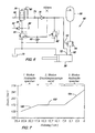
- a hydraulic circuit 60 is connected to the back-off cylinder 38 connected to the reverse soft cylinder 38 normally in Towards a fully extended position with pressure too apply, as shown in Figures 1, 3 and 6. If a sufficiently high force on the reverse soft cylinder 38th acts, allows the hydraulic circuit 60 that the Backsetting cylinder 38 merges, so that on a Obstacle hitting rod section or the Linkage sections 16, 18 backwards in the Can move back softening.
- the hydraulic circuit 60 forms a controlled pressure build-up, through which the through the Linkage introduced energy is hydraulically absorbable, before the entire stroke of remindweichzylinders 38 consumed is.
- the pressure curve is controlled by the hydraulic circuit 60, to an increase in the kinetic energy of the linkage prevent and limit strains of the linkage, so that does not affect the overall strength of the linkage is exceeded.
- the piston side end of the Reverse soft cylinder 38 via a rear or first connection 62 with a throttle or orifice 64 and with a Check valve 66 connected.
- the aperture 64 and the Check valve 66 are connected in parallel and between the Piston end of the remindweichzylinders 38 and a to about 96.5 bar (1400 psi) charged hydraulic accumulator 68 arranged.
- the Rod side of the remindweichzylinders 38 is with a Hydraulic tank 70 connected.
- An intermediate or second Connection 72 before connecting 62 near the Piston side end in the direction of the stroke of the reverse soft cylinder 38 arranged offset, is about a diaphragm 74 and a Check valve 76 with a pressure compensation valve 78th connected, which with a hydraulic source or Pump pressure line is connected to the vehicle 10.
- a differential pressure poppet valve or a pressure relief valve 82 is arranged between the Port 72 and the hydraulic tank 70.
- One Relief control valve 84 with integrated drain is controllably connected to the pressure compensation valve 78.
- a needle valve 86 Between the port 72 and the hydraulic tank 70 is a needle valve 86 arranged to release the system pressure for service purposes.
- a provided with a shutter 88 line connects the Input of the valve 84 and a pressure sensing input of the Valve 78 with a connection point between the diaphragm 74th and the check valve 76.
- the opposite pressure detecting input of the valve 78 is connected via a diaphragm 90 with an output line of the valve 78 is connected.
- a Pressure sensing line 92 of the hydraulic pump is via a Check valve 94 connected to the valve 84.
- FIG. 7 merely represents the pressure curve of the reverse cylinder for a possible Example. It goes without saying that depending on the physical properties of the linkage and the desired response numerous other pressure curves feasible are.
- valve 82 In a second or initial dodge mode when the linkage begins to move into a back softening builds the pressure in the reverse cylinder against a through the valve 82nd certain preselected pressure.
- valve 82 opens and hydraulic fluid begins through port 72 in FIG to flow the hydraulic tank.
- Through the valve 82 is in the Maintained substantially constant pressure, as in the Section 102 of the pressure curve of Figure 7 shows until the Piston of the reverse soft cylinder 38 passes through the terminal 72.
- the Hydraulic circuit 60 Due to the gradual build-up of pressure by the Hydraulic circuit 60 is created, the introduced Energy absorbed hydraulically before the backsweeper 38th has completed his entire stroke. After the obstacle was passed by the linkage section 16, 18, the drives Reverse soft cylinder 38 from to the linkage section 16, 18 in return a normal operating position.
- the valve 84 detects the reduced hydraulic system pressure and allows the pump via the valve 78, the system with pressure to Apply until normal operating pressure returns to normal System has set.
Landscapes
- Life Sciences & Earth Sciences (AREA)
- Engineering & Computer Science (AREA)
- Insects & Arthropods (AREA)
- Pest Control & Pesticides (AREA)
- Wood Science & Technology (AREA)
- Zoology (AREA)
- Environmental Sciences (AREA)
- Fluid-Pressure Circuits (AREA)
- Catching Or Destruction (AREA)
- Component Parts Of Construction Machinery (AREA)
- Operation Control Of Excavators (AREA)
- Jib Cranes (AREA)
Abstract
Description
- Fig. 1
- eine Draufsicht eines Bereichs eines landwirtschaftlichen Spritzengestänges, bei dem ein linker Gestängeabschnitt mit einem Tragrahmen verbunden ist und welches sich in einer ausgefahrenen Betriebsstellung befindet,
- Fig. 2
- eine Ansicht ähnlich zu Figur 1, wobei der linke Gestängeabschnitt in einer Rückweichstellung dargestellt ist,
- Fig. 3
- eine vergrößerte Draufsicht des Tragrahmens aus Figur 1 mit dem linken und dem rechten Gestängeabschnitt in einer vollständig ausgefahrenen Betriebsstellung,
- Fig. 4
- eine vergrößerte Draufsicht des Tragrahmens aus Figur 2 mit dem linken Gestängeabschnitt in einer Rückweichstellung und dem rechten Gestängeabschnitt in einer vollständig ausgefahrenen Betriebsstellung,
- Fig. 5
- eine Ansicht ähnlich zu Figur 4, wobei der rechte Gestängeabschnitt in einer Rückweichstellung und der linke Gestängeabschnitt in einer vollständig ausgefahrenen Betriebsstellung dargestellt ist,
- Fig. 6
- eine schematische Ansicht des im Rückweichsystem verwendeten hydraulischen Systems und
- Fig. 7
- eine Graphik mit einem Beispiel einer Druckkurve eines Rückweichzylinders.
Claims (23)
- Gestängeanordnung, mit einem Tragrahmen (12), einem Gestängeabschnitt (16, 18), welcher zum Bewegen zwischen einer Betriebsstellung und einer Rückweichstellung schwenkbar mit dem Tragrahmen (12) verbunden ist, einem hydraulischen Rückweichzylinder (38), welcher einen ersten Zustand, in der er den Gestängeabschnitt (16, 18) in seiner Betriebsstellung hält, und einen Rückweichzustand aufweist, wenn der Gestängeabschnitt (16, 18) auf ein Hindernis trifft, einer mit dem Rückweichzylinder (38) verbundenen hydraulischen Ventilanordnung (64, 66, 74, 76, 78, 82, 84, 86, 88, 90, 92, 94) und einem mit dem Rückweichzylinder verbundenen Hydraulikspeicher (68), dadurch gekennzeichnet, dass die Ventilanordnung (64, 66, 74, 76, 78, 82, 84, 86, 88, 90, 92, 94) und der Hydraulikspeicher (68) eine abgestufte Drucksteuerung des Rückweichzylinders (38) bereitstellen, derart, dass Druck erzeugt wird, um Energie zu absorbieren, sobald sich der Gestängeabschnitt (16, 18) aus der Betriebsstellung herausbewegt, wobei der abgestufte Druck zunimmt, um die Bewegungsenergie des Gestängeabschnitts (16, 18) zu absorbieren, sobald der Gestängeabschnitt (16, 18) sich der Rückweichstellung annähert.
- Gestängeanordnung nach Anspruch 1, dadurch gekennzeichnet, dass der Gestängeabschnitt (16, 18) einen inneren Abschnitt eines landwirtschaftlichen Spritzengestänges umfasst.
- Gestängeanordnung nach Anspruch 1 oder 2, dadurch gekennzeichnet, dass die Ventilanordnung (64, 66, 74, 76, 78, 82, 84, 86, 88, 90, 92, 94) und der Hydraulikspeicher (68) mit einem Ende des Rückweichzylinders (38) verbunden sind, wobei der Rückweichzylinder (38) einen ausgefahrenen Zustand einnimmt, wenn der Gestängeabschnitt (16, 18) in der Betriebsstellung ist, und einen zusammengefahrenen Zustand einnimmt, wenn der Gestängeabschnitt (16, 18) in der Rückweichstellung ist.
- Gestängeanordnung nach einem der Ansprüche 1 bis 3, dadurch gekennzeichnet, dass der Hydraulikspeicher (68) und die Ventilanordnung (64, 66, 74, 76, 78, 82, 84, 86, 88, 90, 92, 94) eine erste Stufe definieren, in der der Hydraulikspeicher (68) Energie des Gestängeabschnitts (16, 18) absorbiert, wenn der Gestängeabschnitt (16, 18) auf das Hindernis trifft.
- Gestängeanordnung nach einem der Ansprüche 1 bis 4, dadurch gekennzeichnet, dass der Hydraulikspeicher (68) und die Ventilanordnung (64, 66, 74, 76, 78, 82, 84, 86, 88, 90, 92, 94) eine volle Rückweichstufe definieren, in der der Hydraulikspeicher Energie des Gestängeabschnitts (16, 18) absorbiert, wenn der Gestängeabschnitt (16, 18) sich der Rückweichstellung annähert.
- Gestängeanordnung nach einem der Ansprüche 1 bis 5, dadurch gekennzeichnet, dass der Hydraulikspeicher (68) und die Ventilanordnung (64, 66, 74, 76, 78, 82, 84, 86, 88, 90, 92, 94) eine Zwischenstufe definieren, in der die Ventilanordnung (64, 66, 74, 76, 78, 82, 84, 86, 88, 90, 92, 94) einen Fließwiderstand gegen hydraulische Flüssigkeit aus dem Rückweichzylinder (38) erzeugt, um Energie des Gestängeabschnitt s (16, 18) zu absorbieren, wenn der Gestängeabschnitt (16, 18) sich zwischen der Betriebsstellung und der Rückweichstellung befindet.
- Gestängeanordnung nach einem der Ansprüche 1 bis 6, dadurch gekennzeichnet, dass während wenigstens einer der Stufen die Ventilanordnung (64, 66, 74, 76, 78, 82, 84, 86, 88, 90, 92, 94) die Absorption der Energie des Gestängeabschnitts steuert und während einer anderen Stufe die Absorption der Energie des Gestängeabschnitts (16, 18) durch den Hydraulikspeicher (68) erfolgt.
- Gestängeanordnung nach einem der Ansprüche 1 bis 7, dadurch gekennzeichnet, dass die Ventilanordnung (64, 66, 74, 76, 78, 82, 84, 86, 88, 90, 92, 94) in einer Zwischenstellung des Gestängeabschnitts (16, 18) die Absorption der Energie bewirkt, indem in der Zwischenstellung der hydraulische Fluss relativ zum Rückweichzylinder (38) begrenzt wird, und der Hydraulikspeicher (68) die Absorption der Energie bewirkt, wenn sich der Gestängeabschnitt (16, 18) der Rückweichstellung nähert.
- Gestängeanordnung nach einem der Ansprüche 1 bis 8, dadurch gekennzeichnet, dass die Ventilanordnung (64, 66, 74, 76, 78, 82, 84, 86, 88, 90, 92, 94) in der Zwischenstellung des Gestängeabschnitts (16, 18) die Absorption der Energie bewirkt, indem in der Zwischenstellung der hydraulische Fluss relativ zum Rückweichzylinder (38) begrenzt wird, und der Hydraulikspeicher (68) Eine Anfangs-Absorption der Energie bewirkt, wenn der Gestängeabschnitt (16, 18) auf ein Hindernis trifft und beginnt, sich aus der Betriebsstellung heraus zu bewegen.
- Gestängeanordnung nach einem der Ansprüche 1 bis 9, dadurch gekennzeichnet, dass die Ventilanordnung (64, 66, 74, 76, 78, 82, 84, 86, 88, 90, 92, 94) ein mit dem Rückweichzylinder (38) verbundenes und auf den Druck im Rückweichzylinder (38) ansprechendes Druckbegrenzungsventil (82) umfasst, wobei der Hydraulikspeicher (68) im Wesentlichen die gesamte Energie absorbiert, bis das Druckbegrenzungsventil (82) auf einen zunehmenden Druck im Rückweichzylinder (38) anspricht.
- Gestängeanordnung nach einem der Ansprüche 1 bis 10, dadurch gekennzeichnet, dass ein zweiter Gestängeabschnitt (16, 18) enthalten ist, welcher schwenkbar mit dem Tragrahmen (12) und mit dem Rückweichzylinder (38) verbunden ist, wobei der Hydraulikspeicher (68) und die Ventilanordnung (64, 66, 74, 76, 78, 82, 84, 86, 88, 90, 92, 94) eine Absorption der Energie des zweiten Gestängeabschnitts (16, 18) bewirken, wenn der zweite Gestängeabschnitt (16, 18) auf ein Hindernis trifft.
- Gestängeanordnung nach Anspruch 11, dadurch gekennzeichnet, dass eine Wipphebelanordnung (32, 34) vorgesehen ist, welche die Gestängeabschnitte (16, 18) mit dem Rückweichzylinder (38) verbindet.
- Gestängeanordnung nach Anspruch 12, dadurch gekennzeichnet, dass eine Faltzylinderanordnung (26, 28) vorgesehen sind, welche mit der Wipphebelanordnung (32, 34) und den Gestängeabschnitten (16, 18) verbunden ist, um die Gestängeabschnitte (16, 18) aus der Betriebsstellung in eine gefaltete Transportstellung zu bewegen.
- Gestängeanordnung nach einem der Ansprüche 10 bis 13, dadurch gekennzeichnet, dass Mittel (62, 72) vorgesehen sind, welche die Ventilanordnung (64, 66, 74, 76, 78, 82, 84, 86, 88, 90, 92, 94) und den Hydraulikspeicher (68) mit dem Rückweichzylinder (38) verbinden.
- Gestängeanordnung nach einem der Ansprüche 10 bis 14, dadurch gekennzeichnet, dass die Mittel einen ersten Anschluss (62) am Rückweichzylinder (38), der mit dem Hydraulikspeicher (68) verbunden ist, und einen zweiten Anschluss (72) am Rückweichzylinder (38) aufweisen, der mit dem Druckbegrenzungsventil (82) verbunden ist, wobei die Anschlüsse über erste und zweite hydraulische Leitungen mit dem Rückweichzylinder (38) bzw. dem Druckbegrenzungsventil (82) verbunden sind.
- Gestängeanordnung nach Anspruch 15, dadurch gekennzeichnet, dass der Rückweichzylinder (38) einen Hubweg aufweist und die Anschlüsse (62, 72) entlang des Hubwegs des Rückweichzylinders (38) versetzt angeordnet sind.
- Gestängeanordnung nach Anspruch 16, dadurch gekennzeichnet, dass wenigstens einer der ersten und zweiten Anschlüsse (62, 72) während eines Abschnitts des Hubwegs blockierbar ist.
- Gestängeanordnung nach einem der Ansprüche 16 oder 17, dadurch gekennzeichnet, dass der erste Anschluss (62) mit dem Hydraulikspeicher (68) und der zweite Anschluss (72) mit dem Druckbegrenzungsventil (82) verbunden ist, wobei der zweite Anschluss (72) ausgehend vom ersten Anschluss (62) in Richtung des Hubwegs versetzt angeordnet ist.
- Gestängeanordnung nach einem der Ansprüche 16 bis 18, dadurch gekennzeichnet, dass der erste Anschluss (62) im Wesentlichen während des gesamten Hubwegs frei liegt und der zweite Anschluss (72) blockiert ist, wenn sich der Gestängeabschnitt (16, 18) der Rückweichstellung nähert.
- Gestängeanordnung nach einem der Ansprüche 16 bis 19, dadurch gekennzeichnet, dass das Druckbegrenzungsventil (82) über einen Abschnitt des Hubwegs den Druck im Rückweichzylinder (38) steuert und der Hydraulikspeicher (68) einen ansteigenden Druck im Rückweichzylinder (38) nahe eines Extrempunktes des Hubwegs bereitstellt.
- Gestängeanordnung nach Anspruch 20, dadurch gekennzeichnet, dass Mittel vorgesehen sind, durch welche die Ventilanordnung (64, 66, 74, 76, 78, 82, 84, 86, 88, 90, 92, 94) nahe des Extrempunktes des Hubwegs blockierbar sind.
- Gestängeanordnung nach einem der Ansprüche 16 bis 21, dadurch gekennzeichnet, dass der Hydraulikspeicher (68) einen ansteigenden Druck im Rückweichzylinder (38) bei erreichen eines Anfangspunkts und bei Erreichen eines Endpunkts des Hubwegs bereitstellt und die Ventilanordnung (64, 66, 74, 76, 78, 82, 84, 86, 88, 90, 92, 94) während eines Zwischenbereichs des Hubwegs einen Druck im Rückweichzylinder (38) definiert.
- Gestängeanordnung nach einem der Ansprüche 1 bis 22, dadurch gekennzeichnet, dass der Rückweichzylinder (38) den Gestängeabschnitt in die Betriebsstellung vorspannt.
Applications Claiming Priority (2)
| Application Number | Priority Date | Filing Date | Title |
|---|---|---|---|
| US786689 | 2004-02-25 | ||
| US10/786,689 US7073735B2 (en) | 2004-02-25 | 2004-02-25 | Boom breakaway system |
Publications (2)
| Publication Number | Publication Date |
|---|---|
| EP1568274A1 true EP1568274A1 (de) | 2005-08-31 |
| EP1568274B1 EP1568274B1 (de) | 2007-10-24 |
Family
ID=34750494
Family Applications (1)
| Application Number | Title | Priority Date | Filing Date |
|---|---|---|---|
| EP05101099A Expired - Lifetime EP1568274B1 (de) | 2004-02-25 | 2005-02-15 | Gestängeanordnung |
Country Status (8)
| Country | Link |
|---|---|
| US (1) | US7073735B2 (de) |
| EP (1) | EP1568274B1 (de) |
| AR (1) | AR047968A1 (de) |
| AT (1) | ATE376355T1 (de) |
| BR (1) | BRPI0500547B1 (de) |
| DE (1) | DE502005001758D1 (de) |
| DK (1) | DK1568274T3 (de) |
| ES (1) | ES2292055T3 (de) |
Cited By (3)
| Publication number | Priority date | Publication date | Assignee | Title |
|---|---|---|---|---|
| CN105104342A (zh) * | 2015-08-21 | 2015-12-02 | 樱田农机科技(泰州)有限公司 | 弹性缓冲式植保喷药喷肥机折叠式管道支承杆 |
| EP3053438A1 (de) * | 2015-02-03 | 2016-08-10 | Amazonen-Werke H. Dreyer GmbH & Co. KG | Verteilergestänge |
| EP3443840A1 (de) * | 2017-08-18 | 2019-02-20 | Amazonen-Werke H. Dreyer GmbH & Co. KG | Verteilergestänge |
Families Citing this family (17)
| Publication number | Priority date | Publication date | Assignee | Title |
|---|---|---|---|---|
| US7740190B2 (en) * | 2005-05-31 | 2010-06-22 | Agco Corporation | Boom breakaway assembly |
| US7823803B2 (en) * | 2007-08-21 | 2010-11-02 | Agco Corporation | Integrated breakaway cylinder and method for constructing a boom assembly |
| US8453947B2 (en) * | 2009-09-25 | 2013-06-04 | Charles H. Martin | Agricultural vehicle and system |
| WO2012087893A1 (en) | 2010-12-20 | 2012-06-28 | Agco Corporation | Boom fore and aft breakaway assembly |
| CN102091682B (zh) * | 2010-12-24 | 2012-07-04 | 江苏大学 | 自平衡喷杆喷雾机 |
| JP5801618B2 (ja) * | 2011-06-21 | 2015-10-28 | カヤバ工業株式会社 | ブームスプレーヤ及びブーム制振装置 |
| US9408379B2 (en) * | 2013-10-08 | 2016-08-09 | Agco Corporation | Bi-directional break-away boom with roller and rotary damper |
| US10258028B2 (en) * | 2015-04-27 | 2019-04-16 | Cnh Industrial America Llc | Sprayer boom with perforated outer walls |
| US10188092B2 (en) | 2015-04-28 | 2019-01-29 | Cnh Industrial America Llc | Breakaway adapter system facilitating both front-mounted and rear-mounted configurations of a sprayer boom |
| US10687523B2 (en) | 2015-04-30 | 2020-06-23 | Cnh Industrial America Llc | Breakaway boom segment with perforated outer walls |
| JP6514594B2 (ja) * | 2015-07-21 | 2019-05-15 | Kyb株式会社 | ブーム昇降装置及びブームスプレーヤ |
| JP6637369B2 (ja) * | 2016-04-08 | 2020-01-29 | Kyb株式会社 | ブーム制振装置及びブームスプレーヤ |
| DE102017104804A1 (de) | 2017-03-08 | 2018-09-13 | Amazonen-Werke H. Dreyer Gmbh & Co. Kg | Steuer- und/oder Regelsystem, landwirtschaftliches Nutzfahrzeug und Verfahren zur Steuerung und/oder Regelung eines landwirtschaftlichen Nutzfahrzeuges |
| EP3629725B1 (de) * | 2017-05-23 | 2021-03-31 | FSP Fluid Systems Partners Holding AG | Steuereinrichtung für eine ausbringvorrichtung und ausbringvorrichtung mit einer steuereinrichtung |
| WO2019027713A1 (en) | 2017-08-01 | 2019-02-07 | Valmont Industries, Inc. | PROTECTIVE BELLOW SET FOR IRRIGATION |
| US10405505B2 (en) | 2017-08-10 | 2019-09-10 | Valmont Industries, Inc. | System and method for variable rate, high speed irrigation control |
| US11140838B2 (en) | 2017-08-10 | 2021-10-12 | Valmont Industries, Inc. | System and method for variable rate, high speed irrigation control |
Citations (3)
| Publication number | Priority date | Publication date | Assignee | Title |
|---|---|---|---|---|
| US4344572A (en) * | 1980-06-18 | 1982-08-17 | Tyler Loren E | Positioning apparatus for boom structures |
| US5000385A (en) * | 1989-08-16 | 1991-03-19 | Clark Equipment Company | Spray boom breakaway apparatus |
| US6293475B1 (en) * | 2000-01-31 | 2001-09-25 | Summers Manufacturing Co., Inc. | Foldable boom for an agricultural sprayer |
Family Cites Families (10)
| Publication number | Priority date | Publication date | Assignee | Title |
|---|---|---|---|---|
| US3949539A (en) * | 1971-12-22 | 1976-04-13 | Cartner Jack O | Hydraulic mower attachment |
| US4168800A (en) * | 1977-12-30 | 1979-09-25 | Allied Products Corporation | Combination hydraulic cylinder and shock absorber |
| US4183195A (en) * | 1978-08-22 | 1980-01-15 | Terrain King Corporation | Mounting apparatus for offset mower |
| US4506464A (en) * | 1982-09-10 | 1985-03-26 | Cartner Jack O | Hydraulic breakaway system for mobile cutting apparatus |
| US4986010A (en) * | 1989-03-13 | 1991-01-22 | Cartner Jack O | Sloper apparatus |
| GB2311922A (en) * | 1996-04-09 | 1997-10-15 | Benest Eng Ltd | Controlling the movement of a boom on an agriculturtal implement |
| US6059201A (en) * | 1998-07-29 | 2000-05-09 | Equipment Technologies, Llc | Boom arm segment release mechanism for a crop sprayer |
| CA2538941C (en) * | 1998-10-30 | 2007-07-31 | Cnh Canada, Ltd./Cnh Canada, Ltee. | Field marker for agricultural implement |
| US6119963A (en) * | 1999-07-30 | 2000-09-19 | Case Corporation | Full boom pivot breakaway |
| US6581639B2 (en) * | 2000-10-20 | 2003-06-24 | Case Corporation | Low leak boom control check valve |
-
2004
- 2004-02-25 US US10/786,689 patent/US7073735B2/en not_active Expired - Lifetime
-
2005
- 2005-02-15 DE DE502005001758T patent/DE502005001758D1/de not_active Expired - Lifetime
- 2005-02-15 DK DK05101099T patent/DK1568274T3/da active
- 2005-02-15 ES ES05101099T patent/ES2292055T3/es not_active Expired - Lifetime
- 2005-02-15 AT AT05101099T patent/ATE376355T1/de not_active IP Right Cessation
- 2005-02-15 EP EP05101099A patent/EP1568274B1/de not_active Expired - Lifetime
- 2005-02-22 AR ARP050100636A patent/AR047968A1/es not_active Application Discontinuation
- 2005-02-23 BR BRPI0500547-7A patent/BRPI0500547B1/pt not_active IP Right Cessation
Patent Citations (3)
| Publication number | Priority date | Publication date | Assignee | Title |
|---|---|---|---|---|
| US4344572A (en) * | 1980-06-18 | 1982-08-17 | Tyler Loren E | Positioning apparatus for boom structures |
| US5000385A (en) * | 1989-08-16 | 1991-03-19 | Clark Equipment Company | Spray boom breakaway apparatus |
| US6293475B1 (en) * | 2000-01-31 | 2001-09-25 | Summers Manufacturing Co., Inc. | Foldable boom for an agricultural sprayer |
Cited By (3)
| Publication number | Priority date | Publication date | Assignee | Title |
|---|---|---|---|---|
| EP3053438A1 (de) * | 2015-02-03 | 2016-08-10 | Amazonen-Werke H. Dreyer GmbH & Co. KG | Verteilergestänge |
| CN105104342A (zh) * | 2015-08-21 | 2015-12-02 | 樱田农机科技(泰州)有限公司 | 弹性缓冲式植保喷药喷肥机折叠式管道支承杆 |
| EP3443840A1 (de) * | 2017-08-18 | 2019-02-20 | Amazonen-Werke H. Dreyer GmbH & Co. KG | Verteilergestänge |
Also Published As
| Publication number | Publication date |
|---|---|
| US7073735B2 (en) | 2006-07-11 |
| AR047968A1 (es) | 2006-03-15 |
| US20050184175A1 (en) | 2005-08-25 |
| DK1568274T3 (da) | 2008-02-25 |
| BRPI0500547A (pt) | 2005-10-18 |
| ES2292055T3 (es) | 2008-03-01 |
| BRPI0500547B1 (pt) | 2017-11-07 |
| EP1568274B1 (de) | 2007-10-24 |
| DE502005001758D1 (de) | 2007-12-06 |
| ATE376355T1 (de) | 2007-11-15 |
Similar Documents
| Publication | Publication Date | Title |
|---|---|---|
| EP1568274B1 (de) | Gestängeanordnung | |
| EP2064948B1 (de) | Spritzengestänge | |
| EP2238071B1 (de) | Fahrbare arbeitsmaschine | |
| EP2240360B1 (de) | Fahrbare arbeitsmaschine | |
| DE1013532B (de) | Fahrzeugaufhaengung | |
| EP1813730A2 (de) | Frontlader und Traktorkabine für einen Traktor | |
| DE3439048A1 (de) | Kraftheber fuer ein hubgeraet | |
| DE4335511A1 (de) | Sicherheitsvorrichtung für den Fahrer eines Fahrzeugs mit Lenkung und Pedal | |
| EP3053438A1 (de) | Verteilergestänge | |
| EP2311318B1 (de) | Vorrichtung zur Aufhängung und Führung von Arbeitsorganen einer landwirtschaftlichen Maschine | |
| DE3305758A1 (de) | Knickschutzsteuerung | |
| DE202015107017U1 (de) | Mitgehflurförderzeug | |
| DE202014002808U1 (de) | Landwirtschaftliche Maschine | |
| EP4551001A1 (de) | Mähvorrichtung für ein trägerfahrzeug | |
| WO2021037519A1 (de) | Landwirtschaftliches gerät mit verbesserter aufhängung | |
| DE2600250A1 (de) | Mehrscharenpflug | |
| EP0176084B1 (de) | Maschine zum seitlichen Ausbringen von insbesondere körnigem Material | |
| DE102021204032B4 (de) | Hydraulische Steuereinheit für einen Bootsantrieb und Bootsantrieb mit einer solchen Steuereinheit | |
| AT502053B1 (de) | Anbauvorrichtung für eine landmaschine | |
| EP2213528A2 (de) | Dämpfungseinrichtung an einer Frontklappe eines Kraftfahrzeugs | |
| DE102016119054A1 (de) | Steuersystem, landwirtschaftliches Nutzfahrzeug und Verfahren zur Steuerung eines landwirtschaftlichen Nutzfahrzeugs | |
| DE102020207104B4 (de) | Hydraulische Powertrimm-Lift-Vorrichtung für einen Bootantrieb und Bootantrieb | |
| DE102006045270B3 (de) | Mähmaschine | |
| EP3449715A1 (de) | Landwirtschaftliches fahrzeug sowie raupenfahrwerk für ein landwirtschaftliches fahrzeug | |
| DE2717388A1 (de) | Hydropneumatische federung, insbesondere fuer die hinterachse von radladern oder dergleichen mit verriegelbarer vorderachse |
Legal Events
| Date | Code | Title | Description |
|---|---|---|---|
| PUAI | Public reference made under article 153(3) epc to a published international application that has entered the european phase |
Free format text: ORIGINAL CODE: 0009012 |
|
| AK | Designated contracting states |
Kind code of ref document: A1 Designated state(s): AT BE BG CH CY CZ DE DK EE ES FI FR GB GR HU IE IS IT LI LT LU MC NL PL PT RO SE SI SK TR |
|
| AX | Request for extension of the european patent |
Extension state: AL BA HR LV MK YU |
|
| 17P | Request for examination filed |
Effective date: 20060228 |
|
| AKX | Designation fees paid |
Designated state(s): AT BE BG CH CY CZ DE DK EE ES FI FR GB GR HU IE IS IT LI LT LU MC NL PL PT RO SE SI SK TR |
|
| GRAP | Despatch of communication of intention to grant a patent |
Free format text: ORIGINAL CODE: EPIDOSNIGR1 |
|
| GRAS | Grant fee paid |
Free format text: ORIGINAL CODE: EPIDOSNIGR3 |
|
| GRAA | (expected) grant |
Free format text: ORIGINAL CODE: 0009210 |
|
| AK | Designated contracting states |
Kind code of ref document: B1 Designated state(s): AT BE BG CH CY CZ DE DK EE ES FI FR GB GR HU IE IS IT LI LT LU MC NL PL PT RO SE SI SK TR |
|
| REG | Reference to a national code |
Ref country code: GB Ref legal event code: FG4D Free format text: NOT ENGLISH |
|
| REG | Reference to a national code |
Ref country code: CH Ref legal event code: EP |
|
| REG | Reference to a national code |
Ref country code: IE Ref legal event code: FG4D Free format text: LANGUAGE OF EP DOCUMENT: GERMAN |
|
| REF | Corresponds to: |
Ref document number: 502005001758 Country of ref document: DE Date of ref document: 20071206 Kind code of ref document: P |
|
| GBT | Gb: translation of ep patent filed (gb section 77(6)(a)/1977) |
Effective date: 20080104 |
|
| REG | Reference to a national code |
Ref country code: DK Ref legal event code: T3 |
|
| REG | Reference to a national code |
Ref country code: ES Ref legal event code: FG2A Ref document number: 2292055 Country of ref document: ES Kind code of ref document: T3 |
|
| PG25 | Lapsed in a contracting state [announced via postgrant information from national office to epo] |
Ref country code: SE Free format text: LAPSE BECAUSE OF FAILURE TO SUBMIT A TRANSLATION OF THE DESCRIPTION OR TO PAY THE FEE WITHIN THE PRESCRIBED TIME-LIMIT Effective date: 20080124 |
|
| PG25 | Lapsed in a contracting state [announced via postgrant information from national office to epo] |
Ref country code: IS Free format text: LAPSE BECAUSE OF FAILURE TO SUBMIT A TRANSLATION OF THE DESCRIPTION OR TO PAY THE FEE WITHIN THE PRESCRIBED TIME-LIMIT Effective date: 20080224 Ref country code: BG Free format text: LAPSE BECAUSE OF FAILURE TO SUBMIT A TRANSLATION OF THE DESCRIPTION OR TO PAY THE FEE WITHIN THE PRESCRIBED TIME-LIMIT Effective date: 20080124 Ref country code: SI Free format text: LAPSE BECAUSE OF FAILURE TO SUBMIT A TRANSLATION OF THE DESCRIPTION OR TO PAY THE FEE WITHIN THE PRESCRIBED TIME-LIMIT Effective date: 20071024 Ref country code: LT Free format text: LAPSE BECAUSE OF FAILURE TO SUBMIT A TRANSLATION OF THE DESCRIPTION OR TO PAY THE FEE WITHIN THE PRESCRIBED TIME-LIMIT Effective date: 20071024 Ref country code: PL Free format text: LAPSE BECAUSE OF FAILURE TO SUBMIT A TRANSLATION OF THE DESCRIPTION OR TO PAY THE FEE WITHIN THE PRESCRIBED TIME-LIMIT Effective date: 20071024 Ref country code: PT Free format text: LAPSE BECAUSE OF FAILURE TO SUBMIT A TRANSLATION OF THE DESCRIPTION OR TO PAY THE FEE WITHIN THE PRESCRIBED TIME-LIMIT Effective date: 20080324 |
|
| REG | Reference to a national code |
Ref country code: IE Ref legal event code: FD4D |
|
| ET | Fr: translation filed | ||
| REG | Reference to a national code |
Ref country code: HU Ref legal event code: AG4A Ref document number: E002904 Country of ref document: HU |
|
| PG25 | Lapsed in a contracting state [announced via postgrant information from national office to epo] |
Ref country code: CZ Free format text: LAPSE BECAUSE OF FAILURE TO SUBMIT A TRANSLATION OF THE DESCRIPTION OR TO PAY THE FEE WITHIN THE PRESCRIBED TIME-LIMIT Effective date: 20071024 |
|
| PG25 | Lapsed in a contracting state [announced via postgrant information from national office to epo] |
Ref country code: SK Free format text: LAPSE BECAUSE OF FAILURE TO SUBMIT A TRANSLATION OF THE DESCRIPTION OR TO PAY THE FEE WITHIN THE PRESCRIBED TIME-LIMIT Effective date: 20071024 Ref country code: RO Free format text: LAPSE BECAUSE OF FAILURE TO SUBMIT A TRANSLATION OF THE DESCRIPTION OR TO PAY THE FEE WITHIN THE PRESCRIBED TIME-LIMIT Effective date: 20071024 |
|
| PLBE | No opposition filed within time limit |
Free format text: ORIGINAL CODE: 0009261 |
|
| STAA | Information on the status of an ep patent application or granted ep patent |
Free format text: STATUS: NO OPPOSITION FILED WITHIN TIME LIMIT |
|
| 26N | No opposition filed |
Effective date: 20080725 |
|
| PG25 | Lapsed in a contracting state [announced via postgrant information from national office to epo] |
Ref country code: MC Free format text: LAPSE BECAUSE OF NON-PAYMENT OF DUE FEES Effective date: 20080228 Ref country code: IE Free format text: LAPSE BECAUSE OF FAILURE TO SUBMIT A TRANSLATION OF THE DESCRIPTION OR TO PAY THE FEE WITHIN THE PRESCRIBED TIME-LIMIT Effective date: 20071024 |
|
| PG25 | Lapsed in a contracting state [announced via postgrant information from national office to epo] |
Ref country code: EE Free format text: LAPSE BECAUSE OF FAILURE TO SUBMIT A TRANSLATION OF THE DESCRIPTION OR TO PAY THE FEE WITHIN THE PRESCRIBED TIME-LIMIT Effective date: 20071024 Ref country code: GR Free format text: LAPSE BECAUSE OF FAILURE TO SUBMIT A TRANSLATION OF THE DESCRIPTION OR TO PAY THE FEE WITHIN THE PRESCRIBED TIME-LIMIT Effective date: 20080125 |
|
| PG25 | Lapsed in a contracting state [announced via postgrant information from national office to epo] |
Ref country code: FI Free format text: LAPSE BECAUSE OF FAILURE TO SUBMIT A TRANSLATION OF THE DESCRIPTION OR TO PAY THE FEE WITHIN THE PRESCRIBED TIME-LIMIT Effective date: 20071024 |
|
| PG25 | Lapsed in a contracting state [announced via postgrant information from national office to epo] |
Ref country code: AT Free format text: LAPSE BECAUSE OF NON-PAYMENT OF DUE FEES Effective date: 20080215 |
|
| PG25 | Lapsed in a contracting state [announced via postgrant information from national office to epo] |
Ref country code: CY Free format text: LAPSE BECAUSE OF FAILURE TO SUBMIT A TRANSLATION OF THE DESCRIPTION OR TO PAY THE FEE WITHIN THE PRESCRIBED TIME-LIMIT Effective date: 20071024 |
|
| REG | Reference to a national code |
Ref country code: CH Ref legal event code: PL |
|
| PG25 | Lapsed in a contracting state [announced via postgrant information from national office to epo] |
Ref country code: CH Free format text: LAPSE BECAUSE OF NON-PAYMENT OF DUE FEES Effective date: 20090228 Ref country code: LI Free format text: LAPSE BECAUSE OF NON-PAYMENT OF DUE FEES Effective date: 20090228 |
|
| PG25 | Lapsed in a contracting state [announced via postgrant information from national office to epo] |
Ref country code: LU Free format text: LAPSE BECAUSE OF NON-PAYMENT OF DUE FEES Effective date: 20080215 |
|
| PG25 | Lapsed in a contracting state [announced via postgrant information from national office to epo] |
Ref country code: TR Free format text: LAPSE BECAUSE OF FAILURE TO SUBMIT A TRANSLATION OF THE DESCRIPTION OR TO PAY THE FEE WITHIN THE PRESCRIBED TIME-LIMIT Effective date: 20071024 |
|
| PGFP | Annual fee paid to national office [announced via postgrant information from national office to epo] |
Ref country code: IT Payment date: 20110223 Year of fee payment: 7 |
|
| PG25 | Lapsed in a contracting state [announced via postgrant information from national office to epo] |
Ref country code: IT Free format text: LAPSE BECAUSE OF NON-PAYMENT OF DUE FEES Effective date: 20120215 |
|
| PGFP | Annual fee paid to national office [announced via postgrant information from national office to epo] |
Ref country code: DK Payment date: 20140225 Year of fee payment: 10 |
|
| PGFP | Annual fee paid to national office [announced via postgrant information from national office to epo] |
Ref country code: BE Payment date: 20140228 Year of fee payment: 10 Ref country code: ES Payment date: 20140226 Year of fee payment: 10 Ref country code: HU Payment date: 20140124 Year of fee payment: 10 |
|
| PG25 | Lapsed in a contracting state [announced via postgrant information from national office to epo] |
Ref country code: BE Free format text: LAPSE BECAUSE OF NON-PAYMENT OF DUE FEES Effective date: 20150228 |
|
| REG | Reference to a national code |
Ref country code: DK Ref legal event code: EBP Effective date: 20150228 |
|
| PG25 | Lapsed in a contracting state [announced via postgrant information from national office to epo] |
Ref country code: HU Free format text: LAPSE BECAUSE OF NON-PAYMENT OF DUE FEES Effective date: 20150216 |
|
| PG25 | Lapsed in a contracting state [announced via postgrant information from national office to epo] |
Ref country code: DK Free format text: LAPSE BECAUSE OF NON-PAYMENT OF DUE FEES Effective date: 20150228 |
|
| REG | Reference to a national code |
Ref country code: FR Ref legal event code: PLFP Year of fee payment: 12 |
|
| REG | Reference to a national code |
Ref country code: ES Ref legal event code: FD2A Effective date: 20160602 |
|
| PG25 | Lapsed in a contracting state [announced via postgrant information from national office to epo] |
Ref country code: ES Free format text: LAPSE BECAUSE OF NON-PAYMENT OF DUE FEES Effective date: 20150216 |
|
| REG | Reference to a national code |
Ref country code: FR Ref legal event code: PLFP Year of fee payment: 13 |
|
| PGFP | Annual fee paid to national office [announced via postgrant information from national office to epo] |
Ref country code: DE Payment date: 20170119 Year of fee payment: 13 Ref country code: FR Payment date: 20170223 Year of fee payment: 13 |
|
| PGFP | Annual fee paid to national office [announced via postgrant information from national office to epo] |
Ref country code: NL Payment date: 20170226 Year of fee payment: 13 Ref country code: GB Payment date: 20170227 Year of fee payment: 13 |
|
| REG | Reference to a national code |
Ref country code: DE Ref legal event code: R119 Ref document number: 502005001758 Country of ref document: DE |
|
| REG | Reference to a national code |
Ref country code: NL Ref legal event code: MM Effective date: 20180301 |
|
| GBPC | Gb: european patent ceased through non-payment of renewal fee |
Effective date: 20180215 |
|
| REG | Reference to a national code |
Ref country code: FR Ref legal event code: ST Effective date: 20181031 |
|
| PG25 | Lapsed in a contracting state [announced via postgrant information from national office to epo] |
Ref country code: NL Free format text: LAPSE BECAUSE OF NON-PAYMENT OF DUE FEES Effective date: 20180301 |
|
| PG25 | Lapsed in a contracting state [announced via postgrant information from national office to epo] |
Ref country code: DE Free format text: LAPSE BECAUSE OF NON-PAYMENT OF DUE FEES Effective date: 20180901 |
|
| PG25 | Lapsed in a contracting state [announced via postgrant information from national office to epo] |
Ref country code: GB Free format text: LAPSE BECAUSE OF NON-PAYMENT OF DUE FEES Effective date: 20180215 Ref country code: FR Free format text: LAPSE BECAUSE OF NON-PAYMENT OF DUE FEES Effective date: 20180228 |