EP1568186B1 - Procede d'analyse de la reponse impulsionnelle d'un canal de transmission - Google Patents
Procede d'analyse de la reponse impulsionnelle d'un canal de transmission Download PDFInfo
- Publication number
- EP1568186B1 EP1568186B1 EP03767534A EP03767534A EP1568186B1 EP 1568186 B1 EP1568186 B1 EP 1568186B1 EP 03767534 A EP03767534 A EP 03767534A EP 03767534 A EP03767534 A EP 03767534A EP 1568186 B1 EP1568186 B1 EP 1568186B1
- Authority
- EP
- European Patent Office
- Prior art keywords
- impulse response
- channel impulse
- discrete
- log
- channel
- Prior art date
- Legal status (The legal status is an assumption and is not a legal conclusion. Google has not performed a legal analysis and makes no representation as to the accuracy of the status listed.)
- Expired - Lifetime
Links
- 230000004044 response Effects 0.000 title claims description 71
- 230000005540 biological transmission Effects 0.000 title claims description 62
- 238000000034 method Methods 0.000 title claims description 54
- 239000013598 vector Substances 0.000 claims description 34
- 238000004364 calculation method Methods 0.000 claims description 13
- 230000015572 biosynthetic process Effects 0.000 claims description 9
- 230000003044 adaptive effect Effects 0.000 claims description 5
- 230000001419 dependent effect Effects 0.000 claims description 5
- 238000005259 measurement Methods 0.000 claims description 5
- 238000006243 chemical reaction Methods 0.000 claims description 4
- 238000009795 derivation Methods 0.000 claims 7
- 238000001228 spectrum Methods 0.000 description 23
- 238000005070 sampling Methods 0.000 description 20
- 238000012546 transfer Methods 0.000 description 18
- 230000009466 transformation Effects 0.000 description 17
- 230000002123 temporal effect Effects 0.000 description 13
- 230000003111 delayed effect Effects 0.000 description 11
- 238000012545 processing Methods 0.000 description 7
- 238000004422 calculation algorithm Methods 0.000 description 4
- 230000000694 effects Effects 0.000 description 4
- 238000002592 echocardiography Methods 0.000 description 3
- 238000010606 normalization Methods 0.000 description 3
- 238000005457 optimization Methods 0.000 description 3
- RLLPVAHGXHCWKJ-IEBWSBKVSA-N (3-phenoxyphenyl)methyl (1s,3s)-3-(2,2-dichloroethenyl)-2,2-dimethylcyclopropane-1-carboxylate Chemical compound CC1(C)[C@H](C=C(Cl)Cl)[C@@H]1C(=O)OCC1=CC=CC(OC=2C=CC=CC=2)=C1 RLLPVAHGXHCWKJ-IEBWSBKVSA-N 0.000 description 2
- 238000013459 approach Methods 0.000 description 2
- 238000004590 computer program Methods 0.000 description 2
- 238000010586 diagram Methods 0.000 description 2
- 230000009467 reduction Effects 0.000 description 2
- 230000003595 spectral effect Effects 0.000 description 2
- NAWXUBYGYWOOIX-SFHVURJKSA-N (2s)-2-[[4-[2-(2,4-diaminoquinazolin-6-yl)ethyl]benzoyl]amino]-4-methylidenepentanedioic acid Chemical compound C1=CC2=NC(N)=NC(N)=C2C=C1CCC1=CC=C(C(=O)N[C@@H](CC(=C)C(O)=O)C(O)=O)C=C1 NAWXUBYGYWOOIX-SFHVURJKSA-N 0.000 description 1
- 238000012952 Resampling Methods 0.000 description 1
- 241000542420 Sphyrna tudes Species 0.000 description 1
- 238000007792 addition Methods 0.000 description 1
- 230000002238 attenuated effect Effects 0.000 description 1
- 230000008901 benefit Effects 0.000 description 1
- 230000001934 delay Effects 0.000 description 1
- 238000001514 detection method Methods 0.000 description 1
- 238000011161 development Methods 0.000 description 1
- 230000018109 developmental process Effects 0.000 description 1
- 239000012535 impurity Substances 0.000 description 1
- 238000007620 mathematical function Methods 0.000 description 1
- 238000002360 preparation method Methods 0.000 description 1
- 238000006467 substitution reaction Methods 0.000 description 1
- 230000001360 synchronised effect Effects 0.000 description 1
- 238000012360 testing method Methods 0.000 description 1
- 238000011144 upstream manufacturing Methods 0.000 description 1
- XLYOFNOQVPJJNP-UHFFFAOYSA-N water Substances O XLYOFNOQVPJJNP-UHFFFAOYSA-N 0.000 description 1
Images


Classifications
-
- H—ELECTRICITY
- H04—ELECTRIC COMMUNICATION TECHNIQUE
- H04L—TRANSMISSION OF DIGITAL INFORMATION, e.g. TELEGRAPHIC COMMUNICATION
- H04L25/00—Baseband systems
- H04L25/02—Details ; arrangements for supplying electrical power along data transmission lines
- H04L25/03—Shaping networks in transmitter or receiver, e.g. adaptive shaping networks
- H04L25/03006—Arrangements for removing intersymbol interference
- H04L25/03012—Arrangements for removing intersymbol interference operating in the time domain
- H04L25/03019—Arrangements for removing intersymbol interference operating in the time domain adaptive, i.e. capable of adjustment during data reception
- H04L25/03057—Arrangements for removing intersymbol interference operating in the time domain adaptive, i.e. capable of adjustment during data reception with a recursive structure
-
- H—ELECTRICITY
- H04—ELECTRIC COMMUNICATION TECHNIQUE
- H04L—TRANSMISSION OF DIGITAL INFORMATION, e.g. TELEGRAPHIC COMMUNICATION
- H04L25/00—Baseband systems
- H04L25/02—Details ; arrangements for supplying electrical power along data transmission lines
- H04L25/0202—Channel estimation
- H04L25/0212—Channel estimation of impulse response
Definitions
- the signal In the transmission of any signal over different transmission paths must usually be assumed by a non-ideal transmission channel.
- the signal may e.g. attenuated and reflected at junctions or obstacles.
- this signal is sampled at a fixed clock in an A-D converter, synchronized by resampling to n times the sampling rate (or symbol clock), and the respective signal level assigned to a symbol value. If the transmission channel is not ideal, this leads to small eye openings and in extreme cases to an incorrect symbol assignment.
- a receiver To compensate for linear errors of the transmission channel, a receiver must contain an equalizer. This has a system behavior that acts exactly inverse to the transmission behavior of the transmission channel with exact compensation of the linearity error.
- Document DE 100 52 718 A discloses a method for determining the channel impulse response from the IIR and FIR filter coefficients.
- the invention has for its object to develop a method in which with respect to a propagation time measurement for the detection of obstacles in the transmission channel, the channel impulse response is determined by utilizing existing information in the equalizer of the receiver.
- the filter coefficients of the equalizer are already present. These can be determined using an adaptive method, eg according to Kammeyer, loc. Cit. Since complete equalization of the transmission signal linearly distorted by the transmission channel is provided by the equalizer (equalizer), the channel transfer function is inverse to the transfer function of the equalizer (equalizer). Therefore, once the denominator and counter term of the equalizer transfer function have been interchanged, the channel transfer function coefficients will exactly match the coefficients of the equalizer transfer function.
- the inventive idea lies in the utilization of this mathematical analogy. Since the sequence of the coefficients a n and b n of the equalizer transfer function H E (f) is limited (assumption 2) and all other above prerequisites can be satisfied, the calculation of the discrete Fourier spectra of the transmission channel H K (f) can be performed Coefficient sequences a n and b n of the equalizer transfer functions H E (f) are used instead of a suitable discrete time function x (n). For this, the discrete Fourier spectra are calculated separately for the numerator and denominator of the equalizer transfer function H E (f) from the denominator coefficients on and the counter coefficients b n .
- the sought-after discrete Fourier spectra of the transmission channel H K (f) result in consideration of the inverse transmission characteristic between transmission channel and equalizer (equalizer) from the division of the thus obtained denominator Fourier spectra by the counter Fourier spectrums of the equalizer transfer function.
- the discrete Fourier transform approach of the invention requires only the calculation of a limited number of discrete Fourier spectra.
- the most significant advantage of the method according to the invention can be seen in the application of the fast Fourier transformation for the discrete Fourier transformation as well as for the inverse discrete Fourier transformation.
- the computational efficiency can be significantly increased by using the fast Fourier transform, whose algorithm works with minimized arithmetic operations.
- the determined sampled values of the channel impulse response must still be supplied to an additional signal processing.
- the signal processing includes an absolute value formation of the complex fundamental values of the channel impulse response.
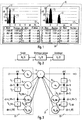
- An expedient representation of the level values found in the semilogarithmic scale in accordance with the representation selected in FIG. 1 requires a logarithmization of the samples of the channel impulse response in the second processing step.
- a level comparison of the individual samples of the channel impulse response is supported.
- An ordered representation of the normalized pulses represents a useful information reduction for the service personnel.
- the individual pulses of the channel impulse response provide echo signals of the individual impurities in A conversion of the temporal positions (in microseconds) of the pulses in corresponding lengths - by multiplying the calculated time with the transmission speed (at radio transmission: speed of light) - therefore facilitates the geographical identification of the obstacles in relation to the position of the mobile measuring device clearly ,
- Claims 15 to 18 relate to a digital storage medium, a computer program or a computer program product for carrying out the method according to the invention.
- the transmitter 1 with the system behavior described by the transfer function H S (f) outputs a signal which is considered ideal.
- This transmitted signal is transmitted via a transmission channel 2 (radio, cable, air, water, etc.).
- the transmission behavior of the transmission channel 2 is described by the transfer function H K (f).
- the transmitted signal is received by the receiver 3 having the transfer function H E (f).
- the receiver 3 includes, inter alia, an equalizer 21 (equalizer), which equalizes the linearly distorted transmission signal from the transmission channel 2.
- the input signal of the non-recursive filter component 22 is the signal x (n) received at the sampling time index n, which is supplied to a first delay element 5 1 .
- the delay element 5 1 delays the signal x (n) by one sampling period T and thus generates the signal x (n-1).
- This signal x (n-1) is delayed by further in-line delay elements, which have identical delay behavior as the first delay element 5 1 , by one sampling period (or symbol duration) T.
- the number of chain-connected delay elements of the FIR filter component corresponds to the order k_FIR of the FIR filter component.
- the chain of delay elements in the FIR filter component 22 thus continues after the delay element 5 1 with the delay element 5 2 and ends with the delay element 5 k_FIR .
- the input signal of the last delay element is consequently the received signal x (n-k_FIR + 1) at the sampling time with the index n-k_FIR + 1, while the associated output signal is the received signal x (n-k_FIR) at the sampling time with the index n-k_FIR.
- the received signal x (n) is supplied to the summation element 4 after multiplication by the coefficient b 0 in the multiplier 6 0 .
- the delayed received signals x (n-1) to x (n-k_FIR) generated in the individual delay elements 5 1 to 5 k_FIR are multiplicatively combined and supplied to the summation element 4.
- the delayed received signal x (n-1) generated by the delay element 5 1 is consequently supplied to the summing element 4 after multiplication by the coefficient b 1 in the multiplier 6 1 .
- the delayed received signal x (n-k_FIR) generated by the delay element 5 k_FIR is consequently supplied to the summation element 4 in the multiplier 6 k_FIR after multiplication by the coefficient b k_FIR .
- the input signal of the recursive filter component 23 is simultaneously the output signal of the equalizer 21 (equalizers) y (n) to the sampling index n and corresponds to the output signal of the summation element 4.
- the output signal y (n) of the equalizer (equalizer ) to the sampling index n a first delay element 7 1 fed.
- This delay element 7 1 which has the same delay characteristic as the delay elements 5 1 to 5 k_IIR of the non-recursive filter component 22, produces an output signal y (n-1) delayed by one sampling period from the output signal y (n).
- This single-delayed output signal y (n-1) is delayed by another chain-connected delay elements having the same delay behavior as the delay element 7 1 , each delayed by one sampling period.
- the number of chain-connected delay elements of the IIR filter component corresponds to the order k_IIR of the IIR filter component.
- the chain of delay elements in the IIR filter component is thus placed after the delay element 7 1 with the Delay 7 2 continues and ends with the delay 7 k_IIR .
- the input signal of the last delay element is consequently the receive signal x (n-k_IIR + 1) to the sampling index n-k_IIR + 1, while the associated output signal is the receive signal x (n-k_IIR) to the sampling index n-k_IIR.
- the simply delayed output signal y (n-1) generated in the delay element 7 1 is supplied to the summation element 4 after multiplication by the coefficient -a 1 in the multiplier 8 1 .
- the delayed output signals y (n-2) to y (n-k_IIR) generated by the remaining delay songs 7 2 to 7 k_IIR are multiplicatively combined and supplied to the summation element 4.
- the k_IIR-1-fold delayed output signal y (n-k_IIR + 1) generated by the delay element 7 K_IIR-1 of the recursive filter component 23 is therefore supplied to the summing element 4 after multiplication by the coefficient -a k_IIR-1 in the multiplier 8 k_IIR-1 .
- the k_IIR-fold delayed output signal y (n-k_IIR) generated by the delay element 7 K_IIR of the recursive filter component 23 is consequently supplied to the summing element 4 after multiplication by the coefficient -a k_IIR in the multiplier 8 k_IIR .
- the FIR component 22 has a transmission behavior with a finite-length impulse response.
- the FIR component 22 is used primarily to compensate for pre-echoes.
- the IIR component 23 has a transmission behavior with an infinitely long impulse response and is therefore particularly suitable for the compensation of post-echoes.
- the coefficients b 0 to b k_FIR and -a 1 to -a k_IIR of the multipliers 6 0 to 6 k_FIR and 8 1 to 8 k_IIR are adjusted via adaptive optimization methods in such a way that the transmission behavior of the equalizer (ideally equalizer) is exactly inverse to the transmission behavior of the Transmission channel 2 is.
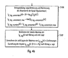
- FIGS. 4a and 4b show an overview of the method according to the invention.
- the determination of the filter coefficients of the equalizer a 1 to a k_IIR and b 0 to b k_FIR represents a first method step S100 upstream of the actual invention in the method sequence for determining the channel impulse response according to FIG. 4.
- the ascertainment of the filter coefficients becomes, as already stated above mentioned, by an adaptive optimization algorithm, for example, according to KD Kammeyer, supra., Performed.
- the input vector A (n) for the calculation of the counter-side, discrete Fourier spectra A '(n) and the input vector B (n) are used as a preparation for calculating the discrete Fourier spectra of the transmission channel by means of discrete Fourier transformation the calculation of the nominator-side, discrete Fourier spectra B '(n) pre-assigned.
- the two input vectors A (n) and B (n) are provided, both of which have the length N F.
- N F is the number of samples in both the time and frequency domain of the Fourier transform, and reasonably should be greater than the maximum of coefficient number of the FIR component k_FIR and IIR component k_IIR of the equalizer (equalizer).
- the assignment of the input vectors A (n) and B (n) is based on the prerequisites already mentioned in the introduction for applying the discrete Fourier transformation to the filter coefficients a n and b n of the equalizer (equalizer) instead of a discrete time function.
- step S102 the output vector A '(n), which corresponds to the counter-side discrete Fourier spectra of the transfer function of the transmission channel H K (f), is calculated from the input vector A (n) according to the formula (5) by means of discrete Fourier transformation.
- the discrete Fourier spectra of the transmission channel H K (f) are obtained by dividing the elements of the counter-side output vector A '(n) by the elements of the detector-side output vector B' (n) according to the formula (7).
- H k ( n ) A ' ( n ) / B ' ( n )
- For 0 ⁇ n ⁇ N F
- undesired deviations of the spectrum from the desired ideal profile occur when the temporal limits of the samples in the time domain are limited by means of a window function.
- the discrete Fourier spectra of the transmission channel H K (n) are preferably weighted with an optimized window function F (n) whose shape is matched to the modulation signal used.
- the determination of the window function F (n) is content of the process step S103.
- the length of the window function vector F (n) of length N F of the discrete Fourier vector of the Transmission channel spectrum H K (n) correspond.
- F (n) 0 for 0 ⁇ n ⁇ n 1
- F (n) 0 for n 2 ⁇ n ⁇ N
- F F (n) ⁇ 0 for n 1 ⁇ n ⁇ n 2
- n 1 and n 2 of the window function F (n) are dependent on the modulation of the signal to be transmitted, since the modulation type the position and width of the discrete Fourier spectrum of the carrier and the useful signal existing, not yet demodulated in the receiver 3 transmission signal determined in the frequency domain.
- n 1 and n 2 different mathematical functions can be used.
- a window function F (n) corresponding to the formula (8) is preferably used.
- F ( n ) a - b ⁇ cos ( 2 ⁇ ⁇ n - n 1 n 2 - n 1 ) + c ⁇ cos ( 4 ⁇ ⁇ n - n 1 n 2 - n 1 )
- the form of the window function F (n) can still be adapted to the specific application or operation.
- the discrete Fourier spectra of the transmission channel H K (n) determined in method step S102 are weighted with the window function by means of multiplication in accordance with the formula (9) in order to minimize the leakage and picket fence effects.
- step S106 the complex fundamental values of the channel impulse response I K (n) therefor are subjected to a magnitude formation in a first sub-step.
- the support values of the channel impulse response I K (n) whose level can scatter over several decades, are still logarithmized in terms of a meaningful representation on a semilogarithmic scale.
- the magnitude formation and logarithmization of the discrete channel impulse response I K (n) is performed according to formula (11).
- I K . log . unnormiert ( n ) 20 * log 10 (
- ) For 0 ⁇ n ⁇ N F
- the next method step S107 therefore includes the search for local maxima of the normalized fundamental values of the channel impulse response I K (n).
- the method according to the invention for searching the local maxima of the channel impulse response I K (n) and for sorting the maxima found according to the magnitude of their magnitude is shown in FIG. 5 and will be explained in detail in a later section of the description.
- the graphic representation in FIG. 1 contains the graphical representation of the channel impulse response I K (n) in the graphical region 10 and the tabular list 20 of, for example, the ten largest magnitudes of the channel impulse response I K (n).
- the graphic area 10 contains a semilogarithmic diagram with the ordinate axis 11, which has a logarithmic scale with the unit dB and is the reference axis of the level value of the nodes of the channel impulse response I K (n), and the abscissa axis 12, which is a linear scale with the unit ⁇ s and reference axis of the temporal position of the vertices of the channel impulse response I K (n).
- the individual interpolation points of the channel impulse response I K (n) are positioned as level columns 13 whose heights correspond to the level values of the interpolation points at the location of the abscissa axis 12 which corresponds to their temporal position.
- the ten highest magnitudes of the channel impulse response I K (n) are listed in descending order with respect to their magnitude value in a three-column table, where the first column is the ranking, the second column is the magnitude of the level value and the third column the temporal position of the base of the channel impulse response I K (n) contains.
- the sub-method for searching a local maximum of the interpolation points of the channel impulse response I K (n), which is shown in FIG. 5, mentioned above in method step S107, begins in method step S110 with the calculation of the first derivative I K '(n) of the discrete interpolation sequence I K (n) of the channel impulse response according to the formula (14).
- the second derivative I K "(n) of the discrete point sequence I K (n) of the channel impulse response is calculated according to the formula.
- I K . log " ( n ) I K . log ' ( n + 1 ) - I K . log ' ( n )
- the query is whether the run variable n is smaller than N F - 2 is, a query, if not all bases have been examined regarding the search for a local maximum.
- the local maxima of the points I K (n) of the channel impulse response found in the search method are sorted with the amount max_I (n) and the temporal position max_n (n) corresponding to the magnitude of the amount max_I (n) ,
- the query is with the further query whether the first derivative I ' K, log (n) of the interpolation sequence between the sampling times n and n + 1 is equal to zero and at the same time the second derivative I'' K, log (n ) of the interpolation point sequence at the sampling instant n + 1 is less than zero, determines whether there is a local maximum between the two sampling instants n and n + 1.
- the next element of the vector max_I (number) for the amounts of the found local maxima is occupied by the amount of the support point I K (n) according to formula (16).
- Max _ I ( number ) I K . log ( n )
- the run variable n for the interpolation points of the channel impulse response I K (n) is incremented for examination of the next interpolation point and branched back to the input of the first interrogation.
- the temporal resolution of the local maxima of the intersections of the channel impulse response I K (n) can be significantly increased if the local maximum is not exactly in the middle between two sampling points n and n + 1 lies.
- the method is one possible solution for increasing the temporal resolution.
- the samples of the first derivative I K '(n) are approximated by a linear polygon whose zero crossing represents the exact location of the local maximum.
- Higher temporal resolution in the interpolation can be achieved by using higher-order functions (eg, spline functions or parabolic pieces).
Landscapes
- Engineering & Computer Science (AREA)
- Power Engineering (AREA)
- Computer Networks & Wireless Communication (AREA)
- Signal Processing (AREA)
- Cable Transmission Systems, Equalization Of Radio And Reduction Of Echo (AREA)
- Filters That Use Time-Delay Elements (AREA)
Claims (15)
- Procédé pour l'identification d'obstacles dans un canal de transmission au moyen de mesure de la durée de parcours par l'analyse de la réponse en impulsion de canal (IK(n)) du canal de transmission (2) moyennant l'utilisation d'un correcteur adaptatif (21) discret en temps, qui est monté en aval du canal de transmission (2) et corrige ce dernier, avec les étapes de procédé suivantes:- Détermination (S100) des coefficients de filtrage IIR (an) d'un composant de filtrage récursif (23) et des coefficients de filtrage FIR (bn) d'un composant de filtrage non récursif (22) du correcteur (21) adaptatif discret en temps,- Occupation (S101) d'un premier vecteur d'entrée (A(n)) initialisé par des zéros avec les coefficients de filtrage IIR (an) correspondant à l'indice et d'un deuxième vecteur d'entrée (B(n)) initialisé par des zéros avec les coefficients de filtrage FIR (bn) correspondant à l'indice, sachant que le premier élément de vecteur (A(0)) du premier vecteur d'entrée (A(n)) est occupé par la valeur 1,- Détermination (S102) d'un premier vecteur de sortie (A' (n)) à partir du premier vecteur d'entrée (A(n)) et d'un deuxième vecteur de sortie (B' (n)) à partir du deuxième vecteur d'entrée (B(n)), chaque fois moyennant l'utilisation de la transformation de Fourier discrète,- Formation (S102) de la fonction discrète de transmission du canal (HK(n)) par division du premier vecteur de sortie (A'(n)) par le deuxième vecteur de sortie (B'(n)) et- Détermination (S105) de la réponse impulsionnelle du canal (IK(n)) à partir de la fonction discrète de transmission du canal (HK(n)) moyennant l'utilisation de la transformation de Fourier discrète inverse,- Détermination (S107) des maxima locaux de la réponse impulsionnelle du canal (IK (n)) d'après la position chronologique et- Conversion des positions chronologiques des maxima locaux en les éloignements correspondants des obstacles par rapport à la position d'un récepteur de mesure contenant le correcteur (21), par multiplication par la vitesse de transmission.
- Procédé selon la revendication 1,
caractérisé en ce que
le premier vecteur de sortie A'(n) est formé par une transformation de Fourier discrète du premier vecteur d'entrée A(n) occupé par les coefficients de filtrage IIR, par la formule
en ce que le deuxième vecteur de sortie B'(n) est formé par une transformation de Fourier discrète du deuxième vecteur d'entrée B(n) occupé par les coefficients de filtrage FIR, par la formule
et en ce que la fonction de transmission du canal HK(n) est formée conformément à la formule
dans lesquellesNF signifie le nombre de valeurs de lecture pour la transformation de Fourier discrète,n signifie l'indice qui détermine les valeurs de référence des vecteurs de sortie etk signifie l'indice qui détermine les valeurs de référence des vecteurs d'entrée. - Procédé selon la revendication 1 ou 2,
caractérisé en ce que
la réponse impulsionnelle complexe du canal IK(n) est formée conformément à la formule
dans laquelleHK(n) signifie la fonction de transmission du canal,NF signifie le nombre de valeurs de lecture pour la transformation de Fourier discrète,k signifie les valeurs discrètes de fréquence etn signifie l'indice qui détermine les valeurs de lecture de la réponse impulsionnelle du canal. - Procédé selon l'une des revendications 1 à 3,
caractérisé en ce que
après la détermination (S105) de la réponse impulsionnelle du canal (IK(n)) suivent comme étapes du procédé la formation de la valeur absolue, la formation du logarithme et la normalisation (S106) de la réponse impulsionnelle du canal IK(n). - Procédé selon la revendication 4,
caractérisé en ce que
la formation de la valeur absolue et la formation du logarithme de la réponse impulsionnelle complexe du canal IK(n) sont formées conformément à la formule
- Procédé selon la revendication 5,
caractérisé en ce que
la normalisation des valeurs impulsionnelles discrètes du canal IK(n) est formée par la recherche de la valeur de lecture la plus grande en valeur absolue IK,log,unnormiert,max(n) conformément à la fonction suivante IK,log,unnormiert,max(n) = max{IK,log,unnormiert (n)} suivie du calcul conformément à la formule
- Procédé selon l'une des revendications 1 à 6,
caractérisé en ce que
avant la détermination (S105) de la réponse impulsionnelle du canal IK(n), une pondération (S104) de la fonction de transmission du canal HK(n) s'effectue avec une fonction de fenêtre F(n) pour l'obtention d'une fonction de transmission du canal HK'(n) limitée en bande de fréquence conformément à la formule
- Procédé selon la revendication 7,
caractérisé en ce que
comme fonction de fenêtre F(n), on choisit la fonctionF(n) = 0 pour 0 <= n < n1 F(n) = 0 pour n2 < n < NF F(n) ≠ 0 pour n1 <= n <= n2 n signifie l'indice discret de la fréquence,NF signifie le nombre des valeurs de lecture pour la transformation de Fourier discrète,n1 signifie la fréquence limite inférieure de la fonction de fenêtre, dépendant du genre de modulation du signal à transmettren2 signifie la fréquence limite supérieure de la fonction de fenêtre, dépendant du genre de modulation du signal à transmettre. - Procédé selon la revendication 8,
caractérisé en ce que
la fonction de fenêtre F(n) est formée conformément à la formule
dans laquellen signifie la valeur discrète de la fréquence,a, b, c, signifient des paramètres pouvant être choisis librement pour la détermination de la forme de la fonction de fenêtre,n1 signifie la fréquence limite inférieure de la fonction de fenêtre, dépendant du genre de modulation du signal à transmettre etn2 signifie la fréquence limite supérieure de la fonction de fenêtre, dépendant du genre de modulation du signal à transmettre. - Procédé selon l'une des revendications 4 à 6,
caractérisé en ce que
après la formation de la valeur absolue, la formation du logarithme et la normalisation (S106) de la réponse impulsionnelle du canal (IK(n)), il suit une détermination (S107) des maxima locaux des valeurs de lecture normalisées de la réponse impulsionnelle du canal (IK(n)) d'après la valeur absolue. - Procédé selon la revendication 10,
caractérisé en ce que
la détermination (107) des maxima locaux des valeurs de lecture normalisées de la réponse impulsionnelle du canal (IK(n)) comprend les étapes de procédé suivantes:- Formation (S110) de la première dérivée (IK,log' (n)) des valeurs discrètes de la réponse impulsionnelle du canal (IK(n)),- Formation (S111) de la deuxième dérivée (IK,log''(n)) des valeurs discrètes de la réponse impulsionnelle du canal (IK(n)),- Détermination de la valeur absolue (max_I(anzahl)) (S112) et de la position chronologique (max_n(anzahl)) (S113) du maximum local, si la première dérivée est nulle et que la deuxième dérivée est négative,- Détermination de la position chronologique exacte (max_n(anzahl)) (S114) du maximum local par interpolation linéaire de la première dérivée au moyen de trois valeurs discrètes (IK,log (n), IK,log(n+1), IK, log(n+2)) ainsi que de la valeur absolue correspondante (max_I(anzahl)) (S115) du maximum local, si le produit des premières dérivées en deux points de référence voisins (n, n+1) et la deuxième dérivée sont négatifs, et- Classement (S116) des valeurs absolues (max_I(anzahl)) et des positions chronologiques (max_n(anzahl)) des maxima locaux trouvés, quand le processus de recherche est terminé. - Procédé selon la revendication 11,
caractérisé en ce que
après la détermination des maxima locaux de la réponse impulsionnelle du canal (IK(n)) et la conversion des positions chronologiques en éloignements correspondant à ces dernières, il s'effectue une représentation des différentes valeurs discrètes des points de référence de la réponse impulsionnelle du canal (IK(n)) et des maxima locaux de la réponse impulsionnelle du canal (IK(n)) sous forme graphique et/ou de tableau. - Support de données numériques avec des signaux de commande, lisibles électroniquement, qui interagissent avec un ordinateur ou un processeur numérique de signaux programmable de telle sorte que le procédé, selon l'une des revendications 1 à 12, soit exécuté.
- Produit de programme pour ordinateur avec des moyens de code de programme enregistrés sur un support exploitable par une machine, pour exécuter toutes les étapes, selon l'une des revendications 1 à 12, quand le programme est exécuté sur un ordinateur ou un processeur de signaux numérique.
- Programme pour ordinateur avec des moyens de code de programme pour pouvoir exécuter toutes les étapes, selon l'une des revendications 1 à 12, quand le programme est exécuté sur un ordinateur ou un processeur de signaux numérique.
Applications Claiming Priority (3)
| Application Number | Priority Date | Filing Date | Title |
|---|---|---|---|
| DE10256452 | 2002-12-03 | ||
| DE10256452A DE10256452A1 (de) | 2002-12-03 | 2002-12-03 | Verfahren zur Analyse der Kanalimpulsantwort eines Übertragungskanals |
| PCT/EP2003/012655 WO2004051865A2 (fr) | 2002-12-03 | 2003-11-12 | Procede d'analyse de la reponse impulsionnelle d'un canal de transmission |
Publications (2)
| Publication Number | Publication Date |
|---|---|
| EP1568186A2 EP1568186A2 (fr) | 2005-08-31 |
| EP1568186B1 true EP1568186B1 (fr) | 2006-05-03 |
Family
ID=32335923
Family Applications (1)
| Application Number | Title | Priority Date | Filing Date |
|---|---|---|---|
| EP03767534A Expired - Lifetime EP1568186B1 (fr) | 2002-12-03 | 2003-11-12 | Procede d'analyse de la reponse impulsionnelle d'un canal de transmission |
Country Status (7)
| Country | Link |
|---|---|
| US (1) | US7630432B2 (fr) |
| EP (1) | EP1568186B1 (fr) |
| JP (1) | JP2006509387A (fr) |
| CN (1) | CN100525264C (fr) |
| AU (1) | AU2003292011A1 (fr) |
| DE (2) | DE10256452A1 (fr) |
| WO (1) | WO2004051865A2 (fr) |
Families Citing this family (15)
| Publication number | Priority date | Publication date | Assignee | Title |
|---|---|---|---|---|
| EP1879292B1 (fr) * | 2006-07-10 | 2013-03-06 | Harman Becker Automotive Systems GmbH | Convolution rapide partitionée |
| US8135140B2 (en) | 2008-11-20 | 2012-03-13 | Harman International Industries, Incorporated | System for active noise control with audio signal compensation |
| US9020158B2 (en) | 2008-11-20 | 2015-04-28 | Harman International Industries, Incorporated | Quiet zone control system |
| US8718289B2 (en) | 2009-01-12 | 2014-05-06 | Harman International Industries, Incorporated | System for active noise control with parallel adaptive filter configuration |
| US8189799B2 (en) | 2009-04-09 | 2012-05-29 | Harman International Industries, Incorporated | System for active noise control based on audio system output |
| US8199924B2 (en) * | 2009-04-17 | 2012-06-12 | Harman International Industries, Incorporated | System for active noise control with an infinite impulse response filter |
| US8611227B2 (en) * | 2009-05-11 | 2013-12-17 | Qualcomm Incorporated | Channel estimate pruning in presence of large signal dynamics in an interference cancellation repeater |
| US9049065B2 (en) * | 2009-05-11 | 2015-06-02 | Qualcomm Incorporated | Removal of ICI/ISI errors in frequency domain channel estimation for wireless repeaters |
| US20110116531A1 (en) * | 2009-05-11 | 2011-05-19 | Qualcomm Incorporated | Removal of multiplicative errors in frequency domain channel estimation for wireless repeaters |
| US8077873B2 (en) | 2009-05-14 | 2011-12-13 | Harman International Industries, Incorporated | System for active noise control with adaptive speaker selection |
| US8582698B2 (en) * | 2010-05-10 | 2013-11-12 | Telefonaktiebolaget Lm Ericsson (Publ) | Reduced complexity timing estimation for locating the position of a mobile terminal |
| TWI524076B (zh) | 2015-02-11 | 2016-03-01 | 瑞昱半導體股份有限公司 | 通道測試方法及其系統 |
| JP6935370B2 (ja) * | 2018-07-24 | 2021-09-15 | アンリツ株式会社 | 信号発生装置および該装置を用いた周波数特性表示方法 |
| US11165462B2 (en) * | 2018-11-07 | 2021-11-02 | Samsung Electronics Co., Ltd. | Motion assisted leakage removal for radar applications |
| CN113794663B (zh) * | 2021-09-09 | 2023-10-10 | 深圳市极致汇仪科技有限公司 | 一种快速找到wifi帧头的fpga实现方法及系统 |
Family Cites Families (8)
| Publication number | Priority date | Publication date | Assignee | Title |
|---|---|---|---|---|
| US4972358A (en) * | 1989-06-08 | 1990-11-20 | General Electric Company | Computation of discrete fourier transform using recursive techniques |
| US5337366A (en) * | 1992-07-07 | 1994-08-09 | Sharp Kabushiki Kaisha | Active control apparatus using adaptive digital filter |
| US5926455A (en) * | 1996-12-19 | 1999-07-20 | Lucent Technologies Inc. | Recursive filters for polyphase structures |
| DE19703060B4 (de) * | 1997-01-28 | 2004-02-26 | Siemens Ag | Verfahren zur Kanalschätzung mit Anpassung eines Kanalmodells während einer Datendetektion |
| US6209014B1 (en) * | 1997-04-14 | 2001-03-27 | Lucent Technologies Inc. | Look-ahead LMS technique |
| DE19858106B4 (de) * | 1998-12-16 | 2014-09-25 | Telefonaktiebolaget Lm Ericsson (Publ) | Empfänger und Verfahren zum Verhindern einer Zwischensymbolstörung in einem Hochgeschwindigkeitsübertragungssystem |
| GB2347054B (en) * | 1999-02-19 | 2003-12-03 | Adaptive Broadband Ltd | Stabilized precoder for data transmission |
| DE10052718A1 (de) * | 2000-10-24 | 2002-05-08 | Siemens Ag | Verfahren zum Bestimmen von Übertragungseigenschaften einer Übertragungsstrecke oder einer Echostrecke sowie zugehörige Empfangseinheiten |
-
2002
- 2002-12-03 DE DE10256452A patent/DE10256452A1/de not_active Withdrawn
-
2003
- 2003-11-12 US US10/541,850 patent/US7630432B2/en not_active Expired - Fee Related
- 2003-11-12 AU AU2003292011A patent/AU2003292011A1/en not_active Abandoned
- 2003-11-12 WO PCT/EP2003/012655 patent/WO2004051865A2/fr not_active Ceased
- 2003-11-12 EP EP03767534A patent/EP1568186B1/fr not_active Expired - Lifetime
- 2003-11-12 CN CNB2003801050671A patent/CN100525264C/zh not_active Expired - Fee Related
- 2003-11-12 JP JP2004556134A patent/JP2006509387A/ja not_active Ceased
- 2003-11-12 DE DE50303253T patent/DE50303253D1/de not_active Expired - Lifetime
Also Published As
| Publication number | Publication date |
|---|---|
| DE50303253D1 (de) | 2006-06-08 |
| WO2004051865A2 (fr) | 2004-06-17 |
| DE10256452A1 (de) | 2004-06-24 |
| CN1720700A (zh) | 2006-01-11 |
| AU2003292011A8 (en) | 2004-06-23 |
| AU2003292011A1 (en) | 2004-06-23 |
| WO2004051865A3 (fr) | 2004-07-29 |
| EP1568186A2 (fr) | 2005-08-31 |
| JP2006509387A (ja) | 2006-03-16 |
| CN100525264C (zh) | 2009-08-05 |
| US20060239385A1 (en) | 2006-10-26 |
| US7630432B2 (en) | 2009-12-08 |
Similar Documents
| Publication | Publication Date | Title |
|---|---|---|
| DE69332975T2 (de) | Digitales filter mit hoher genauigkeit und effizienz | |
| DE60108211T2 (de) | Optimierung von kanalentzerrung | |
| DE69925905T2 (de) | Blinde trennung von quellen durch faltung mit hilfe eines vielfachdekorrelationsverfahrens | |
| DE69529328T2 (de) | Verfahren und Apparat zur Geräuschunterdrückung in einem Sprachsignal und korrespondierendes System mit Echounterdrückung | |
| DE60303214T2 (de) | Verfahren zur reduzierung von aliasing-störungen, die durch die anpassung der spektralen hüllkurve in realwertfilterbanken verursacht werden | |
| DE69518454T2 (de) | Abschätzung von Anregungsparametern | |
| DE69328828T2 (de) | Verfahren und gerät zur analyse von zeitlich veränderlichem frequenzspektrum | |
| DE102005008734B4 (de) | Verfahren und System zur Detektion und/oder Beseitigung von sinusförmigen Störsignalen in einem Rauschsignal | |
| DE10256452A1 (de) | Verfahren zur Analyse der Kanalimpulsantwort eines Übertragungskanals | |
| US20040158592A1 (en) | Method and apparatus for analysis of variables | |
| DE102013217181A1 (de) | Verfahren und System zum Durchführen einer Spektralanalyse eines nicht stationären Signals in Echtzeit | |
| DE2917285A1 (de) | Digitaler spektralanalysator | |
| DE69729373T2 (de) | Verfahren zur berechnung der impulsantwort und empfänger | |
| EP0957471B1 (fr) | Procédé d'évaluation de la qualité de la correction physiologique de signaux audio | |
| DE102011012477A1 (de) | Verfahren zur Bestimmung von Größe und Lage einer Unwucht | |
| DE4317869B4 (de) | System zur Bestimmung einer Instabilität in einem IIR-Filter | |
| DE102005012977B4 (de) | Verfahren und System zur Rauschmessung mit den kombinierbaren Unterverfahren Messen, Identifizieren und Beseitigen von sinusförmigen Störsignalen in einem Rauschsignal | |
| DE60027337T2 (de) | Verfahren und Vorrichtung zum Feststellen von Oberwellen in einem elektrischen Netz | |
| DE19531388C1 (de) | Signaltrennungsverfahren und -einrichtung für nichtlineare Mischungen unbekannter Signale | |
| DE102013224664B4 (de) | Ausgleichsvorrichtung und -verfahren | |
| EP4187263B1 (fr) | Procédé de détermination de phase d'un signal de courant ou de tension | |
| EP0992886B1 (fr) | Procédé et dispositif de détermination de l'énergie d'un signal | |
| DE69626088T2 (de) | Bestimmung der Linienspektrumfrequenzen zur Verwendung in einem Funkfernsprecher | |
| EP0903899A2 (fr) | Procédé et dispositif d'évaluation des signaux de tonalités multifréquences utilisant un filtre d'ondes numérique adaptatif à réjection | |
| EP1993219B1 (fr) | Procédé de calcul de vecteurs d'orientation améliorés |
Legal Events
| Date | Code | Title | Description |
|---|---|---|---|
| PUAI | Public reference made under article 153(3) epc to a published international application that has entered the european phase |
Free format text: ORIGINAL CODE: 0009012 |
|
| 17P | Request for examination filed |
Effective date: 20050406 |
|
| AK | Designated contracting states |
Kind code of ref document: A2 Designated state(s): AT BE BG CH CY CZ DE DK EE ES FI FR GB GR HU IE IT LI LU MC NL PT RO SE SI SK TR |
|
| AX | Request for extension of the european patent |
Extension state: AL LT LV MK |
|
| GRAP | Despatch of communication of intention to grant a patent |
Free format text: ORIGINAL CODE: EPIDOSNIGR1 |
|
| DAX | Request for extension of the european patent (deleted) | ||
| RBV | Designated contracting states (corrected) |
Designated state(s): DE FR GB IT |
|
| GRAS | Grant fee paid |
Free format text: ORIGINAL CODE: EPIDOSNIGR3 |
|
| GRAA | (expected) grant |
Free format text: ORIGINAL CODE: 0009210 |
|
| AK | Designated contracting states |
Kind code of ref document: B1 Designated state(s): DE FR GB IT |
|
| PG25 | Lapsed in a contracting state [announced via postgrant information from national office to epo] |
Ref country code: IT Free format text: LAPSE BECAUSE OF FAILURE TO SUBMIT A TRANSLATION OF THE DESCRIPTION OR TO PAY THE FEE WITHIN THE PRESCRIBED TIME-LIMIT;WARNING: LAPSES OF ITALIAN PATENTS WITH EFFECTIVE DATE BEFORE 2007 MAY HAVE OCCURRED AT ANY TIME BEFORE 2007. THE CORRECT EFFECTIVE DATE MAY BE DIFFERENT FROM THE ONE RECORDED. Effective date: 20060503 |
|
| REG | Reference to a national code |
Ref country code: GB Ref legal event code: FG4D Free format text: NOT ENGLISH |
|
| GBT | Gb: translation of ep patent filed (gb section 77(6)(a)/1977) |
Effective date: 20060504 |
|
| REF | Corresponds to: |
Ref document number: 50303253 Country of ref document: DE Date of ref document: 20060608 Kind code of ref document: P |
|
| ET | Fr: translation filed | ||
| PLBE | No opposition filed within time limit |
Free format text: ORIGINAL CODE: 0009261 |
|
| STAA | Information on the status of an ep patent application or granted ep patent |
Free format text: STATUS: NO OPPOSITION FILED WITHIN TIME LIMIT |
|
| 26N | No opposition filed |
Effective date: 20070206 |
|
| REG | Reference to a national code |
Ref country code: FR Ref legal event code: PLFP Year of fee payment: 13 |
|
| REG | Reference to a national code |
Ref country code: FR Ref legal event code: PLFP Year of fee payment: 14 |
|
| REG | Reference to a national code |
Ref country code: FR Ref legal event code: PLFP Year of fee payment: 15 |
|
| PGFP | Annual fee paid to national office [announced via postgrant information from national office to epo] |
Ref country code: IT Payment date: 20221130 Year of fee payment: 20 Ref country code: GB Payment date: 20221123 Year of fee payment: 20 Ref country code: FR Payment date: 20221121 Year of fee payment: 20 Ref country code: DE Payment date: 20221121 Year of fee payment: 20 |
|
| P01 | Opt-out of the competence of the unified patent court (upc) registered |
Effective date: 20230525 |
|
| REG | Reference to a national code |
Ref country code: DE Ref legal event code: R071 Ref document number: 50303253 Country of ref document: DE |
|
| REG | Reference to a national code |
Ref country code: GB Ref legal event code: PE20 Expiry date: 20231111 |
|
| PG25 | Lapsed in a contracting state [announced via postgrant information from national office to epo] |
Ref country code: GB Free format text: LAPSE BECAUSE OF EXPIRATION OF PROTECTION Effective date: 20231111 |
|
| PG25 | Lapsed in a contracting state [announced via postgrant information from national office to epo] |
Ref country code: GB Free format text: LAPSE BECAUSE OF EXPIRATION OF PROTECTION Effective date: 20231111 |