EP0903899A2 - Procédé et dispositif d'évaluation des signaux de tonalités multifréquences utilisant un filtre d'ondes numérique adaptatif à réjection - Google Patents
Procédé et dispositif d'évaluation des signaux de tonalités multifréquences utilisant un filtre d'ondes numérique adaptatif à réjection Download PDFInfo
- Publication number
- EP0903899A2 EP0903899A2 EP98115498A EP98115498A EP0903899A2 EP 0903899 A2 EP0903899 A2 EP 0903899A2 EP 98115498 A EP98115498 A EP 98115498A EP 98115498 A EP98115498 A EP 98115498A EP 0903899 A2 EP0903899 A2 EP 0903899A2
- Authority
- EP
- European Patent Office
- Prior art keywords
- filter
- pass filtered
- signal
- filtered signal
- wave digital
- Prior art date
- Legal status (The legal status is an assumption and is not a legal conclusion. Google has not performed a legal analysis and makes no representation as to the accuracy of the status listed.)
- Withdrawn
Links
Images


Classifications
-
- H—ELECTRICITY
- H04—ELECTRIC COMMUNICATION TECHNIQUE
- H04L—TRANSMISSION OF DIGITAL INFORMATION, e.g. TELEGRAPHIC COMMUNICATION
- H04L27/00—Modulated-carrier systems
- H04L27/26—Systems using multi-frequency codes
- H04L27/30—Systems using multi-frequency codes wherein each code element is represented by a combination of frequencies
Definitions
- the invention relates to a method for evaluating multi-frequency audio signals in a communication system. Further The invention relates to a device for performing this Procedure.
- Multi-frequency sound signals are used to transmit characters and for signaling in communication systems, e.g. Telephone systems, used to digits or characters over analog To transmit voice channels. Every character is defined by a mixture of two tones by two different tone groups come.
- the use of multi-frequency sound signals in telecommunications systems are described in "Technical Features of Push-Button Telephone Sets ", ITU-T Recommendation Q.23, Blue Book, and "Multifrequency Push-Button Signal Reception", ITU-T Recommendation Q.24, Blue Book.
- a signal is transmitted, which is a mixture of two sound frequencies contains four lower frequencies of a lower Tone group and four tone frequencies of an upper tone group selected are. In this way, a total of 16 different ones Characters can be set.
- tolerances for transmission and reception parameters Are defined.
- the present invention relates to the Reception and evaluation of multi-frequency sound signals.
- the transmitted signal has been evaluated in that it passes bandpass filter banks which contain the sound signals filter out the lower and upper tone groups separately, i.e. there are eight narrow frequency bands on energy content checked. Individual characters are then recognized based on the literature mentioned in the above Conditions. Another known method is based on the signal is the digital Fourier transform according to the Goetzel algorithm applied to the energy content within the narrow frequency bands. With the mentioned procedures according to the state of the art, the required technical Effort relatively large, especially when the sound frequencies fluctuate within increased tolerance ranges.
- a method for evaluating Multi-frequency audio signals specified in a communication system where each character to be transmitted as a signal is shown, which is a mixture of two sound frequencies contains that consists of two different groups of sound frequencies are selected, the digital at a predetermined sampling rate sampled signal fed to a first decimation filter in which the signal is low pass filtered and the sampling rate is reduced by a factor of 2, then the thus filtered signal fed to a second decimation filter which it is while further reducing the sampling rate by a factor of 2 through bandpass filtering to a high-pass filtered Splits signal and a low-pass filtered signal, the high-pass filtered signal to a first adaptive Notch wave digital filter is fed, its adaptive Filter coefficient is a measure of the frequency of the high-pass filtered Signal is the high pass filtered signal after a Sampling rate reduction by a factor of 2 a first level detector is supplied, which the amplitude of the high-pass filtered Signals determined, the low-pass filtered signal third decimation filter
- this is the audio frequency mixture containing transmitted signal through decimation filter and Notch wave digital filter filtered.
- Decimation filter are known digital filters, which the sampling rate decrease by a certain factor. This humiliation the sampling rate is called decimation or Sampling rate reduction.
- the sampling rate reduction by a certain one Number of samples per unit of time is generally realized by hiding samples.
- the present invention is the respective sampling rate reduction 2, i.e. only every second sample is processed.
- the sampling rate reduction always with the addition of a suitable filter adapted to the reduction in sampling rate, e.g. a low pass filter, a band pass filter or a high pass filter. That fed to the decimation filter Signal is initially limited by the adapted filter band, so that at the reduced sampling rate there are no disruptive overlays different frequency components occur what is known as "aliasing".
- a suitable filter adapted to the reduction in sampling rate e.g. a low pass filter, a band pass filter or a high pass filter.
- Digital filter algorithms are preferably used which allow the respective decimation filters with a possible to operate at a low sampling rate.
- non-recursive Filtering algorithms can change the sampling rate by any Factor can be reduced.
- recursive filter algorithms however, this is only possible in exceptional cases. Therefore in one preferred embodiment of the invention as a decimation filter a recursive bi-reciprocal bridge wave digital filter used, which with a sample rate reduction the factor 2 can be operated at the lower sampling rate can.
- the use of recursive filter algorithms requires less technical effort, reducing the overall effort is further reduced for the invention.
- the has called recursive bireziproke bridge wave digital filter the further advantage that complementary filter functions, i.e. Passband and barrier band, without causing additional effort be available. This can advantageously for the separation of the frequency bands for the upper and the lower tone group can be used.
- adaptive notch wave digital filters are used in the invention used, which filter out the respective sound signals.
- Such notch wave digital filters can be digital Realize shape using relatively simple algorithms. By tracking the adaptive filter coefficient and the Evaluation of the filter signal by level detectors can be relative can quickly be determined whether a significant amplitude for a sound signal. Because the adaptive filter coefficient of the adaptive Notch wave digital filter is a measure of the frequency is, the presence can be or not Presence of a certain sound signal.
- a device specified for performing the method according to the invention is specified.
- the features of this device are in claim 7 specified.
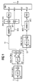
- FIG. 1 schematically shows the structure of the multi-frequency audio signal receiver, which roughly in three processing stages can be classified.
- a first stage contains decimation filters D0 and D1.
- the supplied multi-frequency sound signal S in an upper frequency range HG and a lower frequency range LG.
- the second processing level determined by using Notch wave digital filters ANWDF1 and ANWDF2 as well as level detectors PD1 and PD2 the frequency of the sound signal in the upper frequency range HG or in the lower frequency range LG and the associated Amplitude.
- a third stage of processing includes one Discriminator unit Rw, which from the determined amplitudes and frequencies the transmitted character recognizes and outputs.
- the decimation filter D0 becomes the multi-frequency audio signal S supplied as a digital signal, which is usually was sampled with a sampling frequency of 8 kHz is. For reasons of simplification, the required ones are shown in FIG Hardware such as A / D converter, signal processor, Memory etc. omitted.
- the decimation filter contains D0 a low pass filter DF0 and performs sample data reduction by a factor of 2, i.e. the one output by the decimation filter D0 digital signal sequence has a sampling rate of 4 kHz.
- the decimation filter D0 and the other decimation filters D1 and D2 are recursive bi-reciprocal bridge wave digital filters, their structure are described in "Wave Digital Filters: Theory and Practice ", A. Fettweis, Proceedings of the IEEE, Feb. 1986, pp. 270-327, hereinafter referred to as literature 1, and in "Explicit Formulas for Lattice Wave Digital Filters", L. Gazsi, IEEE Trans. On Circuits and Systems, Jan. 1985, pp. 68-88, hereinafter referred to as literature 2.
- Such decimation filters are reduced by a factor of 2 operated in the lower sampling rate. You have a recursive Filter algorithm, which increases the technical effort diminished in the implementation.
- the signal S filtered by the decimation filter becomes the second decimation filter D1, which is a bandpass filter DF1 contains.
- the bandpass filter DF1 is under Exploitation of the decimation filter without such Additional effort available complementary filter function that Signal S into a high-pass filtered signal S1 and a low-pass filtered Split signal S2.
- the decimation filter D1 a further reduction in the sampling rate by a factor of 2 carried out, i.e. the signals S1 and S2 are at a sampling rate now has 2 kHz.
- the decimation filters D0 and D1 also becomes audible suppression at 425 Hz performed to interfere with this audible tone on the Avoid signals S1 and S2.
- the high-frequency signal S1 is in the second processing stage the adaptive Notch wave digital filter ANWDF1 fed.
- This ANWDF1 notch wave digital filter becomes Isolation of a sinusoidal useful signal from the signal S1 used.
- An advantageous property of this Notch wave digital filter is the simple, independent parameterization the center frequency and the bandwidth of the transfer function. Furthermore, such a filter has very good numerical ones Properties and is therefore relatively easy to implement.
- the structure of Notch wave digital filters is e.g. described in the article "Adaptive Notch Wave Digital Filters ", A. Zalnieriunas, Proceedings of ISCAS, New Orleans, USA, May 1990, in the following literature 3.
- the one at this Embodiment used Notch wave digital filter ANWDF1 and ANWDF2 are second as bridge wave digital filters Degrees with a fixed filter coefficient and an adaptive Filter coefficients k1 and k2 executed.
- the Notch wave digital filter ANWDF1 has a bandstop output BS1 and a complementary bandpass output BP1.
- the bandstop output BS1 is used for adaptation of the Notch wave digital filter ANWDF1, i.e. for adjustment of the frequency response.
- the adaptive filter coefficient k1 is via this output BS1 set by the signal processor. In the latter Literature is explained in detail how the Center frequency and the bandwidth of the Notch wave digital filter ANWDF1 through the fixed filter coefficient and the adaptive Filter coefficient k1 is defined.
- the parameter k1 and thus the center frequency of the Notch wave digital filter ANWDF1 is readjusted until an error signal becomes minimal.
- the center frequency corresponds of the Notch wave digital filter ANWDF1 to be detected Audio frequency.
- the amplitude of this tone frequency is at the output Determine BP1 of the bandpass filter.
- the signal at the output of the Notch wave digital filter is subjected to a further sampling rate reduction, i.e. the Sampling frequency drops from 2 kHz to 1 kKz in the example.
- the Signal is then fed to the level detector PD1, which the Indicates amplitude a1 of the detected sound signal.
- the level detectors PD1 and PD2 can be based on peak detection work because in the case of sinusoidal signals as sound signals the peak value is proportional to the signal energy.
- the downstream discriminator unit Rw based on the Amplitude a1 and the set filter coefficient k1 determines whether there is a sound signal or not.
- the low-pass filtered signal S2 becomes a third decimation filter D2 supplied, which contains a high-pass filter DF2 and performs a scan rate reduction by a factor of 2, i.e. the sampling rate at the output of the decimation filter is D2 only 1 kHz.
- the signal filtered in this way becomes the notch wave digital filter ANWDF2 fed which has a band stop output BS2 and the bandpass output BP2.
- the structure of the The ANWDF2 notch wave digital filter corresponds in principle to that of the Notch wave digital filter ANWDF1, but is at the bottom Sound signal group LG adapted. Also with this Notch wave digital filter ANWDF2 will use the Filter coefficient k2 set.
- the amplitude at the output BP2 is determined using the level detector PD2. Also in this case, the discriminator unit Rw uses the Filter coefficients k2 and the amplitude a2 determines whether a sound signal is present in the lower tone signal group LG or Not. By linking the sound signals from the upper sound signal group and the determined audio signals of the lower audio signal group the discriminator unit determines that in the multi-frequency audio signal contained characters and gives this to a higher-level control.
- Figure 2 shows the signals according to the different in diagrams Decimation filters, the signal amplitudes of the audible tone HT, the sound signals of the lower sound signal group LG and the sound signals of the upper sound signal group HG over the frequency are applied.
- the diagram in the middle of the figure 2 shows the low-pass filtered signal S2 after passing through the third decimation filter D2, i.e. at a sampling rate of 1 kHz.
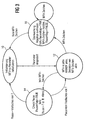
- FIG. 3 shows the evaluation of the amplitudes a1 and a2 and the information contained in the filter coefficients k1 and k2 to determine a character based on a representation as a state machine.
- Initialization takes place in state 10 in the signal processor for multi-frequency audio signal evaluation.
- the State 12 activates the multi-frequency audio signal evaluation and multifrequency sound signals are detected. If no multi-frequency sound signal is present, it is checked in state 14 whether a pause is greater than a predetermined time T, e.g. greater 40 ms, is present. This information is saved. If there is a multiple of this pause, it becomes a state 10 branches. Otherwise, status 12 is returned.
- T e.g. greater 40 ms
- State 16 is set when a valid multi-frequency audio signal was determined. In this state it will End of the valid tone signal determined. If this is the case occurs, the system branches to state 10. The recognized sound signal is only released as valid in state 16 if a sufficiently long pause was previously detected (cf. state 14) has been.
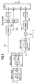
- Figures 4 to 6 show further embodiments of the Invention that allow a largely multiplication-free Implement arrangement with further reduced effort. These embodiments are particularly for using binary fixed-point arithmetic and one Word length of 12 bits suitable. The relatively short word length is achieved by optimally scaling the signals in the receiver reached. With the adaptive notch wave digital filters "Adaptive" scaling has been implemented especially for this.
- a receiver is shown, which is only slightly from which differs according to Figure 1.
- the difference is that a negation element before the second notch wave digital filter ANWDF2 M is arranged.
- This negating member M negates everyone second value of the incoming digital signal sequence, such as this is shown in Figure 4 in brackets.
- a band reversal is achieved by this measure, whereby the convergence properties of that shown in Figure 6 and later explained adaptation algorithm improve which realized by the second Notch wave digital filter ANWDF2 is.
- the decimation filters DF0, DF1 and DF2 used are preferably implemented as proposed in literature 2.
- the calculation of the filter coefficients ⁇ N for filter Nth degree is described there.
- the second decimation filter DF2 is implemented as a recursive three-level bire-reciprocal bridge wave digital filter with the non-zero coefficient ⁇ 1.
- the audible frequency is known to be country-specific.
- the adaptive notch wave digital filters ANWDF1 and ANWDF2 are preferably second degree filters with a fixed Coefficient and an adaptive coefficient. These filters are characterized by the direct assignment between the detecting frequency and the adaptive coefficient k1 and from.
- the fixed coefficients are used for the Notch wave digital filters ANWDF1 and ANWDF2 set to zero. This reduces the implementation effort, in particular the number of arithmetic blocks is reduced.
- Notch wave digital filters are in the literature 3 described in detail. Usually contains one Notch wave digital filter two arithmetic blocks with adapter functions. In the present embodiment 6, however, is only a single arithmetic block used. The implementation effort is thereby significantly reduced and the scaling of the signals is above that easy to design. The scaling is done in Dependence of the variable coefficient and is therefore also to be called "adaptive". This scaling is valid for the entire stable range of values of the variable coefficient and also guarantees the constant transition of the Filter transfer function with constant change of the adaptive Coefficients. The adaptation of the variable coefficients is carried out using a gradient sign algorithm.
- T means the delay by one sampling period, k the adaptive coefficient, s the sign of the adaptive Coefficients k, -s the negated sign of the adaptive Coefficients k, + an addition, x a multiplication, and sign the determination of the sign.
- the signal sequence arriving at the input is first multiplied by the shift factor 2 -1 and then distributed at node 20, namely to a delay element 21, a summing element 22 and with the opposite sign to a summing element 24, on which the output signal is formed, either the output signal BP1 or the output signal BP2 (see FIG. 4).
- the signal generated by delay element 21 arrives at arithmetic block 26, the structure of which is described, for example, in literature 1, table 10, version D.
- the present embodiment differs from this a conditional sign reversal of two signal values added been.
- the respective signal sign is reversed with a negative value of s or -s.
- the result at the multiplier 32 with the Multiplied coefficient k is the summers 34, 36, the latter with conditional sign reversal, supplied, which also the output signal of the delay element 21 or the output signal of the delay element 30 receive.
- the output signal of the summing element 34 forms that Input signal for the delay element 30.
- the output signal of the summing element 36 branches onto the summing element 22 and the summing element 24.
- the result at the summing element 28 is fed to the summing element 38 after multiplication by the shift factor 2 -1 , the output signal of which is supplied to the delay element 40 and to the summing element 42, the latter with conditional sign reversal.
- the output signal of the delay element 40 is fed to the summing element 42 and the multiplier 50.
- the result from the multiplier 50 is in turn fed to the summing element 38.
- the output signal of the summing element 42 is the gradient from the notch wave digital filter based on the coefficient k.
- the sign is determined in block "sign", which serves as an input variable for multiplication element 44, to which the result of summing element 22 is also fed.
- the result of the multiplier 44 is a Scaling factor u applied and then after sign reversal fed to the summing element 46.
- the scaling factor u determines the rate of convergence of the adaptation.
- This scaling factor u is preferably called a power set by 2 and can, if necessary, either through the output of the level detector PD or directly above the gradient controlled, adjusted. This is particularly useful when receiving short multi-frequency sound signals with a signal duration of 40 ms is required.
- the scaling factor u should be inversely proportional in this case be selected for the control signal.
- the result of the summing element 46 reaches the delay element 48, whose output signal in turn to the summing element 46 is returned.
- the output signal of the delay element 48 is then the adaptation coefficient k, which is the input variable the multiplication elements 32 and 50 is supplied.
- the Notch wave digital filter only one arithmetic block 26, a gradient sign algorithm for coefficient adaptation and a "Adaptive" scaling based on conditional sign reversal of the relevant signals.
- a gradient sign algorithm for coefficient adaptation and a "Adaptive" scaling based on conditional sign reversal of the relevant signals As a result, relatively little Multiplications are to be carried out with otherwise the same filter performance.
- the function of the filter described is very good efficient. E.g. with a microprocessor ⁇ C68EC000 with a Clock frequency of 10 MHz was within a time window of 2 ms in length, a processor load of only 11.3% detected.
- a comparison with a common Goertzel algorithm, as suggested in literature 3 processor load of 36.8% is otherwise the same Boundary conditions. This means that the one proposed here
- the microprocessor filters only a small part is busy and do other tasks at the same time can.
Landscapes
- Engineering & Computer Science (AREA)
- Computer Networks & Wireless Communication (AREA)
- Signal Processing (AREA)
- Compression, Expansion, Code Conversion, And Decoders (AREA)
- Measurement Of Mechanical Vibrations Or Ultrasonic Waves (AREA)
Applications Claiming Priority (2)
| Application Number | Priority Date | Filing Date | Title |
|---|---|---|---|
| DE19740173 | 1997-09-12 | ||
| DE19740173 | 1997-09-12 |
Publications (2)
| Publication Number | Publication Date |
|---|---|
| EP0903899A2 true EP0903899A2 (fr) | 1999-03-24 |
| EP0903899A3 EP0903899A3 (fr) | 2001-08-01 |
Family
ID=7842173
Family Applications (1)
| Application Number | Title | Priority Date | Filing Date |
|---|---|---|---|
| EP98115498A Withdrawn EP0903899A3 (fr) | 1997-09-12 | 1998-08-17 | Procédé et dispositif d'évaluation des signaux de tonalités multifréquences utilisant un filtre d'ondes numérique adaptatif à réjection |
Country Status (1)
| Country | Link |
|---|---|
| EP (1) | EP0903899A3 (fr) |
Cited By (5)
| Publication number | Priority date | Publication date | Assignee | Title |
|---|---|---|---|---|
| WO2001031891A3 (fr) * | 1999-10-28 | 2001-09-20 | Siemens Ag | Procede de traitement d'un signal de transmission sinusoidal |
| WO2001031932A3 (fr) * | 1999-10-28 | 2002-02-07 | Siemens Ag | Procede et dispositif de reception permettant de traiter un signal produit selon le procede de numerotation multifrequence |
| CN102281045A (zh) * | 2011-04-15 | 2011-12-14 | 深圳大学 | 一种构建子带自适应滤波器方法 |
| US20120119754A1 (en) * | 2009-05-19 | 2012-05-17 | Abb Ag | Method and device for insulation monitoring of non-grounded electrical dc and ac grids |
| CN121356579A (zh) * | 2025-12-17 | 2026-01-16 | 深圳市斯帕克电气有限公司 | 基于软件算法的ADC50Hz或60Hz噪声滤除方法 |
Family Cites Families (1)
| Publication number | Priority date | Publication date | Assignee | Title |
|---|---|---|---|---|
| US5392348A (en) * | 1991-11-25 | 1995-02-21 | Motorola, Inc. | DTMF detection having sample rate decimation and adaptive tone detection |
-
1998
- 1998-08-17 EP EP98115498A patent/EP0903899A3/fr not_active Withdrawn
Cited By (7)
| Publication number | Priority date | Publication date | Assignee | Title |
|---|---|---|---|---|
| WO2001031891A3 (fr) * | 1999-10-28 | 2001-09-20 | Siemens Ag | Procede de traitement d'un signal de transmission sinusoidal |
| WO2001031932A3 (fr) * | 1999-10-28 | 2002-02-07 | Siemens Ag | Procede et dispositif de reception permettant de traiter un signal produit selon le procede de numerotation multifrequence |
| US20120119754A1 (en) * | 2009-05-19 | 2012-05-17 | Abb Ag | Method and device for insulation monitoring of non-grounded electrical dc and ac grids |
| US8994379B2 (en) * | 2009-05-19 | 2015-03-31 | Abb Ag | Method and device for insulation monitoring of non-grounded electrical DC and AC grids |
| CN102281045A (zh) * | 2011-04-15 | 2011-12-14 | 深圳大学 | 一种构建子带自适应滤波器方法 |
| WO2012139357A1 (fr) * | 2011-04-15 | 2012-10-18 | 深圳大学 | Procédé destiné à réaliser un filtre auto-adaptatif de sous-bande |
| CN121356579A (zh) * | 2025-12-17 | 2026-01-16 | 深圳市斯帕克电气有限公司 | 基于软件算法的ADC50Hz或60Hz噪声滤除方法 |
Also Published As
| Publication number | Publication date |
|---|---|
| EP0903899A3 (fr) | 2001-08-01 |
Similar Documents
| Publication | Publication Date | Title |
|---|---|---|
| EP0212307B1 (fr) | Récepteur de télécommande centralisé | |
| EP0830771B1 (fr) | Procede et circuit destines a ameliorer la separation des porteuses lors de la transmission de signaux ofdm | |
| EP0290790B1 (fr) | Banc de filtres | |
| DE3541031A1 (de) | Verfahren und vorrichtung zum demodulieren von hochfrequent modulierten signalen mittels digitaler filter und digitaler demodulatoren, sowie anwendung des verfahrens in einem fernsteuerempfaenger | |
| DE69224625T2 (de) | Verfahren zum detektieren eines disable-tonsignals eines echokompensators | |
| DE2558402C3 (de) | Digitaler Mehrfrequenzcodesignalempfänger für Fernmelde-, insbesondere Fernsprechvermittlungsanlagen | |
| DE2917285A1 (de) | Digitaler spektralanalysator | |
| DE2707936C3 (de) | Einseitenband-FrequenzmultiplexÜbertragungssystem | |
| EP0234452B1 (fr) | Circuit numérique pour la conversion de la fréquence d'échantillonnage, le filtrage de signaux et son procédé de développement | |
| DE68907098T2 (de) | Differentieller Kodierer mit auto-adaptivem Prädiktorfilter und dazugehörigem Dekodierer. | |
| EP0105087B1 (fr) | Filtre digital pour récepteur de télécommande | |
| EP0903899A2 (fr) | Procédé et dispositif d'évaluation des signaux de tonalités multifréquences utilisant un filtre d'ondes numérique adaptatif à réjection | |
| EP0901225A2 (fr) | Dispositif de filtrage numérique accordable | |
| DE69628130T2 (de) | Digitales Schmalbandfilter | |
| DE3922469C2 (fr) | ||
| EP0284734B1 (fr) | Circuit pour la reconnaissance de signaux multifréquences à deux tonalités dans des centraux téléphoniques | |
| EP0256286B1 (fr) | Dispositif de filtrage | |
| EP0609707B1 (fr) | Procédé pour la détermination de la fréquence momentanée | |
| EP0599144B1 (fr) | Procédé de génération d'un signal vidéo modifié | |
| EP1515447B1 (fr) | Procédé de suppression de bruit dans un système de traitement de signaux et système de traitement de signaux | |
| DE3831047C2 (fr) | ||
| DE69015193T2 (de) | Schaltung zur audiosignalverarbeitung. | |
| EP0902575A2 (fr) | Procédé et dispositif d'évaluation des signaux de tonalités multifréquences utilisant un filtre d'ondes numérique adaptatif à réjection | |
| DE3418011C2 (fr) | ||
| EP0795959A1 (fr) | Combinaison disymmétrique de filtres pour un système de transmission numérique |
Legal Events
| Date | Code | Title | Description |
|---|---|---|---|
| PUAI | Public reference made under article 153(3) epc to a published international application that has entered the european phase |
Free format text: ORIGINAL CODE: 0009012 |
|
| AK | Designated contracting states |
Kind code of ref document: A2 Designated state(s): DE FR GB IT |
|
| AX | Request for extension of the european patent |
Free format text: AL;LT;LV;MK;RO;SI |
|
| PUAL | Search report despatched |
Free format text: ORIGINAL CODE: 0009013 |
|
| AK | Designated contracting states |
Kind code of ref document: A3 Designated state(s): AT BE CH CY DE DK ES FI FR GB GR IE IT LI LU MC NL PT SE |
|
| AX | Request for extension of the european patent |
Free format text: AL;LT;LV;MK;RO;SI |
|
| 17P | Request for examination filed |
Effective date: 20011217 |
|
| AKX | Designation fees paid |
Free format text: DE FR GB IT |
|
| STAA | Information on the status of an ep patent application or granted ep patent |
Free format text: STATUS: THE APPLICATION IS DEEMED TO BE WITHDRAWN |
|
| 18D | Application deemed to be withdrawn |
Effective date: 20060301 |