EP0903899A2 - Method and apparatus for evaluating Multifrequency tone signals using an adaptive wave digital notch filter - Google Patents
Method and apparatus for evaluating Multifrequency tone signals using an adaptive wave digital notch filter Download PDFInfo
- Publication number
- EP0903899A2 EP0903899A2 EP98115498A EP98115498A EP0903899A2 EP 0903899 A2 EP0903899 A2 EP 0903899A2 EP 98115498 A EP98115498 A EP 98115498A EP 98115498 A EP98115498 A EP 98115498A EP 0903899 A2 EP0903899 A2 EP 0903899A2
- Authority
- EP
- European Patent Office
- Prior art keywords
- filter
- pass filtered
- signal
- filtered signal
- wave digital
- Prior art date
- Legal status (The legal status is an assumption and is not a legal conclusion. Google has not performed a legal analysis and makes no representation as to the accuracy of the status listed.)
- Withdrawn
Links
Images


Classifications
-
- H—ELECTRICITY
- H04—ELECTRIC COMMUNICATION TECHNIQUE
- H04L—TRANSMISSION OF DIGITAL INFORMATION, e.g. TELEGRAPHIC COMMUNICATION
- H04L27/00—Modulated-carrier systems
- H04L27/26—Systems using multi-frequency codes
- H04L27/30—Systems using multi-frequency codes wherein each code element is represented by a combination of frequencies
Definitions
- the invention relates to a method for evaluating multi-frequency audio signals in a communication system. Further The invention relates to a device for performing this Procedure.
- Multi-frequency sound signals are used to transmit characters and for signaling in communication systems, e.g. Telephone systems, used to digits or characters over analog To transmit voice channels. Every character is defined by a mixture of two tones by two different tone groups come.
- the use of multi-frequency sound signals in telecommunications systems are described in "Technical Features of Push-Button Telephone Sets ", ITU-T Recommendation Q.23, Blue Book, and "Multifrequency Push-Button Signal Reception", ITU-T Recommendation Q.24, Blue Book.
- a signal is transmitted, which is a mixture of two sound frequencies contains four lower frequencies of a lower Tone group and four tone frequencies of an upper tone group selected are. In this way, a total of 16 different ones Characters can be set.
- tolerances for transmission and reception parameters Are defined.
- the present invention relates to the Reception and evaluation of multi-frequency sound signals.
- the transmitted signal has been evaluated in that it passes bandpass filter banks which contain the sound signals filter out the lower and upper tone groups separately, i.e. there are eight narrow frequency bands on energy content checked. Individual characters are then recognized based on the literature mentioned in the above Conditions. Another known method is based on the signal is the digital Fourier transform according to the Goetzel algorithm applied to the energy content within the narrow frequency bands. With the mentioned procedures according to the state of the art, the required technical Effort relatively large, especially when the sound frequencies fluctuate within increased tolerance ranges.
- a method for evaluating Multi-frequency audio signals specified in a communication system where each character to be transmitted as a signal is shown, which is a mixture of two sound frequencies contains that consists of two different groups of sound frequencies are selected, the digital at a predetermined sampling rate sampled signal fed to a first decimation filter in which the signal is low pass filtered and the sampling rate is reduced by a factor of 2, then the thus filtered signal fed to a second decimation filter which it is while further reducing the sampling rate by a factor of 2 through bandpass filtering to a high-pass filtered Splits signal and a low-pass filtered signal, the high-pass filtered signal to a first adaptive Notch wave digital filter is fed, its adaptive Filter coefficient is a measure of the frequency of the high-pass filtered Signal is the high pass filtered signal after a Sampling rate reduction by a factor of 2 a first level detector is supplied, which the amplitude of the high-pass filtered Signals determined, the low-pass filtered signal third decimation filter
- this is the audio frequency mixture containing transmitted signal through decimation filter and Notch wave digital filter filtered.
- Decimation filter are known digital filters, which the sampling rate decrease by a certain factor. This humiliation the sampling rate is called decimation or Sampling rate reduction.
- the sampling rate reduction by a certain one Number of samples per unit of time is generally realized by hiding samples.
- the present invention is the respective sampling rate reduction 2, i.e. only every second sample is processed.
- the sampling rate reduction always with the addition of a suitable filter adapted to the reduction in sampling rate, e.g. a low pass filter, a band pass filter or a high pass filter. That fed to the decimation filter Signal is initially limited by the adapted filter band, so that at the reduced sampling rate there are no disruptive overlays different frequency components occur what is known as "aliasing".
- a suitable filter adapted to the reduction in sampling rate e.g. a low pass filter, a band pass filter or a high pass filter.
- Digital filter algorithms are preferably used which allow the respective decimation filters with a possible to operate at a low sampling rate.
- non-recursive Filtering algorithms can change the sampling rate by any Factor can be reduced.
- recursive filter algorithms however, this is only possible in exceptional cases. Therefore in one preferred embodiment of the invention as a decimation filter a recursive bi-reciprocal bridge wave digital filter used, which with a sample rate reduction the factor 2 can be operated at the lower sampling rate can.
- the use of recursive filter algorithms requires less technical effort, reducing the overall effort is further reduced for the invention.
- the has called recursive bireziproke bridge wave digital filter the further advantage that complementary filter functions, i.e. Passband and barrier band, without causing additional effort be available. This can advantageously for the separation of the frequency bands for the upper and the lower tone group can be used.
- adaptive notch wave digital filters are used in the invention used, which filter out the respective sound signals.
- Such notch wave digital filters can be digital Realize shape using relatively simple algorithms. By tracking the adaptive filter coefficient and the Evaluation of the filter signal by level detectors can be relative can quickly be determined whether a significant amplitude for a sound signal. Because the adaptive filter coefficient of the adaptive Notch wave digital filter is a measure of the frequency is, the presence can be or not Presence of a certain sound signal.
- a device specified for performing the method according to the invention is specified.
- the features of this device are in claim 7 specified.
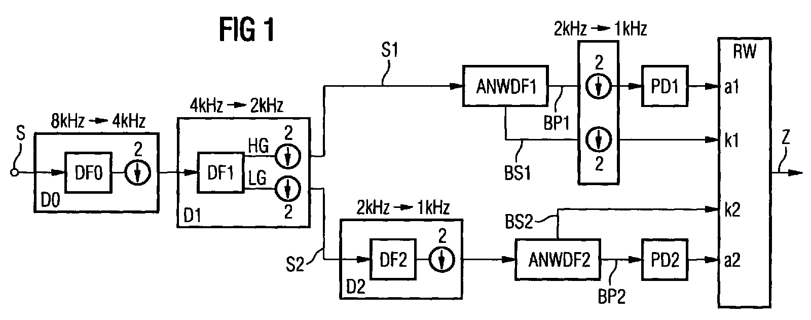
- FIG. 1 schematically shows the structure of the multi-frequency audio signal receiver, which roughly in three processing stages can be classified.
- a first stage contains decimation filters D0 and D1.
- the supplied multi-frequency sound signal S in an upper frequency range HG and a lower frequency range LG.
- the second processing level determined by using Notch wave digital filters ANWDF1 and ANWDF2 as well as level detectors PD1 and PD2 the frequency of the sound signal in the upper frequency range HG or in the lower frequency range LG and the associated Amplitude.
- a third stage of processing includes one Discriminator unit Rw, which from the determined amplitudes and frequencies the transmitted character recognizes and outputs.
- the decimation filter D0 becomes the multi-frequency audio signal S supplied as a digital signal, which is usually was sampled with a sampling frequency of 8 kHz is. For reasons of simplification, the required ones are shown in FIG Hardware such as A / D converter, signal processor, Memory etc. omitted.
- the decimation filter contains D0 a low pass filter DF0 and performs sample data reduction by a factor of 2, i.e. the one output by the decimation filter D0 digital signal sequence has a sampling rate of 4 kHz.
- the decimation filter D0 and the other decimation filters D1 and D2 are recursive bi-reciprocal bridge wave digital filters, their structure are described in "Wave Digital Filters: Theory and Practice ", A. Fettweis, Proceedings of the IEEE, Feb. 1986, pp. 270-327, hereinafter referred to as literature 1, and in "Explicit Formulas for Lattice Wave Digital Filters", L. Gazsi, IEEE Trans. On Circuits and Systems, Jan. 1985, pp. 68-88, hereinafter referred to as literature 2.
- Such decimation filters are reduced by a factor of 2 operated in the lower sampling rate. You have a recursive Filter algorithm, which increases the technical effort diminished in the implementation.
- the signal S filtered by the decimation filter becomes the second decimation filter D1, which is a bandpass filter DF1 contains.
- the bandpass filter DF1 is under Exploitation of the decimation filter without such Additional effort available complementary filter function that Signal S into a high-pass filtered signal S1 and a low-pass filtered Split signal S2.
- the decimation filter D1 a further reduction in the sampling rate by a factor of 2 carried out, i.e. the signals S1 and S2 are at a sampling rate now has 2 kHz.
- the decimation filters D0 and D1 also becomes audible suppression at 425 Hz performed to interfere with this audible tone on the Avoid signals S1 and S2.
- the high-frequency signal S1 is in the second processing stage the adaptive Notch wave digital filter ANWDF1 fed.
- This ANWDF1 notch wave digital filter becomes Isolation of a sinusoidal useful signal from the signal S1 used.
- An advantageous property of this Notch wave digital filter is the simple, independent parameterization the center frequency and the bandwidth of the transfer function. Furthermore, such a filter has very good numerical ones Properties and is therefore relatively easy to implement.
- the structure of Notch wave digital filters is e.g. described in the article "Adaptive Notch Wave Digital Filters ", A. Zalnieriunas, Proceedings of ISCAS, New Orleans, USA, May 1990, in the following literature 3.
- the one at this Embodiment used Notch wave digital filter ANWDF1 and ANWDF2 are second as bridge wave digital filters Degrees with a fixed filter coefficient and an adaptive Filter coefficients k1 and k2 executed.
- the Notch wave digital filter ANWDF1 has a bandstop output BS1 and a complementary bandpass output BP1.
- the bandstop output BS1 is used for adaptation of the Notch wave digital filter ANWDF1, i.e. for adjustment of the frequency response.
- the adaptive filter coefficient k1 is via this output BS1 set by the signal processor. In the latter Literature is explained in detail how the Center frequency and the bandwidth of the Notch wave digital filter ANWDF1 through the fixed filter coefficient and the adaptive Filter coefficient k1 is defined.
- the parameter k1 and thus the center frequency of the Notch wave digital filter ANWDF1 is readjusted until an error signal becomes minimal.
- the center frequency corresponds of the Notch wave digital filter ANWDF1 to be detected Audio frequency.
- the amplitude of this tone frequency is at the output Determine BP1 of the bandpass filter.
- the signal at the output of the Notch wave digital filter is subjected to a further sampling rate reduction, i.e. the Sampling frequency drops from 2 kHz to 1 kKz in the example.
- the Signal is then fed to the level detector PD1, which the Indicates amplitude a1 of the detected sound signal.
- the level detectors PD1 and PD2 can be based on peak detection work because in the case of sinusoidal signals as sound signals the peak value is proportional to the signal energy.
- the downstream discriminator unit Rw based on the Amplitude a1 and the set filter coefficient k1 determines whether there is a sound signal or not.
- the low-pass filtered signal S2 becomes a third decimation filter D2 supplied, which contains a high-pass filter DF2 and performs a scan rate reduction by a factor of 2, i.e. the sampling rate at the output of the decimation filter is D2 only 1 kHz.
- the signal filtered in this way becomes the notch wave digital filter ANWDF2 fed which has a band stop output BS2 and the bandpass output BP2.
- the structure of the The ANWDF2 notch wave digital filter corresponds in principle to that of the Notch wave digital filter ANWDF1, but is at the bottom Sound signal group LG adapted. Also with this Notch wave digital filter ANWDF2 will use the Filter coefficient k2 set.
- the amplitude at the output BP2 is determined using the level detector PD2. Also in this case, the discriminator unit Rw uses the Filter coefficients k2 and the amplitude a2 determines whether a sound signal is present in the lower tone signal group LG or Not. By linking the sound signals from the upper sound signal group and the determined audio signals of the lower audio signal group the discriminator unit determines that in the multi-frequency audio signal contained characters and gives this to a higher-level control.
- Figure 2 shows the signals according to the different in diagrams Decimation filters, the signal amplitudes of the audible tone HT, the sound signals of the lower sound signal group LG and the sound signals of the upper sound signal group HG over the frequency are applied.
- the diagram in the middle of the figure 2 shows the low-pass filtered signal S2 after passing through the third decimation filter D2, i.e. at a sampling rate of 1 kHz.
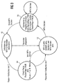
- FIG. 3 shows the evaluation of the amplitudes a1 and a2 and the information contained in the filter coefficients k1 and k2 to determine a character based on a representation as a state machine.
- Initialization takes place in state 10 in the signal processor for multi-frequency audio signal evaluation.
- the State 12 activates the multi-frequency audio signal evaluation and multifrequency sound signals are detected. If no multi-frequency sound signal is present, it is checked in state 14 whether a pause is greater than a predetermined time T, e.g. greater 40 ms, is present. This information is saved. If there is a multiple of this pause, it becomes a state 10 branches. Otherwise, status 12 is returned.
- T e.g. greater 40 ms
- State 16 is set when a valid multi-frequency audio signal was determined. In this state it will End of the valid tone signal determined. If this is the case occurs, the system branches to state 10. The recognized sound signal is only released as valid in state 16 if a sufficiently long pause was previously detected (cf. state 14) has been.
- Figures 4 to 6 show further embodiments of the Invention that allow a largely multiplication-free Implement arrangement with further reduced effort. These embodiments are particularly for using binary fixed-point arithmetic and one Word length of 12 bits suitable. The relatively short word length is achieved by optimally scaling the signals in the receiver reached. With the adaptive notch wave digital filters "Adaptive" scaling has been implemented especially for this.
- a receiver is shown, which is only slightly from which differs according to Figure 1.
- the difference is that a negation element before the second notch wave digital filter ANWDF2 M is arranged.
- This negating member M negates everyone second value of the incoming digital signal sequence, such as this is shown in Figure 4 in brackets.
- a band reversal is achieved by this measure, whereby the convergence properties of that shown in Figure 6 and later explained adaptation algorithm improve which realized by the second Notch wave digital filter ANWDF2 is.
- the decimation filters DF0, DF1 and DF2 used are preferably implemented as proposed in literature 2.
- the calculation of the filter coefficients ⁇ N for filter Nth degree is described there.
- the second decimation filter DF2 is implemented as a recursive three-level bire-reciprocal bridge wave digital filter with the non-zero coefficient ⁇ 1.
- the audible frequency is known to be country-specific.
- the adaptive notch wave digital filters ANWDF1 and ANWDF2 are preferably second degree filters with a fixed Coefficient and an adaptive coefficient. These filters are characterized by the direct assignment between the detecting frequency and the adaptive coefficient k1 and from.
- the fixed coefficients are used for the Notch wave digital filters ANWDF1 and ANWDF2 set to zero. This reduces the implementation effort, in particular the number of arithmetic blocks is reduced.
- Notch wave digital filters are in the literature 3 described in detail. Usually contains one Notch wave digital filter two arithmetic blocks with adapter functions. In the present embodiment 6, however, is only a single arithmetic block used. The implementation effort is thereby significantly reduced and the scaling of the signals is above that easy to design. The scaling is done in Dependence of the variable coefficient and is therefore also to be called "adaptive". This scaling is valid for the entire stable range of values of the variable coefficient and also guarantees the constant transition of the Filter transfer function with constant change of the adaptive Coefficients. The adaptation of the variable coefficients is carried out using a gradient sign algorithm.
- T means the delay by one sampling period, k the adaptive coefficient, s the sign of the adaptive Coefficients k, -s the negated sign of the adaptive Coefficients k, + an addition, x a multiplication, and sign the determination of the sign.
- the signal sequence arriving at the input is first multiplied by the shift factor 2 -1 and then distributed at node 20, namely to a delay element 21, a summing element 22 and with the opposite sign to a summing element 24, on which the output signal is formed, either the output signal BP1 or the output signal BP2 (see FIG. 4).
- the signal generated by delay element 21 arrives at arithmetic block 26, the structure of which is described, for example, in literature 1, table 10, version D.
- the present embodiment differs from this a conditional sign reversal of two signal values added been.
- the respective signal sign is reversed with a negative value of s or -s.
- the result at the multiplier 32 with the Multiplied coefficient k is the summers 34, 36, the latter with conditional sign reversal, supplied, which also the output signal of the delay element 21 or the output signal of the delay element 30 receive.
- the output signal of the summing element 34 forms that Input signal for the delay element 30.
- the output signal of the summing element 36 branches onto the summing element 22 and the summing element 24.
- the result at the summing element 28 is fed to the summing element 38 after multiplication by the shift factor 2 -1 , the output signal of which is supplied to the delay element 40 and to the summing element 42, the latter with conditional sign reversal.
- the output signal of the delay element 40 is fed to the summing element 42 and the multiplier 50.
- the result from the multiplier 50 is in turn fed to the summing element 38.
- the output signal of the summing element 42 is the gradient from the notch wave digital filter based on the coefficient k.
- the sign is determined in block "sign", which serves as an input variable for multiplication element 44, to which the result of summing element 22 is also fed.
- the result of the multiplier 44 is a Scaling factor u applied and then after sign reversal fed to the summing element 46.
- the scaling factor u determines the rate of convergence of the adaptation.
- This scaling factor u is preferably called a power set by 2 and can, if necessary, either through the output of the level detector PD or directly above the gradient controlled, adjusted. This is particularly useful when receiving short multi-frequency sound signals with a signal duration of 40 ms is required.
- the scaling factor u should be inversely proportional in this case be selected for the control signal.
- the result of the summing element 46 reaches the delay element 48, whose output signal in turn to the summing element 46 is returned.
- the output signal of the delay element 48 is then the adaptation coefficient k, which is the input variable the multiplication elements 32 and 50 is supplied.
- the Notch wave digital filter only one arithmetic block 26, a gradient sign algorithm for coefficient adaptation and a "Adaptive" scaling based on conditional sign reversal of the relevant signals.
- a gradient sign algorithm for coefficient adaptation and a "Adaptive" scaling based on conditional sign reversal of the relevant signals As a result, relatively little Multiplications are to be carried out with otherwise the same filter performance.
- the function of the filter described is very good efficient. E.g. with a microprocessor ⁇ C68EC000 with a Clock frequency of 10 MHz was within a time window of 2 ms in length, a processor load of only 11.3% detected.
- a comparison with a common Goertzel algorithm, as suggested in literature 3 processor load of 36.8% is otherwise the same Boundary conditions. This means that the one proposed here
- the microprocessor filters only a small part is busy and do other tasks at the same time can.
Landscapes
- Engineering & Computer Science (AREA)
- Computer Networks & Wireless Communication (AREA)
- Signal Processing (AREA)
- Compression, Expansion, Code Conversion, And Decoders (AREA)
- Measurement Of Mechanical Vibrations Or Ultrasonic Waves (AREA)
Abstract
Beschrieben wird ein Verfahren und eine Einrichtung zur Auswertung
von Mehrfrequenz-Tonsignalen in einem Kommunikationssystem.
Das digitale Tonsignal (S) wird durch Dezimationsfilter
(D0, D1, D2) und adaptive Notch-Wellendigitalfilter
(ANWDF1, ANWDF2) gefiltert. Eine Diskriminatoreinheit (Rw)
ermittelt aus Amplituden (a1, a2) und den adaptiven Filterkoeffizienten
(k1, k2) das übertragene Zeichen (Z).
Description
Die Erfindung betrifft ein Verfahren zur Auswertung von Mehrfrequenz-Tonsignalen in einem Kommunikationssystem. Ferner betrifft die Erfindung eine Einrichtung zum Durchführen dieses Verfahrens.The invention relates to a method for evaluating multi-frequency audio signals in a communication system. Further The invention relates to a device for performing this Procedure.
Mehrfrequenz-Tonsignale werden zur Übertragung von Zeichen und zur Signalisierung in Kommunikationssystemen, z.B. Telefonsystemen, verwendet, um Ziffern oder Zeichen über analoge Sprachkanäle zu übertragen. Jedes Zeichen ist definiert durch ein Gemisch aus zwei Tönen, die von zwei verschiedenen Tongruppen stammen. Die Verwendung von Mehrfrequenz-Tonsignalen in Telekommunikationsanlagen sind in "Technical Features of Push-Button Telephone Sets", ITU-T Recommendation Q.23, Blue Book, und "Multifrequency Push-Button Signal Reception", ITU-T Recommendation Q.24, Blue Book, beschrieben. Üblicherweise wird ein Signal übertragen, welches ein Gemisch aus zwei Tonfrequenzen enthält, die aus vier Tonfrequenzen einer unteren Tongruppe und vier Tonfrequenzen einer oberen Tongruppe aus-gewählt sind. Auf diese Weise können insgesamt 16 unterschiedliche Zeichen festgelegt werden. In der zuvor erwähnten Literatur sind Toleranzen für Sende- und Empfangsparameter definiert. Die vorliegende Erfindung bezieht sich auf den Empfang und die Auswertung von Mehrfrequenz-Tonsignalen.Multi-frequency sound signals are used to transmit characters and for signaling in communication systems, e.g. Telephone systems, used to digits or characters over analog To transmit voice channels. Every character is defined by a mixture of two tones by two different tone groups come. The use of multi-frequency sound signals in telecommunications systems are described in "Technical Features of Push-Button Telephone Sets ", ITU-T Recommendation Q.23, Blue Book, and "Multifrequency Push-Button Signal Reception", ITU-T Recommendation Q.24, Blue Book. Usually a signal is transmitted, which is a mixture of two sound frequencies contains four lower frequencies of a lower Tone group and four tone frequencies of an upper tone group selected are. In this way, a total of 16 different ones Characters can be set. In the aforementioned Literature are tolerances for transmission and reception parameters Are defined. The present invention relates to the Reception and evaluation of multi-frequency sound signals.
Bislang wird das übertragene Signal dadurch ausgewertet, daß es Bandpaßfilterbänken zugeführt wird, welche die Tonsignale der unteren und der oberen Tongruppe getrennt ausfiltern, d.h. es werden acht schmale Frequenzbänder auf Energiegehalt überprüft. Die Erkennung einzelner Zeichen erfolgt dann anhand der in der oben angegebenen Literatur genannten Bedingungen. Bei einem anderen bekannten Verfahren wird auf das Signal die digitale Fourier-Transformation nach dem Goetzel-Algorithmus angewandt, um den Energiegehalt innerhalb der schmalen Frequenzbänder festzustellen. Bei den genannten Verfahren nach dem Stand der Technik ist der erforderliche technische Aufwand relativ groß, insbesondere wenn die Tonfreguenzen innerhalb vergrößerter Toleranzbreiten schwanken.So far, the transmitted signal has been evaluated in that it passes bandpass filter banks which contain the sound signals filter out the lower and upper tone groups separately, i.e. there are eight narrow frequency bands on energy content checked. Individual characters are then recognized based on the literature mentioned in the above Conditions. Another known method is based on the signal is the digital Fourier transform according to the Goetzel algorithm applied to the energy content within the narrow frequency bands. With the mentioned procedures according to the state of the art, the required technical Effort relatively large, especially when the sound frequencies fluctuate within increased tolerance ranges.
Es ist Aufgabe der Erfindung, ein Verfahren bzw. eine Einrichtung zur Auswertung von Mehrfrequenz-Tonsignalen anzugeben, welches bzw. welche mit geringem technischen Aufwand die Erkennung von übertragenen Zeichen ermöglicht.It is an object of the invention, a method or a device specify for the evaluation of multi-frequency sound signals, which or which with little technical effort Allows recognition of transmitted characters.
Gemäß der Erfindung wird ein Verfahren zur Auswertung von Mehrfrequenz-Tonsignalen in einem Kommunikationssystem angegeben, bei dem jedes zu übertragende Zeichen als ein Signal dargestellt wird, welches ein Gemisch aus zwei Tonfrequenzen enthält, die aus zwei verschiedenen Gruppen von Tonfrequenzen ausgewählt sind, das mit einer vorbestimmten Abtastrate digital abgetastete Signal einem ersten Dezimationsfilter zugeführt wird, in welchem das Signal tiefpaßgefiltert wird und eine Abtastratenreduktion um den Faktor 2 erfolgt, danach das so gefilterte Signal einem zweiten Dezimationsfilter zugeführt wird, welches es unter weiterer Reduzierung der Abtastrate um den Faktor 2 durch Bandpaßfilterung auf ein hochpaßgefiltertes Signal und ein tiefpaßgefiltertes Signal auf-teilt, das hochpaßgefilterte Signal einem ersten adaptiven Notch-Wellendigitalfilter zugeführt wird, dessen adaptiver Filterkoeffizient ein Maß für die Frequenz des hochpaßgefilterten Signals ist, das hochpaßgefilterte Signal nach einer Abtastratenreduktion um den Faktor 2 einem ersten Pegeldetektor zugeführt wird, welcher die Amplitude des hochpaßgefilterten Signals ermittelt, das tiefpaßgefilterte Signal einem dritten Dezimationsfilter zugeführt wird, welches eine Hochpaßfilterung und eine Abtastratenreduktion um den Faktor 2 vornimmt, das tiefpaßgefilterte Signal einem zweiten adaptiven Notch-Wellendigitalfilter zugeführt wird, dessen adaptiver Filterkoeffizient ein Maß für die Frequenz des tiefpaßgefilterten Signals ist, das tiefpaßgefilterte Signal danach einem zweiten Pegeldetektor zugeführt wird, welcher die Amplitude des tiefpaßgefilterten Signals ermittelt, und bei dem eine Diskriminatoreinheit aus den ermittelten Amplituden des hochpaßgefilterten Signals und des tiefpaßgefilterten Signals und den adaptiven Filterkoeffizienten das übertragene Zeichen ermittelt.According to the invention, a method for evaluating Multi-frequency audio signals specified in a communication system, where each character to be transmitted as a signal is shown, which is a mixture of two sound frequencies contains that consists of two different groups of sound frequencies are selected, the digital at a predetermined sampling rate sampled signal fed to a first decimation filter in which the signal is low pass filtered and the sampling rate is reduced by a factor of 2, then the thus filtered signal fed to a second decimation filter which it is while further reducing the sampling rate by a factor of 2 through bandpass filtering to a high-pass filtered Splits signal and a low-pass filtered signal, the high-pass filtered signal to a first adaptive Notch wave digital filter is fed, its adaptive Filter coefficient is a measure of the frequency of the high-pass filtered Signal is the high pass filtered signal after a Sampling rate reduction by a factor of 2 a first level detector is supplied, which the amplitude of the high-pass filtered Signals determined, the low-pass filtered signal third decimation filter is supplied, which is a high-pass filtering and a sampling rate reduction by a factor of 2 makes the low-pass filtered signal a second adaptive Notch wave digital filter is fed, its adaptive Filter coefficient is a measure of the frequency of the low-pass filtered Signal is, the low pass filtered signal afterwards a second level detector is supplied, which the amplitude of the low-pass filtered signal, and at the a discriminator unit from the determined amplitudes of the high-pass filtered signal and the low-pass filtered signal and the adaptive filter coefficients Characters determined.
Bei dem Verfahren nach der Erfindung wird das das Tonfrequenzgemisch
enthaltende übertragene Signal durch Dezimationsfilter
und Notch-Wellendigitalfilter gefiltert. Dezimationsfilter
sind bekanntlich digitale Filter, welche die Abtastrate
um einen bestimmten Faktor erniedrigen. Diese Erniedrigung
der Abtastrate bezeichnet man als Dezimation oder
Abtastratenreduktion. Die Abtastratenreduktion um eine bestimmte
Zahl von Abtastwerten je Zeiteinheit wird im allgemeinen
durch Ausblendung von Abtastwerten realisiert. Bei der
vorliegenden Erfindung ist die jeweilige Abtastratenreduktion
2, d.h. es wird nur jeder zweite Abtastwert weiterverarbeitet.In the method according to the invention, this is the audio frequency mixture
containing transmitted signal through decimation filter
and Notch wave digital filter filtered. Decimation filter
are known digital filters, which the sampling rate
decrease by a certain factor. This humiliation
the sampling rate is called decimation or
Sampling rate reduction. The sampling rate reduction by a certain one
Number of samples per unit of time is generally
realized by hiding samples. In the
The present invention is the respective
In den bei der Erfindung eingesetzten Dezimationsfiltern erfolgt die Abtastratenreduktion stets unter Hinzunahme eines geeigneten und an die Abtastratenreduktion angepaßten Filters, z.B. eines Tiefpaßfilters, eines Bandpaßfilters oder eines Hochpaßfilters. Das dem Dezimationsfilter zugeführte Signal wird zunächst durch das angepaßte Filterband begrenzt, so daß bei der verringerten Abtastrate keine störenden Überlagerungen verschiedener Frequenzkomponenten auftreten, was bekanntlich als "aliasing" bezeichnet wird. Durch die Abtastratenreduktion wird der technische Aufwand innerhalb des gesamten digitalen Systems, welches durch einen Signalprozessor und zugehörigen Programmen gesteuert wird, erheblich reduziert.In the decimation filters used in the invention the sampling rate reduction always with the addition of a suitable filter adapted to the reduction in sampling rate, e.g. a low pass filter, a band pass filter or a high pass filter. That fed to the decimation filter Signal is initially limited by the adapted filter band, so that at the reduced sampling rate there are no disruptive overlays different frequency components occur what is known as "aliasing". By reducing the sampling rate the technical effort within the entire digital system, which by a signal processor and related programs is significantly reduced.
Vorzugsweise werden digitale Filteralgorithmen verwendet, die
es gestatten, die jeweiligen Dezimationsfilter mit einer möglichst
niedrigen Abtastrate zu betreiben. Für nicht rekursive
Filteralgorithmen kann die Abtastrate um einen beliebigen
Faktor reduziert werden. Für rekursive Filteralgorithmen ist
dies jedoch nur in Ausnahmen möglich. Daher wird in einem
bevorzugten Ausführungsbeispiel der Erfindung als Dezimationsfilter
ein rekursives bireziprokes Brückenwellendigitalfilter
verwendet, welches bei einer Abtastratenreduktion um
den Faktor 2 mit der unteren Abtastrate betrieben werden
kann. Der Einsatz rekursiver Filteralgorithmen erfordert bekanntlich
weniger technischen Aufwand, wodurch der Gesamtaufwand
für die Erfindung noch weiter verringert wird. Das
genannte rekursive bireziproke Brückenwellendigitalfilter hat
den weiteren Vorteil, daß komplementäre Filterfunktionen,
d.h. Durchlaßband und Sperrband, ohne Verursachung von Mehraufwand
zur Verfügung stehen. Dies kann vorteilhafterweise
für die Trennung der Frequenzbänder für die obere und die
untere Tongruppe genutzt werden.Digital filter algorithms are preferably used which
allow the respective decimation filters with a possible
to operate at a low sampling rate. For non-recursive
Filtering algorithms can change the sampling rate by any
Factor can be reduced. For recursive filter algorithms
however, this is only possible in exceptional cases. Therefore in one
preferred embodiment of the invention as a decimation filter
a recursive bi-reciprocal bridge wave digital filter
used, which with a sample rate reduction
the
Weiterhin werden bei der Erfindung adaptive Notch-Wellendigitalfilter verwendet, welche die jeweiligen Tonsignale ausfiltern. Solche Notch-Wellendigitalfilter lassen sich in digitaler Form durch relativ einfache Algorithmen realisieren. Durch Nachführen des adaptiven Filterkoeffizienten und der Auswertung des Filtersignals durch Pegeldetektoren kann relativ schnell ermittelt werden, ob eine signifikante Amplitude für ein Tonsignal vorhanden ist. Da der adaptive Filterkoeffizient des adaptiven Notch-Wellendigitalfilter ein Maß für die Frequenz ist, kann sogleich das Vorhandensein oder nicht Vorhandensein eines bestimmten Tonsignals festgestellt werden.Furthermore, adaptive notch wave digital filters are used in the invention used, which filter out the respective sound signals. Such notch wave digital filters can be digital Realize shape using relatively simple algorithms. By tracking the adaptive filter coefficient and the Evaluation of the filter signal by level detectors can be relative can quickly be determined whether a significant amplitude for a sound signal. Because the adaptive filter coefficient of the adaptive Notch wave digital filter is a measure of the frequency is, the presence can be or not Presence of a certain sound signal.
Während bei den Verfahren nach dem Stand der Technik eine Vielzahl von softwaretechnisch realisierten Baugruppen erforderlich sind, z.B. eine Vielzahl von Pegeldetektoren, ist die Zahl der Baugruppen beim Verfahren nach der Erfindung reduziert, beispielsweise sind nur zwei Pegeldetektoren erforderlich, um eine Vielzahl von Tonsignalen aus der oberen Tonsignal-Gruppe und der unteren Tonsignal-Gruppe auszufiltern und daraus die Zeichen zu ermitteln. Das Verfahren nach der Erfindung arbeitet also mit geringem Aufwand und läßt sich einfach realisieren. Aufgrund der Adaption über die adaptiven Filterkoeffizienten ist das Verfahren nach der Erfindung nicht empfindlich gegen Frequenzschwankungen in den Tonsignalen. Das erfindungsgemäße Verfahren kann also auch für eine relativ große Frequenztoleranz der Tonsignale eingesetzt werden, was den technischen Aufwand sowohl auf der Sendeseite als auch auf der Empfängerseite reduziert.While in the prior art methods a A large number of software-implemented assemblies required are, e.g. a variety of level detectors is the Reduced number of assemblies in the method according to the invention, for example, only two level detectors are required around a variety of sound signals from the upper sound signal group and filter out the lower tone signal group and to determine the characters from this. The method according to the invention works with little effort and is easy realize. Because of the adaptation via the adaptive Filter coefficient is the method according to the invention not sensitive to frequency fluctuations in the sound signals. The method according to the invention can also be used for relatively large frequency tolerance of the audio signals are used, what the technical effort both on the sending side as well as reduced on the receiving end.
Gemäß einem weiteren Aspekt der Erfindung wird eine Einrichtung zum Durchführen des Verfahrens nach der Erfindung angegeben. Die Merkmale dieser Einrichtung sind im Anspruch 7 angegeben.According to another aspect of the invention, a device specified for performing the method according to the invention. The features of this device are in claim 7 specified.
Die auf die unabhängigen Ansprüche rückbezogenen abhängigen Ansprüche definieren vorteilhafte Weiterbildungen der Erfindung.The dependent dependent on the independent claims Claims define advantageous developments of the invention.
Ein Ausführungsbeispiel der Erfindung wird im folgenden anhand der Zeichnung erläutert. Darin zeigt
Figur 1- schematisch den Aufbau eines MehrfrequenzTonsignal-Empfängers,
Figur 2- schematisch den Frequenzgang für die in den verschiedenen Filterstufen vorgenommene Abtastratenreduktion,
- Figur 3
- die verschiedenen Ausführungszustände anhand einer Darstellungsform als Zustandsmaschine,
- Figur 4
- ein modifizierter Aufbau eines MehrfrequenzTonsignal-Empfängers,
- Figur 5
- den Frequenzgang des Empfängers nach Figur 4, und
- Figur 6
- einen Filteralgorithmus für die verwendeten Notch-Wellendigitalfilter.
- Figure 1
- schematically the structure of a multi-frequency audio signal receiver,
- Figure 2
- schematic of the frequency response for the sampling rate reduction carried out in the different filter stages,
- Figure 3
- the different execution states using a form of representation as a state machine,
- Figure 4
- a modified structure of a multi-frequency audio signal receiver,
- Figure 5
- the frequency response of the receiver of Figure 4, and
- Figure 6
- a filter algorithm for the Notch wave digital filters used.
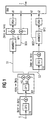
Figur 1 zeigt schematisch den Aufbau des Mehrfrequenz-Tonsignal-Empfängers, welcher grob in drei Verarbeitungsstufen eingeteilt werden kann. Eine erste Stufe enthält Dezimationsfilter D0 und D1. In dieser Stufe erfolgt eine Aufteilung des zugeführten Mehrfrequenz-Tonsignals S in einen oberen Frequenzbereich HG und einen unteren Frequenzbereich LG. Die zweite Verarbeitungsstufe ermittelt durch Einsatz von Notch-Wellendigitalfiltern ANWDF1 und ANWDF2 sowie Pegeldetektoren PD1 und PD2 die Frequenz des Tonsignals im oberen Frequenzbereich HG bzw. im unteren Frequenzbereich LG und die zugehörige Amplitude. Eine dritte Verarbeitungsstufe umfaßt eine Diskriminatoreinheit Rw, welche aus den ermittelten Amplituden und Frequenzen das übertragene Zeichen erkennt und ausgibt.FIG. 1 schematically shows the structure of the multi-frequency audio signal receiver, which roughly in three processing stages can be classified. A first stage contains decimation filters D0 and D1. At this stage, the supplied multi-frequency sound signal S in an upper frequency range HG and a lower frequency range LG. The second processing level determined by using Notch wave digital filters ANWDF1 and ANWDF2 as well as level detectors PD1 and PD2 the frequency of the sound signal in the upper frequency range HG or in the lower frequency range LG and the associated Amplitude. A third stage of processing includes one Discriminator unit Rw, which from the determined amplitudes and frequencies the transmitted character recognizes and outputs.
Im folgenden wird die Funktionsweise des Empfängers nach Figur
1 erläutert. Dem Dezimationsfilter D0 wird das Mehrfrequenz-Tonsignal
S als Digitalsignal zugeführt, welches üblicherweise
mit einer Abtastfrequenz von 8 kHz abgetatstet worden
ist. Aus Vereinfachungsgründen sind in Figur 1 die erforderliche
Hardware wie z.B. A/D-Wandler, Signalprozessor,
Speicher etc. weggelassen. Das Dezimationsfilter D0 enthält
ein Tiefpaßfilter DF0 und führt eine Abtastdatenreduktion um
den Faktor 2 durch, d.h. die vom Dezimationsfilter D0 ausgegebene
digitale Signalfolge hat eine Abtastrate von 4 kHz.
Das Dezimationsfilter D0 sowie die weiteren Dezimationsfilter
D1 und D2 sind rekursive bireziproke Brückenwellendigitalfilter,
deren Aufbau beschrieben sind in "Wave Digital Filters:
Theory and Practice", A. Fettweis, Proceedings of the IEEE,
Feb. 1986, pp. 270-327, im folgenden Literatur 1 genannt, und
in "Explicit Formulas for Lattice Wave Digital Filters", L.
Gazsi, IEEE Trans. on Circuits and Systems, Jan. 1985, pp.
68-88, im folgenden Literatur 2 genannt. Derartige Dezimationsfilter
werden mit einer Abtastratenreduktion um den Faktor
2 in der unteren Abtastrate betrieben. Sie haben einen rekursiven
Filteralgorithmus, wodurch sich der technische Aufwand
bei der Realisierung vermindert.The following is the operation of the receiver according to the figure
1 explained. The decimation filter D0 becomes the multi-frequency audio signal
S supplied as a digital signal, which is usually
was sampled with a sampling frequency of 8 kHz
is. For reasons of simplification, the required ones are shown in FIG
Hardware such as A / D converter, signal processor,
Memory etc. omitted. The decimation filter contains D0
a low pass filter DF0 and performs sample data reduction
by a factor of 2, i.e. the one output by the decimation filter D0
digital signal sequence has a sampling rate of 4 kHz.
The decimation filter D0 and the other decimation filters
D1 and D2 are recursive bi-reciprocal bridge wave digital filters,
their structure are described in "Wave Digital Filters:
Theory and Practice ", A. Fettweis, Proceedings of the IEEE,
Feb. 1986, pp. 270-327, hereinafter referred to as
Das durch das Dezimationsfilter gefilterte Signal S wird dem zweiten Dezimationsfilter D1 zugeführt, welches ein Bandpaßfilter DF1 enthält. Durch das Bandpaßfilter DF1 wird unter Ausnutzung der für solche Art von Dezimationsfilter ohne Mehraufwand vorhandenen komplementären Filterfunktion das Signal S in ein hochpaßgefiltertes Signal S1 und ein tiefpaßgefiltertes Signal S2 aufgeteilt. Ferner wird im Dezimationsfilter D1 eine weitere Abtastratenreduktion um den Faktor 2 durchgeführt, d.h. die Signale S1 und S2 sind mit einer Abtastrate von nunmehr 2 kHz behaftet. In den Dezimationsfiltern D0 und D1 wird ferner eine Hörtonunterdrückung bei 425 Hz durchgeführt, um eine Störeinwirkung dieses Hörtons auf die Signale S1 und S2 zu vermeiden.The signal S filtered by the decimation filter becomes the second decimation filter D1, which is a bandpass filter DF1 contains. Through the bandpass filter DF1 is under Exploitation of the decimation filter without such Additional effort available complementary filter function that Signal S into a high-pass filtered signal S1 and a low-pass filtered Split signal S2. Furthermore, the decimation filter D1 a further reduction in the sampling rate by a factor of 2 carried out, i.e. the signals S1 and S2 are at a sampling rate now has 2 kHz. In the decimation filters D0 and D1 also becomes audible suppression at 425 Hz performed to interfere with this audible tone on the Avoid signals S1 and S2.
Das hochfrequente Signal S1 wird in der zweiten Verarbeitungsstufe dem adaptiven Notch-Wellendigitalfilter ANWDF1 zugeführt. Dieses Notch-Wellendigitalfilter ANWDF1 wird zur Isolierung eines sinusförmigen Nutzsignals aus dem Signal S1 verwendet. Eine vorteilhafte Eigenschaft dieses Notch-Wellendigitalfilters ist die einfache, unabhängige Parametrisierung der Mittenfrequenz und der Bandbreite der Übertragungsfunktion. Weiterhin hat ein solches Filter sehr gute numerische Eigenschaften und läßt sich somit relativ einfach realisieren. Der Aufbau von Notch-Wellendigitalfilter ist z.B. beschrieben in dem Fachaufsatz "Adaptive Notch Wave Digital Filters", A. Zalnieriunas, Proceedings of ISCAS, New Orleans, USA, May 1990, im folgenden Literatur 3 genannt. Die bei diesem Ausführungsbeispiel verwendeten Notch-Wellendigitalfilter ANWDF1 und ANWDF2 sind als Brückenwellendigitalfilter zweiten Grades mit einem festen Filterkoeffizienten und einem adaptiven Filterkoeffizienten k1 bzw. k2 ausgeführt. Das Notch-Wellendigitalfilter ANWDF1 hat einen Bandsperrenausgang BS1 und einen dazu komplementären Bandpaßausgang BP1. Zur Adaption des Notch-Wellendigitalfilters ANWDF1, d.h. zur Einstellung des Frequenzganges wird der Bandsperrenausgang BS1 verwendet. Der adaptive Filterkoeffizient k1 wird über diesen Ausgang BS1 durch den Signalprozessor eingestellt. In der letztgenannten Literaturstelle wird detailliert erläutert, wie die Mittenfrequenz und die Bandbreite des Notch-Wellendigitalfilters ANWDF1 durch den festen Filterkoeffizienten und den adaptiven Filterkoeffizienten k1 definiert ist. Der Parameter k1 und damit die Mittenfrequenz des Notch-Wellendigitalfilters ANWDF1 wird so lange nachgestellt, bis ein Fehlersignal minimal wird. In diesem Zustand entspricht die Mittenfrequenz des Notch-Wellendigitalfilters ANWDF1 der zu detektierenden Tonfrequenz. Die Amplitude dieser Tonfrequenz ist am Ausgang BP1 des Bandpaßfilters zu ermitteln. In der vorgenannten Literaturstelle sind verschiedene Adaptionsalgorithmen erläutert. Das Signal am Ausgang des Notch-Wellendigitalfilters wird einer weiteren Abtastratenreduktion unterzogen, d.h. die Abtastfrequenz sinkt in dem Beispiel von 2 kHz auf 1 kKz. Das Signal wird dann dem Pegeldetektor PD1 zugeführt, welcher die Amplitude a1 des detektierten Tonsignals angibt. Die Pegeldetektoren PD1 und PD2 können auf der Basis einer Spitzenwertdetektion arbeiten, da im Falle von Sinussignalen als Tonsignale der Spitzenwert proportional der Signalenergie ist. Die nachgeschaltete Diskriminatoreinheit Rw stellt anhand der Amplitude a1 und des eingestellten Filterkoeffizientens k1 fest, ob ein Tonsignal vorliegt oder nicht.The high-frequency signal S1 is in the second processing stage the adaptive Notch wave digital filter ANWDF1 fed. This ANWDF1 notch wave digital filter becomes Isolation of a sinusoidal useful signal from the signal S1 used. An advantageous property of this Notch wave digital filter is the simple, independent parameterization the center frequency and the bandwidth of the transfer function. Furthermore, such a filter has very good numerical ones Properties and is therefore relatively easy to implement. The structure of Notch wave digital filters is e.g. described in the article "Adaptive Notch Wave Digital Filters ", A. Zalnieriunas, Proceedings of ISCAS, New Orleans, USA, May 1990, in the following literature 3. The one at this Embodiment used Notch wave digital filter ANWDF1 and ANWDF2 are second as bridge wave digital filters Degrees with a fixed filter coefficient and an adaptive Filter coefficients k1 and k2 executed. The Notch wave digital filter ANWDF1 has a bandstop output BS1 and a complementary bandpass output BP1. For adaptation of the Notch wave digital filter ANWDF1, i.e. for adjustment of the frequency response, the bandstop output BS1 is used. The adaptive filter coefficient k1 is via this output BS1 set by the signal processor. In the latter Literature is explained in detail how the Center frequency and the bandwidth of the Notch wave digital filter ANWDF1 through the fixed filter coefficient and the adaptive Filter coefficient k1 is defined. The parameter k1 and thus the center frequency of the Notch wave digital filter ANWDF1 is readjusted until an error signal becomes minimal. In this state the center frequency corresponds of the Notch wave digital filter ANWDF1 to be detected Audio frequency. The amplitude of this tone frequency is at the output Determine BP1 of the bandpass filter. In the aforementioned reference different adaptation algorithms are explained. The signal at the output of the Notch wave digital filter is subjected to a further sampling rate reduction, i.e. the Sampling frequency drops from 2 kHz to 1 kKz in the example. The Signal is then fed to the level detector PD1, which the Indicates amplitude a1 of the detected sound signal. The level detectors PD1 and PD2 can be based on peak detection work because in the case of sinusoidal signals as sound signals the peak value is proportional to the signal energy. The downstream discriminator unit Rw based on the Amplitude a1 and the set filter coefficient k1 determines whether there is a sound signal or not.
Das tiefpaßgefilterte Signal S2 wird einem dritten Dezimationsfilter D2 zugeführt, welches ein Hochpaßfilter DF2 enthält und eine Abtastratenreduktion um den Faktor 2 vornimmt, d.h. die Abtastrate am Ausgang des Dezimationsfilters D2 beträgt lediglich 1 kHz. Das so gefilterte Signal wird dem Notch-Wellendigitalfilter ANWDF2 zugeführt, welches einen Bandsperrenausgang BS2 und den Bandpaßausgang BP2 hat. Der Aufbau des Notch-Wellendigitalfilters ANWDF2 entspricht prinzipiell dem des Notch-Wellendigitalfilters ANWDF1, ist jedoch an die untere Tonsignalgruppe LG angepaßt. Auch bei diesem Notch-Wellendigitalfilter ANWDF2 wird die Mittenfrequenz mithilfe des Filterkoeffizientens k2 eingestellt. Die Amplitude am Ausgang BP2 wird mithilfe des Pegeldetektors PD2 ermittelt. Auch in diesem Fall stellt die Diskriminatoreinheit Rw anhand des Filterkoeffizienten k2 und der Amplitude a2 fest, ob ein Tonsignal in der unteren Tonsignalgruppe LG vorhanden ist oder nicht. Durch Verknüpfung der Tonsignale aus der oberen Tonsignalgruppe und der ermittelten Tonsignale der unteren Tonsignalgruppe ermittelt die Diskriminatoreinheit das im Mehrfrequenz-Tonsignal enthaltene Zeichen und gibt dies an eine übergeordnete Steuerung weiter.The low-pass filtered signal S2 becomes a third decimation filter D2 supplied, which contains a high-pass filter DF2 and performs a scan rate reduction by a factor of 2, i.e. the sampling rate at the output of the decimation filter is D2 only 1 kHz. The signal filtered in this way becomes the notch wave digital filter ANWDF2 fed which has a band stop output BS2 and the bandpass output BP2. The structure of the The ANWDF2 notch wave digital filter corresponds in principle to that of the Notch wave digital filter ANWDF1, but is at the bottom Sound signal group LG adapted. Also with this Notch wave digital filter ANWDF2 will use the Filter coefficient k2 set. The amplitude at the output BP2 is determined using the level detector PD2. Also in In this case, the discriminator unit Rw uses the Filter coefficients k2 and the amplitude a2 determines whether a sound signal is present in the lower tone signal group LG or Not. By linking the sound signals from the upper sound signal group and the determined audio signals of the lower audio signal group the discriminator unit determines that in the multi-frequency audio signal contained characters and gives this to a higher-level control.
Figur 2 zeigt in Diagrammen die Signale nach den verschiedenen Dezimationsfiltern, wobei die Signalamplituden des Hörtons HT, der Tonsignale der unteren Tonsignalgruppe LG und die Tonsignale der oberen Tonsignalgruppe HG über der Frequenz aufgetragen sind. Im oberen Bildteil ist zu erkennen, daß nach dem Durchlaufen des ersten Dezimationsfilters D0 bei einer reduzierten Abtastfrequenz von 4 kHz noch sämtliche Tonsignale vorhanden sind. Das Diagramm in der Mitte der Figur 2 zeigt das tiefpaßgefilterte Signal S2 nach dem Durchlaufen des dritten Dezimationsfilters D2, d.h. bei einer Abtastrate von 1 kHz. Im unteren Bildteil ist der Frequenzgang des hochpaßgefilterten Signals S1 nach Durchsetzen des zweiten Dezimationsfilters D1 dargestellt. Zu beachten ist, daß in den Signalen S1 und S2 der Hörton HT unterdrückt ist.Figure 2 shows the signals according to the different in diagrams Decimation filters, the signal amplitudes of the audible tone HT, the sound signals of the lower sound signal group LG and the sound signals of the upper sound signal group HG over the frequency are applied. In the upper part of the picture you can see that after passing through the first decimation filter D0 at a reduced sampling frequency of 4 kHz still all Sound signals are present. The diagram in the middle of the figure 2 shows the low-pass filtered signal S2 after passing through the third decimation filter D2, i.e. at a sampling rate of 1 kHz. In the lower part of the picture is the frequency response of the high-pass filtered signal S1 after enforcing the second Decimation filter D1 shown. It should be noted that the audio tone HT is suppressed in the signals S1 and S2.
Figur 3 zeigt die Auswertung der in den Amplituden a1 und a2
sowie den Filterkoeffizienten k1 und k2 enthaltenen Informationen
zum Ermitteln eines Zeichens anhand einer Darstellung
als Zustandsmaschine. Im Zustand 10 erfolgt die Initialisierung
im Signalprozessor für die Mehrfrequenz-Tonsignalauswertung.
Nach Einstellung der erforderlichen Parameter wird im
Zustand 12 die Mehrfrequenz-Tonsignalauswertung aktiviert und
es werden Mehrfrequenz-Tonsignale detektiert. Wenn kein Mehrfrequenz-Tonsignal
anliegt, so wird im Zustand 14 überprüft,
ob eine Pause größer als eine vorbestimmte Zeit T, z.B. größer
40 ms, vorhanden ist. Diese Information wird gespeichert.
Falls ein Vielfaches dieser Pause anliegt, so wird zum Zustand
10 verzweigt. Andernfalls wird zum Zustand 12 zurückgegeben.FIG. 3 shows the evaluation of the amplitudes a1 and a2
and the information contained in the filter coefficients k1 and k2
to determine a character based on a representation
as a state machine. Initialization takes place in
Der Zustand 16 wird eingestellt, wenn ein gültiges Mehrfrequenz-Tonsignal
ermittelt wurde. In diesem Zustand wird das
Ende des gültigen Tonsignals festgestellt. Wenn dieser Fall
eintritt, wird zum Zustand 10 verzweigt. Das erkannte Tonsignal
wird im Zustand 16 nur dann als gültig freigegeben, wenn
vorher eine hinreichend große Pause (vgl. Zustand 14) detektiert
worden ist.
Die Figuren 4 bis 6 zeigen weitere Ausführungsbeispiele der Erfindung, die es gestatten, eine weitestgehend multiplikationsfreie Anordnung mit weiter reduziertem Aufwand zu implementieren. Diese Ausführungsbeispiele sind insbesondere für den Einsatz mittels binärer Festkommaarithmetik und einer Wortlänge von 12 Bit geeignet. Die relativ kurze Wortlänge wird durch eine optimale Skalierung der Signale im Empfänger erreicht. Bei den adaptiven Notch-Wellendigitalfiltern ist speziell hierfür eine "adaptive" Skalierung realisiert worden.Figures 4 to 6 show further embodiments of the Invention that allow a largely multiplication-free Implement arrangement with further reduced effort. These embodiments are particularly for using binary fixed-point arithmetic and one Word length of 12 bits suitable. The relatively short word length is achieved by optimally scaling the signals in the receiver reached. With the adaptive notch wave digital filters "Adaptive" scaling has been implemented especially for this.
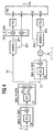
In Figur 4 ist ein Empfänger dargestellt, der nur geringfügig von dem nach Figur 1 abweicht. Die Abweichung besteht darin, daß vor dem zweiten Notch-Wellendigitalfilter ANWDF2 ein Negierglied M angeordnet ist. Dieses Negierglied M negiert jeden zweiten Wert der ankommenden digitalen Signalfolge, wie dies in Figur 4 in einem Klammerausdruck dargestellt ist. Durch diese Maßnahme wird eine Bandumkehr erreicht, wodurch sich die Konvergenzeigenschaften des in Figur 6 dargestellten und später erläuterten Adaptionsalgorithmus verbessern, welcher durch das zweite Notch-Wellendigitalfilter ANWDF2 realisiert ist.In Figure 4, a receiver is shown, which is only slightly from which differs according to Figure 1. The difference is that a negation element before the second notch wave digital filter ANWDF2 M is arranged. This negating member M negates everyone second value of the incoming digital signal sequence, such as this is shown in Figure 4 in brackets. A band reversal is achieved by this measure, whereby the convergence properties of that shown in Figure 6 and later explained adaptation algorithm improve which realized by the second Notch wave digital filter ANWDF2 is.
In Figur 5 ist der Frequenzgang des Empfängers in verschiedenen Teilbereichen nach Art der Figur 2 dargestellt. Zu erkennen ist, daß bei der unteren Tonsignalgruppe LG sich das Frequenzverhalten umgekehrt hat.In Figure 5, the frequency response of the receiver is different Subareas shown in the manner of Figure 2. To can be seen that in the lower tone signal group LG Frequency response has reversed.
Die verwendeten Dezimationsfilter DF0, DF1 und DF2 werden
vorzugsweise so realisiert, wie dies in der Literatur 2 vorgeschlagen
ist. Die Berechnung der Filterkoeffizienten γN für
Filter N-ten Grades ist dort beschrieben. Das Dezimationsfilter
DF1 wird vorzugsweise als rekursives bireziprokes
Brückenwellendigitalfilter siebten Grades mit den von Null
verschiedenen Filterkoeffizienten
Der Wert des Koeffizienten γ1 wird in Abhängigkeit des zu unterdrückenden Hörtons gewählt, und zwar so, daß die Nullstelle der Filter-Übertragungsfunktion mit der Frequenz des Hörtons übereinstimmt. Beispielsweise ist γ1 = -(2-1 + 2-3) für einen Hörton von 400 Hz zu wählen. Die Hörton-Freuqenz ist bekanntlich länderspezifisch festgelegt.The value of the coefficient γ1 is chosen as a function of the audible tone to be suppressed, in such a way that the zero of the filter transfer function corresponds to the frequency of the audible tone. For example, γ1 = - (2 -1 + 2 -3 ) should be selected for an audible tone of 400 Hz. The audible frequency is known to be country-specific.
Bei einem Hörton mit zwei Frequenzkomponenten im Bereich 0 Hz
bis 500 Hz ist ein rekursives bireziprokes Brückenwellendigitalfilter
fünften Grades einzusetzen, dessen Nullstellen dementsprechend
mit den Frequenzkomponenten des zu unterdrückenden
Hörtons übereinstimmen. With an audible tone with two frequency components in the
Die adaptiven Notch-Wellendigitalfilter ANWDF1 und ANWDF2 sind vorzugsweise Filter zweiten Grades mit einem festen Koeffizienten und einem adaptiven Koeffizienten. Diese Filter zeichnen sich durch die direkte Zuordnung zwischen der zu detektierenden Frequenz und den adaptiven Koeffizienten k1 und k2 aus. Die festen Koeffizienten werden für die Notch-Wellendigitalfilter ANWDF1 und ANWDF2 auf den Wert Null gesetzt. Dadurch wird der Aufwand der Realisierung verringert, insbesondere die Anzahl der Arithmetikblöcke wird reduziert.The adaptive notch wave digital filters ANWDF1 and ANWDF2 are preferably second degree filters with a fixed Coefficient and an adaptive coefficient. These filters are characterized by the direct assignment between the detecting frequency and the adaptive coefficient k1 and from. The fixed coefficients are used for the Notch wave digital filters ANWDF1 and ANWDF2 set to zero. This reduces the implementation effort, in particular the number of arithmetic blocks is reduced.
Der Entwurf von Notch-Wellendigitalfiltern ist in der Literatur 3 ausführlich beschrieben. Üblicherweise enthält ein solches Notch-Wellendigitalfilter zwei Arithmetikblöcke mit Adapterfunktionen. Bei dem vorliegenden Ausführungsbeispiel gemäß Figur 6 wird jedoch lediglich ein einziger Arithmetikblock verwendet. Der Implementierungsaufwand wird hierdurch erheblich reduziert und die Skalierung der Signale ist darüber hinaus einfach zu gestalten. Die Skalierung erfolgt in Abhängigkeit des variablen Koeffizienten und ist somit auch als "adaptiv" zu bezeichnen. Diese Skalierung ist gültig für den gesamten stabilen Wertebereich des variablen Koeffizienten und garantiert darüberhinaus den stetigen Übergang der Filterübertragungsfunktion bei stetiger Änderung des adaptiven Koeffizienten. Die Adaption der variablen Koeffizienten erfolgt durch einen Gradienten-Vorzeichen-Algorithmus.The design of Notch wave digital filters is in the literature 3 described in detail. Usually contains one Notch wave digital filter two arithmetic blocks with adapter functions. In the present embodiment 6, however, is only a single arithmetic block used. The implementation effort is thereby significantly reduced and the scaling of the signals is above that easy to design. The scaling is done in Dependence of the variable coefficient and is therefore also to be called "adaptive". This scaling is valid for the entire stable range of values of the variable coefficient and also guarantees the constant transition of the Filter transfer function with constant change of the adaptive Coefficients. The adaptation of the variable coefficients is carried out using a gradient sign algorithm.
Der Aufbau des Notch-Wellendigitalfilter ANWDF1 bzw. ANWDF2 inklusivie Skalierung und Koeffizientenadaption ist als Blockschaltbild in Figur 6 dargestellt. In diesem Blockschaltbild bedeutet T die Verzögerung um eine Abtastperiode, k der adaptive Koeffizient, s das Vorzeichen des adaptiven Koeffizienten k, -s das negierte Vorzeichen des adaptiven Koeffizienten k, + eine Addition, x eine Multiplikation, und sign die Ermittlung des Vorzeichens. The structure of the Notch wave digital filter ANWDF1 and ANWDF2 inclusive scaling and coefficient adaptation is as Block diagram shown in Figure 6. In this block diagram T means the delay by one sampling period, k the adaptive coefficient, s the sign of the adaptive Coefficients k, -s the negated sign of the adaptive Coefficients k, + an addition, x a multiplication, and sign the determination of the sign.
Die am Eingang ankommende Signalfolge wird zunächst mit dem
Schiebe-Faktor 2-1 multipliziert und sodann am Knoten 20 verteilt,
und zwar zu einem Verzögerungsglied 21, einem Summierglied
22 und mit umgekehrtem Vorzeichen zu einem Summierglied
24, an welchem das Ausgangssignal gebildet wird, entweder das
Ausgangssignal BP1 oder das Ausgangssignal BP2 (vgl. Figur
4). Das vom Verzögerungsglied 21 erzeugte Signal gelangt zum
Arithmetikblock 26, dessen Aufbau z.B. in Literatur 1, Tafel
10, Version D, beschrieben ist.The signal sequence arriving at the input is first multiplied by the
Abweichend hierzu ist beim vorliegenden Ausführungsbeispiel
eine bedingte Vorzeichenumkehr zweier Signalwerte ergänzt
worden. Die Umkehrung des jeweiligen Signal-Vorzeichens erfolgt
bei negativem Wert von s bzw. -s. Im Arithmetikblock
werden am Summierglied 28 die Summe aus dem Ausgang des Verzögerungsgliedes
30 und dem Ausgang des Verzögerungsgliedes
21, letzteres mit bedingter Vorzeichenumkehr, gebildet. Anschließend
wird das Ergebnis am Multiplizierglied 32 mit dem
Koeffizienten k multipliziert. Das Ergebnis wird den Summiergliedern
34, 36, letzteres mit bedingter Vorzeichenumkehr,
zugeführt, die auch das Ausgangssignal des Verzögerungsgliedes
21 bzw. das Ausgangssignal des Verzögerungsgliedes 30
erhalten. Das Ausgangssignal des Summiergliedes 34 bildet das
Eingangssignal für das Verzögerungsglied 30. Das Ausgangssignal
des Summiergliedes 36 verzweigt sich auf das Summierglied
22 und das Summierglied 24.The present embodiment differs from this
a conditional sign reversal of two signal values added
been. The respective signal sign is reversed
with a negative value of s or -s. In the arithmetic block
the sum of the output of the delay element at the summing
Das Ergebnis am Summierglied 28 wird nach Multiplikation mit
dem Schiebefaktor 2-1 dem Summierglied 38 zugeführt, dessen
Ausgangssignal dem Verzögerungsglied 40 sowie dem Summierglied
42, letzteres mit bedingter Vorzeichenumkehr, zugeführt
wird. Das Ausgangssignal des Verzögerungsgliedes 40 wird dem
Summierglied 42 und dem Multiplizierglied 50 zugeführt. Das
Ergebnis vom Multiplizierglied 50 wird wiederum dem Summierglied
38 zugeführt. Das Ausgangssignal des Summiergliedes 42
ist der Gradient vom Notch-Wellendigitalfilter bezogen auf
den Koeffizienten k. Vor der Weiterverarbeitung der Signalfolge
im Summierglied 42 wird im Block "sign" das Vorzeichen
ermittelt, welches als Eingangsgröße für das Multplikationsglied
44 dient, dem auch das Ergebnis des Summiergliedes 22
zugeführt ist.The result at the summing
Das Ergebnis des Multiplikationsgliedes 44 wird mit einem
Skalierungsfaktor u beaufschlagt und dann nach Vorzeichenumkehrung
dem Summierglied 46 zugeführt. Der Skalierungsfaktor
u bestimmt die Geschwindigkeit der Konvergenz der Adaption.
Dieser Skalierungsfaktor u wird vorzugsweise als eine Potenz
von 2 festgelegt und kann bei Bedarf, entweder über den Ausgang
des Pegeldetektors PD oder direkt über den Gradienten
gesteuert, nachgestellt werden. Dies ist besonders dann sinnvoll,
wenn der Empfang von kurzen Mehrfrequenz-Tonsignalen
mit einer Signaldauer von 40 ms gefordert ist. Der Skalierungsfaktor
u sollte in diesem Falle umgekehrt proportional
zum Steuersignal gewählt werden.The result of the
Das Ergebnis des Summiergliedes 46 gelangt zum Verzögerungsglied
48, dessen Ausgangssignal wiederum zum Summierglied 46
rückgeführt wird. Das Ausgangssignal des Verzögerungsgliedes
48 ist dann der Adaptionskoeffizient k, welcher als Eingangsgröße
den Multiplikationsgliedern 32 und 50 zugeführt wird.The result of the summing
Wie in Figur 6 zu erkennen ist, hat das Notch-Wellendigitalfilter
nur einen Arithmetikblock 26, einen Gradienten-Vorzeichen-Algorithmus
zur Koeffizientenadaption sowie eine
"adaptive" Skalierung auf Basis bedingter Vorzeichenumkehr
der relevanten Signale. Dies hat zur Folge, daß relativ wenig
Multiplikationen auszuführen sind bei sonst gleicher Filterleistung.
Die Funktion des beschriebenen Filters ist sehr
effizient. Z.B. bei einem Mikroprozessor µC68EC000 mit einer
Taktfrequenz von 10 MHz wurde innerhalb eines Zeitfensters
der Länge von 2 ms eine Prozessorlast von lediglich 11,3%
festgestellt. Ein Vergleich mit einem üblichen Goertzel-Algorithmus,
wie dies in der Literatur 3 vorgeschlagen wird, ergab
sich eine Prozessorlast von 36,8% unter sonst gleichen
Randbedingungen. Dies bedeutet, daß bei dem hier vorgeschlagenen
Filter der Mikroprozessor nur zu einem kleinen Teil
ausgelastet ist und weitere Aufgaben gleichzeitig erledigen
kann.As can be seen in Figure 6, the Notch wave digital filter
only one
Claims (22)
Applications Claiming Priority (2)
| Application Number | Priority Date | Filing Date | Title |
|---|---|---|---|
| DE19740173 | 1997-09-12 | ||
| DE19740173 | 1997-09-12 |
Publications (2)
| Publication Number | Publication Date |
|---|---|
| EP0903899A2 true EP0903899A2 (en) | 1999-03-24 |
| EP0903899A3 EP0903899A3 (en) | 2001-08-01 |
Family
ID=7842173
Family Applications (1)
| Application Number | Title | Priority Date | Filing Date |
|---|---|---|---|
| EP98115498A Withdrawn EP0903899A3 (en) | 1997-09-12 | 1998-08-17 | Method and apparatus for evaluating Multifrequency tone signals using an adaptive wave digital notch filter |
Country Status (1)
| Country | Link |
|---|---|
| EP (1) | EP0903899A3 (en) |
Cited By (5)
| Publication number | Priority date | Publication date | Assignee | Title |
|---|---|---|---|---|
| WO2001031891A3 (en) * | 1999-10-28 | 2001-09-20 | Siemens Ag | Method for processing a sinusoidal transmission signal |
| WO2001031932A3 (en) * | 1999-10-28 | 2002-02-07 | Siemens Ag | Method and receiver for processing a signal generated according to the multi-frequency dialing method |
| CN102281045A (en) * | 2011-04-15 | 2011-12-14 | 深圳大学 | Method for constructing subband self-adapting filter |
| US20120119754A1 (en) * | 2009-05-19 | 2012-05-17 | Abb Ag | Method and device for insulation monitoring of non-grounded electrical dc and ac grids |
| CN121356579A (en) * | 2025-12-17 | 2026-01-16 | 深圳市斯帕克电气有限公司 | Software-based algorithm-based ADC noise filtering method for 50Hz or 60Hz |
Family Cites Families (1)
| Publication number | Priority date | Publication date | Assignee | Title |
|---|---|---|---|---|
| US5392348A (en) * | 1991-11-25 | 1995-02-21 | Motorola, Inc. | DTMF detection having sample rate decimation and adaptive tone detection |
-
1998
- 1998-08-17 EP EP98115498A patent/EP0903899A3/en not_active Withdrawn
Cited By (7)
| Publication number | Priority date | Publication date | Assignee | Title |
|---|---|---|---|---|
| WO2001031891A3 (en) * | 1999-10-28 | 2001-09-20 | Siemens Ag | Method for processing a sinusoidal transmission signal |
| WO2001031932A3 (en) * | 1999-10-28 | 2002-02-07 | Siemens Ag | Method and receiver for processing a signal generated according to the multi-frequency dialing method |
| US20120119754A1 (en) * | 2009-05-19 | 2012-05-17 | Abb Ag | Method and device for insulation monitoring of non-grounded electrical dc and ac grids |
| US8994379B2 (en) * | 2009-05-19 | 2015-03-31 | Abb Ag | Method and device for insulation monitoring of non-grounded electrical DC and AC grids |
| CN102281045A (en) * | 2011-04-15 | 2011-12-14 | 深圳大学 | Method for constructing subband self-adapting filter |
| WO2012139357A1 (en) * | 2011-04-15 | 2012-10-18 | 深圳大学 | Method for constructing subband self-adaptive filter |
| CN121356579A (en) * | 2025-12-17 | 2026-01-16 | 深圳市斯帕克电气有限公司 | Software-based algorithm-based ADC noise filtering method for 50Hz or 60Hz |
Also Published As
| Publication number | Publication date |
|---|---|
| EP0903899A3 (en) | 2001-08-01 |
Similar Documents
| Publication | Publication Date | Title |
|---|---|---|
| EP0212307B1 (en) | Ripple control receiver | |
| EP0830771B1 (en) | Method and circuit arrangement for improving carrier separation for the transmission of ofdm signals | |
| EP0290790B1 (en) | Filter bank | |
| DE3541031A1 (en) | Method and device for demodulating RF-modulated signals by means of digital filters and digital demodulators, and use of the method in a remote-control receiver | |
| DE69224625T2 (en) | METHOD FOR DETECTING A DISABLE SOUND SIGNAL FROM AN ECHOCOMPENSATOR | |
| DE2558402C3 (en) | Digital multi-frequency code signal receiver for telecommunications, in particular telephone switching systems | |
| DE2917285A1 (en) | DIGITAL SPECTRAL ANALYZER | |
| DE2707936C3 (en) | Single sideband frequency division multiplex transmission system | |
| EP0234452B1 (en) | Digital circuit arrangement for sampling rate conversion and signal filtration, and method for making it | |
| DE68907098T2 (en) | Differential encoder with auto-adaptive predictor filter and associated decoder. | |
| EP0105087B1 (en) | Digital filter for a remote control receiver | |
| EP0903899A2 (en) | Method and apparatus for evaluating Multifrequency tone signals using an adaptive wave digital notch filter | |
| EP0901225A2 (en) | Digital tunable filter device | |
| DE69628130T2 (en) | Digital narrow band filter | |
| DE3922469C2 (en) | ||
| EP0284734B1 (en) | Circuit for the recognition of dual tone multifrequency signals in telephone exchanges | |
| EP0256286B1 (en) | Filter device | |
| EP0609707B1 (en) | Process for detecting the instantaneous frequency | |
| EP0599144B1 (en) | Method for generating a modified video signal | |
| EP1515447B1 (en) | Method for noise suppression in a signal processing system and signal processing system | |
| DE3831047C2 (en) | ||
| DE69015193T2 (en) | CIRCUIT FOR AUDIO SIGNAL PROCESSING. | |
| EP0902575A2 (en) | Method and apparatus for evaluating Multifrequency tone signals using an adaptive wave digital notch filter | |
| DE3418011C2 (en) | ||
| EP0795959A1 (en) | Asymmetric filter combination for a digital transmission system |
Legal Events
| Date | Code | Title | Description |
|---|---|---|---|
| PUAI | Public reference made under article 153(3) epc to a published international application that has entered the european phase |
Free format text: ORIGINAL CODE: 0009012 |
|
| AK | Designated contracting states |
Kind code of ref document: A2 Designated state(s): DE FR GB IT |
|
| AX | Request for extension of the european patent |
Free format text: AL;LT;LV;MK;RO;SI |
|
| PUAL | Search report despatched |
Free format text: ORIGINAL CODE: 0009013 |
|
| AK | Designated contracting states |
Kind code of ref document: A3 Designated state(s): AT BE CH CY DE DK ES FI FR GB GR IE IT LI LU MC NL PT SE |
|
| AX | Request for extension of the european patent |
Free format text: AL;LT;LV;MK;RO;SI |
|
| 17P | Request for examination filed |
Effective date: 20011217 |
|
| AKX | Designation fees paid |
Free format text: DE FR GB IT |
|
| STAA | Information on the status of an ep patent application or granted ep patent |
Free format text: STATUS: THE APPLICATION IS DEEMED TO BE WITHDRAWN |
|
| 18D | Application deemed to be withdrawn |
Effective date: 20060301 |