EP1567768B1 - Unterwasser angeordnete laufkraftturbine - Google Patents
Unterwasser angeordnete laufkraftturbine Download PDFInfo
- Publication number
- EP1567768B1 EP1567768B1 EP03779928A EP03779928A EP1567768B1 EP 1567768 B1 EP1567768 B1 EP 1567768B1 EP 03779928 A EP03779928 A EP 03779928A EP 03779928 A EP03779928 A EP 03779928A EP 1567768 B1 EP1567768 B1 EP 1567768B1
- Authority
- EP
- European Patent Office
- Prior art keywords
- rotor
- axle
- power plant
- hydroelectric power
- flow
- Prior art date
- Legal status (The legal status is an assumption and is not a legal conclusion. Google has not performed a legal analysis and makes no representation as to the accuracy of the status listed.)
- Expired - Lifetime
Links
- XLYOFNOQVPJJNP-UHFFFAOYSA-N water Substances O XLYOFNOQVPJJNP-UHFFFAOYSA-N 0.000 claims abstract description 38
- 230000007246 mechanism Effects 0.000 claims description 10
- 238000001816 cooling Methods 0.000 claims description 3
- 230000001131 transforming effect Effects 0.000 abstract 1
- 230000006835 compression Effects 0.000 description 7
- 238000007906 compression Methods 0.000 description 7
- 238000006243 chemical reaction Methods 0.000 description 5
- 230000009467 reduction Effects 0.000 description 4
- 238000011144 upstream manufacturing Methods 0.000 description 3
- 230000009471 action Effects 0.000 description 2
- 238000005452 bending Methods 0.000 description 2
- 238000010276 construction Methods 0.000 description 2
- 238000009434 installation Methods 0.000 description 2
- 238000012423 maintenance Methods 0.000 description 2
- 238000004873 anchoring Methods 0.000 description 1
- 230000008859 change Effects 0.000 description 1
- 235000013490 limbo Nutrition 0.000 description 1
- 238000004519 manufacturing process Methods 0.000 description 1
- 230000004048 modification Effects 0.000 description 1
- 238000012986 modification Methods 0.000 description 1
- 230000008439 repair process Effects 0.000 description 1
- 239000000725 suspension Substances 0.000 description 1
- 239000003643 water by type Substances 0.000 description 1
Images


Classifications
-
- F—MECHANICAL ENGINEERING; LIGHTING; HEATING; WEAPONS; BLASTING
- F03—MACHINES OR ENGINES FOR LIQUIDS; WIND, SPRING, OR WEIGHT MOTORS; PRODUCING MECHANICAL POWER OR A REACTIVE PROPULSIVE THRUST, NOT OTHERWISE PROVIDED FOR
- F03B—MACHINES OR ENGINES FOR LIQUIDS
- F03B17/00—Other machines or engines
- F03B17/06—Other machines or engines using liquid flow with predominantly kinetic energy conversion, e.g. of swinging-flap type, "run-of-river", "ultra-low head"
- F03B17/061—Other machines or engines using liquid flow with predominantly kinetic energy conversion, e.g. of swinging-flap type, "run-of-river", "ultra-low head" with rotation axis substantially in flow direction
-
- F—MECHANICAL ENGINEERING; LIGHTING; HEATING; WEAPONS; BLASTING
- F05—INDEXING SCHEMES RELATING TO ENGINES OR PUMPS IN VARIOUS SUBCLASSES OF CLASSES F01-F04
- F05B—INDEXING SCHEME RELATING TO WIND, SPRING, WEIGHT, INERTIA OR LIKE MOTORS, TO MACHINES OR ENGINES FOR LIQUIDS COVERED BY SUBCLASSES F03B, F03D AND F03G
- F05B2240/00—Components
- F05B2240/20—Rotors
- F05B2240/202—Rotors with adjustable area of intercepted fluid
- F05B2240/2022—Rotors with adjustable area of intercepted fluid by means of teetering or coning blades
-
- F—MECHANICAL ENGINEERING; LIGHTING; HEATING; WEAPONS; BLASTING
- F05—INDEXING SCHEMES RELATING TO ENGINES OR PUMPS IN VARIOUS SUBCLASSES OF CLASSES F01-F04
- F05B—INDEXING SCHEME RELATING TO WIND, SPRING, WEIGHT, INERTIA OR LIKE MOTORS, TO MACHINES OR ENGINES FOR LIQUIDS COVERED BY SUBCLASSES F03B, F03D AND F03G
- F05B2240/00—Components
- F05B2240/40—Use of a multiplicity of similar components
-
- Y—GENERAL TAGGING OF NEW TECHNOLOGICAL DEVELOPMENTS; GENERAL TAGGING OF CROSS-SECTIONAL TECHNOLOGIES SPANNING OVER SEVERAL SECTIONS OF THE IPC; TECHNICAL SUBJECTS COVERED BY FORMER USPC CROSS-REFERENCE ART COLLECTIONS [XRACs] AND DIGESTS
- Y02—TECHNOLOGIES OR APPLICATIONS FOR MITIGATION OR ADAPTATION AGAINST CLIMATE CHANGE
- Y02E—REDUCTION OF GREENHOUSE GAS [GHG] EMISSIONS, RELATED TO ENERGY GENERATION, TRANSMISSION OR DISTRIBUTION
- Y02E10/00—Energy generation through renewable energy sources
- Y02E10/20—Hydro energy
Definitions
- the invention relates to a hydropower plant for generating electrical energy while converting the flow energy of a flowing body of water, by means of a turbomachine with at least one rotor, a generator driven by the rotor and a float for the turbomachine, wherein the turbomachine anchors stationary and the rotor in the flow direction of Water body is aligned, further wherein the turbomachine below the surface of the water kept in suspension and to the float with either a gaseous medium, eg Compressed air, can be acted upon and flooded with water, and wherein the rotor is mounted on a rotor axis aligned in the direction of flow of the water body.
- rotor blade and impellers and propellers multi-wing or the like.
- hydroelectric power plants can produce continuous electrical energy because of the constant flow of flowing water.
- hydropower plants of the embodiment described above which have a floating on the water surface turbomachine. This is on the one hand aesthetically unsatisfactory because the landscape is disturbed, on the other hand, a reduced energy conversion must be accepted, because the rotor in the embodiment as a regular paddle wheel only partially immersed in the flowing water and is driven (see. DE 41 12 730 C2 ).
- turbomachinery for use in underwater power plants, in which paddle wheels are arranged on a scaffold and the framework is placed on a foundation in the bottom of the water.
- the sinking of the foundation is complex and a sufficient anchoring of the scaffold on the foundation hardly guaranteed, so that a sufficient alignment of the paddle wheels in the flow direction is hardly guaranteed (see. DE 200 11 874 U1 ).
- the rotor's axis of rotation is rotatably mounted at the lower end with a pin in a bearing.
- This warehouse is located in a multi-part foundation whose individual foundation parts must be swum to the place of use and assembled there with a diver's aid at the bottom of the water (cf. DE 299 00 124 U1 ).
- the invention is based on the technical problem of developing such a hydropower plant so that the turbomachine is not visible in use, allows for a short-term installation and also characterized by a simple construction with optimized flow conditions in terms of assembly and maintenance.
- pressurizing the float to the surface of the water can be lifted.
- the lifting and lowering operation of the turbomachine can be controlled via a compressed air line by supplying air, possibly also by way of flooding. A lowering of the turbomachine to the bottom of the water is possible.
- the hollow shaft forming the floating body is characterized by high bending stiffness and supports the orientation of the rotor in the flow direction of the flowing water.
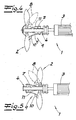
- the rotor blades of the rotor shaft rotatably mounted on the rotor are swiveled in the flow direction and kept upright by spring action against the flow pressure and are swung when the flow pressure is exceeded by a predetermined amount successively in the flow direction with reduction of the inflow.
- a relatively simple and functional adjustment mechanism for the rotor blades is achieved. This is especially true if the rotor blades are supported on their side facing away from the flow by means of supporting lugs against spread-apart leaf springs, which are distributed over the circumference of the rotor axis and fixed on the rotor axis.
- the spring force of these leaf springs defines that flow pressure at which the rotor blades are held upright. Only when the flow pressure exceeds the spring force of the leaf springs, the rotor blades are pivoted in the same feathered position.
- an abutment is arranged on the rotor axis, wherein the rotor blades are articulated steering levers and the steering levers are articulated on a displaceable on the rotor axis in the axial longitudinal direction bearing ring and further wherein between the abutment and the bearing ring a surrounding the rotor axis compression spring the embodiment of a helical spring is arranged, which acts on the rotor blades via the steering lever and against the flow direction of the water body.
- the rotor blades are pivoted when the effective flow pressure exceeds the spring force of the compression spring.
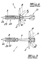
- the rotor axis may be formed as at least at the front and rear axis end spindle axis, wherein the abutment and / or the bearing for the rotor blades are designed as adjustable and lockable spindle nuts on the spindle axis to bias the compression spring by a predetermined amount or to vary the spring pressure can.
- a spindle-axis surrounding helical compression spring or tension spring is arranged between the bearing ring and the bearing for the rotor blades, wherein the bearing ring and the bearing for the rotor blades are designed as spindle nuts. In this case, it depends on the direction of flow and thus loading of the rotor blades from one direction or the other, whether the spring arranged between the bearing ring and the bearing for the rotor blades works as a compression spring or tension spring.
- the invention teaches that a plurality of rotors, each with adjusting mechanism is arranged at predetermined intervals on the rotor axis.
- the flow pressure from the flowing water is distributed to a plurality of rotor blades, so that even low flow rates allow sufficient energy conversion.
- a reduction of the flow pressure is achieved by its distribution to the individual rotor blades. This is especially true when the outer diameter of the rotors or their rotor blades increase in the flow direction of the water by a predetermined gradation and exceed the upstream rotors.
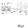
- the rotor axis is designed as a conical widening in the flow direction of the body hollow axis and characterized not only by a streamlined design, but also reduces the attacking on the flanged generator stresses and in particular bending forces.
- the hollow axle is expediently constructed and extendable from hollow sections forming axle sections, each having a rotor, wherein the shaft sections can be connected to one another by means of gas-tight or air-tight and watertight flange connections. This allows the rotor axis with sufficient stability and buoyancy optionally extend.
- the rear end of the rotor axis in the flow direction may have a tail, so that proper alignment of the rotor axis and the rotors thereon is ensured.
- the generator can be placed in a watertight housing, e.g. B. housings of half-shells such as pipe halves to be arranged with outside cooling fins, which preferably in the housing longitudinal direction and consequently flow direction run.
- a watertight housing e.g. B. housings of half-shells such as pipe halves to be arranged with outside cooling fins, which preferably in the housing longitudinal direction and consequently flow direction run.
- several generators are arranged in series one behind the other and connected to each other and to the rotor axis in order to achieve an optimal energy conversion into electrical current.
- a hollow flow cone can be flanged to the housing upstream, which also provides buoyancy in the generator area.
- the float is preferably formed by the hollow axle, optionally the housing and the flow cone.
- the floating body is formed by a frame with hollow beams and / or boxes for one or more turbomachines.
- turbomachines are arranged in series next to one another and / or in a staggered arrangement one behind the other and, if appropriate, connected to one another by means of flexible or elastic connecting means in order, as it were, to realize a power plant.
- the turbomachinery or machines are anchored by means of chains, hawser or the like on the shore or bottom of the water, so that in the latter case, the anchor remains invisible.
- a hydropower plant for generating electrical energy or electric current with conversion of flow energy of a flowing water.
- This hydroelectric power plant has at least one turbomachine 1 with at least one rotor 2, a driven by the rotor 2 generator 3 and a float 4 for the turbomachine 1, wherein the turbomachine 1 stationary, z. B. is anchored to shore-side and / or water-base fixed points 5, that the rotor 2 is aligned in the direction of flow of the water.
- the turbomachine 1 is held below the surface of the water 6 in a floating state.
- the float 4 is optionally acted upon by compressed air or other gaseous medium and optionally flooded with water. The necessary valve and control devices are not shown.
- the rotor 2 is mounted on a rotor axis 7 aligned in the direction of flow of the body of water. Its rotor blades 8 are adjustable by means of an adjusting mechanism 9 in or against the flow direction. In addition, the rotor blades 8 can be adjusted to change their angle of attack about their longitudinal axis.
- the respective rotor axis 7 is designed as a hollow axle, which at the same time forms the floating body 4. If the rotor axis 7 is not configured as a hollow axle, these are illustrations that are not designed according to the invention, but nevertheless serve for better understanding.
- the rotor blades 8 of the rotatably mounted on the rotor axis 7 rotor 2 are swung in the flow direction and kept upright by spring action against the flow pressure.
- the rotor blades 8 are successively swiveled in the flow direction while reducing the inflow surface in the feathering position. This is indicated by dashed lines.
- the rotor blades 8 are supported on their side facing away from the flow by means of supporting lugs 10 against spread-apart leaf springs 11, which are distributed over the circumference of the rotor axis 7 and fixed on the rotor axis 7.
- an abutment 12 is arranged on the rotor axis 7.
- rotor axis 7 may be formed at least at the front and rear axle end as a spindle axis 7a, 7b, wherein the abutment 12 and / or the bearing 16 are formed for the rotor blades 8 as on the spindle axis 7a, 7b adjustable and lockable spindle nuts.
- a spindle axis 7 surrounding helical compression spring 15 ' is disposed between the bearing ring 14 and the bearing 16 for the rotor blades 8, which can also operate as a tension spring depending on the flow direction.
- the bearing ring 14 and the bearing 16 for the rotor blades 8 are formed as spindle nuts.
- a plurality of rotors 2 may be arranged with respective adjusting mechanism 9 at predetermined intervals.
- the outer diameter of the rotors 2 and their rotor blades 8 increase in the flow direction of the water by a predetermined gradation and exceed the upstream rotors, which as it were an indicated flow cone is formed.
- an embodiment of the rotor axis 7 is recommended as a hollow shaft which widens conically in the flow direction of the water body and is connected with its tapered end to a generator 3.
- the hollow axle may be composed of hollow sections 17 forming axle sections 18, each having a rotor 2 and adjusting mechanism 9 and consequently be extendible by a plurality of axle sections 18.
- axle sections 18 can be connected to one another by means of gas or airtight and watertight flange connections 19.
- gas or airtight and watertight flange connections 19 it is possible to support the rotor axis 7 at predetermined intervals by means of guide bearings 20.
- the downstream end of the rotor axis 7 has a tail 21, whereby the orientation of the turbomachine 1 is stabilized in the flow direction.
- the generator 3 may be in a housing 22, for. B. from half shells housing with outside cooling fins 23 may be arranged. It is also possible to arrange a plurality of generators 3 in series one behind the other and to connect them to one another and to the rotor axis 7. Also in this case, the generators 3 can be housed. Preferably, on the inflow side of the housing 22, a hollow flow cone 24 is flanged.
- the floating body 4 is formed by the hollow shaft 7, optionally the housing 22 and the flow cone 24.
- the floating body 4 is formed by a frame 25 with hollow beams 26 and / or boxes for one or more turbomachines 1. This frame 25 may be equipped for placement with skids 27.
- turbomachines 1 At the floodable floating body 4, one or more compressed air lines 28 are connected.
- a plurality of turbomachines 1 can be arranged in series next to each other and / or in a staggered arrangement one behind the other and optionally connected to one another by means of flexible or flexurally elastic connecting means 29.
- the turbomachine or machines 1 are anchored by means of chains, hawser 30 or the like on the shore 31 and / or bottom 32 of the water in fixed points 5. With an anchorage at the bottom 32 of the water body, one can bring in a strike or boring pile 33, dispensing with a complex foundation.
Landscapes
- Engineering & Computer Science (AREA)
- Power Engineering (AREA)
- Chemical & Material Sciences (AREA)
- Combustion & Propulsion (AREA)
- Mechanical Engineering (AREA)
- General Engineering & Computer Science (AREA)
- Other Liquid Machine Or Engine Such As Wave Power Use (AREA)
- Hydraulic Turbines (AREA)
- Wind Motors (AREA)
Applications Claiming Priority (3)
| Application Number | Priority Date | Filing Date | Title |
|---|---|---|---|
| DE10256864A DE10256864B4 (de) | 2002-12-05 | 2002-12-05 | Wasserkraftanlage |
| DE10256864 | 2002-12-05 | ||
| PCT/EP2003/012731 WO2004051079A1 (de) | 2002-12-05 | 2003-11-14 | Unterwasser angeordnete laufkraftturbine |
Publications (2)
| Publication Number | Publication Date |
|---|---|
| EP1567768A1 EP1567768A1 (de) | 2005-08-31 |
| EP1567768B1 true EP1567768B1 (de) | 2010-04-21 |
Family
ID=32403709
Family Applications (1)
| Application Number | Title | Priority Date | Filing Date |
|---|---|---|---|
| EP03779928A Expired - Lifetime EP1567768B1 (de) | 2002-12-05 | 2003-11-14 | Unterwasser angeordnete laufkraftturbine |
Country Status (12)
| Country | Link |
|---|---|
| US (1) | US7487637B2 (pl) |
| EP (1) | EP1567768B1 (pl) |
| JP (1) | JP4535378B2 (pl) |
| CN (1) | CN100476198C (pl) |
| AU (1) | AU2003288063B2 (pl) |
| BR (1) | BR0316982B1 (pl) |
| CA (1) | CA2508377C (pl) |
| DE (2) | DE10256864B4 (pl) |
| MX (1) | MXPA05005933A (pl) |
| PL (1) | PL207540B1 (pl) |
| RU (1) | RU2309289C2 (pl) |
| WO (1) | WO2004051079A1 (pl) |
Families Citing this family (36)
| Publication number | Priority date | Publication date | Assignee | Title |
|---|---|---|---|---|
| GB0306093D0 (en) * | 2003-03-18 | 2003-04-23 | Soil Machine Dynamics Ltd | Submerged power generating apparatus |
| RU2330966C2 (ru) * | 2006-02-20 | 2008-08-10 | Дмитрий Анатольевич Капачинских | Винт-турбина |
| ES2299361B1 (es) * | 2006-07-06 | 2009-05-01 | Diego Valenzuela Abucha | Central acuatica rotativa generadora de electricidad. |
| DE102006044332B3 (de) * | 2006-09-19 | 2008-01-03 | Karl Stern | Rotorflügel |
| DE102006044330B4 (de) * | 2006-09-19 | 2010-11-11 | Karl Stern | Flügelrotor |
| US8575775B1 (en) * | 2007-09-19 | 2013-11-05 | Julio Gonzalez-Carlo | Electrical power generation system for harvesting underwater currents |
| FR2930300B1 (fr) * | 2008-04-22 | 2011-10-21 | Nheolis | Pale pour appareil de generation d'energie a partir d'un ecoulement fluidique pouvant etre de l'air ou de l'eau |
| CA2734748A1 (en) * | 2008-08-22 | 2010-02-25 | Natural Power Concepts, Inc. | Folding blade turbine |
| US8915697B2 (en) * | 2008-08-22 | 2014-12-23 | Natural Power Concepts Inc. | Mobile wind turbine |
| WO2011089604A2 (en) | 2010-01-20 | 2011-07-28 | Theracoat Ltd | Material and method for treating internal cavities |
| DE202010001796U1 (de) | 2010-02-04 | 2010-06-10 | Stein Ht Gmbh Spezialtiefbau | Wasserkraftanlage |
| GB201021596D0 (en) * | 2010-07-15 | 2011-02-02 | Guangzhou Suntrans Measurement & Control System Co Ltd | Wave power generation device and method |
| CN102182613A (zh) * | 2011-01-26 | 2011-09-14 | 余戈平 | 发电装置 |
| CN102808734A (zh) * | 2011-06-01 | 2012-12-05 | 臧国栋 | 无级变量风力发电机组 |
| DE102011105178A1 (de) * | 2011-06-17 | 2012-12-20 | Robert Bosch Gmbh | Wellenenergiekonverter und Verfahren zum Betreiben eines Wellenenergiekonverters |
| WO2013011504A1 (en) | 2011-07-20 | 2013-01-24 | Theracoat Ltd. | Materials and method for treating internal body cavities |
| FR2980245B1 (fr) * | 2011-09-19 | 2014-07-04 | Sabella | Dispositif de recuperation d'energie a partir des courants marins ou des cours d'eau |
| JP2013096403A (ja) * | 2011-11-01 | 2013-05-20 | Yaheitai Hayashi | 発電(動力)用として流体中に設置するタービン(水車、風車)のための、浮力(比重)調整機能と流体方向誘導機能を備え、縦列多重連結設置を可能とする外構装置。 |
| CN102570715A (zh) * | 2012-02-06 | 2012-07-11 | 哈尔滨电机厂有限责任公司 | 潮流能发电机直接热交换冷却结构 |
| DE102012012096A1 (de) * | 2012-06-18 | 2013-12-19 | Robert Bosch Gmbh | Verfahren zum Betreiben eines Wellenenergiekonverters zur Umwandlung von Energie aus einer Wellenbewegung eines Fluids in eine andere Energieform |
| JP5976414B2 (ja) * | 2012-06-22 | 2016-08-23 | 株式会社東芝 | 水流発電装置 |
| CN103321824B (zh) * | 2013-05-31 | 2015-08-05 | 闫传桂 | 远洋深海集能发电装置 |
| GB201318841D0 (en) * | 2013-10-28 | 2013-12-11 | Tidal Energy Ltd | Tidal Turbine System |
| GB2524331B (en) * | 2014-03-21 | 2016-06-01 | Flumill As | Hydrokinetic energy conversion system and use thereof |
| GB2531596A (en) * | 2014-10-24 | 2016-04-27 | Tidal Energy Ltd | Tidal turbine system |
| KR20170046928A (ko) * | 2015-10-22 | 2017-05-04 | 지유 주식회사 | 소형 풍력발전기의 블레이드 폴딩 조절장치 |
| KR101691933B1 (ko) * | 2016-05-24 | 2017-01-02 | 유원기 | 조류 발전기 |
| DE202017102221U1 (de) * | 2017-04-12 | 2018-07-13 | Rolf Rohden | Turbine und Gezeitenkraftwerk |
| CN108999738B (zh) * | 2018-07-17 | 2020-05-26 | 白玉平 | 一种新式的适用于小河道的水力发电设备 |
| US11118560B2 (en) * | 2019-01-22 | 2021-09-14 | Gregory Francis Bird | Electrical energy generating systems, apparatuses, and methods |
| CN110307111B (zh) * | 2019-05-20 | 2021-09-28 | 湖南天尚科技有限公司 | 一种水泵水轮调节装置 |
| US10738755B1 (en) * | 2019-10-24 | 2020-08-11 | On Hoter-Ishay | Hydrostatic pressure turbines and turbine runners therefor |
| GB2601721A (en) * | 2020-07-10 | 2022-06-15 | Cdr Systems Ltd | Fluid turbine |
| CA3099992A1 (en) * | 2020-11-19 | 2022-05-19 | Aurea Technologies INC. | Portable wind turbine |
| US11754035B2 (en) * | 2021-04-12 | 2023-09-12 | Loubert S. Suddaby | Assembly for capturing oscillating fluid energy with hinged propeller and segmented driveshaft |
| PL244320B1 (pl) | 2021-07-05 | 2024-01-08 | Blacha Bartlomiej | Urządzenie do przetwarzania energii kinetycznej naturalnego cieku wodnego, zwłaszcza rzeki na energię mechaniczną i jej przekształcania na energię elektryczną |
Family Cites Families (22)
| Publication number | Priority date | Publication date | Assignee | Title |
|---|---|---|---|---|
| US1570421A (en) * | 1921-08-29 | 1926-01-19 | Abraham Adolf | Water-power engine for utilizing low-grade water powers |
| US1461502A (en) * | 1922-02-15 | 1923-07-10 | Solinger Power Company | Current motor |
| GB200027A (en) * | 1922-11-20 | 1923-07-05 | Henry Robert Solinger | Improvements in and relating to water and wind wheels |
| DE647287C (de) * | 1934-10-24 | 1937-07-01 | Walter Conrad Dipl Ing Dr | Windkraftmaschine mit propelleraehnlichen, in der Windrichtung umklappbaren Windradfluegeln |
| AT170460B (de) * | 1946-01-12 | 1952-02-25 | Ernst Dr Ing Souczek | Stromturbine |
| US2730631A (en) * | 1953-03-30 | 1956-01-10 | Juliana S Dandini | Current-driven motor |
| DE1503349A1 (de) * | 1964-02-18 | 1970-01-15 | Otto Roll | Krafterzeugungsapparat |
| US4095918A (en) | 1975-10-15 | 1978-06-20 | Mouton Jr William J | Turbine wheel with catenary blades |
| US4245473A (en) * | 1977-08-22 | 1981-01-20 | Sandoval Dante J | Fluid motor |
| US4317046A (en) * | 1980-12-04 | 1982-02-23 | Richard Holmberg | Energy producing apparatus and method |
| US4462211A (en) * | 1983-07-08 | 1984-07-31 | Linderfelt Hal R | Apparatus for harvesting wave energy |
| CN86108973A (zh) * | 1986-12-11 | 1987-11-11 | 张国祥 | 浮水发电机 |
| US4868408A (en) * | 1988-09-12 | 1989-09-19 | Frank Hesh | Portable water-powered electric generator |
| DE4112730C2 (de) * | 1991-02-26 | 1998-07-23 | Johann Christoph Riedel | Vorrichtung zur Erzeugung von elektrischem Strom durch Wasserkraft |
| RU2049929C1 (ru) * | 1992-06-30 | 1995-12-10 | Общество с ограниченной ответственностью "Малые инновационные системы" | Свободнопоточная оперативная гидроэнергетическая установка |
| RU2153041C2 (ru) * | 1998-08-04 | 2000-07-20 | Гинкулов Георгий Владимирович | Донная гидроэлектростанция |
| GB2340892A (en) * | 1998-08-21 | 2000-03-01 | Norman Frank Surplus | Water driven pump |
| US6109863A (en) * | 1998-11-16 | 2000-08-29 | Milliken; Larry D. | Submersible appartus for generating electricity and associated method |
| DE29900124U1 (de) * | 1999-01-07 | 1999-04-01 | Günther, Eggert, 18209 Bad Doberan | Vertikalachsrotor als Unterwasser-Strömungsmaschine zur Energiegewinnung |
| DE20011874U1 (de) * | 2000-06-29 | 2000-11-30 | Stern, Karl, 15344 Strausberg | Strömungsmaschine zur Verwendung im Unterwasserkraftwerk |
| JP3435540B2 (ja) * | 2001-02-13 | 2003-08-11 | 章 小幡 | 風力発電装置 |
| ITMI20012505A1 (it) * | 2001-11-29 | 2003-05-29 | Roberto Pizzigalli | Apparecchiatura idrodinamica per la generazione di corrente elettrica |
-
2002
- 2002-12-05 DE DE10256864A patent/DE10256864B4/de not_active Expired - Fee Related
-
2003
- 2003-11-14 JP JP2004556141A patent/JP4535378B2/ja not_active Expired - Fee Related
- 2003-11-14 PL PL376884A patent/PL207540B1/pl unknown
- 2003-11-14 WO PCT/EP2003/012731 patent/WO2004051079A1/de not_active Ceased
- 2003-11-14 BR BRPI0316982-0A patent/BR0316982B1/pt not_active IP Right Cessation
- 2003-11-14 CN CNB2003801049640A patent/CN100476198C/zh not_active Expired - Fee Related
- 2003-11-14 RU RU2005121136/06A patent/RU2309289C2/ru not_active IP Right Cessation
- 2003-11-14 EP EP03779928A patent/EP1567768B1/de not_active Expired - Lifetime
- 2003-11-14 CA CA2508377A patent/CA2508377C/en not_active Expired - Fee Related
- 2003-11-14 DE DE50312645T patent/DE50312645D1/de not_active Expired - Lifetime
- 2003-11-14 MX MXPA05005933A patent/MXPA05005933A/es active IP Right Grant
- 2003-11-14 AU AU2003288063A patent/AU2003288063B2/en not_active Ceased
- 2003-11-14 US US10/537,730 patent/US7487637B2/en not_active Expired - Lifetime
Also Published As
| Publication number | Publication date |
|---|---|
| DE10256864A1 (de) | 2004-07-08 |
| WO2004051079A1 (de) | 2004-06-17 |
| JP2006509147A (ja) | 2006-03-16 |
| JP4535378B2 (ja) | 2010-09-01 |
| BR0316982A (pt) | 2005-10-25 |
| RU2005121136A (ru) | 2006-03-20 |
| DE10256864B4 (de) | 2007-09-06 |
| PL207540B1 (pl) | 2010-12-31 |
| DE50312645D1 (de) | 2010-06-02 |
| PL376884A1 (pl) | 2006-01-09 |
| AU2003288063A1 (en) | 2004-06-23 |
| CN100476198C (zh) | 2009-04-08 |
| US7487637B2 (en) | 2009-02-10 |
| MXPA05005933A (es) | 2005-12-05 |
| CA2508377C (en) | 2010-01-26 |
| CA2508377A1 (en) | 2004-06-17 |
| US20060127210A1 (en) | 2006-06-15 |
| EP1567768A1 (de) | 2005-08-31 |
| BR0316982B1 (pt) | 2013-02-19 |
| AU2003288063B2 (en) | 2008-04-17 |
| RU2309289C2 (ru) | 2007-10-27 |
| CN1720394A (zh) | 2006-01-11 |
Similar Documents
| Publication | Publication Date | Title |
|---|---|---|
| EP1567768B1 (de) | Unterwasser angeordnete laufkraftturbine | |
| DE69902524T2 (de) | Energiegewinnung aus sich bewegendem wasser | |
| DE10205988B4 (de) | Windenergieanlage | |
| EP1467091B1 (en) | Floating water current turbine with counter rotating coaxial rotors | |
| DE60320400T2 (de) | Vorrichtung für in tiefwasser angeordnete windenergiestation | |
| WO1982003662A1 (fr) | Installation pour l'exploitation du vent et des vagues | |
| NZ531809A (en) | Water current turbine sleeve mounting | |
| US20200370530A1 (en) | System for generating electric energy from wind or hydraulic energy | |
| EP2003332A1 (de) | Wasserkraftanlage | |
| EP4067640A1 (de) | Meeresströmungskraftwerk | |
| DE102005040803A1 (de) | Kombinierte schwimmende Wind- und Wasser-Energieanlage | |
| DE10036314A1 (de) | Mobiles Unterwasserkraftwerk | |
| DE102012022858B3 (de) | Strömungskraftwerk | |
| WO2013017213A1 (de) | Wasserkraftwerk | |
| DE202010016041U1 (de) | Windkraftanlage und Windpark | |
| AT527653B1 (de) | Vorrichtung zur Gewinnung elektrischer Energie aus Strömungsenergie eines strömenden Gewässers | |
| DE212014000161U1 (de) | Energieanlage | |
| DE102005040797A1 (de) | Schwimmende Trägerbasistür Offshore-Windenergieanlagen | |
| AU2004200198B2 (en) | Water current turbine pitch control | |
| DE29900124U1 (de) | Vertikalachsrotor als Unterwasser-Strömungsmaschine zur Energiegewinnung | |
| AU2007202995B2 (en) | Water current turbine pitch control | |
| DE102010005717A1 (de) | Energiegewinnungsanlage | |
| DE2817552A1 (de) | Wasser- und windkraftmaschine | |
| DE202023101522U1 (de) | Spiralrotorvorrichtung für fluidgetriebene Energieerzeugung, Montagebausatz sowie Verwendung | |
| DE202021003974U1 (de) | Offshore- Strömungskraftanlage zur Stromgewinnung |
Legal Events
| Date | Code | Title | Description |
|---|---|---|---|
| PUAI | Public reference made under article 153(3) epc to a published international application that has entered the european phase |
Free format text: ORIGINAL CODE: 0009012 |
|
| 17P | Request for examination filed |
Effective date: 20050528 |
|
| AK | Designated contracting states |
Kind code of ref document: A1 Designated state(s): AT BE BG CH CY CZ DE DK EE ES FI FR GB GR HU IE IT LI LU MC NL PT RO SE SI SK TR |
|
| AX | Request for extension of the european patent |
Extension state: AL LT LV MK |
|
| DAX | Request for extension of the european patent (deleted) | ||
| RBV | Designated contracting states (corrected) |
Designated state(s): DE FR GB IT |
|
| RAP1 | Party data changed (applicant data changed or rights of an application transferred) |
Owner name: STEIN HT GMBH SPEZIALTIEFBAU |
|
| RIN1 | Information on inventor provided before grant (corrected) |
Inventor name: BUTTLER, ERNST |
|
| 17Q | First examination report despatched |
Effective date: 20080305 |
|
| GRAP | Despatch of communication of intention to grant a patent |
Free format text: ORIGINAL CODE: EPIDOSNIGR1 |
|
| GRAS | Grant fee paid |
Free format text: ORIGINAL CODE: EPIDOSNIGR3 |
|
| GRAA | (expected) grant |
Free format text: ORIGINAL CODE: 0009210 |
|
| AK | Designated contracting states |
Kind code of ref document: B1 Designated state(s): DE FR GB IT |
|
| REG | Reference to a national code |
Ref country code: GB Ref legal event code: FG4D Free format text: NOT ENGLISH |
|
| REF | Corresponds to: |
Ref document number: 50312645 Country of ref document: DE Date of ref document: 20100602 Kind code of ref document: P |
|
| PLBE | No opposition filed within time limit |
Free format text: ORIGINAL CODE: 0009261 |
|
| STAA | Information on the status of an ep patent application or granted ep patent |
Free format text: STATUS: NO OPPOSITION FILED WITHIN TIME LIMIT |
|
| 26N | No opposition filed |
Effective date: 20110124 |
|
| REG | Reference to a national code |
Ref country code: FR Ref legal event code: PLFP Year of fee payment: 13 |
|
| REG | Reference to a national code |
Ref country code: FR Ref legal event code: PLFP Year of fee payment: 14 |
|
| REG | Reference to a national code |
Ref country code: FR Ref legal event code: PLFP Year of fee payment: 15 |
|
| PGFP | Annual fee paid to national office [announced via postgrant information from national office to epo] |
Ref country code: DE Payment date: 20191120 Year of fee payment: 17 |
|
| PGFP | Annual fee paid to national office [announced via postgrant information from national office to epo] |
Ref country code: FR Payment date: 20191120 Year of fee payment: 17 Ref country code: IT Payment date: 20191128 Year of fee payment: 17 |
|
| PGFP | Annual fee paid to national office [announced via postgrant information from national office to epo] |
Ref country code: GB Payment date: 20191120 Year of fee payment: 17 |
|
| REG | Reference to a national code |
Ref country code: DE Ref legal event code: R119 Ref document number: 50312645 Country of ref document: DE |
|
| GBPC | Gb: european patent ceased through non-payment of renewal fee |
Effective date: 20201114 |
|
| PG25 | Lapsed in a contracting state [announced via postgrant information from national office to epo] |
Ref country code: FR Free format text: LAPSE BECAUSE OF NON-PAYMENT OF DUE FEES Effective date: 20201130 Ref country code: IT Free format text: LAPSE BECAUSE OF NON-PAYMENT OF DUE FEES Effective date: 20201114 |
|
| PG25 | Lapsed in a contracting state [announced via postgrant information from national office to epo] |
Ref country code: GB Free format text: LAPSE BECAUSE OF NON-PAYMENT OF DUE FEES Effective date: 20201114 Ref country code: DE Free format text: LAPSE BECAUSE OF NON-PAYMENT OF DUE FEES Effective date: 20210601 |