EP1567747B1 - Verfahren zur installation eines unterirdischen futterrohrs - Google Patents
Verfahren zur installation eines unterirdischen futterrohrs Download PDFInfo
- Publication number
- EP1567747B1 EP1567747B1 EP03711396A EP03711396A EP1567747B1 EP 1567747 B1 EP1567747 B1 EP 1567747B1 EP 03711396 A EP03711396 A EP 03711396A EP 03711396 A EP03711396 A EP 03711396A EP 1567747 B1 EP1567747 B1 EP 1567747B1
- Authority
- EP
- European Patent Office
- Prior art keywords
- hammer
- pipe casing
- pipe
- diameter
- casing
- Prior art date
- Legal status (The legal status is an assumption and is not a legal conclusion. Google has not performed a legal analysis and makes no representation as to the accuracy of the status listed.)
- Expired - Lifetime
Links
- 238000000034 method Methods 0.000 title claims abstract description 34
- 238000005520 cutting process Methods 0.000 claims abstract description 54
- 239000000314 lubricant Substances 0.000 claims description 31
- 238000005461 lubrication Methods 0.000 claims description 10
- 238000009826 distribution Methods 0.000 claims description 8
- 230000035939 shock Effects 0.000 claims description 6
- 239000006096 absorbing agent Substances 0.000 claims description 4
- 241000269627 Amphiuma means Species 0.000 claims 1
- FGUUSXIOTUKUDN-IBGZPJMESA-N C1(=CC=CC=C1)N1C2=C(NC([C@H](C1)NC=1OC(=NN=1)C1=CC=CC=C1)=O)C=CC=C2 Chemical compound C1(=CC=CC=C1)N1C2=C(NC([C@H](C1)NC=1OC(=NN=1)C1=CC=CC=C1)=O)C=CC=C2 FGUUSXIOTUKUDN-IBGZPJMESA-N 0.000 claims 1
- 238000013016 damping Methods 0.000 claims 1
- 238000005259 measurement Methods 0.000 claims 1
- 238000004513 sizing Methods 0.000 claims 1
- 239000002689 soil Substances 0.000 abstract description 24
- 238000009434 installation Methods 0.000 description 13
- 230000005641 tunneling Effects 0.000 description 13
- 229910000278 bentonite Inorganic materials 0.000 description 11
- 239000000440 bentonite Substances 0.000 description 11
- SVPXDRXYRYOSEX-UHFFFAOYSA-N bentoquatam Chemical compound O.O=[Si]=O.O=[Al]O[Al]=O SVPXDRXYRYOSEX-UHFFFAOYSA-N 0.000 description 11
- 125000006850 spacer group Chemical group 0.000 description 7
- 238000009412 basement excavation Methods 0.000 description 6
- 238000010276 construction Methods 0.000 description 5
- 229910000831 Steel Inorganic materials 0.000 description 4
- 238000010586 diagram Methods 0.000 description 4
- 239000012530 fluid Substances 0.000 description 4
- 239000010959 steel Substances 0.000 description 4
- 230000008901 benefit Effects 0.000 description 3
- 230000007613 environmental effect Effects 0.000 description 3
- 230000009969 flowable effect Effects 0.000 description 3
- 239000000463 material Substances 0.000 description 3
- 238000003466 welding Methods 0.000 description 3
- IJGRMHOSHXDMSA-UHFFFAOYSA-N Atomic nitrogen Chemical compound N#N IJGRMHOSHXDMSA-UHFFFAOYSA-N 0.000 description 2
- 229910001018 Cast iron Inorganic materials 0.000 description 2
- 239000004567 concrete Substances 0.000 description 2
- 238000011109 contamination Methods 0.000 description 2
- 230000001276 controlling effect Effects 0.000 description 2
- 230000008878 coupling Effects 0.000 description 2
- 238000010168 coupling process Methods 0.000 description 2
- 238000005859 coupling reaction Methods 0.000 description 2
- 230000001419 dependent effect Effects 0.000 description 2
- 238000004519 manufacturing process Methods 0.000 description 2
- 241000251468 Actinopterygii Species 0.000 description 1
- 241000196324 Embryophyta Species 0.000 description 1
- XEEYBQQBJWHFJM-UHFFFAOYSA-N Iron Chemical group [Fe] XEEYBQQBJWHFJM-UHFFFAOYSA-N 0.000 description 1
- 241000219470 Mirabilis Species 0.000 description 1
- 239000000654 additive Substances 0.000 description 1
- XAGFODPZIPBFFR-UHFFFAOYSA-N aluminium Chemical compound [Al] XAGFODPZIPBFFR-UHFFFAOYSA-N 0.000 description 1
- 229910052782 aluminium Inorganic materials 0.000 description 1
- 239000003575 carbonaceous material Substances 0.000 description 1
- 238000004891 communication Methods 0.000 description 1
- 230000006835 compression Effects 0.000 description 1
- 238000007906 compression Methods 0.000 description 1
- 239000007789 gas Substances 0.000 description 1
- 230000005484 gravity Effects 0.000 description 1
- 230000003116 impacting effect Effects 0.000 description 1
- 238000005304 joining Methods 0.000 description 1
- 230000014759 maintenance of location Effects 0.000 description 1
- 239000000203 mixture Substances 0.000 description 1
- 238000012986 modification Methods 0.000 description 1
- 230000004048 modification Effects 0.000 description 1
- 229910052757 nitrogen Inorganic materials 0.000 description 1
- 239000002245 particle Substances 0.000 description 1
- 239000011178 precast concrete Substances 0.000 description 1
- 238000002360 preparation method Methods 0.000 description 1
- 230000008569 process Effects 0.000 description 1
- 230000001681 protective effect Effects 0.000 description 1
- 230000001105 regulatory effect Effects 0.000 description 1
- 239000011435 rock Substances 0.000 description 1
- 238000000926 separation method Methods 0.000 description 1
- 239000007787 solid Substances 0.000 description 1
- 239000000725 suspension Substances 0.000 description 1
- XLYOFNOQVPJJNP-UHFFFAOYSA-N water Substances O XLYOFNOQVPJJNP-UHFFFAOYSA-N 0.000 description 1
Images


Classifications
-
- E—FIXED CONSTRUCTIONS
- E21—EARTH OR ROCK DRILLING; MINING
- E21D—SHAFTS; TUNNELS; GALLERIES; LARGE UNDERGROUND CHAMBERS
- E21D9/00—Tunnels or galleries, with or without linings; Methods or apparatus for making thereof; Layout of tunnels or galleries
- E21D9/04—Driving tunnels or galleries through loose materials; Apparatus therefor not otherwise provided for
-
- E—FIXED CONSTRUCTIONS
- E21—EARTH OR ROCK DRILLING; MINING
- E21B—EARTH OR ROCK DRILLING; OBTAINING OIL, GAS, WATER, SOLUBLE OR MELTABLE MATERIALS OR A SLURRY OF MINERALS FROM WELLS
- E21B7/00—Special methods or apparatus for drilling
- E21B7/20—Driving or forcing casings or pipes into boreholes, e.g. sinking; Simultaneously drilling and casing boreholes
- E21B7/205—Driving or forcing casings or pipes into boreholes, e.g. sinking; Simultaneously drilling and casing boreholes without earth removal
-
- E—FIXED CONSTRUCTIONS
- E21—EARTH OR ROCK DRILLING; MINING
- E21D—SHAFTS; TUNNELS; GALLERIES; LARGE UNDERGROUND CHAMBERS
- E21D9/00—Tunnels or galleries, with or without linings; Methods or apparatus for making thereof; Layout of tunnels or galleries
- E21D9/005—Tunnels or galleries, with or without linings; Methods or apparatus for making thereof; Layout of tunnels or galleries by forcing prefabricated elements through the ground, e.g. by pushing lining from an access pit
-
- F—MECHANICAL ENGINEERING; LIGHTING; HEATING; WEAPONS; BLASTING
- F16—ENGINEERING ELEMENTS AND UNITS; GENERAL MEASURES FOR PRODUCING AND MAINTAINING EFFECTIVE FUNCTIONING OF MACHINES OR INSTALLATIONS; THERMAL INSULATION IN GENERAL
- F16L—PIPES; JOINTS OR FITTINGS FOR PIPES; SUPPORTS FOR PIPES, CABLES OR PROTECTIVE TUBING; MEANS FOR THERMAL INSULATION IN GENERAL
- F16L1/00—Laying or reclaiming pipes; Repairing or joining pipes on or under water
- F16L1/024—Laying or reclaiming pipes on land, e.g. above the ground
- F16L1/028—Laying or reclaiming pipes on land, e.g. above the ground in the ground
- F16L1/036—Laying or reclaiming pipes on land, e.g. above the ground in the ground the pipes being composed of sections of short length
Definitions
- the present invention relates to the field of trenchless tunneling by jacking or ramming pipe casing of large diameter over long distances, especially with respect to the installation of 30 ⁇ 48-121 ⁇ 92 metres (100-400 feet) of pipe casing which is larger than 1 ⁇ 829 metres (72 inches) in diameter.
- trenchless tunneling There are various methods currently used to install underground pipe without digging trenches, commonly referred to as trenchless tunneling. These methods use pipe ramming and jacking, tunnel boring machines, or Micro-Tunneling.
- Trenchless tunneling methods use tunnel boring machines that include a boring shield that either pushes itself forward with completed extruded segments either made from precast concrete or bolted steel panels. Variation on the boring method has the TBM or mole mounted on or in front of the first casing pipe that is thereafter pushed into the formed tunnel with large hydraulic jacks. As these tunnel boring machines move forward through the ground, the soil is removed and typically mixed with a fluid and the mixture pumped out of the tunnel into a separation plant, wherein the solids are separated from the fluids. These methods do not work well in shallow applications, depending on soil type. A minimum industry standard requirement is a cover over the tunnel to be installed of at least two times the machine diameter. Tunnel boring is very slow and very expensive because of the type of equipment required.
- TBM or Micro-tunneling involves underground trenchless tunneling in which energy is used to excavate the soil loose during the tunneling operation for soil removal. Again, Micro-tunneling is very slow in terms of the time required to create a tunnel and can be quite expensive.
- Trenchless tunneling methods that use pipe ramming or pipe jacking are known (see US 5240352 and US 4146347 ).
- the method typically uses a casing liner that is pushed underground into the tunnel by either a pneumatic ramming hammer, a set of hydraulic rams in tandem, or a combination of the two.
- the tunnel is typically started in a jacking pit that is dug to a depth to which a casing pipe or tunnel liner will be placed under the ground.
- U.S. Patent No. 5,632,575 issued May 27, 1997 describes a method and apparatus for controlled piping of bentonite around a pipe-jacked tunnel.
- this patent shows trenchless tunneling, it may use a combination of a tunnel boring machine or even tunnel excavation using hand labor.
- the system uses a tunnel ram and requires lubrication that presses the limit of the hydraulic jacking. This is a completely different operation than pile driving a tunnel casing great lengths using a horizontal pile driver.
- U.S. Patent No. 4,557,672 issued December 10, 1985 shows an apparatus and method for tunnel construction with shield drive. Again, this is a trenchless tunneling method that is completely different than Applicant's invention. This method uses a shield drive and incorporates a concrete tunnel lining directly behind the shield. This is very slow and expensive.
- U.S. Patent No. 4,398,845 issued August 16, 1983 shows a tunnel driving apparatus that incorporates a cutter shield with a plurality of drive members in a side-by-side, cylindrical array. This system is completely different than that employed by Applicant.
- the subject of the present invention overcomes the problems discussed above by providing a method and system that uses a powerful pile driving hammer, like those used for offshore vertical pile driving construction, that greatly increases the length of a trenchless tunnel casing to be driven while greatly reducing the risk of cave-in.
- a powerful pile driving hammer like those used for offshore vertical pile driving construction, that greatly increases the length of a trenchless tunnel casing to be driven while greatly reducing the risk of cave-in.
- the Applicant can use trenchless tunneling to drive underground pipe casing over 1 ⁇ 829m (72 inches) in diameter and up to 4 ⁇ 267m (168 inches) for distances exceeding 30 ⁇ 48m (100 feet). This can also be done very quickly in a matter of hours instead of days and weeks compared to other methods of trenchless tunneling at greatly reduced cost.
- an impact piling (pile driving) hammer such as a modified Hydrohammer manufactured by IHC
- a low energy, low velocity, and high frequency system such as ramming
- pipe ramming/ jacking are especially evident for installation done in damp or fluid-bearing soils where the pneumatic ramming can lead to soil liquification that can cause the soil plug to run.
- Another advantage of the large capacity available with the low frequency and high velocity and high energy system in accordance with the present invention using a piling hammer is that on particularly environmentally sensitive projects, a hammer of sufficient driving capacity can be chosen so as to eliminate the need to lubricate.
- the system avoids environmental contamination when the installation, for example, is near or over fish-bearing creeks.
- lubrication it also allows for even more increased distance that can be obtained using the pile driving hammer in accordance with the present invention.
- a trenchless tunneling system and method for driving horizontally placed large pipe casings that are joined sequentially together in sections to form a tunnel which is safer and more efficient over current methods.
- the present invention can provide for the creation of a tunnel using casings of large diameter (over 72 inches) for great lengths (exceeding 100 feet) without digging a trench.
- One objective of the invention is to provide a method and system for installation of pipe casings in areas where open cut excavation is not possible or practical, such as under heavily traveled roads, highways, railroads, or any combination thereof.
- a hammer of sufficient capacity may be chosen in accordance with the present invention to eliminate the need to lubricate with bentonite or other additives, avoiding environmental contamination.
- Another object of the invention is to provide a hammer of sufficient capacity that on less environmentally sensitive projects, especially where tunnel distances are required exceeding 300 feet trenchless, the invention can provide a method and apparatus for providing lubricant, such as bentonite, on the inside or outside or both, for great distances.
- lubricant such as bentonite
- Yet another object of the invention is to provide a method that temporarily stabilizes soil at the entry phase of the casing pipe to be installed whenever the entry of the installation is near the shoulder of a road, a railroad embankment, or other structure requiring settlement avoidance.
- a temporary means of soil support is provided at the leading open end of the pipe as soon as the drive is started to avoid collapse of the soil into the pipe, resulting in loss ground and surface settlement.
- a temporary seal made up of interlocking steel plates against the cutting shoe form an enclosure at the front end, thus a temporary bulkhead, whilst at a variable distance, dependent upon the soil type to be tunneled, a temporary bulkhead is placed inside the casing to be driven in such a way that the space between the two bulkheads can then be filled with a flowable fill.
- the rear bulkhead is constructed out of aluminum, and is a shield that uses an inflatable rubber seal of which the friction between the interface with the internal diameter of the casing pipe may be controlled by means of regulating the pressure in the inflatable seal; this bulkhead together with the flowable fill plug forms a controllable resistance that will support the face upon entry, thereby avoiding surface settlement.
- the invention is used to install a large steel pipe casing of up to 4 ⁇ 267m (168 inches) diameter, up to two inches thickness, a distance of at least 76 ⁇ 2m (250 feet) underground without digging a trench to install the pipe.
- soil is removed, and the desired final pipe is placed in the casing.
- This could be a large concrete water or sewerage pipe placed inside the permanent pipe casing. All this is accomplished without digging a trench.
- the overall installation involves digging a ground entrance pit and placing a pile driving hammer of significant driving force and a support system horizontally in the pit forming an entrance to the under ground tunnel to be driven.
- the installation requires that the pipe casing be formed by a series of pipe casing segments, each about 9 ⁇ 144m (30 feet) (or smaller) in length, that are sequentially joined (end-to-end) as each pipe casing segment is driven until the desired total length of the pipe casing is achieved underground without a trench.
- a new section is added either by welding or by a coupling device.
- a large pile driving hammer 12 is placed in a pit generally horizontally in front of the location where the pipe 18 is to be installed.
- a pit may be required, although, depending upon the job, a pit may not be necessary.
- the hammer is placed on a stability framework fixed to the ground to ensure that the hammer head strikes generally evenly.
- the pile driving hammer is similar to a vertical pile driving hammer modified for horizontal use to compensate for the loss of the "g" force of gravity used by vertical hammers.
- the driving end of the hammer 12 head strikes a helmet 14 abutting plate 16.
- the plate 16 is mounted against helmet 14.
- This helmet also referred to as the primary helmet, preferably strikes a secondary helmet, which, in its turn, may strike a series of helmets that may be used depending upon the diameter of casing pipe to be driven.
- the final helmet when there is a series of helmets, then strikes a drive plate, which in turn strikes the first section of casing pipe 18 to be driven.
- the lead casing 18 has a cutting head 20 described below. Depending on the soil and application, the cutting head may be steerable. Subsequently when the first casing pipe has been driven, the driving apparatus, including the drive helmets, is withdrawn from the first casing pipe.
- the connection between the first and second casing pipe may be formed through the use of a proprietary locking joint, or through welding.
- the driving apparatus and helmets with push ring are placed against the driven end of the second casing pipe whereafter the above described driving process is repeated. This sequence will repeat itself until the last casing pipe is driven.
- Each casing may be up to thirty feet in length.
- the hammer head is approximately 0 ⁇ 610-0 ⁇ 914m (24-36 inches) in diameter; and the plate is approximately 1 ⁇ 626m (64 inches) in diameter, and preferably made of a rigid material.
- the hollow helmet or helmets, and the pipe to be inserted are preferred to be up to approximately 3 ⁇ 048m (120 inches) in diameter and may be 4.064 or up to 4.826m (160 or up to 190 inches) in diameter.
- the hammer 12 is preferably a high energy impact hammer (generally 81 ⁇ 349-352 ⁇ 513 kJ (60,000-260,000 foot/pounds)) such as one used in large offshore vertical piling construction projects. In use, the hammer hits approximately 40-60 blows per minute, and can drive 9 ⁇ 144m (30 feet) of large diameter pipe on average in about 35 minutes. However, unlike offshore construction, the hammer is used horizontally rather than vertically. Several elements must be in place to ensure that the hammer operates as intended. Larger hammers may be used as necessary up to 677 ⁇ 909 kJ (500,000 foot/pounds).
- FIG. 1A shows a schematic diagram of the high force, horizontal pile driver 12 used to drive the pipe casing 110 and the drive hammer set-up when driving horizontally.
- a constant tension loading device pulse down force
- a spring arrangement 116 is located between tension wires 114 and the hammer 118 to prevent too high shock loads in these wires.
- the system incorporates a winch that includes a plurality of lines and pulleys and springs attached to pulleys that are permanently mounted to the earth to provide the constant tension through a constant tension loading device (CTLD).
- CTLD constant tension loading device
- the pile driving hammer 118 is not in itself the present invention but is the hammer being used that includes improvements for specifically driving pipe casing horizontally to avoid having to dig trenches.
- Figures 2A and 2B show the present invention which includes the pile driving hammer 12 connected to helmets 14 and pipe casing 18 in the pipe driving position.
- the hammer is supported on a frame 20.
- the system includes a tension cable 24, a winch 22 and pulleys 26, 28 and 32 mounted to rigid pilings 34 and 34a.
- An end cap 30a and cable tension shock absorbing devices 30 hold the hammer in alignment and in tension.
- FIG 3 shows a side view of an improved helmet 40 used with the present invention.
- the use of the improved helmet 40 reduces the overall length required for the pile driving hammer pit in as much as a good portion of the hammer 12 is mounted inside the helmet 40.
- the helmet 40 itself is mounted partially inside the first casing pipe to be driven.
- the hammer end 12a strikes interior mounted anvil 46 constructed of T1 high carbon material inside the helmet40.
- the helmet 40 is an elongated cylindrical cast iron unit that has an elongated circular central chamber 40c that receives the driver hammer 12 which provides the high impact force to anvil 40 positioned permanently inside the helmet interior chamber 40c.
- the helmet flanged end 40a is conical in shape and makes direct contact with a plate connected directly to the pipe casing section being driven and provides the force transferred from the hammer 12 through the helmet 40 against the entire perimeter edge of the pipe casing being driven.
- the end of the helmet includes a conical flange portion with an extended circular area that extends beyond the cylindrical outer body of the hammer.
- the hammer is aligned by a plurality of spacers 41 positioned between the outer hammer 12 body surface and the inside chamber 40c against anvil 46.
- the flanged conical end 40a of helmet is shaped so as to be able to engage pipe casings of different diameters through, including additional flanged ends 42 and 44 to extend the helmet diameter for larger pipe.
- the helmet 40 includes an adjustable sized diameter for different diameter pipes for different jobs without having to create a separate helmet for each different size pipe casing.
- the helmet itself is made of high-strength cast-iron and sized in length to save approximately 4 ⁇ 572-6 ⁇ 096m (15-20 feet) of excavation in the initial hammer installation pit by allowing a significant portion of the hammer to be received inside the helmet and impacting the anvil inside the helmet 40, all while the helmet is partially received inside the first casing pipe.
- the hammer 12 is placed on a ground supporting framework 20.
- a tension bracket 30a incorporating pulleys with shock absorbers are attached.
- two pulleys 26 and 28 are firmly attached either directly or indirectly into the ground to pilings 34 generally behind the entry seal.
- Two other pulleys 31 are firmly fixed in a position generally located near the bracket 30a fixed to the body of the hammer.
- the shock absorbers help dampen the rebound of the hammer as it is used, helps provide a constant tension on the hammer, and helps stabilize the invention.
- the pulley system attachment to the piling 34a has a load cell in the dead end of the system so as to be able to maintain a constant tension through out the pulley system. It is preferred that the load cell has a PLC controlling the hydraulic winch 22.
- the pulley system preferably provides a one to five mechanical advantage.
- the impetus for the hammer 12 is preferably provided by a hydraulic cylinder which is actuated by compression of a nitrogen cylinder.
- other force drivers for providing impetus are known in the art.
- the cutting head 20 is a tubular or annular-shaped conduit 50 that has a hardened knife blade shaped leading cutting edge 56 around its perimeter cutting through rock and ground as the pipe casing is driven.
- the blade edge 56 extends around the entire perimeter of the leading edge of the cutting head.
- the cutting head 20 back perimeter 58 is welded to the leading edge of the first pipe casing that will be driven to begin the tunnel.
- the cutting head 20 also includes a lubricant dispensing shoe which is used in conjunction with the cutting edge to dispense a lubricant such as Bentonite to reduce the friction between the pipe casing cutting head 20 and the earth, both inside the pipe casing and outside the pipe casing.
- a lubricant such as Bentonite
- a particular circumferential lubricant distribution pattern (inside and outside) for certain jobs that are not environmentally sensitive to the lubricant is selected in order to increase the overall total length of pipe casing that can be driven to reduce earth friction on the pipe casing during the pipe driving operations.
- cutting head body 50 has an annular groove 64 on the outside of the cutting head.
- Spacers 62 are attached by welding to the cutting head.
- the spacers 62 are attached to an annular cover ring 60 that forms an annular chamber around cutting head body 50 that can receive lubricant from supply pipe 52.
- a second supply pipe 54 is in fluid communication with an interior dispensing channel 70 on the inside wall of cutting head body 50 formed by annular inside groove 70 and annular cover ring 66 attached by spacers 68 to the inside wall of body 50. It is desirous to reduce friction to keep the lowest physical height profile inside and outside the cutting head possible for the lubricant dispensing channels since the dirt is traveling both inside and outside of the cutting head during the entire operation.
- first and second lubrication supply pipes 52 and 54 The first lubrication conduit 52 is connected through cover plate 60 that can dispense lubricant approximately 120-270 degrees around the outside top perimeter of the cutting head.
- the second lubricant supply conduit 54 is shown which has an outlet passage 72 through body 50 on the inside of the cutting head which can also distribute the lubricant approximate 90 degrees around the inside bottom wall of the cutting head in a different arc circumferential pattern than the outside pattern lubricant distribution.
- the annular plate is mounted on the inside of the cutting head as shown in Figure 4 attached by spacers 68 welded to the inside of the cutting head surface above and over groove or channel 70 completely around the inside the cutting head body 50.
- the outlet of the second supply conduit 54 for the lubricant goes through passage 72 and empties into the chamber 70 formed by the inside channel and annular covering 66 for dispensing lubrication on the inside of the cutting head.
- the cutting head has a Bentonite lubricant receiving and dispensing chamber 64 on the outside with a protective shoe 74 in front of the first supply conduit52. Also shown is the connection and outlet from the second supply conduit 54 for supplying lubricant to the inside of the cutting head through the chamber 70 annularly disposed. Note how pointed the blade edge 56 is at the leading end of the cutting head.
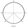
- Figure 6 shows a circle divided into arc degree segments and the approximate distribution angles for the inside of the pipe and the exterior of the pipe for the dispensing of the Bentonite lubricant.
- the outside of the pipe has lubricant distributed from 225 degrees to 135 degrees.
- the inside of the pipe casing has lubricant dispensed from 135 degrees to 225 degrees. Dispensing of the lubricant both on the inside and the outside is dependent upon the number of ports or openings in the outside spacer 62 and the inside spacer 68.
- a cutting head 20 is used for cutting through the earth and can include a ground lubrication dispenser shoe.
- the cutting head 50 is attached to the first lead pipe casing and is used to begin cutting and forming a tunnel. Lubrication if necessary helps break the friction of the soil both inside and outside the cutting head and the pipe casing.
- the head 50 is tubular in shape, and is blade edged at the annexed rim where initial contact is made with the ground during driving.
- An outer shoe is angled around outer perimeter of the cutting head.
- the outer shoe includes dispensing openings.
- the inner shoe angled to reduce friction through the earth for a low physical height profile.
- the inner shoe dispensing openings extends approximately from the four o'clock position to the eight o'clock position when looking directly at the head.
- the inner dispensing shoe and the outer dispensing shoe are preferably welded onto the cutting head.
- the dispensing pressure of the bentonite lubricant is preferably approximately 413 ⁇ 685KPa (60 pounds per square inch) and the pressure is preferably adjustable.
- conduits for a lubricant such as bentonite.
- One conduit is for outside dispensing and the other for inside dispensing.
- the bentonite or its equivalent is pumped into the shoes and around the head through the two separate circuits.
- the bentonite is of a wallpaper paste consistency.
- the attachment to the pipe casing is preferred to be a saddle for the conduit on the outside and inside of the pipe section. It is also preferred that the conduits are welded in place.
- the conduits are preferred to be attached to each other in series as pipe casings are added, and attached to the dispensing shoes on the cutting head.
- a plug of soil is formed.
- a plug of soil retention material is placed in the casing pipe behind the cutting head and before the hammer begins operation.
- the soil does not easily fall back in repose as it naturally would, thereby causing undesirable inflow of soil at the point of entry of the installation trench, thus causing unwanted settlement of the surface.
- the plug comprises flowable fill material.
- equipment such as tunnel digging machinery as shown in the attached drawings is used to excavate the soil in the tubing.
- a preparation area for the hammer especially where the conduit is to be installed at least partly underground.
- a pit surrounded by steel plates as shown in the attached figures may be placed around the hammer of the invention.
Landscapes
- Engineering & Computer Science (AREA)
- Mining & Mineral Resources (AREA)
- Life Sciences & Earth Sciences (AREA)
- Geology (AREA)
- Environmental & Geological Engineering (AREA)
- General Life Sciences & Earth Sciences (AREA)
- Geochemistry & Mineralogy (AREA)
- General Engineering & Computer Science (AREA)
- Mechanical Engineering (AREA)
- Physics & Mathematics (AREA)
- Fluid Mechanics (AREA)
- Earth Drilling (AREA)
- Excavating Of Shafts Or Tunnels (AREA)
- Placing Or Removing Of Piles Or Sheet Piles, Or Accessories Thereof (AREA)
- Supports For Pipes And Cables (AREA)
- Feeding And Watering For Cattle Raising And Animal Husbandry (AREA)
Claims (20)
- Verfahren zum Herstellen eines grabenlosen Tunnels für Rohrleitungen sehr großen Durchmessers mit Hilfe eines Futterrohrs eines Durchmessers größer als 1,829 m (72 Zoll), wobei mit dem Verfahren wenigstens 30,48 m (100 Fuß) des Futterrohrs installiert werden können, enthaltend folgende Schritte:a. Erstellen eines Schachtes im wesentlichen horizontal vor der Stelle, an der das Futterrohr (18, 110) installiert werden soll;b. Horizontales Anordnen eines großen Pfahlrammhammers (118) innerhalb des Schachtes;c. Anbringen eines ersten Abschnittes des Futterrohrs mit einem Durchmesser von wenigstens 1,829 m (72 Zoll) der Länge nach an einer Haube (14) und Anbringen der Haube am Rammende des Pfahlrammhammers, wobei der Hammer ein Hammer für hohe Aufschlagsenergie ist, die 81,349 kJ (60.000 Fuß-Pfund) überschreitet;d. Bereitstellen eines Ambosses (46) zwischen dem Pfahlrammhammer (118) und dem Futterrohrabschnitt;e. Anbringen eines Schneidkopfes (20) an einem Ende des Futterrohrs, das in die Erde getrieben werden soll;f. Aufwenden einer konstanten Spannung, um das Hammergehäuse (112) fest am Amboss angebracht zu halten;g. Vortreiben des ersten Abschnittes des Futterrohrs, an dessen einem Ende die Schneidkante angebracht ist, bis ein ausreichender Umfang des ersten Futterrohrabschnittes in der Erde eingebettet ist;h. Anbringen nachfolgender Futterrohre am ersten Futterrohr, wodurch ein Futterrohrtunnel von miteinander verbundenen Futterrohrabschnitten, die 30,48 m (100 Fuß) überschreiten, in der Erde erzeugt wird.
- Verfahren nach Anspruch 1, bei dem die konstante Spannung aus Schritt f durch ein Spannungsdämpfungssystem für den Pfahlrammhammer (118) erzeugt wird, um die Energie des Rückstoßes während des Pfahlrammens des Futterrohrabschnittes zu dämpfen.
- Verfahren nach Anspruch 3, bei dem das Spannungsdämpfungssystem weiterhin ein Seilrollensystem enthält, das eine Vielzahl von Seilrollen (26, 28, 31, 32) enthält.
- Verfahren nach Anspruch 3, bei dem die Rückseite des Hammers mit einer Spannkonsole (30a) versehen ist, die die Seilrollen und Stoßdämpfer (30) enthält.
- Verfahren nach Anspruch 3 oder 4, bei dem wenigstens zwei Seilrollen (26, 28) in der Erde an Pfählen (34, 34a) angebracht werden.
- Verfahren nach Anspruch 3, 4 oder 5, bei dem das Seilrollensystem zudem ein Spannseil (24) und eine Seilwinde (22) an einem Ende des Spannseils enthält.
- Verfahren nach Anspruch 6, bei dem das andere Ende des Spannseils mit einer Kraftmesszelle (22) versehen ist, um eine konstante Spannung im Seilrollensystem beizubehalten.
- Verfahren nach Anspruch 7, bei dem die Kraftmesszelle eine programmierbare Logiksteuereinheit (PLC) zum Steuern der Seilwinde (22) hat.
- Verfahren nach Anspruch 1, enthaltend folgende Schritte:a. Bereitstellen eines ersten Schmiermittel-Verteilungssystems (52) am ersten Rohrabschnitt auf der Außenseite des Futterrohrs in einem bestimmten Bogenmaß, um die äußere Erdreibung auf dem Futterrohr während das Hämmerns zu verringern; undb. Bereitstellen eines zweiten Schmiermittel-Verteilungssystems (54), das innerhalb des ersten Futterrohrabschnittes angebracht ist, um ein Schmiermittel um die Innenseite des Rohres in Übereinstimmung mit einem speziellen Bogen der Verteilung zu verteilen und so die Reibung auf der Innenseite des Futterrohrs, das vorgetrieben wird, zu verringern.
- Verfahren nach Anspruch 9, bei dem der Amboss (46) einen vorbestimmten Durchmesser ab dem Eingriff des vorzutreibenden Futterrohrabschnittes hat und der Hammer (118) einen Ambossdurchmesserabschnitt hat, der so eingestellt werden kann, dass Rohre unterschiedlichen Durchmessers während des Vortreibens aufgenommen werden.
- System zum Auslegen eines grabenlosen Tunnels in der Erde, das große Futterrohre, die im Durchmesser 1,829 m (72 Zoll) überschreiten, für eine Distanz verwenden kann, die 30,48 m (100 Fuß) überschreitet, enthaltend:a. einen Hochleistungs-Pfahlrammhammer (118), der wenigstens 81,349 kJ (60.000 Fuß-Pfund) Treibkraft aufwenden kann;b. eine Einrichtung (22, 22a, 26, 28, 32, 34, 34a) zum Erzeugen einer konstanten Spannung am Hammer und einen Amboss (46) zum Einstellen des Rückstoßes des Hammers, wenn ein Futterrohrabschnitt vorgetrieben wird;c. eine Haube (14), deren Durchmesser so bemessen ist, dass sie mit einem Ende eines Rohrabschnittes, das in Verbindung mit einer Platte vorgetrieben werden soll, und dem anderen Ende in Eingriff gelangt, das am Hammer angebracht ist;d. eine röhrenförmige Leitung (20), die einen messerähnlichen vorderen Rand zum Schneiden durch die Erde aufweist, im Durchmesser so bemessen, dass er am ersten Abschnitt des Futterrohrs angebracht wird, das vorgetrieben werden soll, um wirkungsvoll durch die Erde zu schneiden;e. wobei der Hochleistungshammer (118) verwendet wird, um aufeinander folgende Abschnitte des Futterrohrs, die miteinander verbunden sind, in Verbindung mit dem Schneidrand horizontal durch die Erde über Distanzen, die 30,48 m (100 Fuß) überschreiten, mit Hilfe der Futterrohre vorzutreiben, die einen Durchmesser haben, der 1,829 m (72 Zoll) überschreitet.
- System nach Anspruch 11, bei dem die Einrichtung zum Erzeugen einer konstanten Spannung ein Spannungsdämpfungssystem für den Pfahlrammhammer enthält, um die Energie des Rückstoßes während des Pfahltreibens des Futterrohrbschnittes zu dämpfen.
- System nach Anspruch 12, bei dem das Spannungsdämpfungssystem weiterhin ein Seilrollensystem enthält, das mehrere Seilrollen (26, 28, 31, 32) umfasst.
- System nach Anspruch 13, bei dem die Rückseite des Hammers mit einer Spannkonsole (30a) versehen ist, die die Seilrollen und Stoßdämpfer (30) enthält.
- System nach Anspruch 13 oder 14, bei dem wenigstens zwei Seilrollen (26, 28) in der Erde an Pfählen (34, 34a) angebracht werden.
- System nach Anspruch 13, 14 oder 15, bei dem das Seilrollensystem zudem ein Spannseil (24) und eine Seilwinde (22) an einem Ende des Spannseils enthält.
- System nach Anspruch 16, bei dem das andere Ende des Spannseils mit einer Kraftmesszelle (22) versehen ist, um eine konstante Spannung im Seilrollensystem beizubehalten.
- System nach Anspruch 17, bei dem die Kraftmesszelle eine programmierbare Logiksteuereinheit (PLC) zum Steuern der Seilwinde (22) hat.
- System zum Auslegen eines grabenlosen Tunnels nach Anspruch 11, enthaltend:a. eine Einrichtung (52, 54), die am Schneidkopf angebracht ist und ein Schmiermittel auf der Außenseite des Futterrohrs und auf der Innenseite des Futterrohrs gemäß einem vorbestimmten Schmiermittel-Verteilungsmuster auf der Außenseite des Futterrohrs und auf der Innenseite des Futterrohrs verteilt, um die Reibung auf dem Futterrohr während des Hammervorgangs zu verringern.
- System zum Auslegen eines grabenlosen Tunnels nach Anspruch 11, enthaltend:a. die Haube, die ein mit einem Flansch versehenes konisches Ende enthält, das eine Einrichtung zum Einstellen der Größe des Durchmessers der Haube (40) aufweist, um Rohre unterschiedlichen Durchmessers aufzunehmen, ohne dass eine separate einzelne Haube (40) für jede unterschiedliche Größe des Futterrohrdurchmessers erforderlich ist, und einen inneren Kanal enthält, der den Pfahlrammhammer aufnimmt, um die Länge eines Anfangsschachtes zu verringern, der erforderlich ist, um den Pfahlrammhammer (118) aufzunehmen.
Applications Claiming Priority (3)
| Application Number | Priority Date | Filing Date | Title |
|---|---|---|---|
| US10/065,682 US6652190B1 (en) | 2002-11-08 | 2002-11-08 | Method to install underground pipe casing |
| US65682 | 2002-11-08 | ||
| PCT/US2003/006565 WO2004044381A1 (en) | 2002-11-08 | 2003-03-03 | Method to install underground pipe casing |
Publications (3)
| Publication Number | Publication Date |
|---|---|
| EP1567747A1 EP1567747A1 (de) | 2005-08-31 |
| EP1567747A4 EP1567747A4 (de) | 2006-05-31 |
| EP1567747B1 true EP1567747B1 (de) | 2008-08-20 |
Family
ID=29581874
Family Applications (1)
| Application Number | Title | Priority Date | Filing Date |
|---|---|---|---|
| EP03711396A Expired - Lifetime EP1567747B1 (de) | 2002-11-08 | 2003-03-03 | Verfahren zur installation eines unterirdischen futterrohrs |
Country Status (11)
| Country | Link |
|---|---|
| US (1) | US6652190B1 (de) |
| EP (1) | EP1567747B1 (de) |
| KR (1) | KR20050086448A (de) |
| CN (1) | CN100523435C (de) |
| AT (1) | ATE405726T1 (de) |
| AU (1) | AU2003213708B2 (de) |
| CA (1) | CA2504950A1 (de) |
| DE (1) | DE60323131D1 (de) |
| MX (1) | MXPA05004914A (de) |
| WO (1) | WO2004044381A1 (de) |
| ZA (1) | ZA200503685B (de) |
Families Citing this family (13)
| Publication number | Priority date | Publication date | Assignee | Title |
|---|---|---|---|---|
| NL1031391C2 (nl) * | 2006-03-16 | 2007-09-18 | Sterk Midden Nederland B V | Werkwijze voor het vervaardigen van een doorgang in een ondergrond, alsmede pijpsectie daarvoor. |
| RU2347037C2 (ru) * | 2007-04-09 | 2009-02-20 | ГОУ ВПО "Санкт-Петербургский государственный архитектурно-строительный университет" | Гидравлический молот для погружения свай |
| US8540458B2 (en) | 2011-06-14 | 2013-09-24 | Roodle, Inc. | Center hole ram cable puller |
| CN103353045B (zh) * | 2013-07-08 | 2014-06-18 | 江苏锐成机械有限公司 | 重层式管路再生化工法及其结构 |
| RU2552266C1 (ru) * | 2014-04-17 | 2015-06-10 | федеральное государственное бюджетное образовательное учреждение высшего профессионального образования "Волгоградский государственный архитектурно-строительный университет" (ВолгГАСУ) | Центрирующий элемент для пропуска пневмоопалубки к пневмотрубоукладчику |
| WO2016102946A1 (en) * | 2014-12-22 | 2016-06-30 | James Crawford Thomson | Method and apparatus for forming tunnels for transport routes |
| CA2891805C (en) * | 2015-05-15 | 2020-07-14 | Tcg Tunneling Company Inc. | Pipe ramming system with hydraulic crowd |
| PL3752702T3 (pl) | 2018-02-13 | 2023-05-08 | Arcbyt, Inc. | Systemy i sposoby do instalacji rur podziemnych |
| US10954645B2 (en) * | 2019-08-23 | 2021-03-23 | Christopher DeBlauw | System and apparatus for driving piles |
| CA3158674A1 (en) | 2022-05-11 | 2023-11-11 | The Tunneling Company Inc. | Method and apparatus for trenchless extraction of pipe |
| WO2024059454A1 (en) | 2022-09-15 | 2024-03-21 | Arcbyt, Inc. | Multi-tool boring systems and methods of operating such systems |
| CN116734816B (zh) * | 2023-08-15 | 2023-12-26 | 中交天津港湾工程研究院有限公司 | 一种螺旋排土微型管幕顶管的实时偏移量监测方法 |
| CN117419218B (zh) * | 2023-10-18 | 2024-06-25 | 中建四局安装工程有限公司 | 一种预制管在竖井内的安装方法 |
Family Cites Families (12)
| Publication number | Priority date | Publication date | Assignee | Title |
|---|---|---|---|---|
| DE7035606U (de) * | 1970-09-25 | 1971-02-18 | Weiss Bruno | Vorrichtung zum vorpressen von rohren, insbesondere fuer die herstellung von rohrdecken beim u-bahnbau. |
| NL7704561A (en) * | 1977-04-26 | 1978-10-30 | Koninkl Nederhorst Bouw B V | Pile driving cap with elastic buffer - has thin buffer between tapering tubes on common lengthwise axis |
| CA1046294A (en) * | 1977-06-13 | 1979-01-16 | Roger Woods | Method and apparatus for lateral excavation |
| US4557627A (en) * | 1979-05-24 | 1985-12-10 | Locher & Cie AGZZ | Apparatus and method for tunnel construction with shield drive |
| GB2101656B (en) * | 1981-07-15 | 1984-12-05 | Trest Orgtekhstroi Glavnovosib | Trenchless pipe laying |
| CN1007635B (zh) * | 1985-04-01 | 1990-04-18 | 田善达 | 地下土层通行器 |
| DE3734998A1 (de) * | 1987-10-16 | 1989-04-27 | Schmidt Paul | Rammvorrichtung |
| JPH01219293A (ja) * | 1988-02-26 | 1989-09-01 | Matsuzaka Boeki Kk | 鋼管の打撃推進工法における方向修正方法およびその装置 |
| CA2070417A1 (en) * | 1989-10-25 | 1991-04-26 | Valto Ilomaki | Method for the mounting of underground pipelines |
| US5632575A (en) * | 1994-08-30 | 1997-05-27 | Lorenzen; Frank J. | Method and apparatus for controlled pumping of bentonite around a pipe jacked tunnel |
| US6109832A (en) * | 1998-04-02 | 2000-08-29 | Lincoln; David A. | Ram burster and method for installing tubular casing underground |
| US6357967B1 (en) * | 2000-05-01 | 2002-03-19 | Samuel W. Putnam | Apparatus for bursting and replacing pipe |
-
2002
- 2002-11-08 US US10/065,682 patent/US6652190B1/en not_active Expired - Fee Related
-
2003
- 2003-03-03 MX MXPA05004914A patent/MXPA05004914A/es not_active IP Right Cessation
- 2003-03-03 CA CA002504950A patent/CA2504950A1/en not_active Abandoned
- 2003-03-03 AT AT03711396T patent/ATE405726T1/de not_active IP Right Cessation
- 2003-03-03 AU AU2003213708A patent/AU2003213708B2/en not_active Ceased
- 2003-03-03 DE DE60323131T patent/DE60323131D1/de not_active Expired - Fee Related
- 2003-03-03 WO PCT/US2003/006565 patent/WO2004044381A1/en not_active Ceased
- 2003-03-03 CN CNB038257831A patent/CN100523435C/zh not_active Expired - Fee Related
- 2003-03-03 EP EP03711396A patent/EP1567747B1/de not_active Expired - Lifetime
- 2003-03-03 KR KR1020057008226A patent/KR20050086448A/ko not_active Ceased
-
2005
- 2005-05-09 ZA ZA200503685A patent/ZA200503685B/en unknown
Also Published As
| Publication number | Publication date |
|---|---|
| CA2504950A1 (en) | 2004-05-27 |
| MXPA05004914A (es) | 2005-11-17 |
| KR20050086448A (ko) | 2005-08-30 |
| AU2003213708B2 (en) | 2009-08-20 |
| AU2003213708A1 (en) | 2004-06-03 |
| CN1723335A (zh) | 2006-01-18 |
| DE60323131D1 (de) | 2008-10-02 |
| WO2004044381A1 (en) | 2004-05-27 |
| EP1567747A1 (de) | 2005-08-31 |
| EP1567747A4 (de) | 2006-05-31 |
| US6652190B1 (en) | 2003-11-25 |
| ATE405726T1 (de) | 2008-09-15 |
| CN100523435C (zh) | 2009-08-05 |
| ZA200503685B (en) | 2006-08-30 |
Similar Documents
| Publication | Publication Date | Title |
|---|---|---|
| EP1567747B1 (de) | Verfahren zur installation eines unterirdischen futterrohrs | |
| JPH0157239B2 (de) | ||
| CN108916469A (zh) | 小口径管道连续作业的施工方法 | |
| KR102002526B1 (ko) | 수직구 굴착시스템 및 이를 이용한 수직구 시공방법 | |
| CN108643193B (zh) | 一种基坑支护预应力锚索钻凿起拔方法 | |
| KR101368999B1 (ko) | 관거매설공의 보강이 가능한 관거 추진장치 및 이를 이용한 관거 시공 공법 | |
| US4102413A (en) | Rock drilling apparatus and method | |
| Simicevic et al. | Guidelines for pipe ramming | |
| CN111894449B (zh) | 用于山地丘陵地带塔基桩孔施工的便携注水式旋挖设备 | |
| CN111101865B (zh) | 一种高效率钻孔设备 | |
| CN110144903B (zh) | 一种基坑支护遇防空洞的施工工法 | |
| RU2156847C2 (ru) | Способ образования горизонтальных скважин | |
| RU133543U1 (ru) | Буровая установка для прокладки трубопроводов в обводненных грунтах | |
| JP3996162B2 (ja) | 推進管の坑内推進基地及びその構築方法 | |
| Committee on Construction Equipment and Techniques | Trenchless excavation construction methods: classification and evaluation | |
| KR200368544Y1 (ko) | 지하구조물 구축을 위한 수평관 압입장치 | |
| Howell | The pipe ramming technique | |
| Kramer et al. | Pipe jacking and microtunnelling | |
| CN117988873A (zh) | 一种管幕下土方开挖支撑方法及装置 | |
| CN203403401U (zh) | 一种易拆卸回收的新型桩 | |
| Carter et al. | Trenchless Technology Success Story: Pipe Ramming | |
| Paone et al. | Horizontal boring technology: a state-of-the-art study | |
| JP5613807B1 (ja) | 管路敷設方法、及び管路敷設方法に使用される保護管、閉塞部材 | |
| CN117514189A (zh) | 一种小直径顶管在硬岩层中的掘进方法 | |
| Thomson | Pipejacking and microtunnelling methods |
Legal Events
| Date | Code | Title | Description |
|---|---|---|---|
| PUAI | Public reference made under article 153(3) epc to a published international application that has entered the european phase |
Free format text: ORIGINAL CODE: 0009012 |
|
| 17P | Request for examination filed |
Effective date: 20050511 |
|
| AK | Designated contracting states |
Kind code of ref document: A1 Designated state(s): AT BE BG CH CY CZ DE DK EE ES FI FR GB GR HU IE IT LI LU MC NL PT RO SE SI SK TR |
|
| AX | Request for extension of the european patent |
Extension state: AL LT LV MK |
|
| DAX | Request for extension of the european patent (deleted) | ||
| A4 | Supplementary search report drawn up and despatched |
Effective date: 20060420 |
|
| RIC1 | Information provided on ipc code assigned before grant |
Ipc: F16L 1/036 20060101ALI20060412BHEP Ipc: E02D 13/10 20060101ALI20060412BHEP Ipc: E21D 9/04 20060101AFI20040529BHEP Ipc: E21B 7/20 20060101ALI20060412BHEP |
|
| 17Q | First examination report despatched |
Effective date: 20061009 |
|
| GRAP | Despatch of communication of intention to grant a patent |
Free format text: ORIGINAL CODE: EPIDOSNIGR1 |
|
| GRAS | Grant fee paid |
Free format text: ORIGINAL CODE: EPIDOSNIGR3 |
|
| GRAA | (expected) grant |
Free format text: ORIGINAL CODE: 0009210 |
|
| AK | Designated contracting states |
Kind code of ref document: B1 Designated state(s): AT BE BG CH CY CZ DE DK EE ES FI FR GB GR HU IE IT LI LU MC NL PT RO SE SI SK TR |
|
| REG | Reference to a national code |
Ref country code: GB Ref legal event code: FG4D |
|
| REG | Reference to a national code |
Ref country code: CH Ref legal event code: EP |
|
| REG | Reference to a national code |
Ref country code: IE Ref legal event code: FG4D |
|
| REF | Corresponds to: |
Ref document number: 60323131 Country of ref document: DE Date of ref document: 20081002 Kind code of ref document: P |
|
| PG25 | Lapsed in a contracting state [announced via postgrant information from national office to epo] |
Ref country code: ES Free format text: LAPSE BECAUSE OF FAILURE TO SUBMIT A TRANSLATION OF THE DESCRIPTION OR TO PAY THE FEE WITHIN THE PRESCRIBED TIME-LIMIT Effective date: 20081201 Ref country code: NL Free format text: LAPSE BECAUSE OF FAILURE TO SUBMIT A TRANSLATION OF THE DESCRIPTION OR TO PAY THE FEE WITHIN THE PRESCRIBED TIME-LIMIT Effective date: 20080820 |
|
| PG25 | Lapsed in a contracting state [announced via postgrant information from national office to epo] |
Ref country code: SI Free format text: LAPSE BECAUSE OF FAILURE TO SUBMIT A TRANSLATION OF THE DESCRIPTION OR TO PAY THE FEE WITHIN THE PRESCRIBED TIME-LIMIT Effective date: 20080820 Ref country code: FI Free format text: LAPSE BECAUSE OF FAILURE TO SUBMIT A TRANSLATION OF THE DESCRIPTION OR TO PAY THE FEE WITHIN THE PRESCRIBED TIME-LIMIT Effective date: 20080820 Ref country code: AT Free format text: LAPSE BECAUSE OF FAILURE TO SUBMIT A TRANSLATION OF THE DESCRIPTION OR TO PAY THE FEE WITHIN THE PRESCRIBED TIME-LIMIT Effective date: 20080820 |
|
| PG25 | Lapsed in a contracting state [announced via postgrant information from national office to epo] |
Ref country code: BE Free format text: LAPSE BECAUSE OF FAILURE TO SUBMIT A TRANSLATION OF THE DESCRIPTION OR TO PAY THE FEE WITHIN THE PRESCRIBED TIME-LIMIT Effective date: 20080820 |
|
| PG25 | Lapsed in a contracting state [announced via postgrant information from national office to epo] |
Ref country code: BG Free format text: LAPSE BECAUSE OF FAILURE TO SUBMIT A TRANSLATION OF THE DESCRIPTION OR TO PAY THE FEE WITHIN THE PRESCRIBED TIME-LIMIT Effective date: 20081120 Ref country code: DK Free format text: LAPSE BECAUSE OF FAILURE TO SUBMIT A TRANSLATION OF THE DESCRIPTION OR TO PAY THE FEE WITHIN THE PRESCRIBED TIME-LIMIT Effective date: 20080820 |
|
| PG25 | Lapsed in a contracting state [announced via postgrant information from national office to epo] |
Ref country code: PT Free format text: LAPSE BECAUSE OF FAILURE TO SUBMIT A TRANSLATION OF THE DESCRIPTION OR TO PAY THE FEE WITHIN THE PRESCRIBED TIME-LIMIT Effective date: 20090120 Ref country code: CZ Free format text: LAPSE BECAUSE OF FAILURE TO SUBMIT A TRANSLATION OF THE DESCRIPTION OR TO PAY THE FEE WITHIN THE PRESCRIBED TIME-LIMIT Effective date: 20080820 Ref country code: RO Free format text: LAPSE BECAUSE OF FAILURE TO SUBMIT A TRANSLATION OF THE DESCRIPTION OR TO PAY THE FEE WITHIN THE PRESCRIBED TIME-LIMIT Effective date: 20080820 Ref country code: SK Free format text: LAPSE BECAUSE OF FAILURE TO SUBMIT A TRANSLATION OF THE DESCRIPTION OR TO PAY THE FEE WITHIN THE PRESCRIBED TIME-LIMIT Effective date: 20080820 |
|
| PLBE | No opposition filed within time limit |
Free format text: ORIGINAL CODE: 0009261 |
|
| STAA | Information on the status of an ep patent application or granted ep patent |
Free format text: STATUS: NO OPPOSITION FILED WITHIN TIME LIMIT |
|
| 26N | No opposition filed |
Effective date: 20090525 |
|
| PG25 | Lapsed in a contracting state [announced via postgrant information from national office to epo] |
Ref country code: EE Free format text: LAPSE BECAUSE OF FAILURE TO SUBMIT A TRANSLATION OF THE DESCRIPTION OR TO PAY THE FEE WITHIN THE PRESCRIBED TIME-LIMIT Effective date: 20080820 |
|
| PG25 | Lapsed in a contracting state [announced via postgrant information from national office to epo] |
Ref country code: IT Free format text: LAPSE BECAUSE OF FAILURE TO SUBMIT A TRANSLATION OF THE DESCRIPTION OR TO PAY THE FEE WITHIN THE PRESCRIBED TIME-LIMIT Effective date: 20080820 |
|
| PG25 | Lapsed in a contracting state [announced via postgrant information from national office to epo] |
Ref country code: MC Free format text: LAPSE BECAUSE OF NON-PAYMENT OF DUE FEES Effective date: 20090331 |
|
| REG | Reference to a national code |
Ref country code: CH Ref legal event code: PL |
|
| GBPC | Gb: european patent ceased through non-payment of renewal fee |
Effective date: 20090303 |
|
| REG | Reference to a national code |
Ref country code: FR Ref legal event code: ST Effective date: 20091130 |
|
| REG | Reference to a national code |
Ref country code: IE Ref legal event code: MM4A |
|
| PG25 | Lapsed in a contracting state [announced via postgrant information from national office to epo] |
Ref country code: SE Free format text: LAPSE BECAUSE OF FAILURE TO SUBMIT A TRANSLATION OF THE DESCRIPTION OR TO PAY THE FEE WITHIN THE PRESCRIBED TIME-LIMIT Effective date: 20081120 Ref country code: LI Free format text: LAPSE BECAUSE OF NON-PAYMENT OF DUE FEES Effective date: 20090331 Ref country code: IE Free format text: LAPSE BECAUSE OF NON-PAYMENT OF DUE FEES Effective date: 20090303 Ref country code: DE Free format text: LAPSE BECAUSE OF NON-PAYMENT OF DUE FEES Effective date: 20091001 Ref country code: CH Free format text: LAPSE BECAUSE OF NON-PAYMENT OF DUE FEES Effective date: 20090331 |
|
| PG25 | Lapsed in a contracting state [announced via postgrant information from national office to epo] |
Ref country code: FR Free format text: LAPSE BECAUSE OF NON-PAYMENT OF DUE FEES Effective date: 20091123 Ref country code: GB Free format text: LAPSE BECAUSE OF NON-PAYMENT OF DUE FEES Effective date: 20090303 |
|
| PG25 | Lapsed in a contracting state [announced via postgrant information from national office to epo] |
Ref country code: GR Free format text: LAPSE BECAUSE OF FAILURE TO SUBMIT A TRANSLATION OF THE DESCRIPTION OR TO PAY THE FEE WITHIN THE PRESCRIBED TIME-LIMIT Effective date: 20081121 |
|
| PG25 | Lapsed in a contracting state [announced via postgrant information from national office to epo] |
Ref country code: LU Free format text: LAPSE BECAUSE OF NON-PAYMENT OF DUE FEES Effective date: 20090303 |
|
| PG25 | Lapsed in a contracting state [announced via postgrant information from national office to epo] |
Ref country code: HU Free format text: LAPSE BECAUSE OF FAILURE TO SUBMIT A TRANSLATION OF THE DESCRIPTION OR TO PAY THE FEE WITHIN THE PRESCRIBED TIME-LIMIT Effective date: 20090221 |
|
| PG25 | Lapsed in a contracting state [announced via postgrant information from national office to epo] |
Ref country code: TR Free format text: LAPSE BECAUSE OF FAILURE TO SUBMIT A TRANSLATION OF THE DESCRIPTION OR TO PAY THE FEE WITHIN THE PRESCRIBED TIME-LIMIT Effective date: 20080820 |
|
| PG25 | Lapsed in a contracting state [announced via postgrant information from national office to epo] |
Ref country code: CY Free format text: LAPSE BECAUSE OF FAILURE TO SUBMIT A TRANSLATION OF THE DESCRIPTION OR TO PAY THE FEE WITHIN THE PRESCRIBED TIME-LIMIT Effective date: 20080820 |