EP1567743B1 - Eckverbindungsvorrichtung für fenster- oder türprofilrahmen - Google Patents
Eckverbindungsvorrichtung für fenster- oder türprofilrahmen Download PDFInfo
- Publication number
- EP1567743B1 EP1567743B1 EP03751064A EP03751064A EP1567743B1 EP 1567743 B1 EP1567743 B1 EP 1567743B1 EP 03751064 A EP03751064 A EP 03751064A EP 03751064 A EP03751064 A EP 03751064A EP 1567743 B1 EP1567743 B1 EP 1567743B1
- Authority
- EP
- European Patent Office
- Prior art keywords
- joint
- profile members
- mobile portion
- hollow profile
- sheet metal
- Prior art date
- Legal status (The legal status is an assumption and is not a legal conclusion. Google has not performed a legal analysis and makes no representation as to the accuracy of the status listed.)
- Expired - Lifetime
Links
- 229910052751 metal Inorganic materials 0.000 claims abstract description 55
- 239000002184 metal Substances 0.000 claims abstract description 55
- 238000007373 indentation Methods 0.000 claims abstract description 16
- 238000000034 method Methods 0.000 claims abstract description 11
- 230000000694 effects Effects 0.000 claims abstract description 7
- 239000000463 material Substances 0.000 claims description 4
- 229910000831 Steel Inorganic materials 0.000 claims description 2
- 239000010959 steel Substances 0.000 claims description 2
- 229910000838 Al alloy Inorganic materials 0.000 description 2
- 230000001154 acute effect Effects 0.000 description 2
- 239000004411 aluminium Substances 0.000 description 2
- 229910052782 aluminium Inorganic materials 0.000 description 2
- XAGFODPZIPBFFR-UHFFFAOYSA-N aluminium Chemical compound [Al] XAGFODPZIPBFFR-UHFFFAOYSA-N 0.000 description 2
- 230000015572 biosynthetic process Effects 0.000 description 2
- 238000005553 drilling Methods 0.000 description 2
- 239000004033 plastic Substances 0.000 description 2
- 229920003023 plastic Polymers 0.000 description 2
- 238000010276 construction Methods 0.000 description 1
- 238000005520 cutting process Methods 0.000 description 1
- 230000008030 elimination Effects 0.000 description 1
- 238000003379 elimination reaction Methods 0.000 description 1
- 238000007730 finishing process Methods 0.000 description 1
- 239000011521 glass Substances 0.000 description 1
- 238000009434 installation Methods 0.000 description 1
- 238000004519 manufacturing process Methods 0.000 description 1
- 210000005036 nerve Anatomy 0.000 description 1
- 238000004806 packaging method and process Methods 0.000 description 1
- 238000006467 substitution reaction Methods 0.000 description 1
Images


Classifications
-
- E—FIXED CONSTRUCTIONS
- E06—DOORS, WINDOWS, SHUTTERS, OR ROLLER BLINDS IN GENERAL; LADDERS
- E06B—FIXED OR MOVABLE CLOSURES FOR OPENINGS IN BUILDINGS, VEHICLES, FENCES OR LIKE ENCLOSURES IN GENERAL, e.g. DOORS, WINDOWS, BLINDS, GATES
- E06B3/00—Window sashes, door leaves, or like elements for closing wall or like openings; Layout of fixed or moving closures, e.g. windows in wall or like openings; Features of rigidly-mounted outer frames relating to the mounting of wing frames
- E06B3/96—Corner joints or edge joints for windows, doors, or the like frames or wings
- E06B3/964—Corner joints or edge joints for windows, doors, or the like frames or wings using separate connection pieces, e.g. T-connection pieces
- E06B3/968—Corner joints or edge joints for windows, doors, or the like frames or wings using separate connection pieces, e.g. T-connection pieces characterised by the way the connecting pieces are fixed in or on the frame members
- E06B3/98—Corner joints or edge joints for windows, doors, or the like frames or wings using separate connection pieces, e.g. T-connection pieces characterised by the way the connecting pieces are fixed in or on the frame members the connecting pieces being specially adapted for drawing the frame members towards each other
- E06B3/982—Mitre joints
-
- E—FIXED CONSTRUCTIONS
- E06—DOORS, WINDOWS, SHUTTERS, OR ROLLER BLINDS IN GENERAL; LADDERS
- E06B—FIXED OR MOVABLE CLOSURES FOR OPENINGS IN BUILDINGS, VEHICLES, FENCES OR LIKE ENCLOSURES IN GENERAL, e.g. DOORS, WINDOWS, BLINDS, GATES
- E06B3/00—Window sashes, door leaves, or like elements for closing wall or like openings; Layout of fixed or moving closures, e.g. windows in wall or like openings; Features of rigidly-mounted outer frames relating to the mounting of wing frames
- E06B3/96—Corner joints or edge joints for windows, doors, or the like frames or wings
- E06B3/964—Corner joints or edge joints for windows, doors, or the like frames or wings using separate connection pieces, e.g. T-connection pieces
- E06B3/968—Corner joints or edge joints for windows, doors, or the like frames or wings using separate connection pieces, e.g. T-connection pieces characterised by the way the connecting pieces are fixed in or on the frame members
- E06B3/9681—Corner joints or edge joints for windows, doors, or the like frames or wings using separate connection pieces, e.g. T-connection pieces characterised by the way the connecting pieces are fixed in or on the frame members by press fit or adhesion
- E06B3/9682—Mitre joints
Definitions
- the invention relates to an angular joint employed in the process of angular connections of hollow profiles, such as in the orthogonal connections of profiles being previously cut at 45° and coming to contact to form parallelepipedal frames for doors or windows.
- Joints for door and window profile frames of the prior art of the type of spring activated button means removably engaging into suitable apertures of the profiles to stabilize the angular connection thereof, require, prior to employment thereof, the opening of apertures at precisely selected locations of the profiles wherein are removably engaged the abovementioned spring activated buttons.
- This process is awkward and time consuming due to the accuracy required in marking and drilling of the apertures and often leads to an imperfect fit of the profiles and to a structure of reduced aesthetics and functionality due to the non-alignment of the profiles.
- EP 0 644 312 discloses a set-square connecting structure for right angle connections of profile frames for frames for doors and windows, wherein a pair of apertures is required in the profiles being brought for connection, for engagement of protruding teeth of the connecting structure into these apertures and the safe locking of the profile sections with one another.
- EP 0235 039 and FR 2 429 350 also disclose connecting devices for the assembly of tubular profiles for the formation of door/window frames, which function through the engagement of protruding buttons into correspondingly sized side apertures in the profiles being brought together for connection.
- WO 02/075093 and US- 6,042,298 also require the accurate opening of side apertures onto the profiles to be connected, and they further include a plurality of components that make the joint rather complex and of increased manufacturing and assembly cost.
- GB-2 072 296 discloses a joint wherein a clamping member is moved through a bolt being screwed along the line of matching contact of the profiles so that opposed hooks of the clamping member are drawn into engagement with punched depressions in the outside walls of the hollow sections being connected.
- US - 5, 109,645 discloses a symmetrical shaped metal angle piece with resilient end portions and sharp edged terminations, that slides freely on being entered within the hollow profile sections being connected, but thereafter locks into engaged, non withdrawable relation, due to the reversed attitude of the resilient end portions and their associated sharp edges.
- this joint is mainly directed to serve a permanent connection of the profiles, if disconnection of the frame is desired, one has to attempt, through slots in the profile walls, to pry inwardly the profiles and release them from jamming engagement.
- the object of the present invention is to provide for an angular joint of hollow metallic profile members being brought together for the formation of door or window frames and the like, said angular joint being simple in construction, easily assembled or disassembled and providing a self-aligned, rigid connection of the profile members.
- a further object of the invention is the elimination of the need for accurately marking and subsequently opening of side apertures onto the profile members being connected, thereby substantially facilitating and speeding up of the assembly process.
- Another object of the invention is to provide for alternative embodiments of the joint of the invention, adapting it to various applications extending beyond the field of orthogonal connections of hollow profile members being connected to form door and window frames and making the joint of the invention applicable in connections of profile members of any kind and at any angle whatsoever.
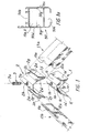
- the angular joint of the invention comprises a slide base portion 1 and a sheet metal mobile portion 2 superimposed thereupon, the sheet metal portion 2 including upwardly extending legs 2e with indenting edges 2g, a bolt 3 being employed in the tightening process of the joint, wherein after the joint has been inserted into the hollow profile members being brought together for connection, the bolt 3 acts so as to exert an upwardly raising force onto the sheet metal mobile portion 2, whilst maintaining base portion 1 at a fixed position, and subsequently leading the sharp indenting edges 2g of the sheet metal portion 1 to producing an indentation effect into the walls of the corresponding chambers 13a, 13b of the hollow profiles being angularly connected with the joint, as the joint is being tightened, thereby resulting in a robust, self aligned connection of the hollow profile members.
- the joint of the invention is particularly related with the assembly of frames that are being assembled from previously cut lengths of profiles e.g. aluminium or plastic profiles, such profiles having a hollow section to allow introduction and operation of the joint.
- a broad, but not exclusive, field of application of the invention is the connection of profile members in the corners thereof, when they are brought together to form generally parallelepipedal frames or casings for door and window applications.
- profile members are previously cut at 45° at the matching edges thereof to allow for an optimally aesthetic fit of the orthogonal connection.
- the joint of the invention has a necessarily orthogonal configuration in the particular application, it may equally well have the configuration of an acute or an oblique angle to serve applications wherein the hollow profile members are connected at an acute or an oblique angle respectively.
- the dimensions of the joint of the invention may naturally vary to make it compatible with different sizes and sections of profile members.
- FIG. 1a An illustrative hollow profile member 50 is shown in Fig. 1a , such profile member 50 comprising a pair of parallel walls 50c, 50d extending on the one hand at an open end 50a wherein is fitted the item that is being framed by such perimetrically covering length of the profile member, e.g. a glass or shutter panel for a door or window assembly, and on the other hand at and end 50b, opposite to the open end 50a, end 50b being fixedly mounted to the casing.
- a chamber 13a,b is formed in between 50a and 50b, such chamber serving for the introduction of the joint of the invention. Whilst other details of the profile members to be connected may vary, the chambers 13a,b are available for the employment of the joint of the invention.
- the drawings therefore depict the abstract detail of such rectangular chambers 13a and 13b with respective open ends 12a, 12b of the hollow profile members being brought together for connection.
- the joint of the invention shown in Fig.1 comprises a fixed slide base portion 1 and an elastically deformable sheet metal portion 2 superimposed onto the fixed slide base portion 1 and having a configuration that generally corresponds to the surface of the base portion 1 whereupon it is being seated.
- Both portions 1 and 2 are symmetrically arranged on either side of plane x-x' ( Fig. 2b ), a central bolt 3 with a screwing head end 3a and a sharp edge 3b also passing through the same plane of symmetry x-x' being driven by means of a screw driver 14, wherein this plane of symmetry x-x' coincides with the plane of contact of the two hollow profile members being brought together for connection.
- the fixed slide base portion 1 is an angular item with a pair of planar outer sides 1e forming an angle corresponding to the angle at which the profile members are being connected, at this instance an angle of 90°, a slight planar recession 1g being formed near the junction of these outer sides 1e, such planar recession 1g serving as a means of overcoming possible obstacles in the course of sliding of these outer sides 1e onto the walls of corresponding chambers 13a, 13b, that might be due to possible imperfections in the cutting and finishing process of the edges of the metal profile members being brought together for connection.
- the slide base portion 1 forms a flat basement portion 1a overlying the junction of the above outer sides 1e with a cavity 1b being centrally located thereupon to serve the purpose of receiving the sharp edge 3 b of bolt 3.
- the inner sides of the fixed slide base portion 1 extend to a pair of planar sections 1c which are substantially parallel to the walls of profile chambers 13a,b whereupon the outer planar sides 1e are seated and subsequently extend into convergent portions 1d terminating at symmetrically located edges 1f.
- the herein above described configuration of the sides of the fixed slide base portion 1 substantially improves the characteristics of the process of sliding of the sheet metal mobile portion 2 onto the fixed slide base portion 1 as will be explained hereinafter.
- the sheet metal mobile portion 2 has a configuration generally identical with the configuration of the slide base portion 1, with an upper basement 2a with a centrally located cavity 2b wherein is being driven the sharp edge 3b of the tightening bolt 3, wherein the upper basement 2a lies perpendicularly to the plane of symmetry x-x' and symmetrically above the basement 1a of the base portion 1.
- the upper basement 2a symmetrically extends to planar side surfaces 2c and 2d, each with a length generally equivalent to the length of underlying surfaces 1c, 1d of the base portion 1, whereupon they slide.
- the sheet metal mobile portion 2 is bent upwardly at the terminals 2f of side surfaces 2c-d at an angle (180- ⁇ )° as illustrated in Fig. 2c , and extends to upwardly extending sides 2e on either side thereof terminating at sharp edges 2g, such upwardly extending sides 2e thereby being oriented in a direction substantially parallel to the plane of symmetry x-x'.
- Figs. 7a-c are depicted possible alternative solutions for implementing such hole with internal threading.
- hole 2b is being formed by expansion of the sheet metal into a cylindrical collar 19 that is subsequently internally threaded.
- Fig. 7b is depicted an alternative solution of employment of an additional plate 18 having a planar surface 18a with dimensions such as to fit onto the basement 2a of the sheet metal portion 2 and a central hole 18b that is internally threaded and coincides with hole 2b on the basement 2a when plate 18 is brought in contact with basement 2a.
- Fig. 7c is depicted an additional internally threaded cylindrical collar 48 with a body portion 48a and a central hole 48b coinciding with hole 2b of the sheet metal portion 2.
- cavity 2b in the sheet metal portion 2 is drilled through and forms a thorough internally threaded hole, such hole being implemented in either one of the illustrative embodiments of Figs 7a-c , bolt 3 is driven through this hole 2b and terminates by contact of the sharp edge 3b thereof onto the cavity 1b being provided axially underneath hole 2b on the fixed slide base portion 1. Whilst this condition corresponds to the joint having been assembled but not tightened as shown in Fig. 2a , when as shown in Fig.
- Fig. 2c characteristically depicts a magnified view of a detail in the process of tightening of the joint of the invention.
- Fig. 2c characteristically depicts a magnified view of a detail in the process of tightening of the joint of the invention.
- Resilient stresses are thereby stored in sheet metal portion 2, uniformly applied on either side of the joint, such stresses thereby maintaining the joint in a tightened condition and the profile members rigidly connected
- a hole is drilled through the corresponding coaxial cavity 1b of the fixed slide base portion 1 as shown in Fig. 3 .
- the bolt 3 is then being driven from the inner junction of the profiles to be connected and sharp edge 3b thereof firmly contracts sheet metal portion 2 at cavity 2b thereof and exerts a raising force thereupon, eventually resulting in the indentation of the walls of the profiles to be connected by the sharp edges 2g of the upwardly extending sides 2e of the sheet metal mobile portion 2.
- the form of the sharp edges 2g of the upwardly extending sides 2e of the sheet metal mobile portion 2 is selected so as to render an optimum indentation effect.
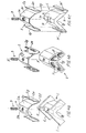
- they may for example have the toothed form depicted in Fig. 1 or Fig. 4a and Fig. 4b or they may take the double razor edge like form of edges 20g in the upwardly extending sides 20e of an alternative embodiment of the invention depicted in Figs 5, 5a , wherein the mobile portion 2 of the joint of the invention is made from a profile of hard aluminium alloy with an upper basement 20a provided with a centrally located hole 20b and sides 20c - 20d in sliding contract with corresponding sides of the underlying slide base portion 1.
- a single razor edge ending of upwardly extending sides 20e of the mobile portion 20 made from hard aluminium alloy may be equally effective in the indentation of the relatively softer walls of the hollow profiles to be connected, however the double razor edge like configuration further serves the purpose of a secure sequential indentation of the walls of the profile members.
- the upwardly extending legs 20e of the mobile portion 20 may form a recession, wherein an independent sheet metal plate 15, preferably with toothed edge configuration may be fitted to serve as an indentation means.
- legs 20e may extend to a plurality of pointed pins 20g'.
- the sheet metal portion 2 is alternatively made with side surfaces 2c ending at a bent structure of the sheet metal portion forming a recession 17 for the engagement of a wire 16, made from steel in the form of a II section in substitution of the otherwise planar sides 2d of the sheet metal portion 2, with the legs thereof bent to upwardly extending members with sharp edges 16g playing the role of profile wall indentation elements.
- the fixed base portion 1 may be made in two identical portions, symmetrically on either side of the plane of symmetry x-x', the two identical portions being pivotally connected around a pivotal axis 60 and thereby being appropriate for the connection of hollow profiles forming varying angles at the junction thereof.
- the sheet metal mobile portion 2 might under such circumstances also be adjustable to profile connections at varying angles with the pivotally mounted end portion 16 thereof.
- the fixed slide base portion 1 of the joint of the invention may also receive alternative forms.
- base portion 1 is provided with elevated end walls 6 with opposing central nerves 5 that fit into recessions 4 of the sheet metal mobile portion 2.
- base portion 1 does not terminate in the abovementioned terminals 1f, but is bent upwardly following a configuration similar to that of the sheet metal portion 2, so that the upwardly extending legs 2e of the latter may fit into the recessions being formed by the upwardly extending legs 1e' of the fixed slide base portion 1.
- the joint configuration depicted in Fig. 4a and preferably that of Fig. 4c serves as an advantageous embodiment, wherein the sheet metal mobile portion 2 fits tightly into slide base portion 1, so as to facilitate packaging of the joint and enable handling of the same as if it were a single item.
- Fig. 4b shows an alternative embodiment of the base portion 1 of the invention, which is more bulky and is applicable in cases of rather wide profile connections, wherein due to the bulk of the base portion 1, it is preferably made with perforations 7, in order to reduce material cost and weight of the item.
- Fig. 8a depicts an alternative embodiment of the joint of the invention, wherein the sheet metal portion 2 is made in two discrete, independent parts, whilst the single item of the base portion 1 further comprises flat plate extensions 1h perpendicularly located on either side near the top thereof, wherein these flat plate extensions 1h have an internally threaded hole, whilst the upper basement portion of sheet metal mobile portion 2 is substituted by a perpendicularly bent portion 2h also perforated coaxially with the internally threaded hole of the flat plate extension 1h of the slide base portion 1, so that a bolt 3c passing through these coaxial holes with its head blocked by flat plate extension 1h and with a nut at the other end thereof at the bottom of the flat plate extension 2h of the mobile portion 1 serves as the means of unilaterally tightening the joint.
Landscapes
- Engineering & Computer Science (AREA)
- Civil Engineering (AREA)
- Structural Engineering (AREA)
- Connection Of Plates (AREA)
- Joining Of Corner Units Of Frames Or Wings (AREA)
- Specific Sealing Or Ventilating Devices For Doors And Windows (AREA)
- Securing Of Glass Panes Or The Like (AREA)
- Door And Window Frames Mounted To Openings (AREA)
Claims (9)
- Eckverbindungsvorrichtung für die Eckverbindung der hohlen Profilmitgliedern bezweckend das Formen der Profilrahmen für Türen /Fenstern und dergleichen, wo die Endkanten der hohlen Profilmitgliedern vorher in einer bestimmten Ecke geschnitten worden sind, so daß ein passender Kontakt nach deren Montage entstehen kann, wobei diese Vorrichtung enthält:Ein Gleitens -Basisteil (1) mit einer ersten oberen ebene- Sitzfläche (1a) mit einer zentral grenzsetzenden ersten Höhlung (1b) und mit den ersten Seitenteilen symmetrisch erstreckend beiderseits der besagten ersten ebenen Sitzfläche (1a), wo jeder der besagten ersten Seitenteilen mit äußeren ebenen Oberflächen vorgesehen (1e) ist, welche so angeordnet werden, daß sie in einem Kontakt durch Gleiten mit einer Wand eines einzigen von einem Kammerpaar (13a, 13b) der hohlen Profilmitgliedern kommen, die zusammen zu dieser Verbindung gebracht werden.Ein beweglicher Teil (2) mit einer zweiten oberen Ebene- Sitzfläche (2a) mit einer zentral grenzsetzenden zweiten Höhlung (2b) und mit den zweiten Seitenteilen symmetrisch erstreckend beiderseits der besagten zweiten Ebene Sitzfläche (2a), wo die besagten ersten und zweiten Seitenteile symmetrisch beiderseits einer Symmetrie-Ebene (x-x') angeordnet werden, die die Ebene passenden Kontaktes der vorherig geschnittenen Endkanten der besagten hohlenden Profilmitgliedern durchlaufen, wo der besagte beweglicher Teil (2) enthält auf jede seine Seite nach oben erstreckende Schenkeln (2e), die in scharfen Endkanten (2g) enden, wobei die besagten Endkanten (2g) so angepasst werden, daß sie einen Schnitt an den Wänden der Kammern (13a, 13b) bilden undEine Schraube (3), die in einem Einschnürungsprozeß der Eckverbindungsvorrichtung verwendet wird, wo die nach oben erstreckende Schenkeln (2e) des besagten beweglichen Teiles (2), welche in einer Richtung wesentlich parallel der besagten Symmetric- Ebene (x-x') grenzgesetzt werden, wo sich die besagte Schraube (3) in solcher Position befindet, um durch eine Öffnung (11a, b) der hohlen Protilmitgliedern, die sich in der besagten Symmetrie-Ebene (x-x') liegt, durchzukommen, wo die besagte Schraube kann angeschraubt werden indem sie nach oben in dem besagten beweglichen Teil (2) Triebkraft ausübt bis die besagte scharfen Endkanten (2g) an den Wänden der verbundenen Profilmitgliedern verkeilt werden, dadurch gekennzeichnet daß
jeder der besagten ersten Seitenteilen enthält ein erster Teil (1c) erstreckend in einer zweiten konvergenten Oberfläche (1d),
der besagte bewegliche Teil (2) hat eine Form, die ähnlich mit der des besagten Gleitens -Basisteiles (1) ist,
jeder der besagten zweiten Seitenteilen enthält ebene - Seitenflächen (2c) und (2d), jede mit einer Länge allgemein gleichwertig mit der Länge des unterworfenen besagten ersten Teiles (1c) und der besagten zweiten konvergenten Oberfläche (1d) des besagten Gleitens -Basisteiles (1),
der besagte beweglicher Teil (2) wird auf den besagten Glcitcns-Basisteil (1) so eingesetzt, dass die besagte oben ebene-Sitzfläche (2a) sich parallel über die besagte unterworfene erste ebene-Sitzfläche (1a) in einer Richtung vertikal auf die besagte Symmetrie-Ebene (x-x') orientiert sein kann. - Eckverbindungsvorrichtung für die Eckverbindung der hohlen Profilmitgliedern wie die im Anspruch 1 beansprucht wird, dadurch gekennzeichnet daß der besagte Gleitens-Basisteil (1) weiterhin nach oben gebogene Schenkeln (1e) umfasst, die eine Form ähnlich mit den besagten nach oben erstreckenden Schenkeln (2e) des besagten beweglichen Teiles (2) folgen, wo die besagten nach oben gebogene Schenkeln (1e') Vertiefungen bilden, die innerhalb deren eine feste Anpassung der besagten nach oben erstreckenden Schenkeln (2e) des besagten beweglichen Teiles (2) erlauben, wobei nachdem die Montage und die Einfuhr der besagten Eckverbindungsvorrichtung innerhalb einer Eckverbindung der zur Verbindung gebracht werden hohlen Profilmitgliedern stattfinden, das Anschrauben der besagten Schraube (3) bringt das Ergebnis, daß die besagte scharfen Endkanten (2g) des besagten beweglichen Teiles (2) in Kontakt mit den Wänden der entsprechenden besagten Kammern (13a, 13b) der Profilen, die zur Verbindung gebracht werden, kommen, sich durch eine perfekte Konvergenz der Profile, die entlang der Symmetrieachse (x-x') zu Verbindung werden, selber ausrichten lassen und die besagte scharfen Endkanten (2g) des besagten beweglichen Teiles der Metallplatte (2) an den Wänden der besagten entsprechenden Kammern (13a, 13b) der Profilen, die zu Verbindung gebracht werden, verkeilt werden nachdem die Ableitung der besagten erstreckend nach oben Schenkeln (2e) des besagten beweglichen Teiles (2) in Zusammenhang mit den besagten zweiten Seitenteilen statt finden, sich als Ergebnis vorkommt, daß im besagten beweglichen Teil (2) werden elastische Spannungen gelagert, die gleichartig an jeder Seite der Vorrichtung ausgeübt werden, wobei die besagte elastische Spannungen auf diese Weise die Eckverbindungsvorrichtung in Einschnürungs-Position behalten und die Profilmitglieder werden unbiegsam verbindet.
- Eckverbindungsvorrichtung für die Eckverbindung der hohlen Profilmitgliedern wie die im Anspruch 1 beansprucht wird, dadurch gekennzeichnet daß die besagte scharfen Endkanten (2g) des besagten beweglichen Teiles (2), die das Verkeilungsergcbnis bilden, können wechselweise die Form einer Reihe von zahnförmigen Vorsprüngen oder scharfen Zapfen oder scharfen Flächen nehmen, die ähnlich mit der Kanten eines Rasiermessers sind und werden aus einem Material konstruiert, das härter von dem Material ist, mit dem die Wände der besagten Kammern (13a, 13b) der zur Verbindung bringenden hohlen Profilmitgliedern, konstruiert werden, wo die besagte Reihe der zahnförmigen Vorsprüngen oder scharfen Zapfen oder scharfen Flächen, ähnlich mit der Kanten eines Rasiermessers sind, nehmen die Form einer einheitlichen wirksamen Fläche, die die Verkeilung durchführt oder sie bestehen aus ein Paar mit benachbart wirksame Flächen, die die Verkeilung durchführen.
- Eckverbindungsvorrichtung für die Eckverbindung der hohlen Profilmitgliedern wie die im Anspruch 3 beansprucht wird, dadurch gekennzeichnet daß die besagte scharfen Endkanten (2g) des besagten beweglichen Teiles (2), die die Verkeilung produzieren, werden innerhalb eines selbstständigen Platte-Elements (15) eingeschlossen, wobei das besagte Platte-Element (15) wird in einer Vertiefung eingeführt, die an den Enden der besagten erstreckend nach oben Schenkeln (2c) des besagten beweglichen Teiles (2) gebildet wird.
- Eckverbindungsvorrichtung für die Eckverbindung der hohlen Profilmitgliedern wie die im Anspruch 1 beansprucht wird, dadurch gekennzeichnet daß die besagte zweiten Seitenteile des besagten beweglichen Teiles (2) enden in einer gebogenen Struktur, solche, daß eine Vertiefung gebildet werden kann (17), um einen drehbaren eingesetzten Draht (16), der aus Stahl hergestellt ist, zur empfanden, wo der besagte drehbar eingesetzter Draht (16) besitzt die Form eines Querschnittes Π mit Schenkeln, die biegen und bilden nach oben erstreckend scharfe Endkanten (16g), mit denen die Verkeilung an den Profilwänden gebildet wird und daß der besagte Gleitens-Basisteil (1) aus zwei ähnliche Teile hergestellt wird, die symmetrisch benachbart beiderseits der besagten Symmetrie-Ebene (x-x') liegen, wobei die besagte zwei ähnliche Teile werden drehbar um eine Umdrehungsachse (60) verbunden und auf diese Weise machen sich geeignet für die Verbindung der hohlen Profile, die an die Verbindungskreuzung variablen Winkeln bilden, und wobei der besagte beweglicher Teil der Metallplatte (2) wird ebenfalls so geregelt, um Profile in variable Winkeln mit der Bewegung des besagten drehbar eingesetzten Drahtes (16) zu verbinden.
- Eckverbindungsvorrichtung für die Eckverbindung der hohlen Profilmitgliedern wie die im Anspruch 1 beansprucht wird, dadurch gekennzeichnet daß die besagte Schraube (3), die ein Loch (1 1 a,b), das sich in der besagten Symmetrie-Ebene (x-x') befindet durchläuft und wenn sie angeschraubt wird übt sie eine Triebkraft nach oben an den besagten beweglichen Teil der Metallplatte (2) aus bis die besagte Endkanten (2g) an den weicheren Wänden der zur Verbindung bringenden Profilmitgliedern verkeilt werden, sie durchläuft ein Loch mit innerem Gewinde in der besagten angeordneten zweiten Höhlung (2b) des besagten beweglichen Teiles (2) und weiterhin mit dem Kontakt einer scharfen Endkante (3b) stoppt auf die koaxial untenworfene besagte erste Höhlung (1b) des besagten Gleitens-Rasisteiles (1).
- Vorrichtung für die Eckverbindung der hohlen Profilmitgliedern wie die im Anspruch 6 beansprucht wird, dadurch gekennzeichnet daß das besagte Loch mit innerem Gewinde in der zentral angeordneten zweiten Höhlung (2b) des besagten beweglichen Teiles (2) wird entweder aus der Erstreckung der Metallplatte in der besagten zweiten Höhlung (2b) in einem zylindrischen Kragen (19) gebildet, an dem in der Folge ein innerer Gewinde graviert wird oder aus einer wechselweisenden Hinzufügung in der besagten zweiten Sitzfläche (2a), entweder einer unabhängigen Platte (18), die eine ebene Fläche (18a) besitzt, die solche Dimensionen hat, auf die die besagte zweite Sitzfläche (2a) des besagten beweglichen Teiles (2) angepasst wird und ein zentrales Loch (18b) mit innerem Gewinde, daß sich mit einem Loch, das sich in der besagten zentral angeordneten zweiten Höhlung (2h) in der besagten zweiten Sitzfläche (2a) geöffnet wird, zusammentrifft, oder eines zylindrischen Kragens mit innerem Gewinde (48) mit einem Körperteil (48a) und ein zentrales Loch (48b), welches mit dem besagten Loch, das in der besagten zentralen angeordneten zweiten Höhlung (2b) in den besagten zweiten Basisteil (2a) des Metallplattes (2)geöffnet wird, zusammentrifft.
- Eckverbindungsvorrichtung für die Eckverbindung der hohlen Profilmitgliedern wie die im Anspruch 6 beansprucht wird, dadurch gekennzeichnet daß die besagte Schraube (3), die ein Loch (11 a,b) das sich in der Synmetrie-Ebene (x-x') befindet, durchläuft, und wenn sie angeschraubt wird übt sie eine Triebkraft nach oben im besagten beweglichen Teil (2) aus bis deren besagte scharfen Endkanten (2g) an den relativ weicheren Wänden der zu Verbindung bringenden Profilmitgliedern verkeilt werden, sie durchläuft das Loch mit innerem Gewinde in der zentral angeordneten ersten Höhlung (1b) des besagten Gleitens-Basisteiles (1), eine scharfe Endkante (3b)der besagten Schraube (3) auf die koaxial unterworfene besagte zweite Höhlung (2b) des besagten beweglichen Teiles der Metallplatte (2), wobei die ausübende auf den besagten beweglichen Teil der Metallplatte (2) Triebkraft nach oben, ist die Kraft, die an der besagten zweiten Höhlung (2b) des besagten beweglichen Teiles der Metallplatte (2) ausgeübt wird.
- Methode für die Eckverbindung der hohlen Profilmitgliedern bezweckend das Formen der Profilrahmen für Türen /Fenstern und dergleichen, wo diese Vorrichtung für die Eckverbindung der hohlen Profilmitgliedern verwendet wird, wie sie bei den Ansprüchen 1-8 beansprucht wird, wobei die Enden der hohlen Profilmitgliedern werden vorher in solchem Winkel geschnitten, daß sie in passender Kontakt nach der Montage kommen und schließen einen einzigen Loch (11a, b) ein, das es sich aus zwei Hälfte (11a), (11b) gebildet wird, und jede Hälfte in jedem von den hohlen Profilmitgliedern, die zusammen für die Eckverbindung gebracht werden, welche umschließt die folgenden Schritte:a. Der Einführung einer vorher montierten Vorrichtung mit einer zentralen Schraube (3), die eine nach oben beweglichen Teil der Metallplatte (2) durchläuft und stoppt in einem unterworfenen Basisteil (1) durch eine Öffnung (12a) einer Kammer (13a) eines ersten von einem Paar hohlen Profilmitgliedern, die zu Verbindung gebracht werden, wobei die Hälfte der Eckverbindungsvorrichtung wird zu diesem ersten Element von dem Paar der Profilmitgliedern eingeführt.b. Dem Beibringen einer Kammer (13b) des zweitens jenes von dem Paar der hohlen Profilmitgliedern, die zu Verbindung gebracht werden, in einer Position wo die vorspringende Hälfte der Vorrichtung wird gleitend innerhalb deren eingeführt, so daß auf diese Weise ein genaues Zusammentreffen der vorher geschnittenen Endkanten der hohlen Profilmitgliedern, die zu Verbindung gebracht werden, entstehen kann und weiterhin soll durch das Zusammentreffen der zwei Hälfte (11a, 11b) das besagte zentral angeordnetes einheitliches Winkelloch (11a, b) entstehen.c. Der Anwendung eines Schlüssels (14), der das besagte einheitliches Winkelloch (11a, b) durchläuft und eine Umdrehung mit der Hilfe der selben besagten Schraube (3), die koaxial entlang der Verbindungsfläche der zwei hohlen Profilmitgliedern, die zu Verbindung gebracht werden, liegt, bis die scharfe Endkanten (2g) der erstreckend nach oben Seitenteilen der Metallplatte (2) in Kontakt mit den Wänden der besagten Kammern (13a, 13b) kommen undd. Dem weiteren Anschrauben der besagten Schraube (3), damit eine Selbst-Ausrichtung durch die perfekte Konvergenz der Verbindungsprolile entlang der Symmetrieachse (x-x') und der Verkeilung der besagten scharfen Endkanten (2g) der besagten beweglichen Teiles der Metallplatte (2) an den Wänden der besagten entsprechenden Kammern (13a, 13b) der Verbindungsprofile, entstehen kann, während die nach oben erstreckende Seiten (2e) des beweglichen Teiles der Metallplatte (2) in Bezug auf die Seitenflächen (2d) des beweglichen Teiles der Metallplatte (2) ableiten, und das bringt als Ergebnis, daß Lagerung im besagten beweglichen Teil der Metallplatte (2) der gleichartig ausgeübten in jeder Seite der Vorrichtung elastischen Spannungen gelagert werden, um auf diese Weise die Eckverbindungsvorrichtung in Verkeilungsposition zu behalten und den Profilmitgliedern starr zu verbinden.
Applications Claiming Priority (3)
| Application Number | Priority Date | Filing Date | Title |
|---|---|---|---|
| GR20020100440A GR1004653B (el) | 2002-10-09 | 2002-10-09 | Γωνιακος συνδεσμος ζευγους προφιλ αλουμινιου και συναφων υλικων |
| GR2002100440 | 2002-10-09 | ||
| PCT/GR2003/000044 WO2004033837A1 (en) | 2002-10-09 | 2003-10-09 | Joint for the angular connections of door / window profile frames and the like |
Publications (2)
| Publication Number | Publication Date |
|---|---|
| EP1567743A1 EP1567743A1 (de) | 2005-08-31 |
| EP1567743B1 true EP1567743B1 (de) | 2011-07-13 |
Family
ID=32088932
Family Applications (1)
| Application Number | Title | Priority Date | Filing Date |
|---|---|---|---|
| EP03751064A Expired - Lifetime EP1567743B1 (de) | 2002-10-09 | 2003-10-09 | Eckverbindungsvorrichtung für fenster- oder türprofilrahmen |
Country Status (6)
| Country | Link |
|---|---|
| EP (1) | EP1567743B1 (de) |
| AT (1) | ATE516419T1 (de) |
| AU (1) | AU2003269285A1 (de) |
| ES (1) | ES2369663T3 (de) |
| GR (1) | GR1004653B (de) |
| WO (1) | WO2004033837A1 (de) |
Families Citing this family (3)
| Publication number | Priority date | Publication date | Assignee | Title |
|---|---|---|---|---|
| FR2904068A1 (fr) * | 2006-07-18 | 2008-01-25 | Norsk Hydro As | Dispositif de liaison entre deux extremites de profiles tubulaires destines a former un assemblage angulaire. |
| GR1009147B (el) * | 2015-11-18 | 2017-10-30 | Αθανασιος Παυλου Λεονταριδης | Γωνιακος συνδεσμος ζευγους προφιλ αλουμινιου και συναφων υλικων |
| CN107905690A (zh) * | 2017-12-21 | 2018-04-13 | 广东亿合门窗科技有限公司 | 角码 |
Family Cites Families (12)
| Publication number | Priority date | Publication date | Assignee | Title |
|---|---|---|---|---|
| US3163264A (en) * | 1960-12-13 | 1964-12-29 | Gondry Louis | Joint for securing structural members |
| US3848390A (en) * | 1973-01-12 | 1974-11-19 | United States Banknote Corp | Window fastener |
| FR2429350A1 (fr) | 1978-06-21 | 1980-01-18 | Sodial | Dispositif d'assemblage de profiles tubulaires |
| GB2072296B (en) * | 1980-03-08 | 1983-10-26 | Anglian Windows Ltd | Mitred frame joint |
| FR2531183B1 (fr) * | 1982-08-02 | 1986-06-06 | Technal France | Dispositif d'assemblage selon un angle quelconque, notamment pour profiles creux |
| FR2594905B1 (fr) | 1986-02-24 | 1988-06-24 | Technal Snc | Piece de jonction permettant d'assembler par rapprochement deux profiles tubulaires coupes a un angle donne |
| DE3726594A1 (de) * | 1987-08-10 | 1989-02-23 | Erbsloeh Julius & August | Eckverbindung fuer hohlprofil-rahmen |
| US5109645A (en) * | 1989-03-08 | 1992-05-05 | Repla Limited | Frame construction system |
| IT230412Y1 (it) | 1993-09-17 | 1999-06-07 | Alumix Spa | Struttura di collegamento a squadretta per la giunzione ad angolo retto di profilati metallici per infissi, telai e strutture simili |
| GR1002958B (el) | 1996-07-23 | 1998-09-01 | Μηχανικη γωνια συνδεσης (προφιλ) μεταλλικων κοιλοδοκων. | |
| DE29908641U1 (de) * | 1999-05-15 | 1999-08-26 | SKS Stakusit Bautechnik GmbH, 47198 Duisburg | Rahmeneckverbindung für zwei Rahmenhohlprofile |
| GR20010100137A (el) | 2001-03-16 | 2002-12-02 | Κων/Νου Φωτης Φραγκοπουλος | Μονοκομματη γωνια συνδεσης προφιλ αλουμινιου με δυνατοτητα ανοιγματος και συσφιξης και στο πλαι |
-
2002
- 2002-10-09 GR GR20020100440A patent/GR1004653B/el unknown
-
2003
- 2003-10-09 ES ES03751064T patent/ES2369663T3/es not_active Expired - Lifetime
- 2003-10-09 EP EP03751064A patent/EP1567743B1/de not_active Expired - Lifetime
- 2003-10-09 AU AU2003269285A patent/AU2003269285A1/en not_active Abandoned
- 2003-10-09 AT AT03751064T patent/ATE516419T1/de not_active IP Right Cessation
- 2003-10-09 WO PCT/GR2003/000044 patent/WO2004033837A1/en not_active Ceased
Also Published As
| Publication number | Publication date |
|---|---|
| ES2369663T3 (es) | 2011-12-02 |
| EP1567743A1 (de) | 2005-08-31 |
| ATE516419T1 (de) | 2011-07-15 |
| GR20020100440A (el) | 2004-05-31 |
| GR1004653B (el) | 2004-08-04 |
| AU2003269285A1 (en) | 2004-05-04 |
| WO2004033837A1 (en) | 2004-04-22 |
Similar Documents
| Publication | Publication Date | Title |
|---|---|---|
| EP2774518B1 (de) | Duschtüranordnung | |
| US7509780B2 (en) | Joint for the angular connection of door window profile frames and the like | |
| EP3377720B1 (de) | Verbindungsstück für winkelverbindung von hohlprofilelementen und verfahren unter verwendung eines derartigen verbindungsstückes | |
| EP2803305A1 (de) | Türanordnung | |
| EP2141314B1 (de) | System für Türen und Fensterplatten aus Aluminium zum Anheben und Schieben | |
| WO2005111334A1 (en) | Suspension plate for fixing to ceiling | |
| EP1567743B1 (de) | Eckverbindungsvorrichtung für fenster- oder türprofilrahmen | |
| CA2452516A1 (en) | Sectional upward acting door and method of assembly | |
| EP2859829A1 (de) | Türanordnung | |
| CN114704163B (zh) | 一种拼接式长面板把手的安装工艺 | |
| CA3195939A1 (en) | Internal connector system for structural members | |
| JPH068205Y2 (ja) | 金具取付け部の変形防止装置 | |
| EP0894907B1 (de) | Vorrichtung zum gegenseitigen Verbinden flacher Elemente, insbesondere für den Zusammenbau von Möbelstücken | |
| GB2411431A (en) | Lever-operated expansion fastenings for hinge parts | |
| JP2021161811A (ja) | ドアハンドル | |
| EP1847676B1 (de) | Vorrichtung zum Sichern einer Fensterleiste | |
| EP4368791A1 (de) | Verbesserte klemme für die zusammensetzung einer technischen struktur für möbel, schutz und/oder begrenzung | |
| US20020194703A1 (en) | Adjustable hinge | |
| JP2504821Y2 (ja) | 外装化粧材の固定構造 | |
| JPH074777U (ja) | シャッターにおける座板の取付装置 | |
| JP2005315008A (ja) | フェンス本体 | |
| US20060145486A1 (en) | Metallic door security locking device | |
| JP2503101Y2 (ja) | パネル連結具並びに連結形パネル | |
| JP4584863B2 (ja) | 配線ボックスの取付方法及び配線ボックス | |
| JPH11101051A (ja) | 障子の外れ止め具 |
Legal Events
| Date | Code | Title | Description |
|---|---|---|---|
| PUAI | Public reference made under article 153(3) epc to a published international application that has entered the european phase |
Free format text: ORIGINAL CODE: 0009012 |
|
| 17P | Request for examination filed |
Effective date: 20050509 |
|
| AK | Designated contracting states |
Kind code of ref document: A1 Designated state(s): AT BE BG CH CY CZ DE DK EE ES FI FR GB GR HU IE IT LI LU MC NL PT RO SE SI SK TR |
|
| AX | Request for extension of the european patent |
Extension state: AL LT LV MK |
|
| RAP1 | Party data changed (applicant data changed or rights of an application transferred) |
Owner name: LEONTARIDIS, ATHANASIOS |
|
| RIN1 | Information on inventor provided before grant (corrected) |
Inventor name: LEONTARIDIS, ATHANASIOS |
|
| GRAP | Despatch of communication of intention to grant a patent |
Free format text: ORIGINAL CODE: EPIDOSNIGR1 |
|
| GRAS | Grant fee paid |
Free format text: ORIGINAL CODE: EPIDOSNIGR3 |
|
| GRAA | (expected) grant |
Free format text: ORIGINAL CODE: 0009210 |
|
| AK | Designated contracting states |
Kind code of ref document: B1 Designated state(s): AT BE BG CH CY CZ DE DK EE ES FI FR GB GR HU IE IT LI LU MC NL PT RO SE SI SK TR |
|
| AX | Request for extension of the european patent |
Extension state: AL LT LV MK |
|
| REG | Reference to a national code |
Ref country code: GB Ref legal event code: FG4D |
|
| REG | Reference to a national code |
Ref country code: CH Ref legal event code: EP |
|
| REG | Reference to a national code |
Ref country code: IE Ref legal event code: FG4D |
|
| REG | Reference to a national code |
Ref country code: DE Ref legal event code: R096 Ref document number: 60337677 Country of ref document: DE Effective date: 20110901 |
|
| REG | Reference to a national code |
Ref country code: NL Ref legal event code: VDEP Effective date: 20110713 |
|
| REG | Reference to a national code |
Ref country code: ES Ref legal event code: FG2A Ref document number: 2369663 Country of ref document: ES Kind code of ref document: T3 Effective date: 20111202 |
|
| LTIE | Lt: invalidation of european patent or patent extension |
Effective date: 20110713 |
|
| REG | Reference to a national code |
Ref country code: AT Ref legal event code: MK05 Ref document number: 516419 Country of ref document: AT Kind code of ref document: T Effective date: 20110713 |
|
| PG25 | Lapsed in a contracting state [announced via postgrant information from national office to epo] |
Ref country code: PT Free format text: LAPSE BECAUSE OF FAILURE TO SUBMIT A TRANSLATION OF THE DESCRIPTION OR TO PAY THE FEE WITHIN THE PRESCRIBED TIME-LIMIT Effective date: 20111114 Ref country code: FI Free format text: LAPSE BECAUSE OF FAILURE TO SUBMIT A TRANSLATION OF THE DESCRIPTION OR TO PAY THE FEE WITHIN THE PRESCRIBED TIME-LIMIT Effective date: 20110713 Ref country code: BE Free format text: LAPSE BECAUSE OF FAILURE TO SUBMIT A TRANSLATION OF THE DESCRIPTION OR TO PAY THE FEE WITHIN THE PRESCRIBED TIME-LIMIT Effective date: 20110713 Ref country code: SE Free format text: LAPSE BECAUSE OF FAILURE TO SUBMIT A TRANSLATION OF THE DESCRIPTION OR TO PAY THE FEE WITHIN THE PRESCRIBED TIME-LIMIT Effective date: 20110713 Ref country code: NL Free format text: LAPSE BECAUSE OF FAILURE TO SUBMIT A TRANSLATION OF THE DESCRIPTION OR TO PAY THE FEE WITHIN THE PRESCRIBED TIME-LIMIT Effective date: 20110713 |
|
| PG25 | Lapsed in a contracting state [announced via postgrant information from national office to epo] |
Ref country code: GR Free format text: LAPSE BECAUSE OF FAILURE TO SUBMIT A TRANSLATION OF THE DESCRIPTION OR TO PAY THE FEE WITHIN THE PRESCRIBED TIME-LIMIT Effective date: 20111014 Ref country code: AT Free format text: LAPSE BECAUSE OF FAILURE TO SUBMIT A TRANSLATION OF THE DESCRIPTION OR TO PAY THE FEE WITHIN THE PRESCRIBED TIME-LIMIT Effective date: 20110713 Ref country code: CY Free format text: LAPSE BECAUSE OF FAILURE TO SUBMIT A TRANSLATION OF THE DESCRIPTION OR TO PAY THE FEE WITHIN THE PRESCRIBED TIME-LIMIT Effective date: 20110713 Ref country code: SI Free format text: LAPSE BECAUSE OF FAILURE TO SUBMIT A TRANSLATION OF THE DESCRIPTION OR TO PAY THE FEE WITHIN THE PRESCRIBED TIME-LIMIT Effective date: 20110713 |
|
| PG25 | Lapsed in a contracting state [announced via postgrant information from national office to epo] |
Ref country code: SK Free format text: LAPSE BECAUSE OF FAILURE TO SUBMIT A TRANSLATION OF THE DESCRIPTION OR TO PAY THE FEE WITHIN THE PRESCRIBED TIME-LIMIT Effective date: 20110713 Ref country code: CZ Free format text: LAPSE BECAUSE OF FAILURE TO SUBMIT A TRANSLATION OF THE DESCRIPTION OR TO PAY THE FEE WITHIN THE PRESCRIBED TIME-LIMIT Effective date: 20110713 |
|
| PLBE | No opposition filed within time limit |
Free format text: ORIGINAL CODE: 0009261 |
|
| STAA | Information on the status of an ep patent application or granted ep patent |
Free format text: STATUS: NO OPPOSITION FILED WITHIN TIME LIMIT |
|
| PG25 | Lapsed in a contracting state [announced via postgrant information from national office to epo] |
Ref country code: EE Free format text: LAPSE BECAUSE OF FAILURE TO SUBMIT A TRANSLATION OF THE DESCRIPTION OR TO PAY THE FEE WITHIN THE PRESCRIBED TIME-LIMIT Effective date: 20110713 Ref country code: MC Free format text: LAPSE BECAUSE OF NON-PAYMENT OF DUE FEES Effective date: 20111031 Ref country code: RO Free format text: LAPSE BECAUSE OF FAILURE TO SUBMIT A TRANSLATION OF THE DESCRIPTION OR TO PAY THE FEE WITHIN THE PRESCRIBED TIME-LIMIT Effective date: 20110713 |
|
| REG | Reference to a national code |
Ref country code: CH Ref legal event code: PL |
|
| 26N | No opposition filed |
Effective date: 20120416 |
|
| GBPC | Gb: european patent ceased through non-payment of renewal fee |
Effective date: 20111013 |
|
| PG25 | Lapsed in a contracting state [announced via postgrant information from national office to epo] |
Ref country code: DK Free format text: LAPSE BECAUSE OF FAILURE TO SUBMIT A TRANSLATION OF THE DESCRIPTION OR TO PAY THE FEE WITHIN THE PRESCRIBED TIME-LIMIT Effective date: 20110713 |
|
| PG25 | Lapsed in a contracting state [announced via postgrant information from national office to epo] |
Ref country code: LI Free format text: LAPSE BECAUSE OF NON-PAYMENT OF DUE FEES Effective date: 20111031 Ref country code: DE Free format text: LAPSE BECAUSE OF NON-PAYMENT OF DUE FEES Effective date: 20120501 Ref country code: CH Free format text: LAPSE BECAUSE OF NON-PAYMENT OF DUE FEES Effective date: 20111031 |
|
| REG | Reference to a national code |
Ref country code: IE Ref legal event code: MM4A |
|
| REG | Reference to a national code |
Ref country code: DE Ref legal event code: R097 Ref document number: 60337677 Country of ref document: DE Effective date: 20120416 |
|
| REG | Reference to a national code |
Ref country code: DE Ref legal event code: R119 Ref document number: 60337677 Country of ref document: DE Effective date: 20120501 |
|
| PG25 | Lapsed in a contracting state [announced via postgrant information from national office to epo] |
Ref country code: GB Free format text: LAPSE BECAUSE OF NON-PAYMENT OF DUE FEES Effective date: 20111013 |
|
| PG25 | Lapsed in a contracting state [announced via postgrant information from national office to epo] |
Ref country code: IE Free format text: LAPSE BECAUSE OF NON-PAYMENT OF DUE FEES Effective date: 20111009 |
|
| PG25 | Lapsed in a contracting state [announced via postgrant information from national office to epo] |
Ref country code: LU Free format text: LAPSE BECAUSE OF NON-PAYMENT OF DUE FEES Effective date: 20111009 |
|
| PG25 | Lapsed in a contracting state [announced via postgrant information from national office to epo] |
Ref country code: BG Free format text: LAPSE BECAUSE OF FAILURE TO SUBMIT A TRANSLATION OF THE DESCRIPTION OR TO PAY THE FEE WITHIN THE PRESCRIBED TIME-LIMIT Effective date: 20111013 |
|
| PG25 | Lapsed in a contracting state [announced via postgrant information from national office to epo] |
Ref country code: HU Free format text: LAPSE BECAUSE OF FAILURE TO SUBMIT A TRANSLATION OF THE DESCRIPTION OR TO PAY THE FEE WITHIN THE PRESCRIBED TIME-LIMIT Effective date: 20110713 |
|
| REG | Reference to a national code |
Ref country code: FR Ref legal event code: ST Effective date: 20140630 |
|
| REG | Reference to a national code |
Ref country code: FR Ref legal event code: RN Effective date: 20140717 |
|
| PG25 | Lapsed in a contracting state [announced via postgrant information from national office to epo] |
Ref country code: FR Free format text: LAPSE BECAUSE OF NON-PAYMENT OF DUE FEES Effective date: 20131031 |
|
| REG | Reference to a national code |
Ref country code: FR Ref legal event code: D3 Effective date: 20140924 |
|
| PGRI | Patent reinstated in contracting state [announced from national office to epo] |
Ref country code: FR Effective date: 20140924 |
|
| REG | Reference to a national code |
Ref country code: FR Ref legal event code: RU Effective date: 20141029 |
|
| REG | Reference to a national code |
Ref country code: FR Ref legal event code: D7 Effective date: 20150320 |
|
| REG | Reference to a national code |
Ref country code: FR Ref legal event code: PLFP Year of fee payment: 13 |
|
| REG | Reference to a national code |
Ref country code: FR Ref legal event code: PLFP Year of fee payment: 14 |
|
| REG | Reference to a national code |
Ref country code: FR Ref legal event code: PLFP Year of fee payment: 15 |
|
| REG | Reference to a national code |
Ref country code: FR Ref legal event code: PLFP Year of fee payment: 16 |
|
| PGFP | Annual fee paid to national office [announced via postgrant information from national office to epo] |
Ref country code: FR Payment date: 20181026 Year of fee payment: 15 Ref country code: IT Payment date: 20181009 Year of fee payment: 16 Ref country code: ES Payment date: 20181217 Year of fee payment: 16 |
|
| PGFP | Annual fee paid to national office [announced via postgrant information from national office to epo] |
Ref country code: TR Payment date: 20191203 Year of fee payment: 17 |
|
| PG25 | Lapsed in a contracting state [announced via postgrant information from national office to epo] |
Ref country code: IT Free format text: LAPSE BECAUSE OF NON-PAYMENT OF DUE FEES Effective date: 20191009 Ref country code: FR Free format text: LAPSE BECAUSE OF NON-PAYMENT OF DUE FEES Effective date: 20191031 |
|
| REG | Reference to a national code |
Ref country code: ES Ref legal event code: FD2A Effective date: 20210302 |
|
| PG25 | Lapsed in a contracting state [announced via postgrant information from national office to epo] |
Ref country code: ES Free format text: LAPSE BECAUSE OF NON-PAYMENT OF DUE FEES Effective date: 20191010 |
|
| PG25 | Lapsed in a contracting state [announced via postgrant information from national office to epo] |
Ref country code: TR Free format text: LAPSE BECAUSE OF NON-PAYMENT OF DUE FEES Effective date: 20201009 |