EP1567344B1 - Machines a imprimer presentant au moins un support d'encre - Google Patents
Machines a imprimer presentant au moins un support d'encre Download PDFInfo
- Publication number
- EP1567344B1 EP1567344B1 EP03750306A EP03750306A EP1567344B1 EP 1567344 B1 EP1567344 B1 EP 1567344B1 EP 03750306 A EP03750306 A EP 03750306A EP 03750306 A EP03750306 A EP 03750306A EP 1567344 B1 EP1567344 B1 EP 1567344B1
- Authority
- EP
- European Patent Office
- Prior art keywords
- printing
- press according
- printing press
- ink carrier
- ink
- Prior art date
- Legal status (The legal status is an assumption and is not a legal conclusion. Google has not performed a legal analysis and makes no representation as to the accuracy of the status listed.)
- Expired - Lifetime
Links
- 238000007639 printing Methods 0.000 title claims abstract description 200
- 239000000126 substance Substances 0.000 claims abstract description 105
- 230000000694 effects Effects 0.000 claims abstract description 12
- 239000000976 ink Substances 0.000 claims description 86
- 230000005855 radiation Effects 0.000 claims description 49
- 239000000463 material Substances 0.000 claims description 48
- 239000000969 carrier Substances 0.000 claims description 19
- 238000010521 absorption reaction Methods 0.000 claims description 13
- 230000003595 spectral effect Effects 0.000 claims description 10
- 238000000034 method Methods 0.000 claims description 7
- 230000003287 optical effect Effects 0.000 claims description 6
- 239000000203 mixture Substances 0.000 claims description 3
- 230000035939 shock Effects 0.000 claims description 3
- 238000011144 upstream manufacturing Methods 0.000 claims 7
- 238000001228 spectrum Methods 0.000 claims 1
- 239000000758 substrate Substances 0.000 description 18
- 239000003086 colorant Substances 0.000 description 7
- 239000007788 liquid Substances 0.000 description 6
- 239000011521 glass Substances 0.000 description 3
- 239000011230 binding agent Substances 0.000 description 2
- 239000000975 dye Substances 0.000 description 2
- 238000001704 evaporation Methods 0.000 description 2
- 230000008020 evaporation Effects 0.000 description 2
- 239000000049 pigment Substances 0.000 description 2
- 239000010979 ruby Substances 0.000 description 2
- 229910001750 ruby Inorganic materials 0.000 description 2
- 239000007787 solid Substances 0.000 description 2
- 239000002904 solvent Substances 0.000 description 2
- 229910052779 Neodymium Inorganic materials 0.000 description 1
- 238000005299 abrasion Methods 0.000 description 1
- 238000003491 array Methods 0.000 description 1
- ZYGHJZDHTFUPRJ-UHFFFAOYSA-N benzo-alpha-pyrone Natural products C1=CC=C2OC(=O)C=CC2=C1 ZYGHJZDHTFUPRJ-UHFFFAOYSA-N 0.000 description 1
- 230000015572 biosynthetic process Effects 0.000 description 1
- 230000009172 bursting Effects 0.000 description 1
- 238000006243 chemical reaction Methods 0.000 description 1
- 230000001427 coherent effect Effects 0.000 description 1
- 230000000295 complement effect Effects 0.000 description 1
- 238000010276 construction Methods 0.000 description 1
- 238000001816 cooling Methods 0.000 description 1
- 235000001671 coumarin Nutrition 0.000 description 1
- 150000004775 coumarins Chemical class 0.000 description 1
- 239000013078 crystal Substances 0.000 description 1
- 239000002178 crystalline material Substances 0.000 description 1
- 239000006185 dispersion Substances 0.000 description 1
- 238000001035 drying Methods 0.000 description 1
- 238000005516 engineering process Methods 0.000 description 1
- 238000009472 formulation Methods 0.000 description 1
- 230000031700 light absorption Effects 0.000 description 1
- QEFYFXOXNSNQGX-UHFFFAOYSA-N neodymium atom Chemical compound [Nd] QEFYFXOXNSNQGX-UHFFFAOYSA-N 0.000 description 1
- 150000004893 oxazines Chemical class 0.000 description 1
- 239000003973 paint Substances 0.000 description 1
- 230000002093 peripheral effect Effects 0.000 description 1
- 239000004065 semiconductor Substances 0.000 description 1
- 239000002966 varnish Substances 0.000 description 1
- XLYOFNOQVPJJNP-UHFFFAOYSA-N water Substances O XLYOFNOQVPJJNP-UHFFFAOYSA-N 0.000 description 1
Images

Classifications
-
- B—PERFORMING OPERATIONS; TRANSPORTING
- B41—PRINTING; LINING MACHINES; TYPEWRITERS; STAMPS
- B41M—PRINTING, DUPLICATING, MARKING, OR COPYING PROCESSES; COLOUR PRINTING
- B41M5/00—Duplicating or marking methods; Sheet materials for use therein
- B41M5/26—Thermography ; Marking by high energetic means, e.g. laser otherwise than by burning, and characterised by the material used
- B41M5/382—Contact thermal transfer or sublimation processes
- B41M5/38207—Contact thermal transfer or sublimation processes characterised by aspects not provided for in groups B41M5/385 - B41M5/395
- B41M5/38221—Apparatus features
-
- B—PERFORMING OPERATIONS; TRANSPORTING
- B41—PRINTING; LINING MACHINES; TYPEWRITERS; STAMPS
- B41M—PRINTING, DUPLICATING, MARKING, OR COPYING PROCESSES; COLOUR PRINTING
- B41M5/00—Duplicating or marking methods; Sheet materials for use therein
- B41M5/26—Thermography ; Marking by high energetic means, e.g. laser otherwise than by burning, and characterised by the material used
- B41M5/382—Contact thermal transfer or sublimation processes
- B41M5/38242—Contact thermal transfer or sublimation processes characterised by the use of different kinds of energy to effect transfer, e.g. heat and light
-
- B—PERFORMING OPERATIONS; TRANSPORTING
- B41—PRINTING; LINING MACHINES; TYPEWRITERS; STAMPS
- B41P—INDEXING SCHEME RELATING TO PRINTING, LINING MACHINES, TYPEWRITERS, AND TO STAMPS
- B41P2200/00—Printing processes
-
- B—PERFORMING OPERATIONS; TRANSPORTING
- B41—PRINTING; LINING MACHINES; TYPEWRITERS; STAMPS
- B41P—INDEXING SCHEME RELATING TO PRINTING, LINING MACHINES, TYPEWRITERS, AND TO STAMPS
- B41P2227/00—Mounting or handling printing plates; Forming printing surfaces in situ
- B41P2227/70—Forming the printing surface directly on the form cylinder
Definitions
- the invention relates to printing presses with at least one color carrier according to the preamble of claim 1, 7 or 9.
- a printing method which is capable of a printing substance by means of a preferably pulsed and focused energy beam, for. B. a laser beam or EIekVonenstrahls to print.
- the energy of the energy beam is entered either directly or after a conversion in an absorption layer indirectly in the printing substance, wherein the printing substance z. B. from in a solvent, for. B.
- dissolved in water color pigments is formed in both cases, due to the high energy density of the energy radiation in the printing substance by thermal expansion or evaporation, in particular of the solvent explosively formed a small gas bubble on its exit from the printing substance, a portion of the printing substance in the direction of the Pressure substance displaced slightly spaced substrate and there sets a pressure point.
- the so-called light hydraulic effect is used, in which by means of a light pulse in a liquid a shock wave is generated, wherein the light pulse is entered directly into the liquid or indirectly acts on the liquid and in both cases in the liquid punctually abruptly to a thermal conditional volume expansion leads.
- the light hydraulic effect is z.
- EP 0 836 939 B1 stating further sources.
- the printing substance is applied as a homogeneous film on a color carrier, wherein the color carrier z.
- B. is designed as a rotating cylinder, preferably as a transparent hollow cylinder made of glass
- the ink carrier and the printing material passed each other without touching.
- an absorption layer is applied, which is applied over the entire surface, the energy beam first penetrates the non-absorbing for its wavelength in this case printing substance and only then meets its radiation energy z.
- the absorption layer is preferably made of a crystalline material, preferably of polysilicate, wherein the crystal size is between 10 nm and 1000 nm and advantageously less than the wavelength of the energy beam used.
- the thickness of the absorption layer should be less than 10 microns, preferably less than 1 micron.
- An energy beam directed onto the printing substance should be incident at an angle ⁇ to the normal of the surface of the printing substance of more than 0 ° and less than 75 °.
- the distance between the ink carrier and the printing material moved past it at a transport speed is given as less than 2 mm, preferably even less than 0.5 mm.
- the pulse duration of the energy radiation should be less than 1 ⁇ s, preferably between 100 ns and 200 ns.
- the power of the energy radiation is on the order of 50 W to 100 W or more.
- an energy source for example, laser diodes or arrays, ie arrangements thereof mentioned. Specific information on the wavelength and pulse repetition frequency of the energy radiation used are missing.
- an ink jet pen wherein ink is applied in a thin layer of 10 .mu.m to 100 .mu.m on a glass substrate or ribbon and selectively with a modulated depending on an image signal beam of a laser, preferably a CO 2 laser , is heated to over 100 ° C for a period of 0.1 ⁇ s to 1 ⁇ s to form a bubble which, when bursting, forms ink at a distance of less than 1 mm from the glass substrate or ink ribbon with the heated ink transfers pasted substrate.
- a laser preferably a CO 2 laser
- an ink jet pen for printing a plurality of inks such as red, green, blue and black commercial water-soluble ink
- an ink cartridge is provided, which sequentially into the beam path of Lasers is introduced.
- inks with a low light absorption such. B. red or yellow ink in particular, is applied uniformly on the substrate light-absorbing film with a layer thickness of less than 20 microns is used, which is incident on the light beam of the laser, wherein the light-absorbing film in contact with the ink to the formation of a Bubble heated in the ink, wherein the bubble is expelled in the direction of the printing material from the ink cartridge.
- the invention has for its object to provide printing machines with at least one color carrier.
- the advantages attainable with the invention according to claim 1 and according to claim 7 are in particular that it can be assumed by the use of at least two energy beams of different wavelengths for the transport of the radiation energy with at least double probability that printing substances of different material nature and with different spectral behavior can be excited to at least partial transfer to the substrate using the light hydraulic effect.
- the wavelengths are selected such that a printing substance commonly used in the printing press, z. B. a particular color, which does not perform the light hydraulic effect due to their material nature and their spectral behavior at a certain wavelength, the effect at the other wavelength available.
- Fig. 1 shows a simplified representation of a printing unit of a printing machine with at least a first color carrier 01, the z. B. is formed as a first rotating cylinder 01.
- an absorption layer 03 is preferably applied over its entire surface on a lateral surface 02 of the cylinder 01.
- the absorption layer 03 has a layer thickness z. B. of less than 20 microns, especially less than 5 microns. It is shown disproportionately enlarged in FIGS. 1 and 2 for reasons of drawing technology for better recognizability.
- a first inking unit 04 associated with the cylinder 01 carries, for example. B. with at least one inking roller 06th a film of a first printing substance 07 preferably on the entire surface of this cylinder 01 on. Also, the film of the printing substance 07 is shown in Figs. 1 and 2 enlarged.
- a first substrate 08, z. B. a sheet 08 or a web of material 08, in particular a paper web 08 is arranged at a distance a of preferably less than 2 mm, in particular less than 0.5 mm in front of the first cylinder 01 or is preferably with a preferably a rotational speed v01 the cylinder 01 adapted transport speed v08 moved in front of the cylinder 01.
- a first deflection roller 09 or deflection roller 09 can be provided in the axial direction of the cylinder 01, which preferably supports the printing material 08 in its position, ie. H.
- the printing material 08 in particular deflects in a direction away from the cylinder 01 direction.
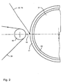
- a ruby laser or a neodymium-YAG laser emits radiant energy high energy density in the form of a first energy beam 12 to the pressure applied to the cylinder 01 printing substance 07, wherein the first energy beam 12 with a normal 13 of a surface 19 of the printing substance 07 an angle ⁇ of more than 0 ° and less than 90 °, preferably less than 45 °.
- At least one second radiation source 14 also with a low beam divergence, z. B.
- a laser 14, in particular a solid-state laser 14 also emits radiant energy high energy density in the form of a second energy beam 16 z. B. to the first cylinder 01 applied on the first printing substance 07, wherein the second energy beam 16 z. B. also with the normal 13 of the surface 19 of the first printing substance 07 or a normal 27 of a surface 19 of a second printing substance 26 forms an angle ⁇ of more than 0 ° and less than 90 °, preferably less than 45 °.
- the arrangement of Radiation sources 11; 14 may be chosen such that the between the normals 13; 27 and the energy beams 12; 16 trained angle ⁇ ; ⁇ are at least approximately equal. Also, the radiation sources 11; 14 be designed such that they z. B.
- a single radiation source which is capable of at least two energy beams 12; 16 to emit, the energy beams 12; 16 have different wavelengths.
- some laser systems can optionally be used to emit energy beams 12; Stimulate 16 different wavelengths.
- its frequency-doubled or frequency-tripled neodymium-YAG laser whose energy beams 12; 16 have half or one third of their natural wavelength of 1064 nm.
- the radiation sources 11; 14 result in that a single radiation source 11, 14, z.
- a dye laser in which preferably organic dyes, eg. As rhodamines, coumarins or oxazines in a carrier medium, for. B.
- a carrier liquid are dissolved, radiation energy in a spectral range of z. B. 60 nm or more, from the at least two energy beams 12; 16 different wavelength preferably by optical devices, eg. B. are separated by filters.
- the radiation sources 11; 14 emit their radiation energy preferably in pulses of short duration, z. B. of significantly less than 1 microseconds, in particular of about 100 ns, but with a high pulse repetition frequency of z. 1 MHz or more.
- the applied on the ink carrier 01 absorption layer 03 absorbs the radiation from the sources 11; 14 emitted radiant energy and converts them into heat or in a momentum transfer, which is explosively formed by thermal expansion or evaporation according to the light hydraulic effect in the printing substance 07, a gas bubble on its exit from the printing substance 07 a portion 18 of the printing substance 07 in the direction of displaced the printing substance 07 spaced substrate 08 and there sets a pressure point.
- a second color carrier 21 which preferably is substantially similar to the above-described first color carrier 01 in construction and in its use, ie, for. B. as a second rotating cylinder 21 z. B. is formed with an absorption layer 22, wherein on the surface of the second cylinder 21, d. H. preferably on the absorption layer 22, with a second cylinder 21 associated with the second inking unit 23 with z. B. at least one inking roller 24, a second printing substance 26 is applied, wherein the first printing substance 07 and the second printing substance 26 preferably differ in their material nature or in their spectral behavior.
- the printing substances used 07; 26 z. B. be formed as two different printing inks, z. B.
- the printing substances 07; 26 is i. d. R. to a dispersion of a solid colorant, a liquid binder and optionally a printing assistant, the printing substance 07; 26 is added to a specific property of the printing substance 07; To achieve 26, such. B. their consistency, drying, abrasion resistance or gloss, wherein the colorant, z. As powdered pigments in the binder, z. B. a viscous, oily varnish is finely distributed.
- a sheet 28 or a web 28, in particular a paper web 28 is disposed at a distance b of preferably less than 2 mm, in particular less than 0.5 mm in front of the second cylinder 21 or at a transport speed v28, preferably a rotational speed v21 of the cylinder 21 is adapted to move in front of the cylinder 21.
- a second guide roller 29 or guide roller 29 may be provided which stabilizes the printing material 28 on the one hand in its position, ie in particular its distance b before the second cylinder 21 and the printing material 28 on the other hand in its transport direction from the cylinder 21 makes distractible, ie the Substrate 28 deflects in particular in a direction away from the cylinder 21 direction.
- the first substrate 08 and the second substrate 28 form a coherent material web 08, 28, the z. B. by means of an arrangement of third pulleys 31 or guide rollers 31 from the first cylinder 01 to the second cylinder 21 is passed.
- the printing machine described so far can be expanded as required by further color carrier and radiation sources, but this is not shown in detail in the figures for the sake of clarity.
- the printing press can be upgraded to a multi-color printing machine, which is able to print the usual four primary colors black, cyan, magenta and yellow as well as optionally further spot colors and special colors substantially simultaneously, these printing substances obviously differing in their material nature and in their spectral behavior.
- the energy beams 12; 16, preferably those of different wavelengths, on the same, z. B. be directed to the first color carrier 01.
- This option allows, on the same color carrier 01 printing substances 07 z. B. the same color, but still different material quality to be printed, the different physical condition z. B. may be due to different formulations of the printing substances 07.
- An alternative arrangement provides that at least one energy beam 12; 16 is directed to another second color carrier 21 or optionally is at least directable. Also, arrangements may be provided in which z. B.
- a first energy beam 12 having a first wavelength on three color carrier 01; 21, preferably directed to the color carrier 01 with bright colors, a first energy beam 12 having a first wavelength, whereas, on the color carrier 21 with the black color in the current printing process, a second energy beam 16 with a second wavelength is directed at almost the same time, the wavelengths of the energy beams 12; 16 preferably differ from each other.
- a color carrier 01 could on a color carrier 01; 21 with the color magenta a frequency-doubled neodymium YAG laser with a lying in the green spectral range wavelength of 532 nm, on a color carrier 01; 21 with the cyan color a ruby laser with a wavelength in the red spectral range of 694 nm and on a color carrier 01; 21 with the chromatic yellow (yellow) a GaN semiconductor laser with a lying in the violet-blue spectral wavelength of 395 nm to 440 nm.
- 16 shows the highest efficiency when an energy beam 12; 16 with a wavelength of a to the printing substance 07; 26 complementary spectral range is used.
- a color carrier 01; 21 with the black color can in principle energy beams 12; 16 of any wavelength can be used, however, is in its fundamental frequency operated neodymium-YAG laser with a lying in the infrared range wavelength of 1064 nm is particularly well.
- a single printing machine it is also possible for a single printing machine to have a plurality of radiation sources 11; 14 of different types or with energy beams 12; Be provided 16 different wavelength, so that with respect to the radiation sources 11; 14 and possibly also their arrangement in the printing press results in a solution in the demand selectively for each color carrier 01; 21 and each printing substance 07; 26 the optimal radiation source 11; 14 and the energy beam 12; 16 with the for printing the printing substance 07; 26 optimal wavelength, pulse duration or amount of radiation energy can be used. So z. B.
- the directed onto the fourth ink carrier 01 energy beam 12 is rectified with the transfer direction of the printing substance 07 to the substrate 08 in an arrangement in which each of the four color carrier 01; 21 is formed in each case as a cylinder, can thus at three color carriers 01; 21, the energy beam 12; 16 may be directed from the outside to the cylinder, whereas the fourth color carrier 01, the associated energy beam 12 is directed from the interior of the cylinder to the printing substance 07.
- the energy beam 12 emitting radiation source 11 z. B. be arranged inside the cylinder or the energy beam 12 is directed by the outside of the cylinder arranged radiation source 11 by optical means in the interior of the cylinder and from there z. B. directed by means of mirror to the printing substance 07.
- the radiation sources 11; 14 are preferably arranged stationary with respect to the printing press.
- the laser systems are with their peripheral aggregates, z. B. with the devices for their power supply or cooling, preferably arranged outside the printing press, but they can also in the interior of a trained as a cylinder color carrier 01; Be arranged 21 and the energy beam 12; 16 of the radiation sources 11; 14 is by optical means in the interior of the cylinder trained color carrier 01; 21 passed to from there to the printing substance 07; 26 to be addressed.
- the of the radiation sources 11; 14 emitted energy beams 12; 16 may be changeable with respect to their beam path, z. B. by optical guidance systems or deflection systems to different locations of the printing press, in particular to different color carriers 01; 21 be conductive.
Landscapes
- Physics & Mathematics (AREA)
- Optics & Photonics (AREA)
- Printing Methods (AREA)
- Ink Jet (AREA)
- Coloring (AREA)
- Character Spaces And Line Spaces In Printers (AREA)
- Mechanical Pencils And Projecting And Retracting Systems Therefor, And Multi-System Writing Instruments (AREA)
- Transmission Devices (AREA)
- Thermal Transfer Or Thermal Recording In General (AREA)
Claims (49)
- Machine à imprimer présentant un premier support d'encre (01), où sur le support d'encre (01) est appliquée une substance d'impression (07), où une transmission au moins d'une partie (18) de la substance d'impression (07) à un matériau à imprimer (08) disposé à distance du support d'encre (07), avec utilisation d'un effet photohydraulique, est effectuée, sachant que de l'énergie de rayonnement, transportée à la substance d'impression (07), excite la transmission de la substance d'impression (07) sur le matériau à imprimer (08), caractérisée en ce que, pour le transport de l'énergie de rayonnement au premier support d'encre (01) sont prévus au moins deux rayons d'énergie (12; 16) de longueurs d'onde différentes, où, parmi les rayons d'énergie (12 ; 16) disponibles, de longueurs d'ondes différentes, on choisit comme rayon d'énergie (12 ; 16) et l'on oriente celui-ci sur la substance d'impression (07), celui dont la longueur d'onde excite la substance d'impression (07) appliquée sur le support d'encre (01), pour effectuer le transfert au matériau à imprimer (08).
- Machine à imprimer selon la revendication 1, caractérisée en ce qu'un deuxième support d'encre (21) est prévu, au moins un rayon d'énergie (12 ; 16) étant orienté sur chaque support d'encre (01 ; 21).
- Machine à imprimer selon la revendication 1 ou 2, caractérisée en ce qu'au moins trois supports d'encre (01 ; 21) sont prévus, où, sur au moins l'un des supports d'encre (01 ; 21), est orienté un rayon d'énergie (12 ; 16) ayant une longueur d'onde différant de la longueur d'onde d'un rayon d'énergie (12 ; 16) orienté sur au moins l'un des autres supports d'encre (01 ; 21).
- Machine à imprimer selon la revendication 2 ou 3, caractérisée en ce que les supports d'encre (01 ; 21) portent des substances d'impression (07 ; 26) différentes.
- Machine à imprimer selon la revendication 1, caractérisée en ce que des substances d'impression (07), ayant une propriété de substance différente, peuvent être imprimées sur le même support d'encre.
- Machine à imprimer selon la revendication 4, caractérisée en ce que sur chaque substance d'impression (07 ; 26), parmi les rayons d'énergie (12 ; 16) disponibles, à longueurs d'onde différentes, on oriente le rayon d'énergie (12 ; 16) dont la longueur d'onde excite la substance d'impression (07 ; 25) appliquée sur le support d'encre (03 ; 21) pour produire le transfert au matériau à imprimer (08 ; 28).
- Machine à imprimer présentant un premier support d'encre (01), où sur le support d'encre (01) est appliquée une substance d'impression (07), où une transmission au moins d'une partie (18) de la substance d'impression (07) à un matériau à imprimer (08) disposé à distance du support d'encre (07), avec utilisation d'un effet photohydraulique, est effectuée, sachant que de l'énergie de rayonnement, transportée à la substance d'impression (07), excite la transmission de la substance d'impression (07) sur le matériau à imprimer (08), où un rayon d'énergie (12 ; 16) transporte l'énergie de rayonnement à la substance d'impression (07), caractérisée en ce qu'un deuxième support d'encre (21) est prévu, où sur le deuxième support d'encre (21) est appliquée une substance d'impression (26), un transfert d'au moins une partie (18) de cette substance d'impression (26) à un matériau à imprimer (28) disposé à distance du deuxième support d'encre (21), en utilisant un effet photohydraulique est effectué, un rayon d'énergie (12 ; 16) transportant de l'énergie de rayonnement à la substance d'impression (26) du deuxième support d'encre (21), et des rayons d'énergie (12 ; 16) de longueurs d'onde différentes sont susceptibles d'être orientés sur le même support d'encre (01 ; 21).
- Machine à imprimer selon la revendication 7, caractérisée en ce que, parmi les rayons d'énergie (12 ; 16) disponibles, à longueurs d'onde différentes, on oriente sélectivement, pour chaque support d'encre (01 ; 21) et chaque substance d'impression (07 ; 25), chaque fois comme rayon d'énergie (12 ; 16) sur chacune des substances d'impression (07 ; 26), celui dont la longueur d'onde excite la substance d'impression (07 ; 26) appliquée sur le support d'encre (01 ; 21) respectif, pour le transfert au matériau à imprimer (08 ; 28).
- Machine à imprimer présentant un premier support d'encre (01), où sur le support d'encre (01) est appliquée une substance d'impression (07), un transfert au moins d'une partie (18) de la substance d'impression (07) à un matériau à imprimer (08) disposé à distance du support d'encre (01) avec utilisation d'un effet photoélectrique étant effectué, où la quantité d'énergie transportée à la substance d'impression (07) excite le transfert de la substance d'impression (07) sur le matériau à imprimer (08), un rayon d'énergie (12 ; 16) transportant l'énergie de rayonnement à la substance à imprimer (07), caractérisée en ce qu'un deuxième support d'encre (21) est prévu, sur le deuxième support d'encre (21) étant appliquée une substance d'impression (26), un transfert, entre au moins une partie (18) de cette substance d'impression (26) à un matériau à imprimer (28), disposé à distance du deuxième support d'encre (21), avec utilisation d'un effet photohydraulique, étant effectué, un rayon d'énergie (12; 16) transportant de l'énergie de rayonnement à la substance d'impression (26) du deuxième support d'encre (21), où, pour au moins l'un des supports (01 ; 21), pour différentes substances d'impression (07 ; 26) sont utilisés de façon sélective des rayons d'énergie (12 ; 16) à guidage du rayon différent, un rayon d'énergie (12 ; 16) orienté sur un support d'encre (01 ; 21) étant orienté à l'identique de la direction de transfert de la substance d'impression (07 ; 26) au matériau à imprimer (08 ; 28), tandis qu'un rayon d'énergie (12 ; 16) orienté sur au moins un autre support d'encre (01 ; 21) touche la surface (19) de la substance d'impression (07 ; 25) sous un angle (α; β) formé avec la normale (13 ; 27) de la surface (19) de la substance d'impression (07 ; 26).
- Machine à imprimer selon la revendication 4 ou 7, caractérisée en ce que les substances d'impression (07 ; 26) des supports d'encre (01 ; 21) se distinguent au niveau de leur propriétés de matière, ou de leur comportement spectral.
- Machine à imprimer selon l'une des revendications 7 à 10, caractérisée en ce qu'au moins trois supports d'encre (01 ; 21) sont prévus, les supports d'encre (01 ; 21) portant des substances d'impression (07 ; 26) différentes.
- Machine à imprimer selon l'une des revendications 7 à 11, caractérisée en ce que de l'énergie de rayonnement, transportée dans le processus d'impression se déroulant, pratiquement simultanément, aux substances d'impression (07 ; 26), excite le transfert de la substance d'impression (07 ; 26) respective des supports d'encre (01 ; 21) au même matériau à imprimer (08 ; 28).
- Machine à imprimer selon l'une des revendications 7, 9 ou 11, caractérisée en ce qu'un rayon d'énergie (12 ; 16) de même longueur d'onde est orienté sur chaque support d'encre (01 ; 21).
- Machine à imprimer selon l'une des revendications précédentes, caractérisée en ce qu'une source de rayonnement (11 ; 14) émet l'énergie de rayonnement.
- Machine à imprimer selon l'une des revendications précédentes, caractérisée en ce qu'une source de rayonnement (11 ; 14) est prévue, émettant son énergie de rayonnement dans une plage spectrale, d'où au moins deux rayons d'énergie (12 ; 16), de longueurs d'ondes différentes, peuvent être séparés.
- Machine à imprimer selon l'une des revendications précédentes, caractérisée en ce qu'au moins deux sources de rayonnement (11 ; 14) sont prévues, émettant les rayons d'énergie (12 ; 16) de longueurs d'ondes différentes.
- Machine à imprimer selon l'une des revendications précédentes, caractérisée en ce qu'est prévue une source de rayonnement (11 ; 14), qui émet au choix les rayons d'énergie (12 ; 16) de longueurs d'onde différentes.
- Machine à imprimer selon l'une des revendications précédentes, caractérisée en ce que la source de rayonnement (11 ; 14) est un laser (11 ;14).
- Machine à imprimer selon l'une des revendications précédentes, caractérisée en ce que les rayons d'énergie (12 ; 16) sont composés d'impulsions d'une durée de moins de 1 µs.
- Machine à imprimer selon l'une des revendications précédentes, caractérisée en ce que les rayons d'énergie (12 ; 16) sont composés d'impulsions ayant une fréquence de répétition d'impulsions d'au moins 1 MHz.
- Machine à imprimer selon l'une des revendications précédentes, caractérisée en ce que le rayon d'énergie (12 ; 16) d'au moins une source de rayonnement (11 ; 14) peut être orientée au choix sur des supports d'encre (01 ; 21) différents.
- Machine à imprimer selon l'une des revendications précédentes, caractérisée en ce que la source de rayonnement (11 ; 14) est disposée de façon également fixe par rapport à la machine à imprimer, un trajet de rayon, du rayon d'énergie (12; 16) émis, étant susceptible d'être guidé, par des systèmes de guidage ou des systèmes de renvoi optiques, sur des emplacements différents de la machine à imprimer.
- Machine à imprimer selon la revendication 22, caractérisée en ce que le rayon d'énergie (12 ; 16) orienté sur le support d'encre (01 ; 21) est guidé à l'identique de la direction de transfert de la substance d'impression (07 ; 26) par rapport au matériau à imprimer (08 ; 28).
- Machine à imprimer selon la revendication 1 ou 7, caractérisée en ce qu'au moins un rayon d'énergie (12 ; 16) touche la surface (19) de la substance d'impression (07 ; 26) sous un angle (α, β) formé avec une normale (13 ; 27) d'une surface (19) de la substance d'impression (07 ; 26).
- Machine à imprimer selon la revendication 9 ou 24, caractérisée en ce que l'angle (α, β) est supérieur à 0° et inférieur à 90°.
- Machine à imprimer selon la revendication 25, caractérisée en ce que l'angle (α, β) est supérieur à 0° et inférieur à 45°.
- Machine à imprimer selon l'une des revendications 25 ou 26, caractérisée en ce que les angles (α, β) de deux rayons d'énergie (12 ; 16) différents sont au moins à peu près de même valeur.
- Machine à imprimer selon l'une des revendications précédentes, caractérisée en ce qu'une couche d'absorption (03 ; 22) est appliquée sur au moins un support d'encre (01 ; 21).
- Machine à imprimer selon la revendication 28, caractérisée en ce que la couche d'absorption (03 ; 22) est appliquée sur toute la surface.
- Machine à imprimer selon l'une des revendications précédentes, caractérisée en ce qu'au moins un support d'encre (01 ; 21) est réalisé sous la forme de cylindre (01 ; 21) rotatif.
- Machine à imprimer selon l'une des revendications précédentes, caractérisée en ce qu'un premier matériau à imprimer (08) est disposé à une distance (a) du premier support d'encre (01) et un deuxième matériau à imprimer (28) est disposé à une distance (b) du deuxième support d'encre (21).
- Machine à imprimer selon la revendication 31, caractérisée en ce que la distance (a) vis-à-vis du premier support d'encre (01) ou la distance (b) vis-à-vis du deuxième d'encre (21) est inférieure à 2 mm.
- Machine à imprimer selon l'une des revendications 31 ou 32, caractérisée en ce que la distance (a) vis-à-vis du premier support d'encre (01) ou la distance (b) vis-à-vis du deuxième support d'encre (21) est inférieure à 0,5 mm.
- Machine à imprimer selon la revendication 31, caractérisée en ce que le matériau à imprimer (08 ; 28) est une bande de matériau (08 ; 28), en particulier une bande de papier (08 ; 28).
- Machine à imprimer selon l'une des revendications 31 ou 34, caractérisée en ce que le premier matériau à imprimer (08) et le deuxième matériau à imprimer (28) forment une bande de matériau cohérente.
- Machine à imprimer selon la revendication 31, caractérisée en ce que le matériau à imprimer (08 ; 28) est réalisé sous forme d'une feuille (08, 28).
- Machine à imprimer selon l'une des revendications 31, 34, 35 ou 36, caractérisée en ce que le matériau à imprimer (08 ; 28) passe devant le support d'encre (01 ; 21) à une vitesse de transport (v08 ; v38).
- Machine à imprimer selon la revendication 37, caractérisée en ce que la vitesse de transport (v08 ; v28) du matériau à imprimer (08 ; 28) est adaptée à une vitesse de rotation (v01 ; v21) du support d'encre (01 ; 21).
- Machine à imprimer selon l'une des revendications précédentes, caractérisée en ce que dans la direction axiale au moins d'un support d'encre (01 ; 21) est prévu un rouleau de renvoi (09 ; 29) ou un cylindre de renvoi (09 ; 29).
- Machine à imprimer selon la revendication 39, caractérisé en ce que le rouleau de renvoi (09; 29) ou le cylindre de renvoi (09; 29) stabilise le matériau à imprimer (08; 28) quant à son espacement (a; b) vis-à-vis du support d'encre (01; 21).
- Machine à imprimer selon l'une des revendications 39 ou 40, caractérisé en ce que le rouleau de renvoi (09 ; 29) ou le cylindre de renvoi (09 ; 29) guide le matériau à imprimer (08 ; 28) dans sa direction de transport, en une direction d'écartement vis-à-vis du support d'encre (01 ; 21).
- Machine à imprimer selon la revendication 4 ou 7, caractérisée en ce que, pour différentes substances d'impression (07 ; 26), sont utilisées sélectivement des sources de rayonnement (11; 14) différentes, ou des agencements différents de sources de rayonnement (11; 14), avec des rayons d'énergie (12 ; 16) à longueurs d'ondes différentes ou à guidage de rayon différent.
- Machine à imprimer selon la revendication 1, 7 ou 9, caractérisée en ce que, un autre rayon d'énergie (12 ; 16) ou un autre guidage de rayon que pour l'encre noire est utilisé pour une encre colorée.
- Machine à imprimer selon la revendication 7, 9 ou 43, caractérisée en ce qu'au moins trois couleurs différentes du noir et une couleur noire sont utilisées.
- Machine à imprimer selon l'une des revendications 2 à 4 ou 7, caractérisée en ce qu'un rayon d'énergie (12) orienté sur l'un des supports d'encre (01) est orienté, à l'identique de la direction de transfert de la substance d'impression (07) au matériau à imprimer (08), tandis qu'un rayon d'énergie (16), orienté sur au moins un autre support d'encre (21), touche la surface (19) de la substance d'impression (26), sous un angle (β) formé avec la normale (27) de la surface (19) de la substance d'impression (26).
- Machine à imprimer selon la revendication 1, 7 ou 9, caractérisée en ce qu'au moins quatre supports d'encre (01 ; 21) sont prévus, chaque fois un rayon d'énergie (12 ; 16) étant orienté sur chacun des supports d'encre (01 ; 21), le rayon d'énergie (12 ; 16), en cas de trois supports d'encre (01 ; 21), touchant la surface (19) de la substance d'impression (26) chaque fois sous le même angle (β).
- Machine à imprimer selon la revendication 46, caractérisée en ce que le rayon d'énergie (12) orienté sur le quatrième support d'encre (01) est orienté à l'identique de la direction de transfert de la substance d'impression (07) au matériau à imprimer (08).
- Machine à imprimer selon la revendication 1, 7 ou 9, caractérisée en ce que le rayon d'énergie (12 ; 16) produit une onde de choc dans la substance d'impression (07 ; 26), sachant que l'onde de choc expulse hors de la substance d'impression (07 ; 26) une partie de cette substance d'impression (07 ; 26).
- Machine à imprimer selon la revendication 44, caractérisée en ce que les trois teintes de couleurs sont le cyan, le magenta et le jaune.
Applications Claiming Priority (3)
| Application Number | Priority Date | Filing Date | Title |
|---|---|---|---|
| DE10257132 | 2002-12-06 | ||
| DE10257132 | 2002-12-06 | ||
| PCT/DE2003/002907 WO2004052648A1 (fr) | 2002-12-06 | 2003-09-03 | Machines a imprimer presentant au moins un support d'encre |
Publications (2)
| Publication Number | Publication Date |
|---|---|
| EP1567344A1 EP1567344A1 (fr) | 2005-08-31 |
| EP1567344B1 true EP1567344B1 (fr) | 2007-04-04 |
Family
ID=32336073
Family Applications (1)
| Application Number | Title | Priority Date | Filing Date |
|---|---|---|---|
| EP03750306A Expired - Lifetime EP1567344B1 (fr) | 2002-12-06 | 2003-09-03 | Machines a imprimer presentant au moins un support d'encre |
Country Status (6)
| Country | Link |
|---|---|
| US (1) | US7415928B2 (fr) |
| EP (1) | EP1567344B1 (fr) |
| AT (1) | ATE358583T1 (fr) |
| AU (1) | AU2003269692A1 (fr) |
| DE (2) | DE50306982D1 (fr) |
| WO (1) | WO2004052648A1 (fr) |
Families Citing this family (2)
| Publication number | Priority date | Publication date | Assignee | Title |
|---|---|---|---|---|
| DE102004022230A1 (de) * | 2004-05-04 | 2005-12-08 | Koenig & Bauer Ag | Druckmaschinen mit einem eine Drucksubstanz tragenden Farbträger |
| DE102005024282B4 (de) * | 2005-05-27 | 2012-11-08 | Koenig & Bauer Aktiengesellschaft | Rollenrotationsdruckmaschine |
Family Cites Families (16)
| Publication number | Priority date | Publication date | Assignee | Title |
|---|---|---|---|---|
| BE478771A (fr) | 1946-09-23 | |||
| US3798365A (en) * | 1969-07-14 | 1974-03-19 | P Johnson | Recording method and apparatus utilizing light energy to move record forming material onto a record medium |
| US3745586A (en) * | 1971-07-01 | 1973-07-10 | Rca Corp | Laser writing |
| DE3702643A1 (de) | 1986-02-10 | 1987-08-13 | Toshiba Kawasaki Kk | Tintenstrahlschreiber sowie schreibkopf und schreibkopfkassette dafuer |
| DE3731835A1 (de) * | 1987-09-22 | 1989-03-30 | Siemens Ag | Laserstrahl-induziertes farbdrucken |
| US6330857B1 (en) | 1995-06-20 | 2001-12-18 | Sergei Nikolaevich Maximovsky | Printing machine using laser ejection of ink from cells |
| RU2082615C1 (ru) | 1995-06-20 | 1997-06-27 | Сергей Николаевич Максимовский | Печатная машина |
| DE19530284C2 (de) | 1995-08-17 | 2000-12-14 | Heidelberger Druckmasch Ag | Verfahren und Vorrichtungen zur Übertragung von Druckfarbe |
| RU2096183C1 (ru) * | 1995-10-27 | 1997-11-20 | Сергей Николаевич Максимовский | Способ струйной печати и струйная печатающая головка для его осуществления |
| DE19746174C1 (de) | 1997-10-18 | 1999-07-08 | Udo Dr Lehmann | Druckverfahren und Einrichtung zu dessen Durchführung |
| AU3044400A (en) * | 1999-01-04 | 2000-07-24 | Heidelberger Druckmaschinen Ag | Method, device and printing mould for conveying free-flowing printing ink onto aprintable substance |
| DE19955383A1 (de) | 1999-10-29 | 2001-05-03 | Orga Kartensysteme Gmbh | Verfahren zum Aufbringen von farbigen Informationen auf einen Gegenstand |
| JP4353452B2 (ja) | 2000-03-30 | 2009-10-28 | オウレンタム イノベーションズ テクノロジエン ゲーエムベーハー | 印刷方法 |
| RU2170674C1 (ru) * | 2000-04-13 | 2001-07-20 | Максимовский Сергей Николаевич | Способ струйной печати и печатающее устройство для его осуществления |
| JP2002086772A (ja) | 2000-09-14 | 2002-03-26 | Think Laboratory Co Ltd | 複数色転写印刷方法 |
| EP1302735B1 (fr) * | 2001-10-10 | 2014-01-01 | Heidelberger Druckmaschinen Aktiengesellschaft | Dispositif et procédé pour délivrer de l'énergie rayonnante sur un support d'impression dans une machine d'impression planographique |
-
2003
- 2003-09-03 US US10/535,656 patent/US7415928B2/en not_active Expired - Fee Related
- 2003-09-03 EP EP03750306A patent/EP1567344B1/fr not_active Expired - Lifetime
- 2003-09-03 DE DE50306982T patent/DE50306982D1/de not_active Expired - Fee Related
- 2003-09-03 DE DE10340492A patent/DE10340492A1/de not_active Withdrawn
- 2003-09-03 AU AU2003269692A patent/AU2003269692A1/en not_active Abandoned
- 2003-09-03 AT AT03750306T patent/ATE358583T1/de not_active IP Right Cessation
- 2003-09-03 WO PCT/DE2003/002907 patent/WO2004052648A1/fr active IP Right Grant
Non-Patent Citations (1)
| Title |
|---|
| None * |
Also Published As
| Publication number | Publication date |
|---|---|
| AU2003269692A1 (en) | 2004-06-30 |
| EP1567344A1 (fr) | 2005-08-31 |
| DE50306982D1 (de) | 2007-05-16 |
| US20060096475A1 (en) | 2006-05-11 |
| US7415928B2 (en) | 2008-08-26 |
| DE10340492A1 (de) | 2004-06-24 |
| WO2004052648A1 (fr) | 2004-06-24 |
| ATE358583T1 (de) | 2007-04-15 |
Similar Documents
| Publication | Publication Date | Title |
|---|---|---|
| EP1485255B1 (fr) | Procede d'impression de qualite et machine d'impression | |
| EP1268211B1 (fr) | Procede d'impression et machine d'impression associee | |
| DE69833974T2 (de) | Vorrichtung zum Härten von Tinten mittels UV-Licht | |
| DE60119576T2 (de) | Tintenstrahldrucker mit drehbarer trommel für strahlungshärtbare tinte | |
| EP1591246B1 (fr) | Dispositif pour délivrer de l'énergie rayonnante sur un support d'impression | |
| EP1428670B1 (fr) | Appareil et procédé d'impression utilisant de l'encre durcissable par rayonnement UV | |
| EP0759582B1 (fr) | Procédé pour le transfert de l'encre et dispositif et machines pour exécuter ce procédé | |
| DE2843064A1 (de) | Verfahren und vorrichtung zur fluessigkeitsstrahl-aufzeichnung | |
| DE3702643A1 (de) | Tintenstrahlschreiber sowie schreibkopf und schreibkopfkassette dafuer | |
| EP0338025B1 (fr) | Emploi d'un dispositif pour impression par transfert à laser | |
| EP0253300A1 (fr) | Imprimante à transfert thermique | |
| EP2379335A1 (fr) | Procédé et machine d'impression pour l'impression d'un substrat | |
| DE69531508T2 (de) | Verfahren zum tintenstrahldrucken und tintenstrahldruckkopf zur durchführung desverfahrens | |
| DE102009021634B4 (de) | Vorrichtung zum farbigen Bedrucken von Personalisierungsdokumenten | |
| EP1567344B1 (fr) | Machines a imprimer presentant au moins un support d'encre | |
| DE102013215638A1 (de) | Vorrichtung zum Bedrucken von Behältern | |
| EP3281800A1 (fr) | Imprimante à jet d'encre comprenant au moins deux têtes d'impression à jet d'encre | |
| DE19835046A1 (de) | Vorrichtung zum Trocknen von Druckfarbe oder Tinte | |
| DE10051850A1 (de) | Druckverfahren und Druckmaschine hierfür | |
| EP1593513B1 (fr) | Dispositif à imprimer avec au moins deux feuilles colorées et porteuses de substance d'impression | |
| DE102011082394A1 (de) | Verfahren zum Behandeln von Tinte auf porösen Substraten unter Anwendung einer Teilaushärtung, und Vorrichtung, die zum Behandeln von Tinte auf porösen Substraten verwendbar ist | |
| DE102015204980B4 (de) | Druckmaschine mit zumindest einem Selektivtrockner | |
| DE102012024393A1 (de) | Verfahren zum indirekten Auftragen von Druckflüssigkeit auf einen Bedruckstoff | |
| EP3718777B1 (fr) | Dispositif de durcissement d'une encre uv sur un matériau à imprimer | |
| DE102015222753A1 (de) | Bearbeitungsvorrichtung für flaches Material und ein Verfahren zum Bearbeiten eines flachen Materials |
Legal Events
| Date | Code | Title | Description |
|---|---|---|---|
| PUAI | Public reference made under article 153(3) epc to a published international application that has entered the european phase |
Free format text: ORIGINAL CODE: 0009012 |
|
| 17P | Request for examination filed |
Effective date: 20041111 |
|
| AK | Designated contracting states |
Kind code of ref document: A1 Designated state(s): AT BE BG CH CY CZ DE DK EE ES FI FR GB GR HU IE IT LI LU MC NL PT RO SE SI SK TR |
|
| AX | Request for extension of the european patent |
Extension state: AL LT LV MK |
|
| DAX | Request for extension of the european patent (deleted) | ||
| GRAP | Despatch of communication of intention to grant a patent |
Free format text: ORIGINAL CODE: EPIDOSNIGR1 |
|
| RIC1 | Information provided on ipc code assigned before grant |
Ipc: B41J 2/005 20060101AFI20061130BHEP Ipc: B41M 5/382 20060101ALI20061130BHEP |
|
| GRAS | Grant fee paid |
Free format text: ORIGINAL CODE: EPIDOSNIGR3 |
|
| GRAA | (expected) grant |
Free format text: ORIGINAL CODE: 0009210 |
|
| AK | Designated contracting states |
Kind code of ref document: B1 Designated state(s): AT BE BG CH CY CZ DE DK EE ES FI FR GB GR HU IE IT LI LU MC NL PT RO SE SI SK TR |
|
| PG25 | Lapsed in a contracting state [announced via postgrant information from national office to epo] |
Ref country code: FI Free format text: LAPSE BECAUSE OF FAILURE TO SUBMIT A TRANSLATION OF THE DESCRIPTION OR TO PAY THE FEE WITHIN THE PRESCRIBED TIME-LIMIT Effective date: 20070404 Ref country code: SI Free format text: LAPSE BECAUSE OF FAILURE TO SUBMIT A TRANSLATION OF THE DESCRIPTION OR TO PAY THE FEE WITHIN THE PRESCRIBED TIME-LIMIT Effective date: 20070404 |
|
| REG | Reference to a national code |
Ref country code: GB Ref legal event code: FG4D Free format text: NOT ENGLISH |
|
| REG | Reference to a national code |
Ref country code: CH Ref legal event code: EP |
|
| GBT | Gb: translation of ep patent filed (gb section 77(6)(a)/1977) |
Effective date: 20070425 |
|
| REF | Corresponds to: |
Ref document number: 50306982 Country of ref document: DE Date of ref document: 20070516 Kind code of ref document: P |
|
| REG | Reference to a national code |
Ref country code: IE Ref legal event code: FG4D Free format text: LANGUAGE OF EP DOCUMENT: GERMAN |
|
| PG25 | Lapsed in a contracting state [announced via postgrant information from national office to epo] |
Ref country code: SE Free format text: LAPSE BECAUSE OF FAILURE TO SUBMIT A TRANSLATION OF THE DESCRIPTION OR TO PAY THE FEE WITHIN THE PRESCRIBED TIME-LIMIT Effective date: 20070704 |
|
| PG25 | Lapsed in a contracting state [announced via postgrant information from national office to epo] |
Ref country code: ES Free format text: LAPSE BECAUSE OF FAILURE TO SUBMIT A TRANSLATION OF THE DESCRIPTION OR TO PAY THE FEE WITHIN THE PRESCRIBED TIME-LIMIT Effective date: 20070715 |
|
| ET | Fr: translation filed | ||
| PG25 | Lapsed in a contracting state [announced via postgrant information from national office to epo] |
Ref country code: PT Free format text: LAPSE BECAUSE OF FAILURE TO SUBMIT A TRANSLATION OF THE DESCRIPTION OR TO PAY THE FEE WITHIN THE PRESCRIBED TIME-LIMIT Effective date: 20070904 |
|
| REG | Reference to a national code |
Ref country code: IE Ref legal event code: FD4D |
|
| PG25 | Lapsed in a contracting state [announced via postgrant information from national office to epo] |
Ref country code: DK Free format text: LAPSE BECAUSE OF FAILURE TO SUBMIT A TRANSLATION OF THE DESCRIPTION OR TO PAY THE FEE WITHIN THE PRESCRIBED TIME-LIMIT Effective date: 20070404 Ref country code: CZ Free format text: LAPSE BECAUSE OF FAILURE TO SUBMIT A TRANSLATION OF THE DESCRIPTION OR TO PAY THE FEE WITHIN THE PRESCRIBED TIME-LIMIT Effective date: 20070404 Ref country code: BG Free format text: LAPSE BECAUSE OF FAILURE TO SUBMIT A TRANSLATION OF THE DESCRIPTION OR TO PAY THE FEE WITHIN THE PRESCRIBED TIME-LIMIT Effective date: 20070704 Ref country code: IE Free format text: LAPSE BECAUSE OF FAILURE TO SUBMIT A TRANSLATION OF THE DESCRIPTION OR TO PAY THE FEE WITHIN THE PRESCRIBED TIME-LIMIT Effective date: 20070404 |
|
| PLBE | No opposition filed within time limit |
Free format text: ORIGINAL CODE: 0009261 |
|
| STAA | Information on the status of an ep patent application or granted ep patent |
Free format text: STATUS: NO OPPOSITION FILED WITHIN TIME LIMIT |
|
| PG25 | Lapsed in a contracting state [announced via postgrant information from national office to epo] |
Ref country code: SK Free format text: LAPSE BECAUSE OF FAILURE TO SUBMIT A TRANSLATION OF THE DESCRIPTION OR TO PAY THE FEE WITHIN THE PRESCRIBED TIME-LIMIT Effective date: 20070404 |
|
| 26N | No opposition filed |
Effective date: 20080107 |
|
| BERE | Be: lapsed |
Owner name: KOENIG & BAUER A.G. Effective date: 20070930 |
|
| PG25 | Lapsed in a contracting state [announced via postgrant information from national office to epo] |
Ref country code: GR Free format text: LAPSE BECAUSE OF FAILURE TO SUBMIT A TRANSLATION OF THE DESCRIPTION OR TO PAY THE FEE WITHIN THE PRESCRIBED TIME-LIMIT Effective date: 20070705 Ref country code: IT Free format text: LAPSE BECAUSE OF FAILURE TO SUBMIT A TRANSLATION OF THE DESCRIPTION OR TO PAY THE FEE WITHIN THE PRESCRIBED TIME-LIMIT Effective date: 20070404 Ref country code: MC Free format text: LAPSE BECAUSE OF NON-PAYMENT OF DUE FEES Effective date: 20070930 |
|
| REG | Reference to a national code |
Ref country code: CH Ref legal event code: PL |
|
| PG25 | Lapsed in a contracting state [announced via postgrant information from national office to epo] |
Ref country code: RO Free format text: LAPSE BECAUSE OF FAILURE TO SUBMIT A TRANSLATION OF THE DESCRIPTION OR TO PAY THE FEE WITHIN THE PRESCRIBED TIME-LIMIT Effective date: 20070404 |
|
| PG25 | Lapsed in a contracting state [announced via postgrant information from national office to epo] |
Ref country code: LI Free format text: LAPSE BECAUSE OF NON-PAYMENT OF DUE FEES Effective date: 20070930 Ref country code: CH Free format text: LAPSE BECAUSE OF NON-PAYMENT OF DUE FEES Effective date: 20070930 |
|
| PG25 | Lapsed in a contracting state [announced via postgrant information from national office to epo] |
Ref country code: BE Free format text: LAPSE BECAUSE OF NON-PAYMENT OF DUE FEES Effective date: 20070930 |
|
| PG25 | Lapsed in a contracting state [announced via postgrant information from national office to epo] |
Ref country code: AT Free format text: LAPSE BECAUSE OF NON-PAYMENT OF DUE FEES Effective date: 20070903 |
|
| PGFP | Annual fee paid to national office [announced via postgrant information from national office to epo] |
Ref country code: NL Payment date: 20080930 Year of fee payment: 6 |
|
| PGFP | Annual fee paid to national office [announced via postgrant information from national office to epo] |
Ref country code: GB Payment date: 20080924 Year of fee payment: 6 |
|
| PG25 | Lapsed in a contracting state [announced via postgrant information from national office to epo] |
Ref country code: EE Free format text: LAPSE BECAUSE OF FAILURE TO SUBMIT A TRANSLATION OF THE DESCRIPTION OR TO PAY THE FEE WITHIN THE PRESCRIBED TIME-LIMIT Effective date: 20070404 |
|
| PGFP | Annual fee paid to national office [announced via postgrant information from national office to epo] |
Ref country code: DE Payment date: 20080929 Year of fee payment: 6 |
|
| PGFP | Annual fee paid to national office [announced via postgrant information from national office to epo] |
Ref country code: FR Payment date: 20080922 Year of fee payment: 6 |
|
| PG25 | Lapsed in a contracting state [announced via postgrant information from national office to epo] |
Ref country code: CY Free format text: LAPSE BECAUSE OF FAILURE TO SUBMIT A TRANSLATION OF THE DESCRIPTION OR TO PAY THE FEE WITHIN THE PRESCRIBED TIME-LIMIT Effective date: 20070404 |
|
| PG25 | Lapsed in a contracting state [announced via postgrant information from national office to epo] |
Ref country code: LU Free format text: LAPSE BECAUSE OF NON-PAYMENT OF DUE FEES Effective date: 20070903 |
|
| PG25 | Lapsed in a contracting state [announced via postgrant information from national office to epo] |
Ref country code: HU Free format text: LAPSE BECAUSE OF FAILURE TO SUBMIT A TRANSLATION OF THE DESCRIPTION OR TO PAY THE FEE WITHIN THE PRESCRIBED TIME-LIMIT Effective date: 20071005 Ref country code: TR Free format text: LAPSE BECAUSE OF FAILURE TO SUBMIT A TRANSLATION OF THE DESCRIPTION OR TO PAY THE FEE WITHIN THE PRESCRIBED TIME-LIMIT Effective date: 20070404 |
|
| REG | Reference to a national code |
Ref country code: NL Ref legal event code: V1 Effective date: 20100401 |
|
| GBPC | Gb: european patent ceased through non-payment of renewal fee |
Effective date: 20090903 |
|
| REG | Reference to a national code |
Ref country code: FR Ref legal event code: ST Effective date: 20100531 |
|
| PG25 | Lapsed in a contracting state [announced via postgrant information from national office to epo] |
Ref country code: FR Free format text: LAPSE BECAUSE OF NON-PAYMENT OF DUE FEES Effective date: 20090930 Ref country code: NL Free format text: LAPSE BECAUSE OF NON-PAYMENT OF DUE FEES Effective date: 20100401 Ref country code: DE Free format text: LAPSE BECAUSE OF NON-PAYMENT OF DUE FEES Effective date: 20100401 |
|
| PG25 | Lapsed in a contracting state [announced via postgrant information from national office to epo] |
Ref country code: GB Free format text: LAPSE BECAUSE OF NON-PAYMENT OF DUE FEES Effective date: 20090903 |