EP1566550A2 - Vorrichtung zur pneumatischen Steuerung - Google Patents
Vorrichtung zur pneumatischen Steuerung Download PDFInfo
- Publication number
- EP1566550A2 EP1566550A2 EP05000446A EP05000446A EP1566550A2 EP 1566550 A2 EP1566550 A2 EP 1566550A2 EP 05000446 A EP05000446 A EP 05000446A EP 05000446 A EP05000446 A EP 05000446A EP 1566550 A2 EP1566550 A2 EP 1566550A2
- Authority
- EP
- European Patent Office
- Prior art keywords
- designed
- base element
- functional module
- quick adjustment
- functional modules
- Prior art date
- Legal status (The legal status is an assumption and is not a legal conclusion. Google has not performed a legal analysis and makes no representation as to the accuracy of the status listed.)
- Granted
Links
Images


Classifications
-
- F—MECHANICAL ENGINEERING; LIGHTING; HEATING; WEAPONS; BLASTING
- F15—FLUID-PRESSURE ACTUATORS; HYDRAULICS OR PNEUMATICS IN GENERAL
- F15B—SYSTEMS ACTING BY MEANS OF FLUIDS IN GENERAL; FLUID-PRESSURE ACTUATORS, e.g. SERVOMOTORS; DETAILS OF FLUID-PRESSURE SYSTEMS, NOT OTHERWISE PROVIDED FOR
- F15B13/00—Details of servomotor systems ; Valves for servomotor systems
- F15B13/02—Fluid distribution or supply devices characterised by their adaptation to the control of servomotors
- F15B13/06—Fluid distribution or supply devices characterised by their adaptation to the control of servomotors for use with two or more servomotors
- F15B13/08—Assemblies of units, each for the control of a single servomotor only
- F15B13/0803—Modular units
- F15B13/0846—Electrical details
- F15B13/086—Sensing means, e.g. pressure sensors
-
- B—PERFORMING OPERATIONS; TRANSPORTING
- B29—WORKING OF PLASTICS; WORKING OF SUBSTANCES IN A PLASTIC STATE IN GENERAL
- B29C—SHAPING OR JOINING OF PLASTICS; SHAPING OF MATERIAL IN A PLASTIC STATE, NOT OTHERWISE PROVIDED FOR; AFTER-TREATMENT OF THE SHAPED PRODUCTS, e.g. REPAIRING
- B29C49/00—Blow-moulding, i.e. blowing a preform or parison to a desired shape within a mould; Apparatus therefor
- B29C49/42—Component parts, details or accessories; Auxiliary operations
-
- F—MECHANICAL ENGINEERING; LIGHTING; HEATING; WEAPONS; BLASTING
- F15—FLUID-PRESSURE ACTUATORS; HYDRAULICS OR PNEUMATICS IN GENERAL
- F15B—SYSTEMS ACTING BY MEANS OF FLUIDS IN GENERAL; FLUID-PRESSURE ACTUATORS, e.g. SERVOMOTORS; DETAILS OF FLUID-PRESSURE SYSTEMS, NOT OTHERWISE PROVIDED FOR
- F15B13/00—Details of servomotor systems ; Valves for servomotor systems
- F15B13/02—Fluid distribution or supply devices characterised by their adaptation to the control of servomotors
- F15B13/06—Fluid distribution or supply devices characterised by their adaptation to the control of servomotors for use with two or more servomotors
- F15B13/08—Assemblies of units, each for the control of a single servomotor only
- F15B13/0803—Modular units
- F15B13/0807—Manifolds
- F15B13/0814—Monoblock manifolds
-
- F—MECHANICAL ENGINEERING; LIGHTING; HEATING; WEAPONS; BLASTING
- F15—FLUID-PRESSURE ACTUATORS; HYDRAULICS OR PNEUMATICS IN GENERAL
- F15B—SYSTEMS ACTING BY MEANS OF FLUIDS IN GENERAL; FLUID-PRESSURE ACTUATORS, e.g. SERVOMOTORS; DETAILS OF FLUID-PRESSURE SYSTEMS, NOT OTHERWISE PROVIDED FOR
- F15B13/00—Details of servomotor systems ; Valves for servomotor systems
- F15B13/02—Fluid distribution or supply devices characterised by their adaptation to the control of servomotors
- F15B13/06—Fluid distribution or supply devices characterised by their adaptation to the control of servomotors for use with two or more servomotors
- F15B13/08—Assemblies of units, each for the control of a single servomotor only
- F15B13/0803—Modular units
- F15B13/0846—Electrical details
- F15B13/0864—Signalling means, e.g. LEDs
-
- F—MECHANICAL ENGINEERING; LIGHTING; HEATING; WEAPONS; BLASTING
- F15—FLUID-PRESSURE ACTUATORS; HYDRAULICS OR PNEUMATICS IN GENERAL
- F15B—SYSTEMS ACTING BY MEANS OF FLUIDS IN GENERAL; FLUID-PRESSURE ACTUATORS, e.g. SERVOMOTORS; DETAILS OF FLUID-PRESSURE SYSTEMS, NOT OTHERWISE PROVIDED FOR
- F15B13/00—Details of servomotor systems ; Valves for servomotor systems
- F15B13/02—Fluid distribution or supply devices characterised by their adaptation to the control of servomotors
- F15B13/06—Fluid distribution or supply devices characterised by their adaptation to the control of servomotors for use with two or more servomotors
- F15B13/08—Assemblies of units, each for the control of a single servomotor only
- F15B13/0803—Modular units
- F15B13/0878—Assembly of modular units
- F15B13/0885—Assembly of modular units using valves combined with other components
- F15B13/0892—Valves combined with fluid components
-
- F—MECHANICAL ENGINEERING; LIGHTING; HEATING; WEAPONS; BLASTING
- F15—FLUID-PRESSURE ACTUATORS; HYDRAULICS OR PNEUMATICS IN GENERAL
- F15B—SYSTEMS ACTING BY MEANS OF FLUIDS IN GENERAL; FLUID-PRESSURE ACTUATORS, e.g. SERVOMOTORS; DETAILS OF FLUID-PRESSURE SYSTEMS, NOT OTHERWISE PROVIDED FOR
- F15B13/00—Details of servomotor systems ; Valves for servomotor systems
- F15B13/02—Fluid distribution or supply devices characterised by their adaptation to the control of servomotors
- F15B13/06—Fluid distribution or supply devices characterised by their adaptation to the control of servomotors for use with two or more servomotors
- F15B13/08—Assemblies of units, each for the control of a single servomotor only
- F15B13/0803—Modular units
- F15B13/0878—Assembly of modular units
- F15B13/0896—Assembly of modular units using different types or sizes of valves
-
- B—PERFORMING OPERATIONS; TRANSPORTING
- B29—WORKING OF PLASTICS; WORKING OF SUBSTANCES IN A PLASTIC STATE IN GENERAL
- B29C—SHAPING OR JOINING OF PLASTICS; SHAPING OF MATERIAL IN A PLASTIC STATE, NOT OTHERWISE PROVIDED FOR; AFTER-TREATMENT OF THE SHAPED PRODUCTS, e.g. REPAIRING
- B29C2949/00—Indexing scheme relating to blow-moulding
- B29C2949/07—Preforms or parisons characterised by their configuration
- B29C2949/0715—Preforms or parisons characterised by their configuration the preform having one end closed
-
- B—PERFORMING OPERATIONS; TRANSPORTING
- B29—WORKING OF PLASTICS; WORKING OF SUBSTANCES IN A PLASTIC STATE IN GENERAL
- B29C—SHAPING OR JOINING OF PLASTICS; SHAPING OF MATERIAL IN A PLASTIC STATE, NOT OTHERWISE PROVIDED FOR; AFTER-TREATMENT OF THE SHAPED PRODUCTS, e.g. REPAIRING
- B29C49/00—Blow-moulding, i.e. blowing a preform or parison to a desired shape within a mould; Apparatus therefor
- B29C49/02—Combined blow-moulding and manufacture of the preform or the parison
- B29C49/06—Injection blow-moulding
-
- B—PERFORMING OPERATIONS; TRANSPORTING
- B29—WORKING OF PLASTICS; WORKING OF SUBSTANCES IN A PLASTIC STATE IN GENERAL
- B29C—SHAPING OR JOINING OF PLASTICS; SHAPING OF MATERIAL IN A PLASTIC STATE, NOT OTHERWISE PROVIDED FOR; AFTER-TREATMENT OF THE SHAPED PRODUCTS, e.g. REPAIRING
- B29C49/00—Blow-moulding, i.e. blowing a preform or parison to a desired shape within a mould; Apparatus therefor
- B29C49/42—Component parts, details or accessories; Auxiliary operations
- B29C49/4289—Valve constructions or configurations, e.g. arranged to reduce blowing fluid consumption
Definitions
- the invention relates to a device for pneumatic A controller comprising a base member having a plurality of pneumatic functional modules.
- Such devices are, for example, as so-called Maintenance units in the production of blow-molded Containers used to carry out one Blowing coordinated feed of one or more To be able to pretend blowing pressures and in order for the realized pneumatic controls and pneumatic functions the required compressed air distributions, pressure indicators and to provide further auxiliary functions.
- preforms made of a thermoplastic material for example preforms made of PET (polyethylene terephthalate), different within a blow molding machine Supplied processing stations.
- PET polyethylene terephthalate
- blower a heater and a Blowing on, in the area of previously tempered preform by biaxial orientation to a container is expanded. The expansion takes place with the help of compressed air, introduced into the preform to be expanded becomes.
- the procedural sequence in such a Expansion of the preform is explained in DE-OS 43 40 291.
- the preforms can as well as the blown containers using different ones Handling facilities are transported. Has proven particularly the use of transport thorns, on which the preforms are attached. The But preforms can also be used with other carrying devices be handled. The use of grippers for handling of preforms and the use of expanding mandrels, the for mounting in an opening region of the preform are also available Constructions.
- blow stations which are arranged on rotating transport wheels, is a book-like Aufklappuza the mold carrier frequently encountered. But it is also possible, relatively movable or to use differently guided mold carriers. For fixed blowing stations, especially for that are suitable for receiving several cavities for container molding, are typically arranged parallel to each other Plates used as a mold carrier.
- the known devices for pneumatic control especially when using larger pressures in the range up to 40 bar and in flowing amounts of compressed air in the order of 20 to 100 m 3 per hour are not yet able to meet all requirements for easy assembly and disassembly to fulfill at the same time high functionality.
- Object of the present invention is therefore an apparatus of the type mentioned in the opening paragraph, that provided an improved ease of installation becomes.
- the Base element designed as a pneumatic distributor is at least one at least two connection points having interconnecting supply channel and that in the area of at least one connection point of at least one the functional modules can be arranged and that the base element and at least one of the functional modules of both Coarse adjustment as well as of an end position fixation with each other are connected.
- the base element By forming the base element as a basic module, connected to the connection points for the function modules is it possible to provide a highly modularized system, in particular, an exchange of functional modules supported with little effort.
- current As maintenance units trained devices for Pneumatic control usually requires it all used function modules to solve each other and after an exchange of the defective functional module together again connect to.
- connection points For the function modules directly at the base element are works exclusively on the relevant functional module required, without the other functional modules thereof be affected.
- functional modules for powerful pneumatic controls.
- Valve units used as functional modules whose weight in the range of 5 to 10 kg.
- function modules designed as filters, the height of about 50 cm and a diameter of about 25 cm.
- the quick adjustment according to the invention makes it possible to the functional module initially in the region of the base element roughly fix and the respective fitter of it too relieve, make a manual mounting of the function module to have to.
- a final assembly and attachment of the functional module on the base element using the End position fixation can then be two-handed and without impairments by a manually to be supported weight of the functional module respectively.
- the holder of a plurality of functional modules is supported by the fact that the supply channel at least partially with an expansion component extends in the direction of a longitudinal axis of the base member.
- connection points arranged one behind the other in the direction of the longitudinal axis are.
- Assembly and disassembly of the functional modules in one Frontal access is supported by the fact that at least two connection points on a front side of the Base element are arranged side by side.
- the modular construction is also supported by that the supply channel at least partially runs within the base element and in im Area of the terminals arranged connections opens.
- a simple production engineering production of the supply channel is supported by the fact that the supply channel formed from at least two holes is, starting from two adjacent connection points run obliquely into the base element.
- the quick adjustment is designed as a latching device.
- Another variant for realizing the quick adjustment is that the quick adjustment as a magnetic device is formed.
- end position fixation is designed as deadlock.
- a further embodiment is that the End position fixation is designed as a tension.
- a typical training of the functional module exists in that the functional module is designed as a switching valve is.
- the functional module is designed as a control valve.
- the functional module is designed as a pressure limiter is.
- the functional module is designed as a vent.
- the functional module is designed as a manometer.
- Another measuring variant is that the functional module is designed as a differential pressure gauge.
- the functional module is designed as a dew point sensor is.
- the base element of at least two in the direction the longitudinal axis of successively arranged element segments is trained.
- a typical application is defined by the fact that the Base element as a mounting base of a maintenance unit is trained.
- the base element is designed as part of a blow molding machine.
- An application with the need to handle a Plurality of heavy function modules is that at least one of the functional modules for the control formed the Blas Kunststoffthese a blowing station is.
- a use of the device for pneumatic control For example, to control the Blas Kunststoffzu arrangement at a device for blow molding.
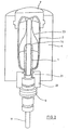
- the principal Construction of a device for forming preforms (1) in container (2) is shown in Fig. 1 and in Fig. 2.
- the device for forming the container (2) consists in Substantially from a blowing station (3), with a blow mold (4) is provided, in which a preform (1) can be used is.
- the preform (1) may be an injection molded part of polyethylene terephthalate.
- To enable a Inserting the preform (1) in the blow mold (4) and the Enabling a removal of the finished container (2) consists of the blow mold (4) of mold halves (5, 6) and a Bottom part (7), which can be positioned by a lifting device (8) is.
- the preform (1) can be in the area of the blowing station (3) to be held by a transport mandrel (9), the together with the preform (1) a plurality of treatment stations goes through inside the device. It is but also possible, for example, the preform (1) Pliers or other handling means directly into the blow mold (4) use.
- a connecting piston (10) arranged which supplies compressed air to the preform (1) and at the same time a seal relative to the transport mandrel (9) makes.
- a connecting piston (10) arranged which supplies compressed air to the preform (1) and at the same time a seal relative to the transport mandrel (9) makes.
- a stretching of the preform (1) takes place with the aid of a Stretching bar (11), positioned by a cylinder (12) becomes.
- a mechanical Positioning of the stretch rod (11) via curve segments to be performed by Abgriffrollen is particularly useful, if a plurality of blowing stations (3) on one rotating blowing wheel are arranged.
- a use of Cylinders (12) is useful when stationarily arranged Blowing stations (3) are provided.
- Fig. 1 is the Stretching system designed such that a tandem arrangement of two cylinders (12) is provided. From a primary cylinder (13), the stretch rod (11) first before beginning the actual stretching process into the area of a Floor (14) of the preform (1) driven. During the actual stretching process, the primary cylinder (13) extended stretch rod together with a primary cylinder (13) carrying carriage (15) from a secondary cylinder (16) or positioned via a cam control. In particular, it is thought to the secondary cylinder (16) to use such a cam-controlled that of a leadership role (17) during the execution of the stretching process slides along a curved path, a current stretching position is given. The guide roller (17) is from the secondary cylinder (16) pressed against the guideway. Of the Carriage (15) slides along two guide elements (18).
- FIG. 2 To adapt to different shapes of a mouth section (21) of the preform (1) is shown in FIG. 2 the Use of separate thread inserts (22) in the area of Blow mold (4) provided.
- Fig. 2 shows in addition to the blown container (2) also Dashed lines drawn the preform (1) and schematically a developing container bladder (23).
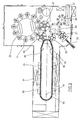
- FIG. 3 shows the basic structure of a blow molding machine, with a heating section (24) and a rotating Blowing wheel (25) is provided.
- a preform input (26) become the preforms (1) of transfer wheels (27, 28, 29) in the area of the heating section (24) transported.
- radiant heaters (30) and blower (31) arranged to the preforms (1) to temper.
- blower (31) After a sufficient temperature the preforms (1) are transferred to the blowing wheel (25), arranged in the region of the blowing stations (3) are.
- the finished blown containers (2) will be replaced by others Transfer wheels a discharge line (32) supplied.
- thermoplastic material can be different Plastics are used. Suitable for example PET, PEN or PP.
- the expansion of the preform (1) during the orientation process done by compressed air supply.
- the Compressed air supply is in a Vorblasphase, in the gas, For example, compressed air supplied at a low pressure level becomes and in a subsequent main blowing phase divided, fed in the gas with a higher pressure level becomes.
- During the pre-blowing phase becomes typical Compressed air at a pressure in the interval from 10 bar to 25 bar and during the main blowing phase is compressed air supplied with a pressure in the interval from 25 bar to 40 bar.
- Fig. 3 From Fig. 3 is also seen that in the illustrated Embodiment, the heating section (24) of a Variety of rotating transport elements (33) formed is strung together in a chain and along by pulleys (34) are guided. In particular, it is thought essentially by the chain-type arrangement réellespannen rectangular base contour. In the illustrated Embodiment will be in the area of the transfer wheel (29) and an input wheel (35) facing extension the heating section (24) a single relatively large-sized Deflection wheel (34) and in the area of adjacent Deflectors two comparatively smaller sized deflection wheels (36) used. In principle, however, are also arbitrary other guides conceivable.
- the modified heating section shown in Fig. 4 (24) may be affected by the larger number of radiant heaters (30) a larger amount of preforms (1) per unit time be tempered.
- the blower (31) direct cooling air in the range of cooling air ducts (39), the associated Radiant heaters (30) each opposite and over Outlet openings emit the cooling air.
- the Ausströmraumen is a flow direction for the Cooling air substantially transverse to a transport direction realized the preforms (1).
- the cooling air channels (39) can be located in the area of the radiant heaters (30) opposite Provide surface reflectors for the heating radiation, likewise it is possible over the delivered Cooling air to realize a cooling of the radiant heater (30).
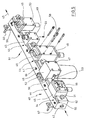
- FIG. 5 shows a trained as a maintenance unit (40) Device for pneumatic control.
- a basic element (41) is with a compressed air supply line (42) as well a compressed gas discharge (43) provided.
- the compressed gas discharge (43) serves a plurality of basic elements (41) in rows.
- the basic element (41) is with a plurality of connection points (44), in whose area functional modules (45) can be arranged.
- the function modules (45) can, for example as switching valves (46), filters (47), control valves (48), pressure limiter (49) or for venting (50) be formed.
- Other forms of realization can as pressure gauge (51), differential pressure gauge (52) or as a dew point sensor (53).
- the functional modules and the base member (41) from a quick adjustment (54) interconnected.
- the quick adjustment (54) from a groove-like depression (55) in the area of the base element (41) and into the depression (55) engaging projections (56) of the larger functional modules (45).
- the recess (55) extends along an upper boundary surface of the base element (41) and the functional modules (45) can with their projections (56) for the realization of the rough assembly in the depression (55).
- a final attachment of the functional modules (45) takes place using an end position fixation (58), in the illustrated embodiment via bolts is realized through the functional modules (45) extend through and into the base member (51) are screwed.
- An attachment of the base element (43) in the region of not shown carrier can be used held by holders (59), for example, under Use screws (60) connected to the carrier become.
- the pressure limiter (49) can be used as a pressure relief valve be formed, one or more has separate outlets (61).
- connection points (44) are preferably in the range a front side (62) of the base element (41).
- For smaller function modules (45) can also Separate connections (63) in the area of the upper boundary surface (57) can be arranged.
- connection points (44) For smaller function modules (45) with relatively low Building weight are between the connection points (44), the for mounting function modules (45) with quick adjustment are provided, further connections arranged. For such a construction can on a comparatively small volume of construction a large number of function modules (45) are mounted.
- connection point (44) connects the Connection point (44) with one in the direction of the compressed air supply adjacent connection point (44) or directly with the compressed gas supply (42).
- the other connection (65) connects the connection point (44) with a in the direction of the compressed gas discharge (43) adjacent Connection point (44) or directly to the compressed gas discharge (43).
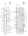
- Fig. 7 illustrates in a horizontal section the Course of the connections (65). It is particularly appropriate that the terminals (65) each relative to a Longitudinal axis (67) of the base element (41) obliquely Have holes (68). The holes (68) of two mutually adjacent connection points (44) each connected at an angle. In the embodiment according to Fig. 7, the angled transitions the holes (68) into each other or the interconnections from bores (68) in the compressed gas feed (42) or the compressed gas discharge (43) in each case in the range of transverse bores (69) arranged starting from the terminals (64) extend into the base member (61).
- connection point (44) are thus two connections (65) associated with each corresponding bore (68).
- Such an arrangement avoids within of the base element (42) in the direction of the longitudinal axis (67) running long contoured connection channels, the only are relatively expensive to manufacture.
- Seals (70) arranged, for example, as Sealing rings may be formed.
- one the two Connections (65) interconnecting transfer element positioned, in terms of its attachment but structurally adapted to the function modules (45) can be designed so that even for these components the same fixing principle as for the Function modules (45) is usable.
- Fig. 8 illustrates in a side view of the arrangement of realized in the region of the base element (41) Part of the quick adjustment (54). As already illustrated in Fig. 5, this is in the region of the base member (41) arranged part of the quick adjustment (54) realized as a groove-like depression (55).
- Fig. 9 illustrates again in a plan view of the Course of the groove-like depression (55) in the region of upper boundary surface (57). Dashed are the inside the base element (41) extending bores (68).
- FIG. 10 illustrates in an enlarged and stronger detailed representation of the function of the quick adjustment (54) as well as the end position fixation (58).
- FIG. 10 illustrates in particular that the depression (55) in the region of their front side (62) facing Extension one starting from the upper boundary surface (57) obliquely downwards and into the depression (55) extending in sliding surface (71).
- the projection (56) with a likewise oblique oriented contact surface (72) due to the gravitational force guided along the sliding surface (71) and the function module (45) is thereby with his Contact surface (73) against the front side (62) of the base element (41) pulled.
Landscapes
- Engineering & Computer Science (AREA)
- Mechanical Engineering (AREA)
- Physics & Mathematics (AREA)
- Fluid Mechanics (AREA)
- General Engineering & Computer Science (AREA)
- Manufacturing & Machinery (AREA)
- Blow-Moulding Or Thermoforming Of Plastics Or The Like (AREA)
- Fluid-Pressure Circuits (AREA)
- Fluid-Driven Valves (AREA)
- Actuator (AREA)
Abstract
Description
- Fig. 1
- Eine perspektivische Darstellung einer Blasstation zur Herstellung von Behältern aus Vorformlingen,
- Fig. 2
- einen Längsschnitt durch eine Blasform, in der ein Vorformling gereckt und expandiert wird,
- Fig. 3
- eine Skizze zur Veranschaulichung eines grundsätzlichen Aufbaus einer Vorrichtung zur Blasformung von Behältern,
- Fig. 4
- eine modifizierte Heizstrecke mit vergrößerter Heizkapazität,
- Fig. 5
- eine perspektivische Darstellung einer als Wartungseinheit ausgebildeten Vorrichtung zur pneumatischen Steuerung,
- Fig. 6
- eine Draufsicht auf ein Basiselement einer Vorrichtung zur pneumatischen Steuerung mit drei Anschlußstellen für Funktionsmodule,
- Fig. 7
- eine teilweise Darstellung eines Horizontalschnittes gemäß Schnittlinie VII-VII in Fig. 6,
- Fig. 8
- eine Seitenansicht gemäß Blickrichtung VIII in Fig. 6,
- Fig. 9
- eine Draufsicht gemäß Blickrichtung IX in Fig. 6 und
- Fig. 10
- eine vergrößerte Querschnittdarstellung zur Veranschaulichung eines Einhängens des Funktionsmoduls mit einem hakenartigen Vorsprung in eine nutartige Vertiefung des Basiselementes, wobei der Vorsprung und die Vertiefung eine Schnellfixierung bereitstellen und wobei von einer verschraubung eine Endlagenfixierung gebildet ist.
Claims (27)
- Vorrichtung zur pneumatischen Steuerung, die ein Basiselement aufweist, das eine Mehrzahl von pneumatischen Funktionsmodulen haltert, dadurch gekennzeichnet, daß das Basiselement (41) als ein pneumatischer Verteiler ausgebildet ist, der mindestens einen mindestens zwei Anschlußstellen (44) miteinander verbindenden Versorgungskanal aufweist und daß im Bereich mindestens einer Anschlußstelle (44) mindestens eines der Funktionsmodule (45) anordbar ist und daß das Basiselement (41) und mindestens eines der Funktionsmodule (45) sowohl von einer Schnelljustierung (45) als auch von einer Endlagenfixierung (58) miteinander verbunden sind.
- Vorrichtung nach Anspruch 1, dadurch gekennzeichnet, daß sich der versorgungskanal mindestens bereichsweise mit einer Ausdehnungskomponente in Richtung einer Längsachse (67) des Basiselementes (41) erstreckt.
- Vorrichtung nach Anspruch 1 oder 2, dadurch gekennzeichnet, daß eine Mehrzahl von Anschlußstellen (44) in Richtung der Längsachse (67) hintereinander angeordnet sind.
- Vorrichtung nach einem der Ansprüche 1 bis 3, dadurch gekennzeichnet, daß mindestens zwei Anschlußstellen (44) auf einer Frontseite (62) des Basiselementes (41) nebeneinander angeordnet sind.
- Vorrichtung nach einem der Ansprüche 1 bis 4, dadurch gekennzeichnet, daß der versorgungskanal mindestens bereichsweise innerhalb des Basiselementes (41) verläuft und in im Bereich der Anschlußstellen (44) angeordnete Anschlüsse (65) einmündet.
- Vorrichtung nach einem der Ansprüche 1 bis 5, dadurch gekennzeichnet, daß der versorgungskanal aus mindestens zwei Bohrungen (68) ausgebildet ist, die ausgehend von zwei benachbarten Anschlußstellen (44) schräg in das Basiselement (41) hinein verlaufen.
- Vorrichtung nach einem der Ansprüche 1 bis 6, dadurch gekennzeichnet, daß die Schnelljustierung (54) als eine Einhängeeinrichtung ausgebildet ist.
- Vorrichtung nach einem der Ansprüche 1 bis 6, dadurch gekennzeichnet, daß die Schnelljustierung (54) als eine Einsteckeinrichtung ausgebildet ist.
- Vorrichtung nach einem der Ansprüche 1 bis 6, dadurch gekennzeichnet, daß die Schnelljustierung (54) als eine Einrastvorrichtung ausgebildet ist.
- Vorrichtung nach einem der Ansprüche 1 bis 6, dadurch gekennzeichnet, daß die Schnelljustierung (54) als eine Magnetvorrichtung ausgebildet ist.
- Vorrichtung nach einem der Ansprüche 1 bis 10, dadurch gekennzeichnet, daß die Endlagenfixierung (58) als Verschraubung ausgebildet ist.
- Vorrichtung nach einem der Ansprüche 1 bis 10, dadurch gekennzeichnet, daß die Endlagenfixierung (58) als Verklemmung ausgebildet ist.
- Vorrichtung nach einem der Ansprüche 1 bis 10, dadurch gekennzeichnet, daß die Endlagenfixierung (58) als Verspannung ausgebildet ist.
- Vorrichtung nach einem der Ansprüche 1 bis 13, dadurch gekennzeichnet, daß das Funktionsmodul (45) als Schaltventil (46) ausgebildet ist.
- Vorrichtung nach einem der Ansprüche 1 bis 13, dadurch gekennzeichnet, daß das Funktionsmodul (45) als Filter (47) ausgebildet ist.
- Vorrichtung nach einem der Ansprüche 1 bis 13, dadurch gekennzeichnet, daß das Funktionsmodul (45) als Regelventil (48) ausgebildet ist.
- Vorrichtung nach einem der Ansprüche 1 bis 13, dadurch gekennzeichnet, daß das Funktionsmodul (45) als Druckbegrenzer (49) ausgebildet ist.
- Vorrichtung nach einem der Ansprüche 1 bis 13, dadurch gekennzeichnet, daß das Funktionsmodul (45) als Entlüftung (50) ausgebildet ist.
- Vorrichtung nach einem der Ansprüche 1 bis 13, dadurch gekennzeichnet, daß das Funktionsmodul (45) als Manometer (51) ausgebildet ist.
- Vorrichtung nach einem der Ansprüche 1 bis 13, dadurch gekennzeichnet, daß das Funktionsmodul (45) als Differenzdruckmanometer (52) ausgebildet ist.
- Vorrichtung nach einem der Ansprüche 1 bis 13, dadurch gekennzeichnet, daß das Funktionsmodul (45) als Taupunktsensor (53) ausgebildet ist.
- Vorrichtung nach einem der Ansprüche 1 bis 21, dadurch gekennzeichnet, daß das Basiselement (41) einteilig ausgebildet ist.
- Vorrichtung nach einem der Ansprüche 1 bis 21, dadurch gekennzeichnet, daß das Basiselement (41) aus mindestens zwei in Richtung der Längsachse (67) hintereinander angeordneten Elementsegmenten ausgebildet ist.
- Vorrichtung nach einem der Ansprüche 1 bis 23, dadurch gekennzeichnet, daß das Basiselement (41) als Montagesockel einer Wartungseinheit ausgebildet ist.
- Vorrichtung nach einem der Ansprüche 1 bis 24, dadurch gekennzeichnet, daß das Basiselement (41) als Teil einer Blasmaschine ausgebildet ist.
- Vorrichtung nach einem der Ansprüche 1 bis 25, dadurch gekennzeichnet, daß mindestens eines der Funktionsmodule (45) zur Steuerung der Blasluftversorgung einer Blasstation (3) ausgebildet ist.
- Vorrichtung nach einem der Ansprüche 1 bis 26, dadurch gekennzeichnet, daß mindestens zwei Basiselemente (41) in Richtung der Längsachse (67) hintereinander angeordnet sind.
Applications Claiming Priority (2)
| Application Number | Priority Date | Filing Date | Title |
|---|---|---|---|
| DE102004008490A DE102004008490A1 (de) | 2004-02-20 | 2004-02-20 | Vorrichtung zur pneumatischen Steuerung |
| DE102004008490 | 2004-02-20 |
Publications (3)
| Publication Number | Publication Date |
|---|---|
| EP1566550A2 true EP1566550A2 (de) | 2005-08-24 |
| EP1566550A3 EP1566550A3 (de) | 2005-10-12 |
| EP1566550B1 EP1566550B1 (de) | 2007-09-26 |
Family
ID=34706878
Family Applications (1)
| Application Number | Title | Priority Date | Filing Date |
|---|---|---|---|
| EP05000446A Expired - Lifetime EP1566550B1 (de) | 2004-02-20 | 2005-01-12 | Vorrichtung zur pneumatischen Steuerung |
Country Status (3)
| Country | Link |
|---|---|
| EP (1) | EP1566550B1 (de) |
| AT (1) | ATE374317T1 (de) |
| DE (2) | DE102004008490A1 (de) |
Cited By (3)
| Publication number | Priority date | Publication date | Assignee | Title |
|---|---|---|---|---|
| WO2008006407A1 (de) * | 2006-07-14 | 2008-01-17 | Eugen Seitz Ag | Vorrichtung zur periodischen resp. zyklischen luftversorgung von maschinen mit hohem druck |
| EP3395538A1 (de) * | 2017-04-27 | 2018-10-31 | Norgren AG | Vorrichtung zur druckluftsteuerung |
| CN110185668A (zh) * | 2019-06-25 | 2019-08-30 | 武汉羽芒智能科技有限公司 | 一种带有安全防护结构的阀岛控制器及其使用方法 |
Families Citing this family (2)
| Publication number | Priority date | Publication date | Assignee | Title |
|---|---|---|---|---|
| DE102019123795A1 (de) | 2019-09-05 | 2021-03-11 | Krones Ag | Vorrichtung und Verfahren zum Umformen von Kunststoffvorformlingen zu Kunststoffbehältnissen mittels stationärer Druckluftzuführung |
| US12170849B2 (en) | 2022-02-04 | 2024-12-17 | Applied Materials, Inc. | Pulsed illumination for fluid inspection |
Citations (3)
| Publication number | Priority date | Publication date | Assignee | Title |
|---|---|---|---|---|
| DE2352926A1 (de) | 1973-10-22 | 1975-04-24 | Heidenreich & Harbeck Gmbh | Verfahren und vorrichtung zum erwaermen eines werkstueckes aus kunststoff |
| DE4212583A1 (de) | 1992-04-15 | 1993-10-21 | Krupp Corpoplast Masch | Vorrichtung zur Blasformung |
| DE4340291A1 (de) | 1993-11-26 | 1995-06-01 | Krupp Corpoplast Masch | Mehrfachnutzung von Blasluft |
Family Cites Families (13)
| Publication number | Priority date | Publication date | Assignee | Title |
|---|---|---|---|---|
| US3465772A (en) * | 1965-11-03 | 1969-09-09 | Ite Imperial Corp | Fluid amplifier system |
| US4188976A (en) * | 1978-02-15 | 1980-02-19 | Austin George K Jr | Multiple dental handpiece control system |
| DE3215782C2 (de) * | 1982-04-28 | 1985-07-11 | Festo-Maschinenfabrik Gottlieb Stoll, 7300 Esslingen | Ventilbank |
| DE69233568T2 (de) * | 1991-09-10 | 2006-08-10 | Smc K.K. | Durch Flüssigkeitsdruck betätigte Vorrichtung |
| DE9410299U1 (de) * | 1994-06-24 | 1994-11-03 | Knocks, Heinz, 59379 Selm | Aus mehreren Modulen bestehendes Druckluftaufbereitungssystem |
| US6293310B1 (en) * | 1996-10-30 | 2001-09-25 | Unit Instruments, Inc. | Gas panel |
| DE19746179C2 (de) * | 1997-10-18 | 1999-08-19 | Festo Ag & Co | Druckluftwartungseinheit |
| DE29810091U1 (de) * | 1998-06-05 | 1998-12-10 | Airtec Pneumatic GmbH, 72829 Engstingen | Ventilterminal mit einer Reihe von Schaltventilen |
| DE19826642C2 (de) * | 1998-06-17 | 2002-01-31 | Lorch Ges & Co Gmbh J | Wartungsvorrichtung für Druckluftanlagen |
| DE19907667C1 (de) * | 1999-02-23 | 2000-09-07 | Daimler Chrysler Ag | Vorrichtung zur Befestigung von pneumatischen und/oder elektropneumatischen Einrichtungen eines Fahrzeugs |
| DE10047469B4 (de) * | 2000-09-21 | 2007-02-01 | Knorr-Bremse Systeme für Nutzfahrzeuge GmbH | Luftaufbereitungsanlage |
| DE10130697A1 (de) * | 2001-03-26 | 2002-10-10 | Ingo Brass | Fluidbetriebenes Steuerungssystem |
| DE10242969B3 (de) * | 2002-09-17 | 2004-04-29 | Festo Ag & Co. | Pneumatische Anordnung mit mehreren Wartungsmodulen zur Druckluftaufbereitung |
-
2004
- 2004-02-20 DE DE102004008490A patent/DE102004008490A1/de not_active Withdrawn
-
2005
- 2005-01-12 DE DE502005001548T patent/DE502005001548D1/de not_active Expired - Fee Related
- 2005-01-12 AT AT05000446T patent/ATE374317T1/de not_active IP Right Cessation
- 2005-01-12 EP EP05000446A patent/EP1566550B1/de not_active Expired - Lifetime
Patent Citations (3)
| Publication number | Priority date | Publication date | Assignee | Title |
|---|---|---|---|---|
| DE2352926A1 (de) | 1973-10-22 | 1975-04-24 | Heidenreich & Harbeck Gmbh | Verfahren und vorrichtung zum erwaermen eines werkstueckes aus kunststoff |
| DE4212583A1 (de) | 1992-04-15 | 1993-10-21 | Krupp Corpoplast Masch | Vorrichtung zur Blasformung |
| DE4340291A1 (de) | 1993-11-26 | 1995-06-01 | Krupp Corpoplast Masch | Mehrfachnutzung von Blasluft |
Cited By (3)
| Publication number | Priority date | Publication date | Assignee | Title |
|---|---|---|---|---|
| WO2008006407A1 (de) * | 2006-07-14 | 2008-01-17 | Eugen Seitz Ag | Vorrichtung zur periodischen resp. zyklischen luftversorgung von maschinen mit hohem druck |
| EP3395538A1 (de) * | 2017-04-27 | 2018-10-31 | Norgren AG | Vorrichtung zur druckluftsteuerung |
| CN110185668A (zh) * | 2019-06-25 | 2019-08-30 | 武汉羽芒智能科技有限公司 | 一种带有安全防护结构的阀岛控制器及其使用方法 |
Also Published As
| Publication number | Publication date |
|---|---|
| EP1566550B1 (de) | 2007-09-26 |
| EP1566550A3 (de) | 2005-10-12 |
| DE102004008490A1 (de) | 2005-09-08 |
| ATE374317T1 (de) | 2007-10-15 |
| DE502005001548D1 (de) | 2007-11-08 |
Similar Documents
| Publication | Publication Date | Title |
|---|---|---|
| DE112006001802B4 (de) | Vorrichtung zur Herstellung von Blasformsegmenten | |
| EP1998950B1 (de) | Verfahren und vorrichtung zur blasformung von behältern unter verwendung von wanddickenmessung des geformten gegenstandes | |
| EP2307185B1 (de) | Verfahren und vorrichtung zur blasformung von behältern | |
| WO2008046369A1 (de) | Verfahren und vorrichtung zur blasformung von behältern | |
| DE112008001904B4 (de) | Vorrichtung zur Blasformung von Behältern | |
| DE102012001229A1 (de) | Verfahren und Vorrichtung zur Blasformung von Behältern | |
| WO2011091780A2 (de) | Verfahren und vorrichtung zur blasformung von behältern | |
| EP2276621B1 (de) | Verfahren und vorrichtung zur blasformung von behältern | |
| DE102007016027A1 (de) | Verfahren und Vorrichtung zur Blasformung von Behältern | |
| EP1868767A2 (de) | Verfahren und vorrichtung zur positionierung eines bauelements | |
| EP1566550B1 (de) | Vorrichtung zur pneumatischen Steuerung | |
| WO2011095151A1 (de) | Verfahren und vorrichtung zur blasformung von behältern | |
| EP1574318B1 (de) | Verfahren und Vorrichtung zur Blasformung von Behältern | |
| EP2544875B1 (de) | Verfahren und vorrichtung zur blasformung von behältern | |
| WO2009089811A1 (de) | Verfahren und vorrichtung zur blasformung von behältern unter verwendung einer höheneinstellbaren transportvorrichtung | |
| EP2681031B1 (de) | Verfahren und vorrichtung zur handhabung von vorformlingen | |
| EP2129508B1 (de) | Verfahren zur blasformung von behältern | |
| DE102005045942A1 (de) | Verfahren und Vorrichtung zur Blasformung von Behältern | |
| DE102006039962B4 (de) | Verfahren und Vorrichtung zur Blasformung von Behältern | |
| DE10355365A1 (de) | Vorrichtung zur Blasformung von Behältern | |
| DE10318556A1 (de) | Verfahren und Vorrichtung zur Blasformung von Behältern | |
| DE102005059057A1 (de) | Verfahren und Vorrichtung zur Blasformung von Behältern | |
| DE102006004940A1 (de) | Verfahren und Vorrichtung zur Blasformung von Behältern |
Legal Events
| Date | Code | Title | Description |
|---|---|---|---|
| PUAI | Public reference made under article 153(3) epc to a published international application that has entered the european phase |
Free format text: ORIGINAL CODE: 0009012 |
|
| AK | Designated contracting states |
Kind code of ref document: A2 Designated state(s): AT BE BG CH CY CZ DE DK EE ES FI FR GB GR HU IE IS IT LI LT LU MC NL PL PT RO SE SI SK TR |
|
| AX | Request for extension of the european patent |
Extension state: AL BA HR LV MK YU |
|
| PUAL | Search report despatched |
Free format text: ORIGINAL CODE: 0009013 |
|
| AK | Designated contracting states |
Kind code of ref document: A3 Designated state(s): AT BE BG CH CY CZ DE DK EE ES FI FR GB GR HU IE IS IT LI LT LU MC NL PL PT RO SE SI SK TR |
|
| AX | Request for extension of the european patent |
Extension state: AL BA HR LV MK YU |
|
| 17P | Request for examination filed |
Effective date: 20051012 |
|
| AKX | Designation fees paid |
Designated state(s): AT BE BG CH CY CZ DE DK EE ES FI FR GB GR HU IE IS IT LI LT LU MC NL PL PT RO SE SI SK TR |
|
| GRAP | Despatch of communication of intention to grant a patent |
Free format text: ORIGINAL CODE: EPIDOSNIGR1 |
|
| GRAS | Grant fee paid |
Free format text: ORIGINAL CODE: EPIDOSNIGR3 |
|
| GRAA | (expected) grant |
Free format text: ORIGINAL CODE: 0009210 |
|
| AK | Designated contracting states |
Kind code of ref document: B1 Designated state(s): AT BE BG CH CY CZ DE DK EE ES FI FR GB GR HU IE IS IT LI LT LU MC NL PL PT RO SE SI SK TR |
|
| REG | Reference to a national code |
Ref country code: GB Ref legal event code: FG4D Free format text: NOT ENGLISH |
|
| REG | Reference to a national code |
Ref country code: CH Ref legal event code: EP |
|
| REF | Corresponds to: |
Ref document number: 502005001548 Country of ref document: DE Date of ref document: 20071108 Kind code of ref document: P |
|
| REG | Reference to a national code |
Ref country code: IE Ref legal event code: FG4D Free format text: LANGUAGE OF EP DOCUMENT: GERMAN |
|
| PG25 | Lapsed in a contracting state [announced via postgrant information from national office to epo] |
Ref country code: LT Free format text: LAPSE BECAUSE OF FAILURE TO SUBMIT A TRANSLATION OF THE DESCRIPTION OR TO PAY THE FEE WITHIN THE PRESCRIBED TIME-LIMIT Effective date: 20070926 Ref country code: FI Free format text: LAPSE BECAUSE OF FAILURE TO SUBMIT A TRANSLATION OF THE DESCRIPTION OR TO PAY THE FEE WITHIN THE PRESCRIBED TIME-LIMIT Effective date: 20070926 |
|
| PG25 | Lapsed in a contracting state [announced via postgrant information from national office to epo] |
Ref country code: PL Free format text: LAPSE BECAUSE OF FAILURE TO SUBMIT A TRANSLATION OF THE DESCRIPTION OR TO PAY THE FEE WITHIN THE PRESCRIBED TIME-LIMIT Effective date: 20070926 |
|
| NLV1 | Nl: lapsed or annulled due to failure to fulfill the requirements of art. 29p and 29m of the patents act | ||
| GBV | Gb: ep patent (uk) treated as always having been void in accordance with gb section 77(7)/1977 [no translation filed] | ||
| PG25 | Lapsed in a contracting state [announced via postgrant information from national office to epo] |
Ref country code: NL Free format text: LAPSE BECAUSE OF FAILURE TO SUBMIT A TRANSLATION OF THE DESCRIPTION OR TO PAY THE FEE WITHIN THE PRESCRIBED TIME-LIMIT Effective date: 20070926 Ref country code: ES Free format text: LAPSE BECAUSE OF FAILURE TO SUBMIT A TRANSLATION OF THE DESCRIPTION OR TO PAY THE FEE WITHIN THE PRESCRIBED TIME-LIMIT Effective date: 20080106 Ref country code: GR Free format text: LAPSE BECAUSE OF FAILURE TO SUBMIT A TRANSLATION OF THE DESCRIPTION OR TO PAY THE FEE WITHIN THE PRESCRIBED TIME-LIMIT Effective date: 20071227 |
|
| REG | Reference to a national code |
Ref country code: IE Ref legal event code: FD4D |
|
| PG25 | Lapsed in a contracting state [announced via postgrant information from national office to epo] |
Ref country code: IS Free format text: LAPSE BECAUSE OF FAILURE TO SUBMIT A TRANSLATION OF THE DESCRIPTION OR TO PAY THE FEE WITHIN THE PRESCRIBED TIME-LIMIT Effective date: 20080126 Ref country code: CZ Free format text: LAPSE BECAUSE OF FAILURE TO SUBMIT A TRANSLATION OF THE DESCRIPTION OR TO PAY THE FEE WITHIN THE PRESCRIBED TIME-LIMIT Effective date: 20070926 Ref country code: PT Free format text: LAPSE BECAUSE OF FAILURE TO SUBMIT A TRANSLATION OF THE DESCRIPTION OR TO PAY THE FEE WITHIN THE PRESCRIBED TIME-LIMIT Effective date: 20080226 Ref country code: SK Free format text: LAPSE BECAUSE OF FAILURE TO SUBMIT A TRANSLATION OF THE DESCRIPTION OR TO PAY THE FEE WITHIN THE PRESCRIBED TIME-LIMIT Effective date: 20070926 |
|
| PG25 | Lapsed in a contracting state [announced via postgrant information from national office to epo] |
Ref country code: RO Free format text: LAPSE BECAUSE OF FAILURE TO SUBMIT A TRANSLATION OF THE DESCRIPTION OR TO PAY THE FEE WITHIN THE PRESCRIBED TIME-LIMIT Effective date: 20070926 Ref country code: SE Free format text: LAPSE BECAUSE OF FAILURE TO SUBMIT A TRANSLATION OF THE DESCRIPTION OR TO PAY THE FEE WITHIN THE PRESCRIBED TIME-LIMIT Effective date: 20071226 |
|
| EN | Fr: translation not filed | ||
| BERE | Be: lapsed |
Owner name: SIG TECHNOLOGY LTD. Effective date: 20080131 |
|
| PG25 | Lapsed in a contracting state [announced via postgrant information from national office to epo] |
Ref country code: DK Free format text: LAPSE BECAUSE OF FAILURE TO SUBMIT A TRANSLATION OF THE DESCRIPTION OR TO PAY THE FEE WITHIN THE PRESCRIBED TIME-LIMIT Effective date: 20070926 |
|
| PLBE | No opposition filed within time limit |
Free format text: ORIGINAL CODE: 0009261 |
|
| STAA | Information on the status of an ep patent application or granted ep patent |
Free format text: STATUS: NO OPPOSITION FILED WITHIN TIME LIMIT |
|
| PG25 | Lapsed in a contracting state [announced via postgrant information from national office to epo] |
Ref country code: MC Free format text: LAPSE BECAUSE OF NON-PAYMENT OF DUE FEES Effective date: 20080131 |
|
| 26N | No opposition filed |
Effective date: 20080627 |
|
| PG25 | Lapsed in a contracting state [announced via postgrant information from national office to epo] |
Ref country code: FR Free format text: LAPSE BECAUSE OF FAILURE TO SUBMIT A TRANSLATION OF THE DESCRIPTION OR TO PAY THE FEE WITHIN THE PRESCRIBED TIME-LIMIT Effective date: 20080704 Ref country code: IE Free format text: LAPSE BECAUSE OF FAILURE TO SUBMIT A TRANSLATION OF THE DESCRIPTION OR TO PAY THE FEE WITHIN THE PRESCRIBED TIME-LIMIT Effective date: 20070926 |
|
| PG25 | Lapsed in a contracting state [announced via postgrant information from national office to epo] |
Ref country code: GB Free format text: LAPSE BECAUSE OF FAILURE TO SUBMIT A TRANSLATION OF THE DESCRIPTION OR TO PAY THE FEE WITHIN THE PRESCRIBED TIME-LIMIT Effective date: 20070926 |
|
| PG25 | Lapsed in a contracting state [announced via postgrant information from national office to epo] |
Ref country code: EE Free format text: LAPSE BECAUSE OF FAILURE TO SUBMIT A TRANSLATION OF THE DESCRIPTION OR TO PAY THE FEE WITHIN THE PRESCRIBED TIME-LIMIT Effective date: 20070926 |
|
| PG25 | Lapsed in a contracting state [announced via postgrant information from national office to epo] |
Ref country code: BE Free format text: LAPSE BECAUSE OF NON-PAYMENT OF DUE FEES Effective date: 20080131 |
|
| PG25 | Lapsed in a contracting state [announced via postgrant information from national office to epo] |
Ref country code: AT Free format text: LAPSE BECAUSE OF NON-PAYMENT OF DUE FEES Effective date: 20080112 |
|
| PGFP | Annual fee paid to national office [announced via postgrant information from national office to epo] |
Ref country code: DE Payment date: 20081020 Year of fee payment: 5 |
|
| PG25 | Lapsed in a contracting state [announced via postgrant information from national office to epo] |
Ref country code: SI Free format text: LAPSE BECAUSE OF FAILURE TO SUBMIT A TRANSLATION OF THE DESCRIPTION OR TO PAY THE FEE WITHIN THE PRESCRIBED TIME-LIMIT Effective date: 20070926 |
|
| PG25 | Lapsed in a contracting state [announced via postgrant information from national office to epo] |
Ref country code: CY Free format text: LAPSE BECAUSE OF FAILURE TO SUBMIT A TRANSLATION OF THE DESCRIPTION OR TO PAY THE FEE WITHIN THE PRESCRIBED TIME-LIMIT Effective date: 20070926 |
|
| PG25 | Lapsed in a contracting state [announced via postgrant information from national office to epo] |
Ref country code: BG Free format text: LAPSE BECAUSE OF FAILURE TO SUBMIT A TRANSLATION OF THE DESCRIPTION OR TO PAY THE FEE WITHIN THE PRESCRIBED TIME-LIMIT Effective date: 20071226 |
|
| REG | Reference to a national code |
Ref country code: CH Ref legal event code: PL |
|
| PG25 | Lapsed in a contracting state [announced via postgrant information from national office to epo] |
Ref country code: LI Free format text: LAPSE BECAUSE OF NON-PAYMENT OF DUE FEES Effective date: 20090131 Ref country code: CH Free format text: LAPSE BECAUSE OF NON-PAYMENT OF DUE FEES Effective date: 20090131 |
|
| PG25 | Lapsed in a contracting state [announced via postgrant information from national office to epo] |
Ref country code: HU Free format text: LAPSE BECAUSE OF FAILURE TO SUBMIT A TRANSLATION OF THE DESCRIPTION OR TO PAY THE FEE WITHIN THE PRESCRIBED TIME-LIMIT Effective date: 20080327 Ref country code: LU Free format text: LAPSE BECAUSE OF NON-PAYMENT OF DUE FEES Effective date: 20080112 |
|
| PG25 | Lapsed in a contracting state [announced via postgrant information from national office to epo] |
Ref country code: TR Free format text: LAPSE BECAUSE OF FAILURE TO SUBMIT A TRANSLATION OF THE DESCRIPTION OR TO PAY THE FEE WITHIN THE PRESCRIBED TIME-LIMIT Effective date: 20070926 |
|
| PG25 | Lapsed in a contracting state [announced via postgrant information from national office to epo] |
Ref country code: DE Free format text: LAPSE BECAUSE OF NON-PAYMENT OF DUE FEES Effective date: 20100803 |
|
| PG25 | Lapsed in a contracting state [announced via postgrant information from national office to epo] |
Ref country code: IT Free format text: LAPSE BECAUSE OF NON-PAYMENT OF DUE FEES Effective date: 20080131 |