EP1566353A2 - Pulverförderpumpe - Google Patents
Pulverförderpumpe Download PDFInfo
- Publication number
- EP1566353A2 EP1566353A2 EP05003280A EP05003280A EP1566353A2 EP 1566353 A2 EP1566353 A2 EP 1566353A2 EP 05003280 A EP05003280 A EP 05003280A EP 05003280 A EP05003280 A EP 05003280A EP 1566353 A2 EP1566353 A2 EP 1566353A2
- Authority
- EP
- European Patent Office
- Prior art keywords
- powder
- delivery chamber
- delivery
- membrane body
- pump according
- Prior art date
- Legal status (The legal status is an assumption and is not a legal conclusion. Google has not performed a legal analysis and makes no representation as to the accuracy of the status listed.)
- Granted
Links
Images


Classifications
-
- B—PERFORMING OPERATIONS; TRANSPORTING
- B05—SPRAYING OR ATOMISING IN GENERAL; APPLYING FLUENT MATERIALS TO SURFACES, IN GENERAL
- B05B—SPRAYING APPARATUS; ATOMISING APPARATUS; NOZZLES
- B05B7/00—Spraying apparatus for discharge of liquids or other fluent materials from two or more sources, e.g. of liquid and air, of powder and gas
- B05B7/14—Spraying apparatus for discharge of liquids or other fluent materials from two or more sources, e.g. of liquid and air, of powder and gas designed for spraying particulate materials
- B05B7/1404—Arrangements for supplying particulate material
- B05B7/1459—Arrangements for supplying particulate material comprising a chamber, inlet and outlet valves upstream and downstream the chamber and means for alternately sucking particulate material into and removing particulate material from the chamber through the valves
-
- B—PERFORMING OPERATIONS; TRANSPORTING
- B65—CONVEYING; PACKING; STORING; HANDLING THIN OR FILAMENTARY MATERIAL
- B65G—TRANSPORT OR STORAGE DEVICES, e.g. CONVEYORS FOR LOADING OR TIPPING, SHOP CONVEYOR SYSTEMS OR PNEUMATIC TUBE CONVEYORS
- B65G53/00—Conveying materials in bulk through troughs, pipes or tubes by floating the materials or by flow of gas, liquid or foam
- B65G53/04—Conveying materials in bulk pneumatically through pipes or tubes; Air slides
- B65G53/28—Systems utilising a combination of gas pressure and suction
-
- B—PERFORMING OPERATIONS; TRANSPORTING
- B65—CONVEYING; PACKING; STORING; HANDLING THIN OR FILAMENTARY MATERIAL
- B65G—TRANSPORT OR STORAGE DEVICES, e.g. CONVEYORS FOR LOADING OR TIPPING, SHOP CONVEYOR SYSTEMS OR PNEUMATIC TUBE CONVEYORS
- B65G53/00—Conveying materials in bulk through troughs, pipes or tubes by floating the materials or by flow of gas, liquid or foam
- B65G53/34—Details
- B65G53/52—Adaptations of pipes or tubes
- B65G53/525—Adaptations of pipes or tubes for conveyance in plug-form
Definitions
- the invention relates to a powder feed pump for use in a powder coating plant.
- PDF powder seal flow promotion
- the actual powder delivery can be done by a Pump pump referred to as a PDF pump, the one Conveying chamber having an inlet and an outlet, wherein sucked through the inlet powder in the delivery chamber and then discharged via the outlet to one Application device (e.g., spray gun or rotary atomizer) to get.
- Application device e.g., spray gun or rotary atomizer
- To fill the delivery chamber is first the outlet of the delivery chamber closed during the Inlet of the delivery chamber is opened to powder out of a To be able to suck in powder containers.
- the delivery chamber can in this case from a hose or pipe section exist, whose hollow cylindrical wall gas-permeable, but is powder-impermeable and thus forms a filter element, wherein the inlet to the delivery chamber through an inlet valve is closable while the outlet from the delivery chamber can be closed by an outlet valve.
- a disadvantage of the known PDF pump described above is the fact that the delivery chamber wall of a porous material that gradually in operation can clog with the powder, reducing the air permeability the winningzelwandung and thus the flow rate decreases.
- the invention is therefore based on the object, in the above-described known PDF pump clogging the air-permeable winningwagdung to prevent.
- the invention comprises the general technical teaching which spellcrowandung in departure from the design principle the above-described known PDF pump essentially To perform gas or airtight and the suction off the delivery chamber for vacuum generation instead in another Way to perform. This will prevent that the powder settle in the delivery chamber wall can. This is especially beneficial because the powder is inside the delivery chamber mainly along the delivery chamber wall flows and therefore settle there particularly easily can.
- the vacuum generation takes place in the delivery chamber in the powder feed pump according to the invention thereby, that the vacuum port in the interior of the delivery chamber to the delivery chamber wall opens spaced apart.
- the powder density close to the wall is particularly large, while the powder density in the middle of the delivery chamber essential is lower, so the risk of clogging with the powder is much lower when to the delivery chamber wall is sucked away at a distance.
- a membrane body arranged at least partially permeable to gas, but is powder-impermeable, the vacuum connection for suction from the delivery chamber in the Membrane body discharges.
- the extraction from the delivery chamber This is done not directly from the delivery chamber, but over the membrane body corresponding to the porous one Wall in the known PDF pump described above forms a filter element.
- the membrane body is preferably to the delivery chamber wall spaced apart and may, for example, within the delivery chamber are located centrally. This is useful because the Powder density within the delivery chamber in the middle essential is lower than in the region of the delivery chamber wall, so that the risk of clogging of the membrane body with the Powder is correspondingly lower.
- the membrane body is preferably streamlined and between the inlet and the outlet of the delivery chamber aligned in the flow direction, wherein the inlet and the outlet of the delivery chamber preferably one another are opposite.
- the membrane body is at least permeable to gas on a large part of its surface, but powder impermeable, resulting in a low flow resistance can reach the membrane body while sucking.
- the membrane body in contrast, on the inlet side facing substantially impermeable to gas and impermeable to powder and on the outlet the delivery chamber facing side gas permeable, but pulverun trim.
- the gas and powder impermeability of Membrane body difficult on the inlet side facing advantageously, the setting of the powder in the Menbran emotions.
- On the outlet side of the Membrane bodies is the risk of setting powder against it Due to the flow significantly lower, so that the membrane body be made gas-permeable on this page can to suck air from the delivery chamber.
- the emptying of the delivery chamber after a previous Filling takes place as in the known described above PDF pump by placing the powder in the delivery chamber is ejected by compressed air.
- the inventive Powder feed pump preferably a positive pressure connection on, within the delivery chamber in the membrane body opens.
- the supply of compressed air for ejection The powder from the delivery chamber takes place here so indirectly via the membrane body, which acts as a filter element.
- the vacuum port for suction from the delivery chamber and the overpressure connection to the Ejecting the powder from the delivery chamber via a common Open the pipe into the membrane body. This is advantageous because so on a separate line for the vacuum connection or the overpressure connection can be dispensed with.
- the overpressure port for ejecting the powder from the delivery chamber directly, d. H. outside the membrane body, in the delivery chamber empties. This is advantageous because of the buildup of pressure in the Delivery chamber when ejecting the powder from the delivery chamber so not hindered by the flow resistance of the membrane body will, what a faster emptying of the delivery chamber allows.
- the invention includes the general technical Doctrine, the negative pressure in the delivery chamber at least partially build up before the inlet of the delivery chamber is opened.
- the inlet into the delivery chamber is thus opened only when already built in the delivery chamber, a negative pressure Has.
- the powder feed pump according to the invention therefore has an inlet valve and a suction valve on, which are independently controllable to before first open the suction valve when opening the inlet valve to be able to create a vacuum in the delivery chamber becomes.
- the generation of the negative pressure in the delivery chamber even ended before the inlet of the delivery chamber is opened.
- the phase of negative pressure generation and the Einsaugphase therefore preferably have no temporal overlap on. This offers the advantage that when aspirating Air from the delivery chamber due to the then closed Inlet no powder can be sucked out, which is undesirable would. For this reason, even on a filter element for Air extraction from the delivery chamber can be dispensed with, thereby With a given amount of equipment a higher negative pressure can generate in the delivery chamber.
- the suction the delivery chamber through a filter element to the suction to prevent residual powder, which may still be in the delivery chamber is located.
- the inlet of the delivery chamber is preferably opened only then if in the delivery chamber a predetermined negative pressure has built up. This offers the advantage of being at the beginning the suction phase defined pressure conditions prevail, so that the suctioned powder amount easily calculate and can be controlled or regulated.
- the exhaust valve closes and at the same time or with a delay time the inlet valve opens when the measured negative pressure reached in the delivery chamber a predetermined limit Has.
- a predetermined negative pressure is constructed by the exhaust valve according to the desired negative pressure for a predetermined period opened becomes, whereby the functional connection between the opening duration of the suction valve and the resulting Negative pressure can be determined by experiments.
- the delivery of the powder located in the delivery chamber through The outlet is preferably carried out by the powder from the Delivery chamber is ejected.
- the powder from the Delivery chamber is ejected.
- For this purpose preferably opens Overpressure connection in the delivery chamber, via which a fluid for discharging the powder introduced into the delivery chamber can be, with the excess pressure port through a discharge valve is closable.
- the discharge valve regardless of the intake valve, the exhaust valve and / or controllable the suction valve. This offers the advantage that the Negative pressure generation phase, the suction phase, the outlet phase and the ejection phase are independently controllable, to achieve optimal promotion behavior.
- a cleaning the delivery chamber by a cleaning fluid is introduced into the delivery chamber.
- a cleaning fluid e.g. Compressed air
- the Cleaning fluid here preferably via the membrane body and not introduced directly into the delivery chamber. This offers the advantage of a slower pressure build-up in the delivery chamber during the cleaning operation, thereby reducing the risk of Bursting of the delivery hose is reduced. It exists, however in the context of the invention alternatively the possibility that the cleaning fluid directly bypassing the membrane body is introduced into the delivery chamber.
- the duration of a complete power stroke is including negative pressure generation phase, suction phase and ejection phase in the range of 200 ms to 1 s, with any Intermediate values are possible and a value of the cycle time of 500 ms is particularly advantageous.
- the vacuum generation phase, the suction phase and the ejection phase can have different lengths or too be the same length, with values between 50 ms and 200 ms or Any intermediate values within this interval possible are.
- This has a duration of 150 ms for the vacuum generation phase, the suction phase and / or the ejection phase proved to be advantageous.
- the invention is not on the values mentioned above for the duration of the Negative pressure generation phase, the suction phase and the ejection phase limited, but in principle with other values realizable.
- Delay times are, for example, in the Range from 20 ms to 200 ms. These delay times should ensure that the respective valves after a suitable control, the desired valve position achieved.
- the invention is in terms of the duration of the delay times does not affect the above limited values, but basically also with other values for the delay time feasible.
- the invention is not limited to one Powder feed pump is limited as a single part, but Rather, a powder coating system with such Powder feed pump includes.
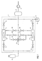
- FIG. 1 shows a powder coating system with a powder feed pump 1 according to the invention for powder supply of a rotary atomizer 2, wherein the Rotary atomizer 2 can be constructed conventionally and therefore, will not be further described below.
- the rotary atomizer 2 can also be another powder application device be used, such as a spray gun.
- the powder feed pump 1 has two parallel switched delivery branches each with a delivery chamber 7, 8 on.
- the two delivery chambers 7, 8 each have an inlet on, wherein the two inlets of the delivery chambers 7, 8 via in each case an inlet valve 9, 10 connected to the powder container 4 are.
- an inlet valve 9, 10 When the inlet valve 9, 10 is open so can the Powder 3 from the powder container 4 in the delivery chambers 7, 8th be sucked in, as will be described in detail.
- the delivery chambers 7, 8 each have an outlet on, wherein the two outlets of the delivery chambers 7, 8 via in each case an outlet valve 11, 12 with the rotary atomizer 2 are connected.
- an outlet valve 11, 12 With the rotary atomizer 2 are connected.
- the intake valves 9, 10 and the exhaust valves 11, 12 can be designed here as pinch valves, the pneumatic, hydraulically or electrically driven.
- a Vacuum generator 13 which is conventional in itself is.
- the vacuum generator 13 has an injector nozzle, which is fed by the compressed air tank 5 with compressed air and according to the venturi principle a negative pressure at a vacuum connection generated.
- the vacuum port of the vacuum generator 13 is over an exhaust valve 14 with a within the delivery chamber. 7 arranged membrane body 15 and connected via a suction valve 16 at a located within the delivery chamber 8 Membrane body 17 connected.
- the membrane body 15, 17 are each gas-permeable, but powder-impermeable, so that over the membrane body 15, 17 air from the delivery chambers 7, 8th can be sucked, whereas the powder 3 in the delivery chambers 7, 8 remains.
- the suction valve 14 is opened is, the vacuum generator 13 sucks over the membrane body 15 air from the delivery chamber 7 and generates there Vacuum for sucking the powder 3 from the powder container 4. Accordingly, the negative pressure generator 13 generates a negative pressure in the delivery chamber 8 when the suction valve 16 is open.
- the compressed air tank 5 is not only with the vacuum generator 13 connected to a negative pressure in the delivery chambers 7, 8, but also serves for ejection of the powder 3 from the delivery chambers 7, 8.
- the Compressed air tank 5 via a discharge valve 18 with the delivery chamber 7 and another discharge valve 19 with the delivery chamber 8 connected.
- the discharge valves 18, 19 is thus compressed air from the compressed air tank. 5 blown into the delivery chambers 7, 8, whereby the in the Delivery chambers 7, 8 located powder 3 from the delivery chambers 7, 8 is ejected, provided that the exhaust valves 11, 12 is opened are.
- the stored in the compressed air tank 5 compressed air is used but not only for ejecting the in the delivery chambers 7, 8 located powder 3, but also for cleaning the delivery chambers 7, 8.
- the compressed air tank 5 via a Cleaning valve 20 with the delivery chamber 7 and in the corresponding Way via a cleaning valve 22 to the delivery chamber 8 connected.
- the compressed air tank 5 thus blows compressed air for cleaning purposes in the delivery chamber 7, if the Cleaning valve 20 is opened. Accordingly becomes Compressed air for cleaning purposes in the delivery chamber. 8 blown when the cleaning valve 22 is open.
- the supply of the cleaning air via the membrane body 15, 17 offers the advantage that the pressure build-up in the cleaning operation slower, which increases the risk of bursting a delivery hose is reduced in the cleaning operation.
- FIG. 2 shows this from above down the temporal opening behavior of the suction valve 14, the intake valve 9, the exhaust valve 11 and the exhaust valve 18.
- the lower four timing diagrams in FIG. 2 show the temporal opening behavior from top to bottom the suction valve 17, the intake valve 10, the exhaust valve 12 and the exhaust valve 19.
- the exhaust valve 14 is opened, while the inlet valve 9, the exhaust valve 11 and the exhaust valve 18 are closed.
- the opening of the suction valve 14 takes place here for a duration T SUCK , which may be in the range of 50 ms and 200 ms.
- T SUCK a duration of a defined negative pressure is generated in the delivery chamber 7, which is later utilized for sucking the powder 3 into the delivery chamber 7, as will be described in detail later.
- the delay time T PAUSE is in the range of 10 ms to 200 ms and ensures that no temporal overlaps of the individual phases of a power stroke occur.
- the inlet valve 9 is then opened so that the negative pressure previously established in the delivery chamber 7 sucks in the powder 3 from the powder container 4, whereby the delivery chamber 7 is filled with powder.
- the inlet valve 9 is in this case opened for a duration T IN , which may be in the range between 50 ms and 200 ms.
- T IN a duration
- the inlet valve 9 is closed, wherein the outlet valve 11, the discharge valve 18 and the suction valve 14 initially remain closed during a further delay time.
- the outlet valve 11 and the discharge valve 18 are then simultaneously opened, so that compressed air is blown from the compressed air tank 5 into the delivery chamber 7, whereby the powder 3 located in the delivery chamber 7 is discharged via the discharge valve 11.
- the opening phase of the exhaust valve 11 may in this case have a duration T OFF , which is in the range of 50 ms to 200 ms.
- the opening phase of the discharge valve 18 may have a duration T PUSH which is in the range of 50 ms to 200 ms.
- the exhaust valve 11 and the exhaust valve 18 are then closed, and the intake valve 9 and the exhaust valve 14 also remain closed for a delay time. After this delay time, the above-described power stroke is cyclically repeated, wherein a clock has a period T PERIODE , which is for example 500 ms.
- the intake valve 10, the exhaust valve 12, the exhaust valve 19 and the exhaust valve 16 are driven in the same manner, but a phase shift T PHASE is provided, which may be in the range of 250 ms.
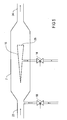
- FIG. 3 shows the delivery chamber 7, wherein the other delivery chamber 8 is constructed analogously and therefore will not be described further.
- the delivery chamber 7 has a Inlet 23, wherein the inlet 23 with the illustrated in Figure 1 Inlet valve 9 is connected.
- the delivery chamber 7 has an outlet 24 which connected to the outlet valve 11 shown in FIG is.
- the membrane body 15 is in this case streamlined and inside the delivery chamber 7 arranged centrally. This is advantageous because the powder density in operation within the delivery chamber 7 near the wall is much larger than in the middle, so that the risk of clogging of the membrane body 15 by the powder 3 in the middle of the delivery chamber 7 least is.
- the membrane body 15 in the delivery chamber. 7 parallel to the flow direction between the inlet 23 and aligned with the outlet 24, so that the membrane body 15 the Flow within the delivery chamber 7 only minimally hindered.
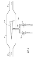
- FIG. 4 shows an alternative embodiment of the delivery chamber 7, which is largely the same as described above and in the embodiment shown in FIG. 3, so that to avoid repetition largely Reference is made to the above description and corresponding Components the same reference numerals as in Figure 3 be used.
- a special feature of this embodiment is that both the compressed air supply to eject the powder. 3 from the delivery chamber 7 and the suction from the delivery chamber 7 for generating negative pressure via the membrane body 15 respectively.
- the exhaust valve 18 and the exhaust valve 14 are in this case via a common line 25 with the membrane body 15 connected. This offers the advantage that within the Delivery chamber 7 can be dispensed with an additional line can.
- a special feature of this embodiment is that the membrane body 15 on the inlet 23 facing Page both gas impermeable and powder impermeable is. In this way it is prevented that the powder 3 by the flow within the delivery chamber 7 in the membrane body 15 can set.
- FIG. 6 combines the shape of the membrane body 15 according to Figure 5 with the common line 25 according to FIG. 4.
Landscapes
- Engineering & Computer Science (AREA)
- Mechanical Engineering (AREA)
- Nozzles (AREA)
- Reciprocating Pumps (AREA)
- Air Transport Of Granular Materials (AREA)
- Jet Pumps And Other Pumps (AREA)
- Control Of The Air-Fuel Ratio Of Carburetors (AREA)
Abstract
Description
- Figur 1
- ein Fluidikdiagramm eines bevorzugten Ausführungsbeispiels einer Pulverbeschichtungsanlage mit einer erfindungsgemäßen Pulverförderpumpe,
- Figur 2
- mehrere Zeitdiagramme zur Verdeutlichung des Öffnungs- und Schließverhaltens der einzelnen Ventile der erfindungsgemäßen Pulverförderpumpe aus Figur 1 sowie
- Figuren 3-6
- verschiedene Ausführungsbeispiele der Förderkammern der Pulverförderpumpe aus Figur 1.
Claims (13)
- Pulverförderpumpe zur Förderung eines Pulvers (3), insbesondere in einer Pulverbeschichtungsanlage, mitdadurch gekennzeichnet, dasseiner Förderkammer (7, 8) mit einer Förderkammerwandung,einem in die Förderkammer (7, 8) mündenden Einlass (23) zur Zuführung des Pulvers (3) in die Förderkammer (7, 8),einem aus der Förderkammer (7, 8) ausmündenden Auslass (24) zur Abgabe des Pulvers (3) aus der Förderkammer (7, 8),einem in die Förderkammer (7, 8) mündenden Unterdruckanschluss zur Erzeugung eines Unterdrucks in der Förderkammer (7, 8) zum Einsaugen des Pulvers (3) in die Förderkammer (7, 8),einem in die Förderkammer (7, 8) mündenden Überdruckanschluss zum Ausblasen des in der Förderkammer (7, 8) befindlichen Pulvers (3) durch den Auslass (24),
die Förderkammerwandung im Wesentlichen gasdicht ist. - Pulverförderpumpe nach Anspruch 1, dadurch gekennzeichnet, dass der Unterdruckanschluss im Inneren der Förderkammer (7, 8) zu der Förderkammerwandung beabstandet ausmündet.
- Pulverförderpumpe nach einem der vorhergehenden Ansprüche, dadurch gekennzeichnet, dass in der Förderkammer (7, 8) ein Membrankörper (15, 17) angeordnet ist, der mindestens teilweise gasdurchlässig, aber pulverundurchlässig ist, wobei der Unterdruckanschluss innerhalb der Förderkammer (7, 8) in dem Membrankörper (15, 17) ausmündet.
- Pulverförderpumpe nach Anspruch 3, dadurch gekennzeichnet, dass der Membrankörper (15, 17) zu der Förderkammerwandung beabstandet angeordnet ist.
- Pulverförderpumpe nach Anspruch 4, dadurch gekennzeichnet, dass der Membrankörper (15, 17) in der Förderkammer (7, 8) im Wesentlichen mittig angeordnet ist.
- Pulverförderpumpe nach einem der Ansprüche 3 bis 5, dadurch gekennzeichnet, dass der Membrankörper (15, 17) stromlinienförmig ist.
- Pulverförderpumpe nach einem der Ansprüche 3 bis 6, dadurch gekennzeichnet, dass der Membrankörper (15, 17) auf einem Großteil seiner Oberfläche gasdurchlässig ist.
- Pulverförderpumpe nach einem der Ansprüche 3 bis 7, dadurch gekennzeichnet, dass der Membrankörper (15, 17) auf der dem Einlass (23) zugewandten Seite gasundurchlässig und pulverundurchlässig und auf dem Auslass (24) zugewandten Seite gasdurchlässig, aber pulverundurchlässig ist.
- Pulverförderpumpe nach einem der Ansprüche 3 bis 8, dadurch gekennzeichnet, dass der Überdruckanschluss innerhalb der Förderkammer (7, 8) in dem Membrankörper (15, 17) ausmündet.
- Pulverförderpumpe nach Anspruch 9, dadurch gekennzeichnet, dass der Unterdruckanschluss und der Überdruckanschluss über eine gemeinsame Leitung (25) in den Membrankörper (15, 17) münden.
- Pulverförderpumpe nach einem der Ansprüche 1 bis 8, dadurch gekennzeichnet, dass der Überdruckanschluss außerhalb des Membrankörpers (15, 17) in die Förderkammer (7, 8) mündet.
- Pulverförderpumpe nach einem der vorhergehenden Ansprüche, dadurch gekennzeichnet, dass der Einlass (23) und der Auslass (24) auf gegenüberliegenden Seiten in die Förderkammer (7, 8) münden.
- Pulverbeschichtungseinrichtung mit einer Pulverförderpumpe nach einem der vorhergehenden Ansprüche.
Applications Claiming Priority (2)
| Application Number | Priority Date | Filing Date | Title |
|---|---|---|---|
| DE102004008495A DE102004008495A1 (de) | 2004-02-20 | 2004-02-20 | Pulverförderpumpe |
| DE102004008495 | 2004-02-20 |
Publications (3)
| Publication Number | Publication Date |
|---|---|
| EP1566353A2 true EP1566353A2 (de) | 2005-08-24 |
| EP1566353A3 EP1566353A3 (de) | 2006-07-12 |
| EP1566353B1 EP1566353B1 (de) | 2007-04-18 |
Family
ID=34706879
Family Applications (1)
| Application Number | Title | Priority Date | Filing Date |
|---|---|---|---|
| EP05003280A Expired - Lifetime EP1566353B1 (de) | 2004-02-20 | 2005-02-16 | Pulverförderpumpe |
Country Status (4)
| Country | Link |
|---|---|
| EP (1) | EP1566353B1 (de) |
| AT (1) | ATE359978T1 (de) |
| DE (2) | DE102004008495A1 (de) |
| ES (1) | ES2284097T3 (de) |
Cited By (3)
| Publication number | Priority date | Publication date | Assignee | Title |
|---|---|---|---|---|
| WO2009044242A1 (en) * | 2007-09-29 | 2009-04-09 | Itw Gema Gmbh | Powder spray coating device and powder transport device therefor |
| ITMI20112166A1 (it) * | 2011-11-28 | 2013-05-29 | Otto Rusterholz | Procedimento e dispositivo tubolare per l' alimentazione controllata di materiali solidi incoerenti nei sistemi a pressione differenziata, particolarmente per trasporti pneumatici |
| EP2311573A3 (de) * | 2005-10-07 | 2014-08-20 | Nordson Corporation | Steuereinrichtung für eine Pumpe für trockenes partikelförmiges Material |
Families Citing this family (2)
| Publication number | Priority date | Publication date | Assignee | Title |
|---|---|---|---|---|
| DE102007045330A1 (de) | 2007-09-22 | 2009-04-02 | Itw Gema Gmbh | Beschichtungspulver-Förderverfahren, Beschichtungspulver-Fördervorrichtung und elektrostatische Pulversprühbeschichtungsvorrichtung |
| DE102013211550A1 (de) * | 2013-06-19 | 2014-12-24 | Gema Switzerland Gmbh | Pulverfördervorrichtung insbesondere für Beschichtungspulver |
Family Cites Families (1)
| Publication number | Priority date | Publication date | Assignee | Title |
|---|---|---|---|---|
| CH676112A5 (de) * | 1988-05-16 | 1990-12-14 | Jean Michel Paux |
-
2004
- 2004-02-20 DE DE102004008495A patent/DE102004008495A1/de not_active Withdrawn
-
2005
- 2005-02-16 EP EP05003280A patent/EP1566353B1/de not_active Expired - Lifetime
- 2005-02-16 ES ES05003280T patent/ES2284097T3/es not_active Expired - Lifetime
- 2005-02-16 DE DE502005000593T patent/DE502005000593D1/de not_active Expired - Lifetime
- 2005-02-16 AT AT05003280T patent/ATE359978T1/de not_active IP Right Cessation
Cited By (6)
| Publication number | Priority date | Publication date | Assignee | Title |
|---|---|---|---|---|
| EP2311573A3 (de) * | 2005-10-07 | 2014-08-20 | Nordson Corporation | Steuereinrichtung für eine Pumpe für trockenes partikelförmiges Material |
| WO2009044242A1 (en) * | 2007-09-29 | 2009-04-09 | Itw Gema Gmbh | Powder spray coating device and powder transport device therefor |
| US8430640B2 (en) | 2007-09-29 | 2013-04-30 | Felix Mauchle | Powder spray coating device and powder transport device therefor |
| ITMI20112166A1 (it) * | 2011-11-28 | 2013-05-29 | Otto Rusterholz | Procedimento e dispositivo tubolare per l' alimentazione controllata di materiali solidi incoerenti nei sistemi a pressione differenziata, particolarmente per trasporti pneumatici |
| WO2013079338A1 (en) * | 2011-11-28 | 2013-06-06 | Otto Rusterholz | Process and tubular device for the controlled feeding of incoherent solid materials in differentiated pressure systems |
| US9617086B2 (en) | 2011-11-28 | 2017-04-11 | Armin Rusterholz | Process and tubular device for the controlled feeding of incoherent solid materials in differentiated pressure systems |
Also Published As
| Publication number | Publication date |
|---|---|
| DE502005000593D1 (de) | 2007-05-31 |
| EP1566353B1 (de) | 2007-04-18 |
| ES2284097T3 (es) | 2007-11-01 |
| DE102004008495A1 (de) | 2005-09-08 |
| ATE359978T1 (de) | 2007-05-15 |
| EP1566353A3 (de) | 2006-07-12 |
Similar Documents
| Publication | Publication Date | Title |
|---|---|---|
| EP1566352B1 (de) | Pulverförderpumpe und zugehöriges Betriebsverfahren | |
| EP2981365B1 (de) | Pulverdichtstrompumpe und entsprechendes betriebsverfahren | |
| EP4366886B1 (de) | Pulverförderkammer für eine pulverdichtstrompumpe sowie pulverdichtstrompumpe mit einer pulverförderkammer | |
| DE1625197A1 (de) | Verteiler | |
| EP1958899B1 (de) | Vorrichtung zum Fördern von Fluid | |
| EP3010645B1 (de) | Pulverfördervorrichtung für beschichtungspulver | |
| DE10145448A1 (de) | Vorrichtung zum Fördern von Pulver und Verfahren zu deren Betrieb | |
| DE2802265A1 (de) | Verfahren und vorrichtung zum entlueften von pulver, beispielsweise milchpulver, das in ein behaeltnis, beispielsweise einen beutel eingefuellt wird | |
| EP3585522B1 (de) | Pulverdichtstrompumpe | |
| DE10353968A1 (de) | Beschichtungspulver-Fördervorrichtung und -Förderverfahren | |
| DE2457316A1 (de) | Verfahren zur herstellung von ejektor-vorrichtungen | |
| EP3455032B1 (de) | Vorrichtung zur herstellung von co2-pellets aus co2-schnee und reinigungsgerät | |
| DE102013205895A1 (de) | Pulverdichtstrompumpe zum Fördern von Beschichtungspulver sowie entsprechendes Verfahren | |
| DE102007045330A1 (de) | Beschichtungspulver-Förderverfahren, Beschichtungspulver-Fördervorrichtung und elektrostatische Pulversprühbeschichtungsvorrichtung | |
| EP3394576A1 (de) | Kleinstmengen-dosiervorrichtung, insbesondere für pharmazeutische anwendungen sowie kleinstmengen-pulverdosierverfahren | |
| EP1427657B1 (de) | Vorrichtung und verfahren zum überführen eines staub-, pulver-, korn- oder granulatartigen fördergutes aus einem lagerbehälter in einen arbeits- oder überführungsbehälter od.dgl. aufnahmeraum | |
| DE102005060833A1 (de) | Pulversprühbeschichtungsvorrichtung und Pulverversorgungsvorrichtung hierfür | |
| EP1566353B1 (de) | Pulverförderpumpe | |
| EP1752399B1 (de) | Vorrichtung und Methode zum Fördern von Pulver | |
| DE19613967A1 (de) | Vorrichtung zur Sprühbeschichtung | |
| DE102007048520A1 (de) | Sprühbeschichtungspulver-Fördervorrichtung und Pulversprühbeschichtungsvorrichtung | |
| DE3410409A1 (de) | Sandungsvorrichtung fuer schienenfahrzeuge | |
| DE2127651B2 (de) | Zerstäubervorrichtung | |
| DE1454825B2 (de) | Verfahren und vorrichtung zum fuellen einer gasdichten form mit kunststoffgranulat | |
| DE102006032184B4 (de) | Vorrichtung zum Fördern pulverförmiger fluidisierter Medien |
Legal Events
| Date | Code | Title | Description |
|---|---|---|---|
| PUAI | Public reference made under article 153(3) epc to a published international application that has entered the european phase |
Free format text: ORIGINAL CODE: 0009012 |
|
| AK | Designated contracting states |
Kind code of ref document: A2 Designated state(s): AT BE BG CH CY CZ DE DK EE ES FI FR GB GR HU IE IS IT LI LT LU MC NL PL PT RO SE SI SK TR |
|
| AX | Request for extension of the european patent |
Extension state: AL BA HR LV MK YU |
|
| PUAL | Search report despatched |
Free format text: ORIGINAL CODE: 0009013 |
|
| AK | Designated contracting states |
Kind code of ref document: A3 Designated state(s): AT BE BG CH CY CZ DE DK EE ES FI FR GB GR HU IE IS IT LI LT LU MC NL PL PT RO SE SI SK TR |
|
| AX | Request for extension of the european patent |
Extension state: AL BA HR LV MK YU |
|
| 17P | Request for examination filed |
Effective date: 20060811 |
|
| GRAP | Despatch of communication of intention to grant a patent |
Free format text: ORIGINAL CODE: EPIDOSNIGR1 |
|
| GRAS | Grant fee paid |
Free format text: ORIGINAL CODE: EPIDOSNIGR3 |
|
| GRAA | (expected) grant |
Free format text: ORIGINAL CODE: 0009210 |
|
| AKX | Designation fees paid |
Designated state(s): AT BE BG CH CY CZ DE DK EE ES FI FR GB GR HU IE IS IT LI LT LU MC NL PL PT RO SE SI SK TR |
|
| AK | Designated contracting states |
Kind code of ref document: B1 Designated state(s): AT BE BG CH CY CZ DE DK EE ES FI FR GB GR HU IE IS IT LI LT LU MC NL PL PT RO SE SI SK TR |
|
| PG25 | Lapsed in a contracting state [announced via postgrant information from national office to epo] |
Ref country code: FI Free format text: LAPSE BECAUSE OF FAILURE TO SUBMIT A TRANSLATION OF THE DESCRIPTION OR TO PAY THE FEE WITHIN THE PRESCRIBED TIME-LIMIT Effective date: 20070418 Ref country code: SI Free format text: LAPSE BECAUSE OF FAILURE TO SUBMIT A TRANSLATION OF THE DESCRIPTION OR TO PAY THE FEE WITHIN THE PRESCRIBED TIME-LIMIT Effective date: 20070418 |
|
| REG | Reference to a national code |
Ref country code: CH Ref legal event code: EP |
|
| REG | Reference to a national code |
Ref country code: IE Ref legal event code: FG4D Free format text: LANGUAGE OF EP DOCUMENT: GERMAN |
|
| REF | Corresponds to: |
Ref document number: 502005000593 Country of ref document: DE Date of ref document: 20070531 Kind code of ref document: P |
|
| REG | Reference to a national code |
Ref country code: DE Ref legal event code: R096 Ref document number: 502005000593 Country of ref document: DE Effective date: 20070531 |
|
| GBT | Gb: translation of ep patent filed (gb section 77(6)(a)/1977) |
Effective date: 20070711 |
|
| REG | Reference to a national code |
Ref country code: SE Ref legal event code: TRGR |
|
| PG25 | Lapsed in a contracting state [announced via postgrant information from national office to epo] |
Ref country code: IS Free format text: LAPSE BECAUSE OF FAILURE TO SUBMIT A TRANSLATION OF THE DESCRIPTION OR TO PAY THE FEE WITHIN THE PRESCRIBED TIME-LIMIT Effective date: 20070818 |
|
| PG25 | Lapsed in a contracting state [announced via postgrant information from national office to epo] |
Ref country code: PT Free format text: LAPSE BECAUSE OF FAILURE TO SUBMIT A TRANSLATION OF THE DESCRIPTION OR TO PAY THE FEE WITHIN THE PRESCRIBED TIME-LIMIT Effective date: 20070918 |
|
| REG | Reference to a national code |
Ref country code: ES Ref legal event code: FG2A Ref document number: 2284097 Country of ref document: ES Kind code of ref document: T3 |
|
| PG25 | Lapsed in a contracting state [announced via postgrant information from national office to epo] |
Ref country code: PL Free format text: LAPSE BECAUSE OF FAILURE TO SUBMIT A TRANSLATION OF THE DESCRIPTION OR TO PAY THE FEE WITHIN THE PRESCRIBED TIME-LIMIT Effective date: 20070418 |
|
| REG | Reference to a national code |
Ref country code: IE Ref legal event code: FD4D |
|
| PG25 | Lapsed in a contracting state [announced via postgrant information from national office to epo] |
Ref country code: CZ Free format text: LAPSE BECAUSE OF FAILURE TO SUBMIT A TRANSLATION OF THE DESCRIPTION OR TO PAY THE FEE WITHIN THE PRESCRIBED TIME-LIMIT Effective date: 20070418 Ref country code: BG Free format text: LAPSE BECAUSE OF FAILURE TO SUBMIT A TRANSLATION OF THE DESCRIPTION OR TO PAY THE FEE WITHIN THE PRESCRIBED TIME-LIMIT Effective date: 20070718 Ref country code: IE Free format text: LAPSE BECAUSE OF FAILURE TO SUBMIT A TRANSLATION OF THE DESCRIPTION OR TO PAY THE FEE WITHIN THE PRESCRIBED TIME-LIMIT Effective date: 20070418 Ref country code: DK Free format text: LAPSE BECAUSE OF FAILURE TO SUBMIT A TRANSLATION OF THE DESCRIPTION OR TO PAY THE FEE WITHIN THE PRESCRIBED TIME-LIMIT Effective date: 20070418 |
|
| PLBE | No opposition filed within time limit |
Free format text: ORIGINAL CODE: 0009261 |
|
| STAA | Information on the status of an ep patent application or granted ep patent |
Free format text: STATUS: NO OPPOSITION FILED WITHIN TIME LIMIT |
|
| PG25 | Lapsed in a contracting state [announced via postgrant information from national office to epo] |
Ref country code: SK Free format text: LAPSE BECAUSE OF FAILURE TO SUBMIT A TRANSLATION OF THE DESCRIPTION OR TO PAY THE FEE WITHIN THE PRESCRIBED TIME-LIMIT Effective date: 20070418 Ref country code: LT Free format text: LAPSE BECAUSE OF FAILURE TO SUBMIT A TRANSLATION OF THE DESCRIPTION OR TO PAY THE FEE WITHIN THE PRESCRIBED TIME-LIMIT Effective date: 20070418 |
|
| 26N | No opposition filed |
Effective date: 20080121 |
|
| PG25 | Lapsed in a contracting state [announced via postgrant information from national office to epo] |
Ref country code: GR Free format text: LAPSE BECAUSE OF FAILURE TO SUBMIT A TRANSLATION OF THE DESCRIPTION OR TO PAY THE FEE WITHIN THE PRESCRIBED TIME-LIMIT Effective date: 20070719 |
|
| REG | Reference to a national code |
Ref country code: DE Ref legal event code: R097 Ref document number: 502005000593 Country of ref document: DE Effective date: 20080121 |
|
| PG25 | Lapsed in a contracting state [announced via postgrant information from national office to epo] |
Ref country code: RO Free format text: LAPSE BECAUSE OF FAILURE TO SUBMIT A TRANSLATION OF THE DESCRIPTION OR TO PAY THE FEE WITHIN THE PRESCRIBED TIME-LIMIT Effective date: 20070418 |
|
| PG25 | Lapsed in a contracting state [announced via postgrant information from national office to epo] |
Ref country code: MC Free format text: LAPSE BECAUSE OF NON-PAYMENT OF DUE FEES Effective date: 20080228 |
|
| PG25 | Lapsed in a contracting state [announced via postgrant information from national office to epo] |
Ref country code: EE Free format text: LAPSE BECAUSE OF FAILURE TO SUBMIT A TRANSLATION OF THE DESCRIPTION OR TO PAY THE FEE WITHIN THE PRESCRIBED TIME-LIMIT Effective date: 20070418 |
|
| PG25 | Lapsed in a contracting state [announced via postgrant information from national office to epo] |
Ref country code: AT Free format text: LAPSE BECAUSE OF NON-PAYMENT OF DUE FEES Effective date: 20080216 |
|
| PG25 | Lapsed in a contracting state [announced via postgrant information from national office to epo] |
Ref country code: CY Free format text: LAPSE BECAUSE OF FAILURE TO SUBMIT A TRANSLATION OF THE DESCRIPTION OR TO PAY THE FEE WITHIN THE PRESCRIBED TIME-LIMIT Effective date: 20070418 |
|
| REG | Reference to a national code |
Ref country code: CH Ref legal event code: PL |
|
| PG25 | Lapsed in a contracting state [announced via postgrant information from national office to epo] |
Ref country code: LI Free format text: LAPSE BECAUSE OF NON-PAYMENT OF DUE FEES Effective date: 20090228 Ref country code: CH Free format text: LAPSE BECAUSE OF NON-PAYMENT OF DUE FEES Effective date: 20090228 |
|
| REG | Reference to a national code |
Ref country code: DE Ref legal event code: R081 Ref document number: 502005000593 Country of ref document: DE Owner name: DUERR SYSTEMS AG, DE Free format text: FORMER OWNER: DUERR SYSTEMS GMBH, 70435 STUTTGART, DE Effective date: 20100115 |
|
| PG25 | Lapsed in a contracting state [announced via postgrant information from national office to epo] |
Ref country code: HU Free format text: LAPSE BECAUSE OF FAILURE TO SUBMIT A TRANSLATION OF THE DESCRIPTION OR TO PAY THE FEE WITHIN THE PRESCRIBED TIME-LIMIT Effective date: 20071019 Ref country code: LU Free format text: LAPSE BECAUSE OF NON-PAYMENT OF DUE FEES Effective date: 20080216 |
|
| PG25 | Lapsed in a contracting state [announced via postgrant information from national office to epo] |
Ref country code: TR Free format text: LAPSE BECAUSE OF FAILURE TO SUBMIT A TRANSLATION OF THE DESCRIPTION OR TO PAY THE FEE WITHIN THE PRESCRIBED TIME-LIMIT Effective date: 20070418 |
|
| REG | Reference to a national code |
Ref country code: FR Ref legal event code: PLFP Year of fee payment: 11 |
|
| PGFP | Annual fee paid to national office [announced via postgrant information from national office to epo] |
Ref country code: NL Payment date: 20150218 Year of fee payment: 11 |
|
| PGFP | Annual fee paid to national office [announced via postgrant information from national office to epo] |
Ref country code: ES Payment date: 20150225 Year of fee payment: 11 Ref country code: DE Payment date: 20150219 Year of fee payment: 11 Ref country code: IT Payment date: 20150225 Year of fee payment: 11 |
|
| PGFP | Annual fee paid to national office [announced via postgrant information from national office to epo] |
Ref country code: SE Payment date: 20150218 Year of fee payment: 11 Ref country code: FR Payment date: 20150219 Year of fee payment: 11 Ref country code: GB Payment date: 20150218 Year of fee payment: 11 |
|
| PGFP | Annual fee paid to national office [announced via postgrant information from national office to epo] |
Ref country code: BE Payment date: 20150218 Year of fee payment: 11 |
|
| PG25 | Lapsed in a contracting state [announced via postgrant information from national office to epo] |
Ref country code: BE Free format text: LAPSE BECAUSE OF NON-PAYMENT OF DUE FEES Effective date: 20160229 |
|
| REG | Reference to a national code |
Ref country code: DE Ref legal event code: R119 Ref document number: 502005000593 Country of ref document: DE |
|
| REG | Reference to a national code |
Ref country code: DE Ref legal event code: R082 Ref document number: 502005000593 Country of ref document: DE Representative=s name: V. BEZOLD & PARTNER PATENTANWAELTE - PARTG MBB, DE Ref country code: DE Ref legal event code: R081 Ref document number: 502005000593 Country of ref document: DE Owner name: DUERR SYSTEMS AG, DE Free format text: FORMER OWNER: DUERR SYSTEMS GMBH, 74321 BIETIGHEIM-BISSINGEN, DE |
|
| REG | Reference to a national code |
Ref country code: SE Ref legal event code: EUG |
|
| GBPC | Gb: european patent ceased through non-payment of renewal fee |
Effective date: 20160216 |
|
| REG | Reference to a national code |
Ref country code: NL Ref legal event code: MM Effective date: 20160301 |
|
| REG | Reference to a national code |
Ref country code: FR Ref legal event code: ST Effective date: 20161028 |
|
| PG25 | Lapsed in a contracting state [announced via postgrant information from national office to epo] |
Ref country code: SE Free format text: LAPSE BECAUSE OF NON-PAYMENT OF DUE FEES Effective date: 20160217 |
|
| PG25 | Lapsed in a contracting state [announced via postgrant information from national office to epo] |
Ref country code: IT Free format text: LAPSE BECAUSE OF NON-PAYMENT OF DUE FEES Effective date: 20160216 |
|
| PG25 | Lapsed in a contracting state [announced via postgrant information from national office to epo] |
Ref country code: NL Free format text: LAPSE BECAUSE OF NON-PAYMENT OF DUE FEES Effective date: 20160301 Ref country code: GB Free format text: LAPSE BECAUSE OF NON-PAYMENT OF DUE FEES Effective date: 20160216 Ref country code: DE Free format text: LAPSE BECAUSE OF NON-PAYMENT OF DUE FEES Effective date: 20160901 Ref country code: FR Free format text: LAPSE BECAUSE OF NON-PAYMENT OF DUE FEES Effective date: 20160229 |
|
| PG25 | Lapsed in a contracting state [announced via postgrant information from national office to epo] |
Ref country code: ES Free format text: LAPSE BECAUSE OF NON-PAYMENT OF DUE FEES Effective date: 20160217 |
|
| P01 | Opt-out of the competence of the unified patent court (upc) registered |
Effective date: 20230512 |