EP1566258B1 - Vorrichtung zur Bearbeitung von Werkstücken - Google Patents
Vorrichtung zur Bearbeitung von Werkstücken Download PDFInfo
- Publication number
- EP1566258B1 EP1566258B1 EP05000444A EP05000444A EP1566258B1 EP 1566258 B1 EP1566258 B1 EP 1566258B1 EP 05000444 A EP05000444 A EP 05000444A EP 05000444 A EP05000444 A EP 05000444A EP 1566258 B1 EP1566258 B1 EP 1566258B1
- Authority
- EP
- European Patent Office
- Prior art keywords
- bus
- rotary connection
- wheel
- machining
- data transmission
- Prior art date
- Legal status (The legal status is an assumption and is not a legal conclusion. Google has not performed a legal analysis and makes no representation as to the accuracy of the status listed.)
- Revoked
Links
Images


Classifications
-
- B—PERFORMING OPERATIONS; TRANSPORTING
- B29—WORKING OF PLASTICS; WORKING OF SUBSTANCES IN A PLASTIC STATE IN GENERAL
- B29C—SHAPING OR JOINING OF PLASTICS; SHAPING OF MATERIAL IN A PLASTIC STATE, NOT OTHERWISE PROVIDED FOR; AFTER-TREATMENT OF THE SHAPED PRODUCTS, e.g. REPAIRING
- B29C49/00—Blow-moulding, i.e. blowing a preform or parison to a desired shape within a mould; Apparatus therefor
- B29C49/42—Component parts, details or accessories; Auxiliary operations
- B29C49/78—Measuring, controlling or regulating
- B29C2049/788—Controller type or interface
- B29C2049/78805—Computer or PLC control
-
- B—PERFORMING OPERATIONS; TRANSPORTING
- B29—WORKING OF PLASTICS; WORKING OF SUBSTANCES IN A PLASTIC STATE IN GENERAL
- B29C—SHAPING OR JOINING OF PLASTICS; SHAPING OF MATERIAL IN A PLASTIC STATE, NOT OTHERWISE PROVIDED FOR; AFTER-TREATMENT OF THE SHAPED PRODUCTS, e.g. REPAIRING
- B29C49/00—Blow-moulding, i.e. blowing a preform or parison to a desired shape within a mould; Apparatus therefor
- B29C49/42—Component parts, details or accessories; Auxiliary operations
- B29C49/78—Measuring, controlling or regulating
- B29C2049/788—Controller type or interface
- B29C2049/78815—Controller type or interface using wireless transmission
-
- B—PERFORMING OPERATIONS; TRANSPORTING
- B29—WORKING OF PLASTICS; WORKING OF SUBSTANCES IN A PLASTIC STATE IN GENERAL
- B29C—SHAPING OR JOINING OF PLASTICS; SHAPING OF MATERIAL IN A PLASTIC STATE, NOT OTHERWISE PROVIDED FOR; AFTER-TREATMENT OF THE SHAPED PRODUCTS, e.g. REPAIRING
- B29C2949/00—Indexing scheme relating to blow-moulding
- B29C2949/07—Preforms or parisons characterised by their configuration
- B29C2949/0715—Preforms or parisons characterised by their configuration the preform having one end closed
-
- B—PERFORMING OPERATIONS; TRANSPORTING
- B29—WORKING OF PLASTICS; WORKING OF SUBSTANCES IN A PLASTIC STATE IN GENERAL
- B29C—SHAPING OR JOINING OF PLASTICS; SHAPING OF MATERIAL IN A PLASTIC STATE, NOT OTHERWISE PROVIDED FOR; AFTER-TREATMENT OF THE SHAPED PRODUCTS, e.g. REPAIRING
- B29C49/00—Blow-moulding, i.e. blowing a preform or parison to a desired shape within a mould; Apparatus therefor
- B29C49/02—Combined blow-moulding and manufacture of the preform or the parison
- B29C49/06—Injection blow-moulding
-
- B—PERFORMING OPERATIONS; TRANSPORTING
- B29—WORKING OF PLASTICS; WORKING OF SUBSTANCES IN A PLASTIC STATE IN GENERAL
- B29C—SHAPING OR JOINING OF PLASTICS; SHAPING OF MATERIAL IN A PLASTIC STATE, NOT OTHERWISE PROVIDED FOR; AFTER-TREATMENT OF THE SHAPED PRODUCTS, e.g. REPAIRING
- B29C49/00—Blow-moulding, i.e. blowing a preform or parison to a desired shape within a mould; Apparatus therefor
- B29C49/28—Blow-moulding apparatus
- B29C49/30—Blow-moulding apparatus having movable moulds or mould parts
- B29C49/36—Blow-moulding apparatus having movable moulds or mould parts rotatable about one axis
-
- B—PERFORMING OPERATIONS; TRANSPORTING
- B29—WORKING OF PLASTICS; WORKING OF SUBSTANCES IN A PLASTIC STATE IN GENERAL
- B29C—SHAPING OR JOINING OF PLASTICS; SHAPING OF MATERIAL IN A PLASTIC STATE, NOT OTHERWISE PROVIDED FOR; AFTER-TREATMENT OF THE SHAPED PRODUCTS, e.g. REPAIRING
- B29C49/00—Blow-moulding, i.e. blowing a preform or parison to a desired shape within a mould; Apparatus therefor
- B29C49/42—Component parts, details or accessories; Auxiliary operations
- B29C49/64—Heating or cooling preforms, parisons or blown articles
- B29C49/68—Ovens specially adapted for heating preforms or parisons
- B29C49/6835—Ovens specially adapted for heating preforms or parisons using reflectors
-
- B—PERFORMING OPERATIONS; TRANSPORTING
- B29—WORKING OF PLASTICS; WORKING OF SUBSTANCES IN A PLASTIC STATE IN GENERAL
- B29K—INDEXING SCHEME ASSOCIATED WITH SUBCLASSES B29B, B29C OR B29D, RELATING TO MOULDING MATERIALS OR TO MATERIALS FOR MOULDS, REINFORCEMENTS, FILLERS OR PREFORMED PARTS, e.g. INSERTS
- B29K2067/00—Use of polyesters or derivatives thereof, as moulding material
-
- B—PERFORMING OPERATIONS; TRANSPORTING
- B29—WORKING OF PLASTICS; WORKING OF SUBSTANCES IN A PLASTIC STATE IN GENERAL
- B29L—INDEXING SCHEME ASSOCIATED WITH SUBCLASS B29C, RELATING TO PARTICULAR ARTICLES
- B29L2031/00—Other particular articles
- B29L2031/712—Containers; Packaging elements or accessories, Packages
- B29L2031/7158—Bottles
-
- H—ELECTRICITY
- H04—ELECTRIC COMMUNICATION TECHNIQUE
- H04L—TRANSMISSION OF DIGITAL INFORMATION, e.g. TELEGRAPHIC COMMUNICATION
- H04L12/00—Data switching networks
- H04L12/28—Data switching networks characterised by path configuration, e.g. LAN [Local Area Networks] or WAN [Wide Area Networks]
- H04L12/40—Bus networks
- H04L2012/4026—Bus for use in automation systems
Definitions
- the invention relates to a device for machining workpieces, which has a rotating carrier wheel on which at least two processing stations are arranged and which has at least one rotary connection for signal transmission, and in which at least one bus is connected to the rotary connection for data transmission.
- Such rotary joints can be used for transmission of electrical energy, control signals, measuring signals or general analogue or digital data.
- the rotary joints are formed, for example, as slip ring rotary distributor.
- preforms are made of a thermoplastic material, For example, preforms made of PET (polyethylene terephthalate), fed to different processing stations within a blow molding machine.
- a blow molding machine has a heating device and a blowing device, in the region of which the previously tempered preform is expanded by biaxial orientation to form a container. The expansion takes place with the aid of compressed air, which is introduced into the preform to be expanded.
- the procedural sequence in such an expansion of the preform is in the DE-OS 43 40 291 explained.
- the preforms as well as the blown containers can be transported by means of different handling devices.
- the use of transport mandrels, onto which the preforms are plugged, has proven to be useful.
- the preforms can also be handled with other support devices.
- the use of gripper tongs for handling preforms and the use of expansion mandrels which are insertable into a muzzle region of the preform for mounting are also among the available constructions.
- the already described handling of the preforms takes place firstly in the so-called two-stage process, in which the preforms are first produced in an injection molding process, then temporarily stored and later conditioned in terms of their temperature and inflated to a container.
- an application is made in the so-called one-step process, in which the preforms are suitably tempered and then inflated immediately after their injection molding production and a sufficient solidification.
- blow molding stations different embodiments are known.
- blow stations which are arranged on rotating transport wheels, a book-like unfoldability of the mold carrier is frequently encountered. But it is also possible to use relatively movable or differently guided mold carrier.
- blowing stations which are particularly suitable for accommodating a plurality of cavities for container molding, in addition to hinged forms, parallel plates are also used as mold carriers.
- the US B1-6,186,760 also describes a blow molding machine with a rotating blowing wheel, on which blowing stations are arranged. Process data acquired on the blowing wheel is transmitted via a radio link to a computer arranged outside the blowing wheel.
- the object of the present invention is to construct a device of the initially mentioned type such that an increased capacity for data transmission is provided.
- the bus has at least one Ethernet bus and that a control for the processing station at least partially stationary outside of the support wheel and connected via the rotary connection and the bus so arranged on the support wheel actuators in the processing station in that the Ethernet bus is connected both to a stationary correspondence element of the rotary joint and to a base element of the rotary joint connected to the carrying wheel.
- the use of the bus system for data transmission enables substantially increased data transmission rates. This can, for example, to a control terminal considerably More and more meaningful data on measured parameters, such as pressure, temperature and positioning of individual components, transferred. Moreover, it is possible to arrange at least part of the control components arranged on the support wheel according to the prior art in the stationary part of the machine and to transmit only the control information to the actuators arranged on the support wheel. The structure of the support wheel can thereby be considerably simplified, moreover, there is also a considerable space saving on the support wheel.
- a very high data transmission rate is supported by the fact that the rotary connection is designed for optical data transmission.
- high data transmission rates can be realized by forming the rotary joint for data transmission using electromagnetic waves.
- a low-wear realization is supported by the fact that the rotary connection is formed contactless.
- the rotary joint is formed as a slip ring rotary distributor.
- a typical embodiment is defined by the fact that the bus is designed for electrical data transmission.
- the bus is designed for optical data transmission.
- the bus is designed as an Ethernet bus.
- the bus be a Profibus.
- the bus is designed as a USB bus.
- the bus has at least one Ethernet bus, at least one Profibus and at least one USB bus.
- the rotary joint extends around supply lines of a supply element at least in regions.
- the processing stations are designed for processing containers.
- the processing stations are designed for processing of thermoplastic containers.
- a particularly preferred field of application is defined by the fact that the processing stations are designed for processing bottle-shaped containers.
- An application in high-performance machines can be effected in that the support wheel is designed as a wheel of a blow molding machine.
- the support wheel is designed as a wheel of a plasma coating machine.
- the support wheel is designed as a wheel of a filling machine.
- a reduction of the rotating mass in the region of the carrier wheel can be effected by arranging a control for the processing station at least partially stationary outside the support wheel and connected via the rotary connection and via the bus with actuators in the region of the processing station.
- a control for the processing station is at least partially stationary outside of the carrying wheel and connected via the rotary connection and the bus with sensors in the processing station.
- An application of the rotary joint for signal transmission can be done for example in a device for blow molding.
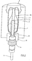
- the basic structure of a device for forming preforms (1) in container (2) is shown in FIG. 1 and in FIG. 2.
- the device for forming the container (2) consists essentially of a blowing station (3), which is provided with a blow mold (4) into which a preform (1) can be inserted.
- the preform (1) may be an injection-molded part of polyethylene terephthalate.
- the blow mold (4) consists of mold halves (5, 6) and a bottom part (7), which is a lifting device (8) is positionable.
- the preform (1) can be held in the region of the blowing station (3) by a transport mandrel (9) which, together with the preform (1), passes through a plurality of treatment stations within the device. But it is also possible to use the preform (1), for example via pliers or other handling means directly into the blow mold (4).
- a connecting piston (10) is arranged, which feeds the preform (1) compressed air and at the same time makes a seal relative to the transport mandrel (9).
- a connecting piston (10) is arranged, which feeds the preform (1) compressed air and at the same time makes a seal relative to the transport mandrel (9).
- a stretch rod (11) which is positioned by a cylinder (12).
- the use of curve segments is particularly useful when a plurality of blowing stations (3) are arranged on a rotating blowing wheel.
- a use of cylinders (12) is expedient if stationarily arranged blowing stations (3) are provided.
- the stretching system is designed such that a tandem arrangement of two cylinders (12) is provided. From a primary cylinder (13), the stretch rod (11) is first moved to the area of a bottom (14) of the preform (1) before the beginning of the actual stretching operation.
- the primary cylinder (13) with extended stretching rod together with a carriage (15) carrying the primary cylinder (13) is positioned by a secondary cylinder (16) or via a cam control.
- the secondary cylinder (16) in such a cam-controlled manner that a current stretching position is predetermined by a guide roller (17) which slides along a curved path during the execution of the stretching operation.
- the guide roller (17) is pressed by the secondary cylinder (16) against the guideway.
- the carriage (15) slides along two guide elements (18).
- Fig. 2 shows in addition to the blown container (2) and dashed lines drawn the preform (1) and schematically a developing container bladder (23).
- Fig. 3 shows the basic structure of a blow molding machine, with a heating section (24) and a rotating Blowing wheel (25) is provided.
- a preform input (26) the preforms (1) are transported by transfer wheels (27, 28, 29) into the region of the heating path (24).
- Heater (30) and fan (31) are arranged along the heating path (24) in order to temper the preforms (1).
- After a sufficient temperature control of the preforms (1) they are transferred to the blowing wheel (25), in the region of which the blowing stations (3) are arranged.
- the finished blown containers (2) are fed by further transfer wheels to a delivery line (32).
- thermoplastic material different plastics can be used.
- PET, PEN or PP can be used.
- the expansion of the preform (1) during the orientation process is carried out by compressed air supply.
- the compressed air supply is in a Vorblasphase in which gas, for example, compressed air, is supplied at a low pressure level and divided into a subsequent Hauptblasphase in which gas is supplied at a higher pressure level.
- compressed air is typically used at a pressure in the interval of 10 bar to 25 bar and during the main blowing phase compressed air is used supplied with a pressure in the interval from 25 bar to 40 bar.
- the heating section (24) from a plurality of revolving transport elements (33) is formed, which are strung together like a chain and guided by guide wheels (34).
- guide wheels (34) In particular, it is envisaged to open a substantially rectangular basic contour by the chain-like arrangement.
- a single relatively large-sized guide wheel (34) and in the region of adjacent deflections two comparatively smaller dimensioned guide wheels (36) used In principle, however, any other guides are conceivable.
- the arrangement shown to be particularly useful since in the region of the corresponding extent of the heating section (24) three deflecting wheels (34, 36) are positioned, and although in each case the smaller deflection wheels (36) in the region of the transition to the linear curves of the heating section (24) and the larger deflection wheel (34) in the immediate transfer area to the transfer wheel (29) and the input wheel (35).
- chain-like transport elements (33) it is also possible, for example, to use a rotating heating wheel.
- a larger amount of preforms (1) per unit time can be tempered by the larger number of radiant heaters (30).
- the fans (31) introduce cooling air into the region of cooling air ducts (39), which in each case oppose the associated radiant heaters (30) and emit the cooling air via outflow openings.
- a flow direction for the cooling air is realized substantially transversely to a transport direction of the preforms (1).
- the cooling air ducts (39) can provide reflectors for the heating radiation in the area opposite the radiant heaters (30), and it is likewise possible to realize cooling of the radiant heaters (30) via the discharged cooling air.
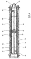
- FIG. 5 shows a rotary connection (40) for signal transmission, which has a ring-like constructed base element (41) and a in the illustrated embodiment above the base element arranged correspondence element (42).
- the rotary joint is designed as a slip ring rotary distributor.
- a non-contact rotary joint (40) in which one of the elements (41, 42) is formed as a transmitter and the other element (41, 42) as a receiver.
- the data transmission can take place without contact, for example optically or using electromagnetic waves.
- the base element (41) delimits a passage opening (43), in the region of which further components, not shown, can be arranged.
- the rotary joint (40) is arranged in the region of a carrying wheel designed as a blowing wheel (25).
- a supply element (44) which is designed as a rotary distributor for a liquid operating means.
- the correspondence element (42) is connected to a bus (45).
- Fig. 5 shows a vertically upper portion of the blowing wheel (25) shown in Fig. 3.
- the supply element (44) is designed here for supplying compressed air.
- a mounting plate (47) supports the co-rotating part of the supply element (44) and stabilizes longitudinal columns (48) of the blowing station (3). From the blowing stations (3) are each support elements (49) for the not recognizable in the drawing bottom parts (7) shown.
- the support members (49) are positioned using a cam control (50).
- the cam control (50) has cam rollers (51) which are positioned along a stationary cam (52).
- control box (53) which receives at least part of the electrical and electronic components required for control functions on the blowing wheel (25).
- the control box (53) is connected via a connecting line to the base member (41) of the rotary joint (40).
- the bus (45) consists of an Ethernet bus (55), a professional bus (56) and a USB bus (57).
- Ethernet bus (55) a bus that is connected to a PC or an Ethernet bus (55), a professional bus (56) and a USB bus (57).
- a USB bus a USB bus (57)
- the Ethernet bus (55) is used for data transmission with data rates of up to 100 Mbit / s. As a result, online connections to programming devices are made or data transmission to input / output modules is performed.
- the Profibus (56) is preferably used for data transmission at data rates up to 12.5 Mbit / s.
- a preferred application for data transfer occurs during data transfer to input and output modules.
- USB bus (57) is preferably carried out at data rates in the range of 1.5 to 480 Mbit / s.
- a typical application is in data transmission for data acquisition systems.
- the high capacities for data transmission provided by the bus (45) make it possible, in particular, to arrange only relatively few control components in the area of the control box (53) on the carrying wheel or even to completely dispense with the use of control components in this area.
- the arrangement of these components can instead be done in the stationary area of the device.
Landscapes
- Engineering & Computer Science (AREA)
- Manufacturing & Machinery (AREA)
- Mechanical Engineering (AREA)
- Blow-Moulding Or Thermoforming Of Plastics Or The Like (AREA)
- Multi-Process Working Machines And Systems (AREA)
- Arrangements For Transmission Of Measured Signals (AREA)
- Electrical Discharge Machining, Electrochemical Machining, And Combined Machining (AREA)
- Threshing Machine Elements (AREA)
Description
- Die Erfindung betrifft eine Vorrichtung zur Bearbeitung von Werkstücken, die ein rotierendes Tragrad aufweist, auf dem mindestens zwei Bearbeitungsstationen angeordnet sind und das mindestens eine Drehverbindung zur Signalübertragung aufweist, und bei der an die Drehverbindung mindestens ein Bus zur Datenübertragung angeschlossen ist.
- Derartige Drehverbindungen können zur Übertragung von elektrischer Energie, von Steuerungssignalen, von Meßsignalen oder von allgemeinen analogen oder digitalen Daten verwendet werden. Die Drehverbindungen sind beispielsweise als Schleifringdrehverteiler ausgebildet.
- Die einleitend genannten Vorrichtungen werden beispielsweise zur Herstellung von blasgeformten Behältern eingesetzt. Bei einer derartigen Behälterformung durch Blasdruckeinwirkung werden Vorformlinge aus einem thermoplastischen Material, beispielsweise Vorformlinge aus PET (Polyethylenterephthalat), innerhalb einer Blasmaschine unterschiedlichen Bearbeitungsstationen zugeführt. Typischerweise weist eine derartige Blasmaschine eine Heizeinrichtung sowie eine Blaseinrichtung auf, in deren Bereich der zuvor temperierte Vorformling durch biaxiale Orientierung zu einem Behälter expandiert wird. Die Expansion erfolgt mit Hilfe von Druckluft, die in den zu expandierenden Vorformling eingeleitet wird. Der verfahrenstechnische Ablauf bei einer derartigen Expansion des Vorformlings wird in der
DE-OS 43 40 291 erläutert. - Der grundsätzliche Aufbau einer Blasstation zur Behälterformung wird in der
DE-OS 42 12 583 beschrieben. Möglichkeiten zur Temperierung der Vorformlinge werden in derDE-OS 23 52 926 erläutert. - Innerhalb der Vorrichtung zur Blasformung können die Vorformlinge sowie die geblasenen Behälter mit Hilfe unterschiedlicher Handhabungseinrichtungen transportiert werden. Bewährt hat sich insbesondere die Verwendung von Transportdornen, auf die die Vorformlinge aufgesteckt werden. Die Vorformlinge können aber auch mit anderen Trageinrichtungen gehandhabt werden. Die Verwendung von Greifzangen zur Handhabung von Vorformlingen und die Verwendung von Spreizdornen, die zur Halterung in einen Mündungsbereich des Vorformlings einführbar sind, gehören ebenfalls zu den verfügbaren Konstruktionen.
- Die bereits erläuterte Handhabung der Vorformlinge erfolgt zum einen bei den sogenannten Zweistufenverfahren, bei denen die Vorformlinge zunächst in einem Spritzgußverfahren hergestellt, anschließend zwischengelagert und erst später hinsichtlich ihrer Temperatur konditioniert und zu einem Behälter aufgeblasen werden. Zum anderen erfolgt eine Anwendung bei den sogenannten Einstufenverfahren, bei denen die Vorformlinge unmittelbar nach ihrer spritzgußtechnischen Herstellung und einer ausreichenden Verfestigung geeignet temperiert und anschließend aufgeblasen werden.
- Im Hinblick auf die verwendeten Blasstationen sind unterschiedliche Ausführungsformen bekannt. Bei Blasstationen, die auf rotierenden Transporträdern angeordnet sind, ist eine buchartige Aufklappbarkeit der Formträger häufig anzutreffen. Es ist aber auch möglich, relativ zueinander verschiebliche oder andersartig geführte Formträger einzusetzen. Bei Blasstationen, die insbesondere dafür geeignet sind, mehrere Kavitäten zur Behälterformung aufzunehmen, werden neben aufklappbaren Formen auch parallel zueinander angeordnete Platten als Formträger verwendet.
- Aus der
EP-A-1 306 195 ist es bereits bekannt, auf einem rotierenden Blasrad angeordnete Blasstationen über eine Drehverbindung zur Signalübertragung an einen Bus zur Datenübertragung anzuschließen. Der Bus dient zur Übertragung von Prozeßdaten, die meßtechnisch im Bereich des Blasrades erfaßt wurden. - Die
US-B1-6,186,760 beschreibt ebenfalls eine Blasmaschine mit einem rotierenden Blasrad, auf dem Blasstationen angeordnet sind. Auf dem Blasrad erfaßte Prozeßdaten werden über eine Funkstrecke zu einem außerhalb des Blasrades angeordneten Computer übertragen. - In der
WO 03/078136 A - Die bislang verwendeten Drehverbindungen zur Signalübertragung sind sowohl auf dem Tragrad als auch im stationären Bereich der Maschine mit Leitungen zur Daten-, Energie- und Signalübertragung gekoppelt, die lediglich eine relativ geringe Übertragungsrate von Informationen pro Zeiteinheit zulassen. Diese begrenzten Möglichkeiten zur Datenübertragung reduzieren die Möglichkeiten zur Steuerung und Regelung der Vorrichtung, darüber hinaus wird auch der Benutzungskomfort reduziert, da nur eine begrenzte Anzeige von Meßwerten möglich ist. Darüber hinaus muß auch die gerätetechnische Struktur der verwendeten Steuerungs- und Regelungskomponenten an die verfügbaren Übertragungskapazitäten angepaßt werden.
- Aufgabe der vorliegenden Erfindung ist es, eine Vorrichtung der einleitend genannten Art derart zu konstruieren, daß eine vergrößerte Kapazität zur Datenübertragung bereitgestellt wird.
- Diese Aufgabe wird erfindungsgemäß dadurch gelöst, daß der Bus mindestens einen Ethernet-Bus aufweist und daß eine Steuerung für die Bearbeitungsstation mindestens teilweise stationär außerhalb des Tragrades angeordnet und über die Drehverbindung sowie über den Bus derart mit auf dem Tragrad angeordneten Aktoren im Bereich der Bearbeitungsstation verbunden ist, daß der Ethernet-Bus sowohl an ein stationäres Korrespondenzelement der Drehverbindung als auch an ein mit dem Tragrad verbundenes Basiselement der Drehverbindung angeschlossen ist.
- Die Verwendung des Bussystems zur Datenübertragung ermöglicht wesentlich erhöhte Datenübertragungsraten. Hierdurch können beispielsweise zu einem Bedienterminal erheblich mehr und aussagekräftigere Daten zu gemessenen Parametern, beispielsweise zu Druck, Temperatur und Positionierung von einzelnen Bauelementen, übertragen werden. Darüber hinaus ist es möglich, mindestens einen Teil der gemäß dem Stand der Technik auf dem Tragrad angeordneten Steuerungskomponenten im stationären Teil der Maschine anzuordnen und lediglich die Steuerungsinformationen zu den auf dem Tragrad angeordneten Aktoren zu übertragen. Der Aufbau des Tragrades kann hierdurch erheblich vereinfacht werden, darüber hinaus ergibt sich auf dem Tragrad auch eine erhebliche Platzeinsparung.
- Eine sehr hohe Datenübertragungsrate wird dadurch unterstützt, daß die Drehverbindung zur optischen Datenübertragung ausgebildet ist.
- Ebenfalls können hohe Datenübertragungsraten dadurch realisiert werden, daß die Drehverbindung zur Datenübertragung unter Verwendung elektromagnetischer Wellen ausgebildet ist.
- Eine verschleißarme Realisierung wird dadurch unterstützt, daß die Drehverbindung kontaktlos ausgebildet ist.
- Eine konstruktiv einfache Realisierung wird dadurch bereitgestellt, daß die Drehverbindung zur elektrischen Datenübertragung ausgebildet ist.
- Insbesondere ist daran gedacht, daß die Drehverbindung als ein Schleifring-Drehverteiler ausgebildet ist.
- Eine typische Ausführungsform wird dadurch definiert, daß der Bus zur elektrischen Datenübertragung ausgebildet ist.
- Zur Bereitstellung nochmals gesteigerter Datenübertragungsraten wird vorgeschlagen, daß der Bus zur optischen Datenübertragung ausgebildet ist.
- Für Datenübertragungsraten bis zu 100 Mbit/s erweist es sich als vorteilhaft, daß der Bus als ein Ethernet-Bus ausgebildet ist.
- Bei Datenübertragungsraten bis zu 12,5 Mbit/s wird vorgeschlagen, daß der Bus als ein Profibus ausgebildet ist.
- Zur Abdeckung eines sehr großen Spektrums an möglichen Datenübertragungsraten ist auch daran gedacht, daß der Bus als ein USB-Bus ausgebildet ist.
- Eine optimale Systemanpassung an gleichzeitig oder sequentiell auftretende unterschiedlich große Datenübertragungsraten erfolgt dadurch, daß der Bus mindestens einen Ethernet-Bus, mindestens einen Profibus sowie mindestens einen USB-Bus aufweist.
- Gemäß einer konstruktiven Variante ist vorgesehen, daß sich die Drehverbindung mindestens bereichsweise um Zuführleitungen eines versorgungselementes herumerstreckt.
- Gemäß einer bevorzugten Ausführungsform ist daran gedacht, daß die Bearbeitungsstationen zur Bearbeitung von Behältern ausgebildet sind.
- Insbesondere ist es möglich, daß die Bearbeitungsstationen zur Bearbeitung von thermoplastischen Behältern ausgebildet sind.
- Ein besonders bevorzugtes Anwendungsgebiet wird dadurch definiert, daß die Bearbeitungsstationen zur Bearbeitung von flaschenförmigen Behältern ausgebildet sind.
- Eine Anwendung bei Hochleistungsmaschinen kann dadurch erfolgen, daß das Tragrad als Rad einer Blasmaschine ausgebildet ist.
- Eine weitere Ausführungsvariante besteht darin, daß das Tragrad als Rad einer Plasmabeschichtungsmaschine ausgebildet ist.
- Ein weiteres Anwendungsgebiet wird dadurch erschlossen, daß das Tragrad als Rad einer Füllmaschine ausgebildet ist.
- Eine Reduktion der rotierenden Masse im Bereich des Tragrades kann dadurch erfolgen, daß eine Steuerung für die Bearbeitungsstation mindestens teilweise stationär außerhalb des Tragrades angeordnet und über die Drehverbindung sowie über den Bus mit Aktoren im Bereich der Bearbeitungsstation verbunden ist.
- Darüber hinaus erweist es sich als vorteilhaft, daß eine Steuerung für die Bearbeitungsstation mindestens teilweise stationär außerhalb des Tragrades angeordnet und über die Drehverbindung sowie über den Bus mit Sensoren im Bereich der Bearbeitungsstation verbunden ist.
- In den Zeichnungen sind Ausführungsbeispiele der Erfindung schematisch dargestellt. Es zeigen:
- Fig. 1
- Eine perspektivische Darstellung einer Blasstation zur Herstellung von Behältern aus Vorformlingen,
- Fig. 2
- einen Längsschnitt durch eine Blasform, in der ein Vorformling gereckt und expandiert wird,
- Fig. 3
- eine Skizze zur Veranschaulichung eines grundsätzlichen Aufbaus einer Vorrichtung zur Blasformung von Behältern,
- Fig. 4
- eine modifizierte Heizstrecke mit vergrößerter Heizkapazität und
- Fig. 5
- eine Seitenansicht einer kombinierten Anordnung eines Versorgungselementes sowie einer Drehverbindung zur Signalübertragung mit angeschlossenem Bussystem im Bereich eines rotationsfähigen Tragrades.
- Eine Anwendung der Drehverbindung zur Signalübertragung kann beispielsweise bei einer Vorrichtung zur Blasformung erfolgen. Der prinzipielle Aufbau einer Vorrichtung zur Umformung von Vorformlingen (1) in Behälter (2) ist in Fig. 1 und in Fig. 2 dargestellt.
- Die Vorrichtung zur Formung des Behälters (2) besteht im wesentlichen aus einer Blasstation (3), die mit einer Blasform (4) versehen ist, in die ein Vorformling (1) einsetzbar ist. Der Vorformling (1) kann ein spritzgegossenes Teil aus Polyethylenterephthalat sein. Zur Ermöglichung eines Einsetzens des Vorformlings (1) in die Blasform (4) und zur Ermöglichung eines Herausnehmens des fertigen Behälters (2) besteht die Blasform (4) aus Formhälften (5, 6) und einem Bodenteil (7), das von einer Hubvorrichtung (8) positionierbar ist. Der Vorformling (1) kann im Bereich der Blasstation (3) von einem Transportdorn (9) gehalten sein, der gemeinsam mit dem Vorformling (1) eine Mehrzahl von Behandlungsstationen innerhalb der Vorrichtung durchläuft. Es ist aber auch möglich, den Vorformling (1) beispielsweise über Zangen oder andere Handhabungsmittel direkt in die Blasform (4) einzusetzen.
- Zur Ermöglichung einer Druckluftzuleitung ist unterhalb des Transportdornes (9) ein Anschlußkolben (10) angeordnet, der dem Vorformling (1) Druckluft zuführt und gleichzeitig eine Abdichtung relativ zum Transportdorn (9) vornimmt. Bei einer abgewandelten Konstruktion ist es grundsätzlich aber auch denkbar, feste Druckluftzuleitungen zu verwenden.
- Eine Reckung des Vorformlings (1) erfolgt mit Hilfe einer Reckstange (11), die von einem Zylinder (12) positioniert wird. Grundsätzlich ist es aber auch denkbar, eine mechanische Positionierung der Reckstange (11) über Kurvensegmente durchzuführen, die von Abgriffrollen beaufschlagt sind. Die Verwendung von Kurvensegmenten ist insbesondere dann zweckmäßig, wenn eine Mehrzahl von Blasstationen (3) auf einem rotierenden Blasrad angeordnet sind. Eine Verwendung von Zylindern (12) ist zweckmäßig, wenn ortsfest angeordnete Blasstationen (3) vorgesehen sind.
- Bei der in Fig. 1 dargestellten Ausführungsform ist das Recksystem derart ausgebildet, daß eine Tandem-Anordnung von zwei Zylindern (12) bereitgestellt ist. Von einem Primärzylinder (13) wird die Reckstange (11) zunächst vor Beginn des eigentlichen Reckvorganges bis in den Bereich eines Bodens (14) des Vorformlings (1) gefahren. Während des eigentlichen Reckvorganges wird der Primärzylinder (13) mit ausgefahrener Reckstange gemeinsam mit einem den Primärzylinder (13) tragenden Schlitten (15) von einem Sekundärzylinder (16) oder über eine Kurvensteuerung positioniert. Insbesondere ist daran gedacht, den Sekundärzylinder (16) derart kurvengesteuert einzusetzen, daß von einer Führungsrolle (17), die während der Durchführung des Reckvorganges an einer Kurvenbahn entlang gleitet, eine aktuelle Reckposition vorgegeben wird. Die Führungsrolle (17) wird vom Sekundärzylinder (16) gegen die Führungsbahn gedrückt. Der Schlitten (15) gleitet entlang von zwei Führungselementen (18).
- Nach einem Schließen der im Bereich von Trägern (19, 20) angeordneten Formhälften (5, 6) erfolgt eine verriegelung der Träger (19, 20) relativ zueinander mit Hilfe einer verriegelungseinrichtung (20).
- Zur Anpassung an unterschiedliche Formen eines Mündungsabschnittes (21) des Vorformlings (1) ist gemäß Fig. 2 die Verwendung separater Gewindeeinsätze (22) im Bereich der Blasform (4) vorgesehen.
- Fig. 2 zeigt zusätzlich zum geblasenen Behälter (2) auch gestrichelt eingezeichnet den Vorformling (1) und schematisch eine sich entwickelnde Behälterblase (23).
- Fig. 3 zeigt den grundsätzlichen Aufbau einer Blasmaschine, die mit einer Heizstrecke (24) sowie einem rotierenden Blasrad (25) versehen ist. Ausgehend von einer Vorformlingseingabe (26) werden die Vorformlinge (1) von Übergaberädern (27, 28, 29) in den Bereich der Heizstrecke (24) transportiert. Entlang der Heizstrecke (24) sind Heizstrahler (30) sowie Gebläse (31) angeordnet, um die Vorformlinge (1) zu temperieren. Nach einer ausreichenden Temperierung der Vorformlinge (1) werden diese an das Blasrad (25) übergeben, in dessen Bereich die Blasstationen (3) angeordnet sind. Die fertig geblasenen Behälter (2) werden von weiteren Übergaberädern einer Ausgabestrecke (32) zugeführt.
- Um einen Vorformling (1) derart in einen Behälter (2) umformen zu können, daß der Behälter (2) Materialeigenschaften aufweist, die eine lange Verwendungsfähigkeit von innerhalb des Behälters (2) abgefüllten Lebensmitteln, insbesondere von Getränken, gewährleisten, müssen spezielle Verfahrensschritte bei der Beheizung und Orientierung der Vorformlinge (1) eingehalten werden. Darüber hinaus können vorteilhafte Wirkungen durch Einhaltung spezieller Dimensionierungsvorschriften erzielt werden.
- Als thermoplastisches Material können unterschiedliche Kunststoffe verwendet werden. Einsatzfähig sind beispielsweise PET, PEN oder PP.
- Die Expansion des Vorformlings (1) während des Orientierungsvorganges erfolgt durch Druckluftzuführung. Die Druckluftzuführung ist in eine Vorblasphase, in der Gas, zum Beispiel Preßluft, mit einem niedrigen Druckniveau zugeführt wird und in eine sich anschließende Hauptblasphase unterteilt, in der Gas mit einem höheren Druckniveau zugeführt wird. Während der Vorblasphase wird typischerweise Druckluft mit einem Druck im Intervall von 10 bar bis 25 bar verwendet und während der Hauptblasphase wird Druckluft mit einem Druck im Intervall von 25 bar bis 40 bar zugeführt.
- Aus Fig. 3 ist ebenfalls erkennbar, daß bei der dargestellten Ausführungsform die Heizstrecke (24) aus einer Vielzahl umlaufender Transportelemente (33) ausgebildet ist, die kettenartig aneinandergereiht und entlang von Umlenkrädern (34) geführt sind. Insbesondere ist daran gedacht, durch die kettenartige Anordnung eine im wesentlichen rechteckförmige Grundkontur aufzuspannen. Bei der dargestellten Ausführungsform werden im Bereich der dem Übergaberad (29) und einem Eingaberad (35) zugewandten Ausdehnung der Heizstrecke (24) ein einzelnes relativ groß dimensioniertes Umlenkrad (34) und im Bereich von benachbarten Umlenkungen zwei vergleichsweise kleiner dimensionierte Umlenkräder (36) verwendet. Grundsätzlich sind aber auch beliebige andere Führungen denkbar.
- Zur Ermöglichung einer möglichst dichten Anordnung des Übergaberades (29) und des Eingaberades (35) relativ zueinander erweist sich die dargestellte Anordnung als besonders zweckmäßig, da im Bereich der entsprechenden Ausdehnung der Heizstrecke (24) drei Umlenkräder (34, 36) positioniert sind, und zwar jeweils die kleineren Umlenkräder (36) im Bereich der Überleitung zu den linearen Verläufen der Heizstrecke (24) und das größere Umlenkrad (34) im unmittelbaren Übergabebereich zum Übergaberad (29) und zum Eingaberad (35). Alternativ zur Verwendung von kettenartigen Transportelementen (33) ist es beispielsweise auch möglich, ein rotierendes Heizrad zu verwenden.
- Nach einem fertigen Blasen der Behälter (2) werden diese von einem Entnahmerad (37) aus dem Bereich der Blasstationen (3) herausgeführt und über das Übergaberad (28) und ein Ausgaberad (38) zur Ausgabestrecke (32) transportiert.
- In der in Fig. 4 dargestellten modifizierten Heizstrecke (24) können durch die größere Anzahl von Heizstrahlern (30) eine größere Menge von Vorformlingen (1) je Zeiteinheit temperiert werden. Die Gebläse (31) leiten hier Kühlluft in den Bereich von Kühlluftkanälen (39) ein, die den zugeordneten Heizstrahlern (30) jeweils gegenüberliegen und über Ausströmöffnungen die Kühlluft abgeben. Durch die Anordnung der Ausströmrichtungen wird eine Strömungsrichtung für die Kühlluft im wesentlichen quer zu einer Transportrichtung der Vorformlinge (1) realisiert. Die Kühlluftkanäle (39) können im Bereich von den Heizstrahlern (30) gegenüberliegenden Oberflächen Reflektoren für die Heizstrahlung bereitstellen, ebenfalls ist es möglich, über die abgegebene Kühlluft auch eine Kühlung der Heizstrahler (30) zu realisieren.
- Fig. 5 zeigt eine Drehverbindung (40) zur Signalübertragung, die ein ringartig konstruiertes Basiselement (41) sowie ein beim dargestellten Ausführungsbeispiel oberhalb des Basiselementes angeordnetes Korrespondenzelement (42) aufweist. Die Drehverbindung ist als ein Schleifringdrehverteiler ausgebildet. Alternativ ist auch die Verwendung einer kontaktlosen Drehverbindung (40) möglich, bei der eines der Elemente (41, 42) als ein Sender und das andere Element (41, 42) als ein Empfänger ausgebildet ist. Die Datenübertragung kann kontaktlos beispielsweise optisch oder unter Verwendung von elektromagnetischen Wellen erfolgen. Das Basiselement (41) begrenzt eine Durchgangsöffnung (43), in deren Bereich nicht dargestellte weitere Bauelemente angeordnet werden können.
- Bei der Ausführungsform gemäß Fig. 5 ist die Drehverbindung (40) im Bereich eines als Blasrad (25) ausgebildeten Tragrades angeordnet. Im Bereich der Durchgangsöffnung (43) des Basiselementes (41) ist bei diesem Ausführungsbeispiel ein Versorgungselement (44) angeordnet, das als ein Drehverteiler für ein flüssiges Betriebsmittel ausgebildet ist. Das Korrespondenzelement (42) ist an einen Bus (45) angeschlossen.
- Fig. 5 zeigt einen in lotrechter Richtung oberen Bereich des in Fig. 3 dargestellten Blasrades (25). Das Versorgungselement (44) ist hier zur Zuführung von Druckluft ausgebildet. Eine Montageplatte (47) haltert den mitrotierenden Teil des Versorgungselementes (44) und stabilisiert Längssäulen (48) der Blasstation (3). Von den Blasstationen (3) sind jeweils Tragelemente (49) für die in der Zeichnung nicht mehr erkennbaren Bodenteile (7) dargestellt. Die Tragelemente (49) werden unter Verwendung einer Kurvensteuerung (50) positioniert. Die Kurvensteuerung (50) weist hierzu Kurvenrollen (51) auf, die entlang einer ortsfest angeordneten Steuerkurve (52) positioniert werden.
- Zu erkennen ist in Fig. 5 ebenfalls ein Steuerungskasten (53), der wenigstens einen Teil der für Steuerfunktionen auf dem Blasrad (25) erforderlichen elektrischen und elektronischen Komponenten aufnimmt. Der Steuerungskasten (53) ist über eine Verbindungsleitung an das Basiselement (41) der Drehverbindung (40) angeschlossen.
- Gemäß dem Ausführungsbeispiel in Fig. 5 besteht der Bus (45) aus einem Ethernet-Bus (55), einem Profi-Bus (56) sowie einem USB-Bus (57). Grundsätzlich ist es auch denkbar, den Bus (45) nur aus einem einzelnen der Bussysteme (55, 56, 57) oder aus einer Kombination von zwei dieser Bussysteme zu realisieren. Ebenfalls ist es denkbar, den Bus (45) um zusätzliche Buskomponenten zur jeweils gewählten Gesamt- oder Teilkombination zu erweitern.
- Der Ethernet-Bus (55) dient zu einer Datenübertragung mit Datenraten bis zu 100 Mbit/s. Es werden hierdurch Online-Verbindungen zu Programmiergeräten hergestellt oder eine Datenübertragung zu Eingabe/Ausgabe-Modulen durchgeführt.
- Der Profibus (56) dient vorzugsweise zu einer Datenübertragung mit Datenraten bis zu 12,5 Mbit/s. Eine bevorzugte Anwendung bei der Datenübertragung erfolgt bei der Datenübertragung zu Eingabe- und Ausgabemodulen.
- Die Verwendung des USB-Busses (57) erfolgt bevorzugt bei Datenraten im Bereich von 1,5 bis zu 480 Mbit/s. Eine typische Anwendung erfolgt bei der Datenübertragung für Meßwerterfassungssysteme.
- Die durch den Bus (45) bereitgestellten hohen Kapazitäten zur Datenübertragung ermöglichen es insbesondere, im Bereich des Steuerungskastens (53) auf dem Tragrad nur relativ wenige Steuerungskomponenten anzuordnen oder auf die Verwendung von Steuerungskomponenten in diesem Bereich sogar vollständig zu verzichten. Die Anordnung dieser Komponenten kann statt dessen im stationären Bereich der Vorrichtung erfolgen.
Claims (19)
- Vorrichtung zur Bearbeitung von Werkstücken, die ein rotierendes Tragrad aufweist, auf dem mindestens zwei Bearbeitungsstationen angeordnet sind und das mindestens eine Drehverbindung (40) zur Signalübertragung aufweist, und bei der an die Drehverbindung (40) mindestens ein Bus (45) zur Datenübertragung angeschlossen ist, dadurch gekennzeichnet, daß der Bus (45) mindestens einen Ethernet-Bus aufweist und daß eine Steuerung für die Bearbeitungsstation mindestens teilweise stationär außerhalb des Tragrades angeordnet und über die Drehverbindung (40) sowie über den Bus derart mit auf dem Tragrad angeordneten Aktoren im Bereich der Bearbeitungsstation verbunden ist, daß der Ethernet-Bus sowohl an ein stationäres Korrespondenzelement (42) der Drehverbindung (40) als auch an ein mit dem Tragrad verbundenes Basiselement (41) der Drehverbindung (40) angeschlossen ist.
- Vorrichtung nach Anspruch 1, dadurch gekennzeichnet, daß die Drehverbindung (40) zur optischen Datenübertragung ausgebildet ist.
- Vorrichtung nach Anspruch 1, dadurch gekennzeichnet, daß die Drehverbindung (40) zur Datenübertragung unter Verwendung elektromagnetischer Wellen ausgebildet ist.
- Vorrichtung nach Anspruch 1, dadurch gekennzeichnet, daß die Drehverbindung (40) kontaktlos ausgebildet ist.
- Vorrichtung nach Anspruch 1, dadurch gekennzeichnet, daß die Drehverbindung (40) zur elektrischen Datenübertragung ausgebildet ist.
- Vorrichtung nach Anspruch 1, dadurch gekennzeichnet, daß die Drehverbindung (40) als ein Schleifring-Drehverteiler ausgebildet ist.
- Vorrichtung nach einem der Ansprüche 1 bis 6, dadurch gekennzeichnet, daß der Bus (45) zur elektrischen Datenübertragung ausgebildet ist.
- Vorrichtung nach einem der Ansprüche 1 bis 6, dadurch gekennzeichnet, daß der Bus (45) zur optischen Datenübertragung ausgebildet ist.
- Vorrichtung nach einem der Ansprüche 1 bis 8, dadurch gekennzeichnet, daß der Bus (45) einen Profibus (56) aufweist.
- Vorrichtung nach einem der Ansprüche 1 bis 8, dadurch gekennzeichnet, daß der Bus (45) einen USB-Bus (57) aufweist.
- Vorrichtung nach einem der Ansprüche 1 bis 8, dadurch gekennzeichnet, daß der Bus (45) mindestens einen Ethernet-Bus (55), mindestens einen Profibus (56) sowie mindestens einen USB-Bus (57) aufweist.
- Vorrichtung nach einem der Ansprüche 1 bis 11, dadurch gekennzeichnet, daß sich die Drehverbindung (40) mindestens bereichsweise um Zuführleitungen eines Versorgungselementes (44) herumerstreckt.
- Vorrichtung nach einem der Ansprüche 1 bis 12, dadurch gekennzeichnet, daß die Bearbeitungsstationen zur Bearbeitung von Behältern ausgebildet sind.
- Vorrichtung nach einem der Ansprüche 1 bis 12, dadurch gekennzeichnet, daß die Bearbeitungsstationen zur Bearbeitung von thermoplastischen Behältern ausgebildet sind.
- Vorrichtung nach einem der Ansprüche 1 bis 12, dadurch gekennzeichnet, daß die Bearbeitungsstationen zur Bearbeitung von flaschenförmigen Behältern ausgebildet sind.
- Vorrichtung nach einem der Ansprüche 1 bis 15, dadurch gekennzeichnet, daß das Tragrad als Rad einer Blasmaschine ausgebildet ist.
- Vorrichtung nach einem der Ansprüche 1 bis 15, dadurch gekennzeichnet, daß das Tragrad als Rad einer Plasmabeschichtungsmaschine ausgebildet ist.
- Vorrichtung nach einem der Ansprüche 1 bis 15, dadurch gekennzeichnet, daß das Tragrad als Rad einer Füllmaschine ausgebildet ist.
- Vorrichtung nach einem der Ansprüche 1 bis 18, dadurch gekennzeichnet, daß eine Steuerung für die Bearbeitungsstation mindestens teilweise stationär außerhalb des Tragrades angeordnet und über die Drehverbindung (40) sowie über den Bus mit Sensoren im Bereich der Bearbeitungsstation verbunden ist.
Applications Claiming Priority (2)
| Application Number | Priority Date | Filing Date | Title |
|---|---|---|---|
| DE102004008400 | 2004-02-20 | ||
| DE102004008400A DE102004008400A1 (de) | 2004-02-20 | 2004-02-20 | Vorrichtung zur Bearbeitung von Werkstücken |
Publications (3)
| Publication Number | Publication Date |
|---|---|
| EP1566258A2 EP1566258A2 (de) | 2005-08-24 |
| EP1566258A3 EP1566258A3 (de) | 2005-11-09 |
| EP1566258B1 true EP1566258B1 (de) | 2007-10-31 |
Family
ID=34706874
Family Applications (1)
| Application Number | Title | Priority Date | Filing Date |
|---|---|---|---|
| EP05000444A Revoked EP1566258B1 (de) | 2004-02-20 | 2005-01-12 | Vorrichtung zur Bearbeitung von Werkstücken |
Country Status (3)
| Country | Link |
|---|---|
| EP (1) | EP1566258B1 (de) |
| AT (1) | ATE376921T1 (de) |
| DE (2) | DE102004008400A1 (de) |
Cited By (1)
| Publication number | Priority date | Publication date | Assignee | Title |
|---|---|---|---|---|
| US12170849B2 (en) | 2022-02-04 | 2024-12-17 | Applied Materials, Inc. | Pulsed illumination for fluid inspection |
Families Citing this family (5)
| Publication number | Priority date | Publication date | Assignee | Title |
|---|---|---|---|---|
| FR2872081B1 (fr) * | 2004-06-28 | 2006-10-06 | Sidel Sas | Machine tournante a colonne tournante d'alimentation electrique et fluidique |
| EP1996385B1 (de) * | 2006-03-20 | 2011-10-05 | Eugen Seitz Ag | Blasstation für streckblasmaschinen |
| DE102015206172A1 (de) * | 2015-04-07 | 2016-10-13 | Krones Ag | Vorrichtung in der Getränkemittelindustrie mit wechselbarem und/oder rotierbarem Maschinenmodul |
| DE102016203762A1 (de) | 2016-03-08 | 2017-09-14 | Krones Ag | Schleifringübertrager für Rundläufermaschinen |
| DE102022120823A1 (de) * | 2022-08-17 | 2024-02-22 | Krones Aktiengesellschaft | Vorrichtung und Verfahren zum Inspizieren von Behältnissen |
Family Cites Families (6)
| Publication number | Priority date | Publication date | Assignee | Title |
|---|---|---|---|---|
| DE2352926A1 (de) * | 1973-10-22 | 1975-04-24 | Heidenreich & Harbeck Gmbh | Verfahren und vorrichtung zum erwaermen eines werkstueckes aus kunststoff |
| US6186760B1 (en) * | 1997-08-01 | 2001-02-13 | Greig S. Latham | Blow mold machine monitor and control system |
| DE19909307A1 (de) * | 1998-03-19 | 1999-09-23 | Siemens Ag | Produktionsmaschine mit elektrischen Antrieben für den Einsatz in der Kunststoffindustrie |
| DE20122799U1 (de) * | 2001-03-06 | 2010-06-10 | Siemens Ag | Industrielles Datenübertragungssystem |
| DE10153045A1 (de) * | 2001-10-26 | 2003-05-08 | Sig Corpoplast Gmbh & Co Kg | Verfahren und Vorrichtung zur Steuerung eines Blasvorganges |
| DE10231345A1 (de) * | 2002-03-18 | 2003-10-16 | Tetra Laval Holdings & Finance | Vorrichtung zur Herstellung von Kunstoffbehältern mittels Streckblasformen und Vorrichtung zum Beschichten der Innenwände eines Kunstoffbehälters |
-
2004
- 2004-02-20 DE DE102004008400A patent/DE102004008400A1/de not_active Withdrawn
-
2005
- 2005-01-12 DE DE502005001800T patent/DE502005001800D1/de not_active Expired - Lifetime
- 2005-01-12 AT AT05000444T patent/ATE376921T1/de active
- 2005-01-12 EP EP05000444A patent/EP1566258B1/de not_active Revoked
Cited By (1)
| Publication number | Priority date | Publication date | Assignee | Title |
|---|---|---|---|---|
| US12170849B2 (en) | 2022-02-04 | 2024-12-17 | Applied Materials, Inc. | Pulsed illumination for fluid inspection |
Also Published As
| Publication number | Publication date |
|---|---|
| ATE376921T1 (de) | 2007-11-15 |
| EP1566258A3 (de) | 2005-11-09 |
| DE502005001800D1 (de) | 2007-12-13 |
| EP1566258A2 (de) | 2005-08-24 |
| DE102004008400A1 (de) | 2005-09-08 |
Similar Documents
| Publication | Publication Date | Title |
|---|---|---|
| EP1998950B1 (de) | Verfahren und vorrichtung zur blasformung von behältern unter verwendung von wanddickenmessung des geformten gegenstandes | |
| EP2144742B1 (de) | Vorrichtung zur blasformung von behältern | |
| EP2429795B1 (de) | Verfahren und vorrichtung zur blasformung sowie zum befüllen von behältern | |
| EP2307185B1 (de) | Verfahren und vorrichtung zur blasformung von behältern | |
| EP1910056B1 (de) | Verfahren und vorrichtung zur positionierung eines bauelementes | |
| EP2276621B1 (de) | Verfahren und vorrichtung zur blasformung von behältern | |
| DE102007016027A1 (de) | Verfahren und Vorrichtung zur Blasformung von Behältern | |
| EP1566258B1 (de) | Vorrichtung zur Bearbeitung von Werkstücken | |
| EP1226017B1 (de) | Verfahren und vorrichtung zur blasformung von behältern | |
| DE10214787A1 (de) | Vorrichtung zur Handhabung von Werkstücken | |
| EP1520681B2 (de) | Vorrichtung zur Blasformung von Behältern | |
| EP2694270B1 (de) | Vorrichtung zur blasformung von behältern | |
| EP1574318B1 (de) | Verfahren und Vorrichtung zur Blasformung von Behältern | |
| WO2006108382A1 (de) | Verfahren und vorrichtung zur blasformung von behältern unter verwendung eines beweglich geführten ventilträgers | |
| EP1297942B1 (de) | Vorrichtung zur Handhabung von streckgeblasenen Behältern mittels Übergaberad, wobei ein Halteelement relativ drehbar zum Tragarm angeordnet ist und über eine Steuerkurve verstellbar ist | |
| EP1473139B1 (de) | Verfahren und Vorrichtung zur Blasformung von Behältern | |
| WO2007033631A2 (de) | Verfahren und vorrichtung zur blasformung von behältern mit einer gesteuerten reckstange | |
| DE10361782B4 (de) | Vorrichtung zur Bearbeitung von Werkstücken | |
| EP1968778A2 (de) | Verfahren und vorrichtung zur blasformung von behältern | |
| DE102005000681A1 (de) | Vefahren und Vorrichtung zur Blasformung von Behältern | |
| DE102006004940A1 (de) | Verfahren und Vorrichtung zur Blasformung von Behältern | |
| WO2001039958A1 (de) | Verfahren und vorrichtung zur blasformung von behältern | |
| WO2013056753A1 (de) | Vorrichtung zur halterung von werkstücken |
Legal Events
| Date | Code | Title | Description |
|---|---|---|---|
| PUAI | Public reference made under article 153(3) epc to a published international application that has entered the european phase |
Free format text: ORIGINAL CODE: 0009012 |
|
| AK | Designated contracting states |
Kind code of ref document: A2 Designated state(s): AT BE BG CH CY CZ DE DK EE ES FI FR GB GR HU IE IS IT LI LT LU MC NL PL PT RO SE SI SK TR |
|
| AX | Request for extension of the european patent |
Extension state: AL BA HR LV MK YU |
|
| PUAL | Search report despatched |
Free format text: ORIGINAL CODE: 0009013 |
|
| AK | Designated contracting states |
Kind code of ref document: A3 Designated state(s): AT BE BG CH CY CZ DE DK EE ES FI FR GB GR HU IE IS IT LI LT LU MC NL PL PT RO SE SI SK TR |
|
| AX | Request for extension of the european patent |
Extension state: AL BA HR LV MK YU |
|
| 17P | Request for examination filed |
Effective date: 20051012 |
|
| AKX | Designation fees paid |
Designated state(s): AT BE BG CH CY CZ DE DK EE ES FI FR GB GR HU IE IS IT LI LT LU MC NL PL PT RO SE SI SK TR |
|
| 17Q | First examination report despatched |
Effective date: 20051208 |
|
| GRAP | Despatch of communication of intention to grant a patent |
Free format text: ORIGINAL CODE: EPIDOSNIGR1 |
|
| GRAS | Grant fee paid |
Free format text: ORIGINAL CODE: EPIDOSNIGR3 |
|
| GRAA | (expected) grant |
Free format text: ORIGINAL CODE: 0009210 |
|
| AK | Designated contracting states |
Kind code of ref document: B1 Designated state(s): AT BE BG CH CY CZ DE DK EE ES FI FR GB GR HU IE IS IT LI LT LU MC NL PL PT RO SE SI SK TR |
|
| REG | Reference to a national code |
Ref country code: GB Ref legal event code: FG4D Free format text: NOT ENGLISH |
|
| REG | Reference to a national code |
Ref country code: IE Ref legal event code: FG4D Free format text: LANGUAGE OF EP DOCUMENT: GERMAN |
|
| REG | Reference to a national code |
Ref country code: CH Ref legal event code: EP |
|
| REF | Corresponds to: |
Ref document number: 502005001800 Country of ref document: DE Date of ref document: 20071213 Kind code of ref document: P |
|
| NLV1 | Nl: lapsed or annulled due to failure to fulfill the requirements of art. 29p and 29m of the patents act | ||
| PG25 | Lapsed in a contracting state [announced via postgrant information from national office to epo] |
Ref country code: ES Free format text: LAPSE BECAUSE OF FAILURE TO SUBMIT A TRANSLATION OF THE DESCRIPTION OR TO PAY THE FEE WITHIN THE PRESCRIBED TIME-LIMIT Effective date: 20080211 Ref country code: NL Free format text: LAPSE BECAUSE OF FAILURE TO SUBMIT A TRANSLATION OF THE DESCRIPTION OR TO PAY THE FEE WITHIN THE PRESCRIBED TIME-LIMIT Effective date: 20071031 Ref country code: SE Free format text: LAPSE BECAUSE OF FAILURE TO SUBMIT A TRANSLATION OF THE DESCRIPTION OR TO PAY THE FEE WITHIN THE PRESCRIBED TIME-LIMIT Effective date: 20080131 |
|
| GBV | Gb: ep patent (uk) treated as always having been void in accordance with gb section 77(7)/1977 [no translation filed] | ||
| PG25 | Lapsed in a contracting state [announced via postgrant information from national office to epo] |
Ref country code: PL Free format text: LAPSE BECAUSE OF FAILURE TO SUBMIT A TRANSLATION OF THE DESCRIPTION OR TO PAY THE FEE WITHIN THE PRESCRIBED TIME-LIMIT Effective date: 20071031 Ref country code: PT Free format text: LAPSE BECAUSE OF FAILURE TO SUBMIT A TRANSLATION OF THE DESCRIPTION OR TO PAY THE FEE WITHIN THE PRESCRIBED TIME-LIMIT Effective date: 20080331 Ref country code: BG Free format text: LAPSE BECAUSE OF FAILURE TO SUBMIT A TRANSLATION OF THE DESCRIPTION OR TO PAY THE FEE WITHIN THE PRESCRIBED TIME-LIMIT Effective date: 20080131 Ref country code: IS Free format text: LAPSE BECAUSE OF FAILURE TO SUBMIT A TRANSLATION OF THE DESCRIPTION OR TO PAY THE FEE WITHIN THE PRESCRIBED TIME-LIMIT Effective date: 20080229 Ref country code: LT Free format text: LAPSE BECAUSE OF FAILURE TO SUBMIT A TRANSLATION OF THE DESCRIPTION OR TO PAY THE FEE WITHIN THE PRESCRIBED TIME-LIMIT Effective date: 20071031 Ref country code: SI Free format text: LAPSE BECAUSE OF FAILURE TO SUBMIT A TRANSLATION OF THE DESCRIPTION OR TO PAY THE FEE WITHIN THE PRESCRIBED TIME-LIMIT Effective date: 20071031 |
|
| REG | Reference to a national code |
Ref country code: IE Ref legal event code: FD4D |
|
| ET | Fr: translation filed | ||
| BERE | Be: lapsed |
Owner name: SIG TECHNOLOGY LTD. Effective date: 20080131 |
|
| PG25 | Lapsed in a contracting state [announced via postgrant information from national office to epo] |
Ref country code: DK Free format text: LAPSE BECAUSE OF FAILURE TO SUBMIT A TRANSLATION OF THE DESCRIPTION OR TO PAY THE FEE WITHIN THE PRESCRIBED TIME-LIMIT Effective date: 20071031 Ref country code: CZ Free format text: LAPSE BECAUSE OF FAILURE TO SUBMIT A TRANSLATION OF THE DESCRIPTION OR TO PAY THE FEE WITHIN THE PRESCRIBED TIME-LIMIT Effective date: 20071031 |
|
| PLBI | Opposition filed |
Free format text: ORIGINAL CODE: 0009260 |
|
| PLBI | Opposition filed |
Free format text: ORIGINAL CODE: 0009260 |
|
| PG25 | Lapsed in a contracting state [announced via postgrant information from national office to epo] |
Ref country code: SK Free format text: LAPSE BECAUSE OF FAILURE TO SUBMIT A TRANSLATION OF THE DESCRIPTION OR TO PAY THE FEE WITHIN THE PRESCRIBED TIME-LIMIT Effective date: 20071031 Ref country code: RO Free format text: LAPSE BECAUSE OF FAILURE TO SUBMIT A TRANSLATION OF THE DESCRIPTION OR TO PAY THE FEE WITHIN THE PRESCRIBED TIME-LIMIT Effective date: 20071031 Ref country code: MC Free format text: LAPSE BECAUSE OF NON-PAYMENT OF DUE FEES Effective date: 20080131 |
|
| PLAX | Notice of opposition and request to file observation + time limit sent |
Free format text: ORIGINAL CODE: EPIDOSNOBS2 |
|
| 26 | Opposition filed |
Opponent name: SCHLEIFRING UND APPARATEBAU GMBH Effective date: 20080724 |
|
| 26 | Opposition filed |
Opponent name: SCHLEIFRING UND APPARATEBAU GMBH Effective date: 20080724 Opponent name: KRONES AG Effective date: 20080731 |
|
| PLAB | Opposition data, opponent's data or that of the opponent's representative modified |
Free format text: ORIGINAL CODE: 0009299OPPO |
|
| PG25 | Lapsed in a contracting state [announced via postgrant information from national office to epo] |
Ref country code: IE Free format text: LAPSE BECAUSE OF FAILURE TO SUBMIT A TRANSLATION OF THE DESCRIPTION OR TO PAY THE FEE WITHIN THE PRESCRIBED TIME-LIMIT Effective date: 20071031 |
|
| PG25 | Lapsed in a contracting state [announced via postgrant information from national office to epo] |
Ref country code: GB Free format text: LAPSE BECAUSE OF FAILURE TO SUBMIT A TRANSLATION OF THE DESCRIPTION OR TO PAY THE FEE WITHIN THE PRESCRIBED TIME-LIMIT Effective date: 20071031 |
|
| PG25 | Lapsed in a contracting state [announced via postgrant information from national office to epo] |
Ref country code: GR Free format text: LAPSE BECAUSE OF FAILURE TO SUBMIT A TRANSLATION OF THE DESCRIPTION OR TO PAY THE FEE WITHIN THE PRESCRIBED TIME-LIMIT Effective date: 20080201 Ref country code: EE Free format text: LAPSE BECAUSE OF FAILURE TO SUBMIT A TRANSLATION OF THE DESCRIPTION OR TO PAY THE FEE WITHIN THE PRESCRIBED TIME-LIMIT Effective date: 20071031 |
|
| PG25 | Lapsed in a contracting state [announced via postgrant information from national office to epo] |
Ref country code: BE Free format text: LAPSE BECAUSE OF NON-PAYMENT OF DUE FEES Effective date: 20080131 Ref country code: FI Free format text: LAPSE BECAUSE OF FAILURE TO SUBMIT A TRANSLATION OF THE DESCRIPTION OR TO PAY THE FEE WITHIN THE PRESCRIBED TIME-LIMIT Effective date: 20071031 |
|
| RAP2 | Party data changed (patent owner data changed or rights of a patent transferred) |
Owner name: KHS CORPOPLAST GMBH & CO. KG |
|
| PG25 | Lapsed in a contracting state [announced via postgrant information from national office to epo] |
Ref country code: CY Free format text: LAPSE BECAUSE OF FAILURE TO SUBMIT A TRANSLATION OF THE DESCRIPTION OR TO PAY THE FEE WITHIN THE PRESCRIBED TIME-LIMIT Effective date: 20071031 |
|
| REG | Reference to a national code |
Ref country code: CH Ref legal event code: PL |
|
| PG25 | Lapsed in a contracting state [announced via postgrant information from national office to epo] |
Ref country code: CH Free format text: LAPSE BECAUSE OF NON-PAYMENT OF DUE FEES Effective date: 20090131 Ref country code: LI Free format text: LAPSE BECAUSE OF NON-PAYMENT OF DUE FEES Effective date: 20090131 |
|
| REG | Reference to a national code |
Ref country code: FR Ref legal event code: TP |
|
| PG25 | Lapsed in a contracting state [announced via postgrant information from national office to epo] |
Ref country code: LU Free format text: LAPSE BECAUSE OF NON-PAYMENT OF DUE FEES Effective date: 20080112 Ref country code: HU Free format text: LAPSE BECAUSE OF FAILURE TO SUBMIT A TRANSLATION OF THE DESCRIPTION OR TO PAY THE FEE WITHIN THE PRESCRIBED TIME-LIMIT Effective date: 20080501 |
|
| PLAY | Examination report in opposition despatched + time limit |
Free format text: ORIGINAL CODE: EPIDOSNORE2 |
|
| PG25 | Lapsed in a contracting state [announced via postgrant information from national office to epo] |
Ref country code: TR Free format text: LAPSE BECAUSE OF FAILURE TO SUBMIT A TRANSLATION OF THE DESCRIPTION OR TO PAY THE FEE WITHIN THE PRESCRIBED TIME-LIMIT Effective date: 20071031 |
|
| PLBC | Reply to examination report in opposition received |
Free format text: ORIGINAL CODE: EPIDOSNORE3 |
|
| REG | Reference to a national code |
Ref country code: DE Ref legal event code: R081 Ref document number: 502005001800 Country of ref document: DE Owner name: KHS CORPOPLAST GMBH, DE Free format text: FORMER OWNER: KHS CORPOPLAST GMBH & CO. KG, 20539 HAMBURG, DE Effective date: 20110504 |
|
| PLAY | Examination report in opposition despatched + time limit |
Free format text: ORIGINAL CODE: EPIDOSNORE2 |
|
| PLAH | Information related to despatch of examination report in opposition + time limit modified |
Free format text: ORIGINAL CODE: EPIDOSCORE2 |
|
| PLBC | Reply to examination report in opposition received |
Free format text: ORIGINAL CODE: EPIDOSNORE3 |
|
| PLBP | Opposition withdrawn |
Free format text: ORIGINAL CODE: 0009264 |
|
| PLAY | Examination report in opposition despatched + time limit |
Free format text: ORIGINAL CODE: EPIDOSNORE2 |
|
| PLBC | Reply to examination report in opposition received |
Free format text: ORIGINAL CODE: EPIDOSNORE3 |
|
| PLCK | Communication despatched that opposition was rejected |
Free format text: ORIGINAL CODE: EPIDOSNREJ1 |
|
| APBM | Appeal reference recorded |
Free format text: ORIGINAL CODE: EPIDOSNREFNO |
|
| APBP | Date of receipt of notice of appeal recorded |
Free format text: ORIGINAL CODE: EPIDOSNNOA2O |
|
| APAH | Appeal reference modified |
Free format text: ORIGINAL CODE: EPIDOSCREFNO |
|
| APBQ | Date of receipt of statement of grounds of appeal recorded |
Free format text: ORIGINAL CODE: EPIDOSNNOA3O |
|
| PLAB | Opposition data, opponent's data or that of the opponent's representative modified |
Free format text: ORIGINAL CODE: 0009299OPPO |
|
| REG | Reference to a national code |
Ref country code: DE Ref legal event code: R082 Ref document number: 502005001800 Country of ref document: DE |
|
| REG | Reference to a national code |
Ref country code: FR Ref legal event code: PLFP Year of fee payment: 12 |
|
| REG | Reference to a national code |
Ref country code: DE Ref legal event code: R064 Ref document number: 502005001800 Country of ref document: DE Ref country code: DE Ref legal event code: R103 Ref document number: 502005001800 Country of ref document: DE |
|
| APBU | Appeal procedure closed |
Free format text: ORIGINAL CODE: EPIDOSNNOA9O |
|
| REG | Reference to a national code |
Ref country code: FR Ref legal event code: PLFP Year of fee payment: 13 |
|
| RDAF | Communication despatched that patent is revoked |
Free format text: ORIGINAL CODE: EPIDOSNREV1 |
|
| STAA | Information on the status of an ep patent application or granted ep patent |
Free format text: STATUS: PATENT REVOKED |
|
| PGFP | Annual fee paid to national office [announced via postgrant information from national office to epo] |
Ref country code: DE Payment date: 20170120 Year of fee payment: 13 Ref country code: FR Payment date: 20170120 Year of fee payment: 13 |
|
| RDAG | Patent revoked |
Free format text: ORIGINAL CODE: 0009271 |
|
| 27W | Patent revoked |
Effective date: 20160927 |
|
| PGFP | Annual fee paid to national office [announced via postgrant information from national office to epo] |
Ref country code: AT Payment date: 20170123 Year of fee payment: 13 |
|
| PGFP | Annual fee paid to national office [announced via postgrant information from national office to epo] |
Ref country code: IT Payment date: 20170124 Year of fee payment: 13 |
|
| REG | Reference to a national code |
Ref country code: AT Ref legal event code: MA03 Ref document number: 376921 Country of ref document: AT Kind code of ref document: T Effective date: 20160927 |