EP1565268B1 - Ensemble buse - Google Patents
Ensemble buse Download PDFInfo
- Publication number
- EP1565268B1 EP1565268B1 EP03785685A EP03785685A EP1565268B1 EP 1565268 B1 EP1565268 B1 EP 1565268B1 EP 03785685 A EP03785685 A EP 03785685A EP 03785685 A EP03785685 A EP 03785685A EP 1565268 B1 EP1565268 B1 EP 1565268B1
- Authority
- EP
- European Patent Office
- Prior art keywords
- housing
- nozzle arrangement
- fluid
- arrangement according
- openings
- Prior art date
- Legal status (The legal status is an assumption and is not a legal conclusion. Google has not performed a legal analysis and makes no representation as to the accuracy of the status listed.)
- Expired - Lifetime
Links
- 239000012530 fluid Substances 0.000 claims abstract description 62
- 238000003860 storage Methods 0.000 claims abstract description 14
- 238000009826 distribution Methods 0.000 claims description 35
- 229910052751 metal Inorganic materials 0.000 claims description 3
- 239000002184 metal Substances 0.000 claims description 3
- 238000004891 communication Methods 0.000 claims description 2
- 239000007788 liquid Substances 0.000 description 122
- 239000000463 material Substances 0.000 description 9
- 239000000126 substance Substances 0.000 description 9
- 230000007423 decrease Effects 0.000 description 7
- 239000003351 stiffener Substances 0.000 description 6
- 230000015572 biosynthetic process Effects 0.000 description 4
- 239000007921 spray Substances 0.000 description 4
- 239000003795 chemical substances by application Substances 0.000 description 3
- 238000004140 cleaning Methods 0.000 description 3
- 238000004519 manufacturing process Methods 0.000 description 3
- 238000000034 method Methods 0.000 description 3
- 230000009467 reduction Effects 0.000 description 3
- 239000007787 solid Substances 0.000 description 3
- QVGXLLKOCUKJST-UHFFFAOYSA-N atomic oxygen Chemical compound [O] QVGXLLKOCUKJST-UHFFFAOYSA-N 0.000 description 2
- 230000008859 change Effects 0.000 description 2
- 230000003247 decreasing effect Effects 0.000 description 2
- 239000007857 degradation product Substances 0.000 description 2
- 230000000694 effects Effects 0.000 description 2
- 230000004048 modification Effects 0.000 description 2
- 238000012986 modification Methods 0.000 description 2
- 229910052760 oxygen Inorganic materials 0.000 description 2
- 239000001301 oxygen Substances 0.000 description 2
- 230000008569 process Effects 0.000 description 2
- 238000003466 welding Methods 0.000 description 2
- RTAQQCXQSZGOHL-UHFFFAOYSA-N Titanium Chemical compound [Ti] RTAQQCXQSZGOHL-UHFFFAOYSA-N 0.000 description 1
- 230000009471 action Effects 0.000 description 1
- 230000003213 activating effect Effects 0.000 description 1
- 238000004026 adhesive bonding Methods 0.000 description 1
- 230000000712 assembly Effects 0.000 description 1
- 238000000429 assembly Methods 0.000 description 1
- 230000006735 deficit Effects 0.000 description 1
- 238000013461 design Methods 0.000 description 1
- 238000006073 displacement reaction Methods 0.000 description 1
- 239000003792 electrolyte Substances 0.000 description 1
- 238000009713 electroplating Methods 0.000 description 1
- 238000000605 extraction Methods 0.000 description 1
- 230000004941 influx Effects 0.000 description 1
- 238000005304 joining Methods 0.000 description 1
- 229910052758 niobium Inorganic materials 0.000 description 1
- 239000010955 niobium Substances 0.000 description 1
- GUCVJGMIXFAOAE-UHFFFAOYSA-N niobium atom Chemical compound [Nb] GUCVJGMIXFAOAE-UHFFFAOYSA-N 0.000 description 1
- 238000005192 partition Methods 0.000 description 1
- 230000008929 regeneration Effects 0.000 description 1
- 238000011069 regeneration method Methods 0.000 description 1
- 230000000087 stabilizing effect Effects 0.000 description 1
- 229910001220 stainless steel Inorganic materials 0.000 description 1
- 239000010935 stainless steel Substances 0.000 description 1
- 230000003068 static effect Effects 0.000 description 1
- 230000008719 thickening Effects 0.000 description 1
- 239000010936 titanium Substances 0.000 description 1
- 229910052719 titanium Inorganic materials 0.000 description 1
- 238000012546 transfer Methods 0.000 description 1
Images

Classifications
-
- B—PERFORMING OPERATIONS; TRANSPORTING
- B05—SPRAYING OR ATOMISING IN GENERAL; APPLYING FLUENT MATERIALS TO SURFACES, IN GENERAL
- B05B—SPRAYING APPARATUS; ATOMISING APPARATUS; NOZZLES
- B05B1/00—Nozzles, spray heads or other outlets, with or without auxiliary devices such as valves, heating means
- B05B1/14—Nozzles, spray heads or other outlets, with or without auxiliary devices such as valves, heating means with multiple outlet openings; with strainers in or outside the outlet opening
- B05B1/20—Arrangements of several outlets along elongated bodies, e.g. perforated pipes or troughs, e.g. spray booms; Outlet elements therefor
- B05B1/205—Arrangements of several outlets along elongated bodies, e.g. perforated pipes or troughs, e.g. spray booms; Outlet elements therefor characterised by the longitudinal shape of the elongated body
-
- B—PERFORMING OPERATIONS; TRANSPORTING
- B08—CLEANING
- B08B—CLEANING IN GENERAL; PREVENTION OF FOULING IN GENERAL
- B08B3/00—Cleaning by methods involving the use or presence of liquid or steam
- B08B3/02—Cleaning by the force of jets or sprays
-
- H—ELECTRICITY
- H01—ELECTRIC ELEMENTS
- H01L—SEMICONDUCTOR DEVICES NOT COVERED BY CLASS H10
- H01L21/00—Processes or apparatus adapted for the manufacture or treatment of semiconductor or solid state devices or of parts thereof
- H01L21/67—Apparatus specially adapted for handling semiconductor or electric solid state devices during manufacture or treatment thereof; Apparatus specially adapted for handling wafers during manufacture or treatment of semiconductor or electric solid state devices or components ; Apparatus not specifically provided for elsewhere
- H01L21/67005—Apparatus not specifically provided for elsewhere
- H01L21/67011—Apparatus for manufacture or treatment
- H01L21/67017—Apparatus for fluid treatment
- H01L21/67028—Apparatus for fluid treatment for cleaning followed by drying, rinsing, stripping, blasting or the like
- H01L21/6704—Apparatus for fluid treatment for cleaning followed by drying, rinsing, stripping, blasting or the like for wet cleaning or washing
- H01L21/67051—Apparatus for fluid treatment for cleaning followed by drying, rinsing, stripping, blasting or the like for wet cleaning or washing using mainly spraying means, e.g. nozzles
-
- H—ELECTRICITY
- H05—ELECTRIC TECHNIQUES NOT OTHERWISE PROVIDED FOR
- H05K—PRINTED CIRCUITS; CASINGS OR CONSTRUCTIONAL DETAILS OF ELECTRIC APPARATUS; MANUFACTURE OF ASSEMBLAGES OF ELECTRICAL COMPONENTS
- H05K3/00—Apparatus or processes for manufacturing printed circuits
- H05K3/0085—Apparatus for treatments of printed circuits with liquids not provided for in groups H05K3/02 - H05K3/46; conveyors and holding means therefor
-
- H—ELECTRICITY
- H05—ELECTRIC TECHNIQUES NOT OTHERWISE PROVIDED FOR
- H05K—PRINTED CIRCUITS; CASINGS OR CONSTRUCTIONAL DETAILS OF ELECTRIC APPARATUS; MANUFACTURE OF ASSEMBLAGES OF ELECTRICAL COMPONENTS
- H05K2203/00—Indexing scheme relating to apparatus or processes for manufacturing printed circuits covered by H05K3/00
- H05K2203/07—Treatments involving liquids, e.g. plating, rinsing
- H05K2203/0736—Methods for applying liquids, e.g. spraying
- H05K2203/0746—Local treatment using a fluid jet, e.g. for removing or cleaning material; Providing mechanical pressure using a fluid jet
-
- H—ELECTRICITY
- H05—ELECTRIC TECHNIQUES NOT OTHERWISE PROVIDED FOR
- H05K—PRINTED CIRCUITS; CASINGS OR CONSTRUCTIONAL DETAILS OF ELECTRIC APPARATUS; MANUFACTURE OF ASSEMBLAGES OF ELECTRICAL COMPONENTS
- H05K2203/00—Indexing scheme relating to apparatus or processes for manufacturing printed circuits covered by H05K3/00
- H05K2203/15—Position of the PCB during processing
- H05K2203/1509—Horizontally held PCB
Definitions
- the present invention relates to a nozzle arrangement as it can be used for treating a workpiece with a treatment liquid or for flooding a corresponding treatment bath with a treatment liquid.
- the present invention relates to a surge nozzle arrangement, which can be used for example in continuous flow systems for wet-chemical treatment of printed circuit boards.
- Nozzle arrangements of the type mentioned are widely known.
- such nozzle assemblies are used in continuous systems for wet chemical treatment of printed circuit boards in order to achieve the fastest possible and uniform treatment of the continuous circuit boards.
- a plurality of such nozzle arrangements are arranged above and / or below the passage plane of the printed circuit boards and transversely to the passage direction of the printed circuit boards, from which the corresponding treatment liquid is blasted onto the printed circuit board surface or aspirated by the latter, thus ensuring a constant and uniform exchange of the treatment liquid along the surface to achieve the PCB.
- DE 35 28 575 A1 is used for cleaning, activating and / or metallizing boreholes in horizontal continuous circuit boards arranged below the continuous plane and perpendicular to the direction of flow nozzle, from which a liquid treatment agent in the form of a standing wave to the bottom of each passing PCB is promoted.
- the nozzle is arranged in the upper part of a nozzle housing, which is formed from an antechamber with inlet nozzle, wherein the pre-chamber is again separated by means of a shadow mask from an upper part of the nozzle interior. With the help of the shadow mask, a distribution of the flow of the liquid treatment agent is achieved to the nozzle.
- the nozzle interior in front of the actual (slot) nozzle serves as an antechamber for a uniform formation of the surge of the liquid treatment agent.
- a nozzle arrangement for cleaning or chemical treatment of workpieces, in particular printed circuit boards, by means of a corresponding treatment liquid is known.
- the nozzle assembly comprises a lower inlet box and a housing box, wherein the treatment liquid is guided through the bottom of the housing box holes in the interior of the housing box through the lower inlet box.
- the housing box has a central partition wall in combination with two perforation planes and slits disposed thereabove, thereby allowing the treatment fluid to flow to the two slits and forming two uniform sinusoidal wavewave profiles therebetween which support the workpieces, particularly the drill holes of printed circuit boards. flow through and provide through the Venturi effect for an intensive mass transfer.
- a nozzle assembly having the features of the preamble of claim 1 is known from US 5,850,841.
- the flow velocity at the inlet is highest, since the largest amount of liquid passes through here.
- the flow rate increases accordingly from, since only a portion of the treatment liquid flows through the individual nozzle openings.
- back pressure and uneven flow velocities at the nozzle openings occur. Another consequence are different amounts of discharge of the treatment liquid.
- the present invention is therefore based on the object to propose a nozzle arrangement for dispensing a treatment liquid, in which a substantially uniform flow rate and flow rate of the treatment liquid in the longitudinal direction of the nozzle arrangement can be achieved. Further, preferably to be fulfilled demands are a high compactness of the nozzle cross-section to consume as little space in facilities of the aforementioned type. In addition, the number of components and thus the production costs should be kept low. In addition, the jet or surge geometry and the beam direction should preferably always be the same at all outlet openings.
- the nozzle arrangement according to the invention has an elongated housing with at least one liquid feed opening for the supply of a treatment liquid and with at least one liquid outlet opening formed in the housing for dispensing the treatment liquid to the workpiece to be treated.
- a liquid channel for supplying the treatment liquid from the liquid supply opening to the at least one liquid outlet opening is formed in the housing.
- the at least one outlet opening may be slit-shaped or designed as a series of successively arranged and uniformly spaced round holes.
- the cross section of the liquid channel decreases from the liquid feed opening in the longitudinal direction of the housing, wherein in particular a continuous reduction of the cross section of the liquid channel in the longitudinal direction and along the at least one liquid outlet opening can be provided.
- a housing with the same cross-section in the longitudinal direction may be provided an elongate insert whose cross-section increases in the longitudinal direction, starting from the liquid supply opening, so that correspondingly reduces the cross-section of the liquid passage.
- the insert is arranged opposite to the liquid outlet openings, so that all liquid outlet openings have equal length outlet channels.
- the thickness of the housing wall increases on one or more sides in the longitudinal direction of the housing, starting from the liquid feed opening.
- the insert in the interior of the nozzle arrangement can, for. B. also be formed of individual sections or segments in larger numbers. These can be displacement bodies or perforated bodies. So z. B. 60 pieces per nozzle assembly according to the desired length, with different cross-section, or strung together for discs with different inner diameter.
- the individual sections can be glued, welded, held together with tie rods or with a stiffener.
- the passage cross-section for the liquid thereby decreases steadily from section to section from the first segment at the liquid inlet to the end of the nozzle arrangement. If z. B. a section each having an outlet opening, the storage space in the section be cylindrical and not cone-shaped. This creates a step-shaped liquid channel at very low production costs.
- the liquid channel is connected via a plurality of spaced apart in the longitudinal direction of the housing distribution openings, which have a different length. If the length of these distribution openings, starting from the liquid supply opening in the longitudinal direction of the housing is increasingly changed, an equalization of the flow rate of the treatment liquid over the entire length of the nozzle arrangement can be achieved at the nozzle or liquid outlet openings. Due to the different lengths of holes or distribution openings arise different flow resistance, which lead to an approximation of the flow velocity.
- the aforementioned distribution openings may all have the same diameter. Likewise, however, it is also conceivable to design the distributor openings with different diameters. Decisive for the change in the diameter is a different flow velocity in the feed and the resulting different overall pressure conditions.
- the above distribution openings may be formed in an insert of the type already mentioned in the form of corresponding holes.
- the insert may be held in the housing by means of a preferably U-shaped stiffener.
- a storage space for example in the form of a corresponding milled recess or recess of the aforementioned insert, is provided between the at least one liquid outlet opening and the liquid channel, which serves for further pressure distribution and for reducing the dynamic forces.
- the distributor openings are arranged in such a way that the exiting liquid jet bounces against the wall in which the liquid outlet openings are located. Then, the beam is deflected obliquely and bounces against the wall of the milled insert, and then to flow after a renewed deflection through the liquid outlet opening against the material to be treated or workpiece.
- the liquid supply opening or the inlet for the treatment liquid may be formed on a longitudinal side of the housing. Of course, however, it is also conceivable to arrange this liquid supply opening in a central portion of the housing.
- the liquid outlet openings are preferably designed in the form of a plurality of slots spaced apart from one another in the longitudinal direction of the housing, which may all have identical dimensions or else different dimensions. It when the liquid outlet openings in the form of a plurality of mutually offset rows of slots, each extending in the longitudinal direction of the housing, are configured is particularly advantageous. However, it is also possible to use staggered rows of holes instead of the staggered rows of slots. In both cases, a uniform influx of the material to be treated takes place.
- the distance from the liquid outlet openings to the material to be treated is always the same. It should thus be avoided that the nozzle assembly bends due to the jam or jet pressure of the treatment liquid. Even at higher temperatures or by the manufacturing process (eg. B. welding) caused deformations should be avoided.
- the required stability can be achieved, in particular, by providing longitudinal stiffening parts made of metal on or in the nozzle arrangement.
- the nozzle arrangement according to the invention may again have a preferably continuously reduced cross-section of the liquid channel on both sides, wherein on one side of the housing, a cover or a lid is liquid-tightly attached to the housing and defines together with the housing, the liquid outlet openings.
- the liquid outlet openings are formed by a plurality of slots spaced apart from one another in the longitudinal direction of the nozzle arrangement, which are arranged transversely to the longitudinal direction, i. in the width direction of the nozzle arrangement, extend, wherein the liquid outlet openings are arranged on both sides of the nozzle assembly.
- Each slot or connecting channel is therefore on the one hand with the liquid channel of the housing in communication and opens on the other hand in each case two liquid outlet openings.
- This embodiment is particularly well suited for completely uniform flooding of treatment baths with a treatment liquid or a treatment medium.
- a treatment liquid or a treatment medium In certain processes where there is a risk of ingesting substances from the environment, such as oxygen from the air, it is necessary to carry out the flooding as far as possible without the formation of jets or eddies that could increase the surface area of the treatment liquid.
- This task is fulfilled by the nozzle arrangement according to the embodiment described above by a uniform, slow flow velocity over the entire effective length of the nozzle arrangement.
- the nozzle arrangement according to the invention is preferably suitable for use as a splash nozzle in wet-chemical systems with a horizontal passage of the printed circuit boards.
- the present invention is not limited to this preferred application. It can be used anywhere where a workpiece via a nozzle assembly with treatment liquid, for example, for cleaning or chemical treatment, etc. of the workpiece to be flown or the most uniform possible flooding a treatment bath with such a treatment liquid should be possible. In the most general form, therefore, the invention can be used wherever a uniform possible delivery of a treatment liquid is desired.
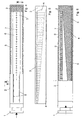
- the nozzle assembly shown in Figure 1 which is particularly suitable as a nozzle for electroplating plants with a horizontal passage of printed circuit boards, comprises a substantially cuboid housing 2. At one end face of the housing 2 is coupled to a liquid supply port of the housing connecting piece 1 for the supply of a Treatment liquid provided. At a side surface of the housing 2 to be arranged opposite the workpiece or the material to be treated, staggered rows of slots or rows are arranged which form outlet openings 8 for the treatment liquid. In the illustrated embodiments, all slot-like outlet openings or holes 8 have the same dimensions and therefore the same length and width or diameter. However, different dimensions may be selected to produce a predetermined spray or swirl image.
- a wedge-shaped insert 3 which is preferably made of plastic, and a U-shaped stiffener 4 for stabilizing this insert 3 is arranged, which consists of a, resistant to the chemicals used metal such.
- a, resistant to the chemicals used metal such as stainless steel, titanium, niobium or the like.
- the insert 3 serves to equalize the flow velocity in the liquid channel and thus to uniformly distribute the treatment liquid over the entire length of the nozzle arrangement.
- the insert 3 is tapered in the longitudinal direction so that it has the smallest thickness at its end arranged adjacent to the connecting piece 1 and the greatest thickness at its opposite end. Between the insert 3 and the stiffening 4 is a serving as a liquid channel 5 for the treatment liquid cavity. At the end coupled to the connecting piece 1, the flow cross-section of this liquid channel 5 is consequently the largest and continuously decreases towards the opposite end, where the flow cross-section is the smallest.
- the nozzle assembly has on the surface facing the material to be treated along its length preferably uniformly spaced outlet openings 8 in the form of through holes, which in the illustrated embodiment all have the same diameter. Instead of the illustrated holes and slot-shaped outlet openings can be used.
- the length of these outlet openings 8 is the same over the entire length of the nozzle arrangement.
- the treatment liquid is supplied to the nozzle arrangement in the direction of the arrow via the connecting piece 1 in the liquid channel 5 and forwarded in the longitudinal direction to the outlet openings 8.
- the wedge-shaped insert is arranged in the upper part of the nozzle arrangement.
- the outlet openings 8 are congruent in the housing 2 and in the insert 3. This results in differently long outlet channels with the same diameter of the outlet openings.
- the different lengths outlet channels can be used to further approximate the spray pattern. In the longer holes at a greater distance from the liquid inlet creates an increasing towards the end flow resistance, which ensures a further approximation of the flow conditions.
- an insert 3 or a recess and distributor openings 7 spaced apart from one another in the longitudinal direction of the insert 3 are formed in an insert 3.
- the milled or cutout on the insert 3 creates a storage space 6 for the treatment liquid between the distribution openings 7 of the insert 3 and the slit-like outlet openings 8 (not shown in FIG.
- the emerging from each manifold opening 7 liquid jet is first blasted against the upper housing wall, from there obliquely directed downwards against the wall insert 3 to emerge after a renewed change of direction through the slot-like outlet opening 8 to the material to be treated 10 out. This deflection reduces the dynamic force of the moving liquid targeted.
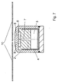
- FIG. 7 shows, as section C-C ', shown in FIG. 3, further details of the nozzle arrangement.
- the distributor openings 7 are of different lengths by the wedge-shaped insert 3. If this difference in length is disturbing, the bores for adjusting the flow conditions can be provided with countersinks 9 of different lengths according to section D (shown in FIG. 3).
- a combination of the progressively decreasing liquid passage 5 from the supply port to the opposite end of the nozzle assembly in conjunction with the storage space 6 and the multiple deflection of the liquid stream before exiting the discharge ports 8 ensures that the amount of exiting Liquid per slot and the exit velocity are the same.
- the stiffening 4 runs essentially over the entire length of the insert 3.
- the insert 3 is thickened by the wall thickness of the stiffening. This serves to seal off the liquid channel 5 inside the housing 2 of the nozzle arrangement (see also FIG. 3).
- Also along its upper side of the insert 3 is thickened in the same thickness, so that it sits securely on the U-shaped stiffener 4, as Figure 7 can be seen.
- the thickening of the insert 3 can be omitted.
- the stiffening can additionally by means of z. B. screws attached to the housing. However, the screws should not protrude into the liquid channel 5.
- a uniform flow velocity of the treatment liquid at the outlet openings 8 is realized in principle by two measures.
- the passage cross section for the treatment liquid in the interior of the nozzle arrangement that is to say in the liquid channel 5 continuously decreases from the connection piece 1 towards the end of the nozzle arrangement through the obliquely running insert 3.
- the distribution openings 7 do not direct the liquid jet directly to the item to be treated. Instead, it is deflected twice, only to emerge through the liquid outlet openings 8, in this example, rows of slots.
- the flow resistance in the distribution openings 7 increases due to their continuously increasing length constantly. So that this has no influence on the liquid distribution, the slope of the insert 3, in Figures 2, 3, and 5, preferably chosen somewhat shallower so that a gap remains at the end of the nozzle arrangement. In the example of FIG. 3, the gap height is approximately 4 mm at the end.
- the outlet openings 8 preferably have all the same widths or diameters, the same volume of liquid per unit of time also flows out at all outlet openings.
- FIG. 6 shows a further example of a nozzle arrangement with a storage space 6.
- the insert 3 is, as already described, wedge-shaped and installed in the lower part of the nozzle assembly.
- the insert 3 'in the upper part of the nozzle assembly has the same cross section over the entire length.
- distribution holes 7. They all have the same length. Accordingly, the wedge-shaped liquid channel extends sharpener at the end as shown in Figures 2, 3, and 5.
- the connecting piece 1 could be laid in the middle of the housing 2 of the nozzle arrangement, so that the supply of the treatment liquid takes place centrally.
- the passage cross-section of the liquid channel 5 in the interior of the housing 2 starting from the central connecting piece 1 to the two ends of the housing 2 would then, that is, on both sides, decrease and the thickness of the insert. 3 in accordance with starting from the central connecting piece 1 to the two ends widen, so that the length of the distributor bores 7 in the insert 3 increases on both sides.
- the continuously reducing passage cross-section of the liquid channel 5 is realized solely by the increasing width of the insert 3.
- a plurality of side surfaces of the liquid channel 5 are increasingly widened in the longitudinal direction of the housing 2.
- the storage space 6 can be dispensed with for further pressure distribution.
- the slot-like outlet openings 8 can also be provided with a different width, wherein the width, in particular in the longitudinal direction of the housing 2, can decrease starting from the inlet stub 1. As a rule, this leads to different volume flows, which can produce unequal results on the material to be treated.
- the distribution openings 7 can also be configured with different diameters, wherein for realizing a continuously increasing flow resistance, in particular a continuous reduction in the diameter of the distribution openings 7 is conceivable since the total pressure is highest at the end of the nozzle arrangement.
- counterbores 9 having a larger diameter (compare FIG. 3).
- these countersinks can be provided with a different depth, in particular with a depth that increases continuously in the longitudinal direction of the housing 2. It is also conceivable that the insert 3 and the housing 2 are designed in one piece.
- outlet openings 8 are provided, which in particular uniformly spaced and are arranged in two mutually offset rows of slots, but in principle a proper and satisfactory functionality the nozzle arrangement is also already ensured with only one, in particular, elongate outlet opening 8, for example, in the case of only one outlet opening 8 extending in slot-like fashion in the longitudinal direction of the housing 2.
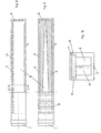
- FIG. 8-10 shows a further nozzle arrangement according to an exemplary embodiment of the present invention
- FIG. 8 a partial cross-sectional side view of the nozzle arrangement
- FIG. 9 a partial cross-sectional view of the nozzle arrangement
- FIG. 10 a cross-sectional view of the nozzle arrangement along a section line CC shown in FIG represents.
- the nozzle arrangement shown in FIGS. 8-10 is an exemplary embodiment which is particularly well suited for the uniform flooding of treatment baths with a treatment liquid.
- a treatment liquid such as oxygen from the air
- the nozzle arrangement illustrated in FIGS. 8-10 like the previously described embodiments, comprises a connecting piece 1 and an elongate, substantially parallelepipedic housing 2, in which an insert 3 is installed, which has a liquid channel 5 in the longitudinal direction of the nozzle arrangement or of the housing 2 defined decreasing cross section.
- the insert 3 reduces the cross-section of the liquid channel 5 on both sides, whereby the cross section of the liquid channel 5 is continuously and uniformly reduced from the connection piece 1 to the end of the nozzle arrangement, so that approximately the same flow rate of the treatment liquid is always present in the liquid channel 5 itself ,
- a cover or a lid 11 liquid-tight by a suitable joining technique, such as by welding or gluing, attached to the housing 2.
- the cover 11 has on its underside a multiplicity of slots or connecting channels running transversely to the longitudinal direction of the nozzle arrangement, which are in particular distributed uniformly over the entire length of action of the nozzle arrangement. These slots of the cover 11 together with the housing 2 liquid outlet openings 8 for the treatment liquid.
- the treatment liquid supplied via the connecting piece 1 of the nozzle arrangement can emerge from the liquid channel 5 via the slots formed in the cover 11 to the liquid outlet openings 8 provided on both sides of the nozzle arrangement or the housing 2.
- the description of the nozzle arrangement according to the invention relates in all embodiments to the conveying of the treatment liquid from the nozzle arrangement to the item to be treated.
- the nozzle arrangement works in the same way also for the extraction of the treatment liquid from the material to be treated into the nozzle arrangement. If degradation products are formed during the treatment or solids are removed, this form of electrolyte delivery is particularly advantageous. With the suction of the treatment liquid in the nozzle assembly the degradation products or solids are entrained and get on the fastest way to a regeneration unit or z. B. a filter that removes the solids. An impairment of the treatment result by these substances is thus almost impossible.
Claims (31)
- Ensemble à buses pour délivrer un liquide de traitement,
comportant un boîtier (2), allongé, qui présente au moins une ouverture d'arrivée de liquide, pour l'amenée du liquide de traitement, et au moins une ouverture de sortie de liquide (8) formée dans le boîtier (2), pour la délivrance du liquide de traitement,
un canal à liquide (5) étant aménagé dans le boîtier (2), pour amener le liquide de traitement de l'ouverture d'amenée de liquide à la au moins une ouverture de sortie de liquide (8), et
la section transversale du canal à liquide (5) diminuant dans la direction longitudinale du boîtier (2), en partant de l'ouverture d'arrivée de liquide,
caractérisé
en ce que le boîtier (2) est réalisé en matière plastique et, sur ou dans l'ensemble à buses, est présent au moins un élément de rigidification (4) en métal, s'étendant dans la direction longitudinale de l'ensemble à buses, et
en ce que dans l'ensemble à buses, est disposé un insert allongé (3, 3'), dans lequel sont formés plusieurs orifices répartiteurs (7) disposés à intervalle l'un de l'autre en direction longitudinale, de telle sorte que le canal à liquide (5) défini par l'insert (3, 3'), soit placé en liaison avec la au moins une ouverture de sortie de liquide (8), au travers des orifices répartiteurs (7), pour que le liquide de traitement soit amené à la au moins une ouverture de sortie de liquide (8) au travers des orifices répartiteurs (7), depuis le canal à liquide (5). - Ensemble à buses selon la revendication 1,
caractérisé
en ce que la section transversale du canal à liquide (5) diminue d'une façon continue dans la direction longitudinale du boîtier (2), en partant de l'ouverture d'arrivée de liquide. - Ensemble à buses selon la revendication 1 ou 2,
caractérisé
en ce que les orifices répartiteurs (7) de l'insert (3, 3') sont disposés de façon à être en coïncidence avec les ouvertures de sortie de liquide (8) dans le boîtier (2). - Ensemble à buses selon l'une des revendications précédentes,
caractérisé
en ce que la section transversale du canal à liquide (5) diminue de plusieurs côtés dans la direction longitudinale du boîtier (2), en partant de l'ouverture d'arrivée de liquide. - Ensemble à buses selon l'une des revendications précédentes,
caractérisé,
en ce que tous les orifices répartiteurs (7) présentent le même diamètre. - Ensemble à buses selon l'une des revendications précédentes,
caractérisé
en ce que la longueur des orifices répartiteurs (7) augmente dans la direction longitudinale du boîtier (2), en partant de l'ouverture d'arrivée de liquide. - Ensemble à buses selon l'une des revendications 1 à 5,
caractérisé
en ce que la longueur des orifices répartiteurs (7) de l'ouverture d'arrivée de liquide est identique dans la direction longitudinale du boîtier (2). - Ensemble à buses selon l'une des revendications 1 à 4,
caractérisé
en ce que les orifices répartiteurs (7) présentent un diamètre différent. - Ensemble à buses selon la revendication 8,
caractérisé
en ce que le diamètre des orifices répartiteurs (7) diminue dans la direction longitudinale du boîtier (2), en partant de l'ouverture d'arrivée de liquide. - Ensemble à buses selon l'une des revendications précédentes,
caractérisé
en ce que les orifices répartiteurs (7) sont, de leur côté tourné vers le canal à liquide (5), pourvus de fraisages (9). - Ensemble à buses selon la revendication 10,
caractérisé
en ce que les fraisages (9) des orifices répartiteurs (7) présentent une profondeur différente. - Ensemble à buses selon la revendication 11,
caractérisé
en ce que la profondeur des fraisages (9) des orifices répartiteurs (7) augmente dans la direction longitudinale du boîtier (2), en partant de l'ouverture d'arrivée de liquide. - Ensemble à buses selon l'une des revendications précédentes,
caractérisé
en ce que le boîtier (2) est doté d'une configuration sensiblement parallélépipédique et l'élément de rigidification (4) d'une configuration sensiblement en forme de u. - Ensemble à buses selon l'une des revendications précédentes,
caractérisé
en ce qu'entre la au moins une ouverture de sortie de liquide (8) et le canal à liquide (5) et immédiatement en amont de la au moins une ouverture de sortie de liquide (8), est aménagé un espace d'accumulation (6) pour la répartition de pression. - Ensemble à buses selon la revendication 14,
caractérisé
en ce que l'espace d'accumulation (6) est réalisé sous forme d'un évidement prévu dans l'insert allongé (3, 3'), du côté des orifices répartiteurs (7) tourné vers la au moins une ouverture de sortie de liquide (8). - Ensemble à buses selon la revendication 15,
caractérisé
en ce que tous les orifices répartiteurs (7) sont disposés sous un décalage dans l'espace qui, vis-à-vis de la au moins une ouverture de sortie de liquide (8), est tel que le liquide de traitement ne sorte des ouvertures de sortie de liquide (8), en passant par l'espace d'accumulation, qu'après avoir changé au moins deux fois de sens d'écoulement. - Ensemble à buses selon l'une des revendications précédentes,
caractérisé
en ce que la au moins une ouverture d'arrivée de liquide est prévue à une extrémité, dans la direction longitudinale, du boîtier (2). - Ensemble à buses selon l'une des revendications 1 à 16,
caractérisé
en ce que la au moins une ouverture d'arrivée de liquide est prévue au niveau d'un tronçon médian du boîtier (2). - Ensemble à buses selon l'une des revendications précédentes,
caractérisé
en ce que le boîtier (2) présente plusieurs ouvertures de sortie de liquide (8) placées à intervalle l'une de l'autre dans la direction longitudinale du boîtier (2). - Ensemble à buses selon la revendication 19,
caractérisé
en ce que les ouvertures de sortie de liquide (8) sont en forme de fente ou rondes. - Ensemble à buses selon la revendication 19 ou 20,
caractérisé
en ce que les ouvertures de sortie de liquide (8) présentent les mêmes dimensions. - Ensemble à buses selon la revendication 19 ou 20,
caractérisé
en ce que les ouvertures de sortie de liquide (8) possèdent une largeur diminuant sur la longueur du boîtier (2), en partant de l'ouverture d'arrivée de liquide, ou un diamètre diminuant sur la longueur du boîtier (2). - Ensemble à buses selon l'une des revendications 19 à 22,
caractérisé
en ce que les ouvertures de sortie de liquide (8), en forme de fente, sont formées en plusieurs rangées décalées l'une de l'autre, dans le boîtier (2). - Ensemble à buses selon l'une des revendications précédentes,
caractérisé
en ce que dans le boîtier (2), sont aménagés plusieurs canaux de jonction espacés l'un de l'autre dans la direction longitudinale du boîtier (2) et s'étendant dans le sens de la largeur du boîtier (2), lesquels canaux de jonction sont reliés, d'une part, au canal à liquide (5) ménagé dans le boîtier (2) et, d'autre part, à au moins une ouverture de sortie de liquide (8) respectivement. - Ensemble à buses selon la revendication 24,
caractérisé
en ce que les canaux de jonction sont aménagés dans un couvercle (11), qui est adapté sur le boîtier (2). - Ensemble à buses selon la revendication 25,
caractérisé
en ce que le couvercle (11) est adapté sur le boîtier (2) avec établissement d'une étanchéité aux liquides. - Ensemble à buses selon l'une des revendications 24 à 26,
caractérisé
en ce que les canaux de jonction sont disposés suivant un espacement mutuel uniforme dans la direction longitudinale du boîtier (2). - Ensemble à buses selon l'une des revendications 24 à 27,
caractérisé
en ce que les canaux de jonction sont répartis sensiblement sur la longueur entière du boîtier (2). - Ensemble à buses selon l'une des revendications 24 à 28,
caractérisé
en ce que chaque canal de jonction s'étend transversalement à la direction longitudinale du boîtier (2), sous une forme sensiblement rectiligne. - Ensemble à buses selon l'une des revendications 24 à 29,
caractérisé
en ce que, des deux côtés du boîtier (2), chaque canal de jonction débouche respectivement dans l'une des ouvertures de sortie de liquide (8). - Ensemble à buses selon l'une des revendications précédentes,
caractérisé
en ce qu'un insert allongé supplémentaire (3), qui est doté d'une forme conique dans sa direction longitudinale, est disposé dans le boîtier (2) et définit le canal à liquide (5) avec l'insert allongé (3') qui comporte les orifices répartiteurs (7).
Applications Claiming Priority (3)
| Application Number | Priority Date | Filing Date | Title |
|---|---|---|---|
| DE10255884 | 2002-11-29 | ||
| DE10255884A DE10255884B4 (de) | 2002-11-29 | 2002-11-29 | Düsenanordnung |
| PCT/EP2003/013421 WO2004050256A1 (fr) | 2002-11-29 | 2003-11-28 | Ensemble buse |
Publications (2)
| Publication Number | Publication Date |
|---|---|
| EP1565268A1 EP1565268A1 (fr) | 2005-08-24 |
| EP1565268B1 true EP1565268B1 (fr) | 2006-05-17 |
Family
ID=32335852
Family Applications (1)
| Application Number | Title | Priority Date | Filing Date |
|---|---|---|---|
| EP03785685A Expired - Lifetime EP1565268B1 (fr) | 2002-11-29 | 2003-11-28 | Ensemble buse |
Country Status (15)
| Country | Link |
|---|---|
| US (1) | US7650897B2 (fr) |
| EP (1) | EP1565268B1 (fr) |
| JP (1) | JP4331687B2 (fr) |
| KR (1) | KR100987400B1 (fr) |
| CN (1) | CN100352557C (fr) |
| AT (1) | ATE326283T1 (fr) |
| AU (1) | AU2003294745A1 (fr) |
| BR (1) | BR0316526A (fr) |
| DE (2) | DE10255884B4 (fr) |
| ES (1) | ES2263050T3 (fr) |
| HK (1) | HK1075857A1 (fr) |
| MY (1) | MY135613A (fr) |
| PL (1) | PL206436B1 (fr) |
| TW (1) | TWI276471B (fr) |
| WO (1) | WO2004050256A1 (fr) |
Families Citing this family (15)
| Publication number | Priority date | Publication date | Assignee | Title |
|---|---|---|---|---|
| DE102004002421A1 (de) * | 2004-01-16 | 2005-08-18 | Atotech Deutschland Gmbh | Düsenanordnung |
| GB2459055B (en) * | 2007-01-11 | 2012-05-23 | Peter Philip Andrew Lymn | Liquid treatment apparatus |
| EP2234732B1 (fr) * | 2007-12-17 | 2015-09-02 | Basf Se | Procédé et dispositif de fabrication d'éléments composites à partir de mousses à base d'isocyanate |
| IT1390869B1 (it) * | 2008-07-31 | 2011-10-19 | F M Srl | Unita' di erogazione di fluidi, in particolare smalti |
| CN101865483B (zh) * | 2009-04-20 | 2013-12-11 | 王秀全 | 吸油烟机的喷淋器和引流器 |
| CN102744224A (zh) * | 2012-07-12 | 2012-10-24 | 江苏尚能光伏精密设备有限公司 | 新型喷淋吹风装置 |
| KR101966768B1 (ko) * | 2012-11-08 | 2019-04-08 | 엘지디스플레이 주식회사 | 기판 세정장치 |
| EP2865502A1 (fr) * | 2013-10-25 | 2015-04-29 | Applied Materials Switzerland Sàrl | Scie à fil à semi-conducteurs comprenant une buse servant à produire un jet de fluide |
| US9966281B2 (en) | 2013-11-15 | 2018-05-08 | Taiwan Semiconductor Manufacturing Company, Ltd. | Methods and systems for chemical mechanical polish cleaning |
| AU2015328397B2 (en) * | 2014-10-09 | 2018-12-20 | Usnr, Llc | Self-cleaning jet tube |
| NL2013904B1 (en) * | 2014-12-02 | 2016-10-11 | Tempress Ip B V | Wafer boat and use thereof. |
| JP6385864B2 (ja) * | 2015-03-18 | 2018-09-05 | 株式会社東芝 | ノズルおよび液体供給装置 |
| GB2564893B (en) * | 2017-07-27 | 2020-12-16 | Semsysco Gmbh | Distribution system for chemical and/or electrolytic surface treatment |
| GB201713993D0 (en) * | 2017-08-31 | 2017-10-18 | Ge Healthcare Bio Sciences Ab | Air trapping device and nozzle therefore |
| US11524191B2 (en) * | 2020-09-25 | 2022-12-13 | Susan Voggenthaler | Helicopter drizzle pipe |
Family Cites Families (23)
| Publication number | Priority date | Publication date | Assignee | Title |
|---|---|---|---|---|
| US1971376A (en) * | 1932-10-29 | 1934-08-28 | United States Pipe Foundry | Apparatus for coating centrifugal pipe molds |
| US1971346A (en) * | 1932-11-08 | 1934-08-28 | Stockard R Hickey | Hydrostatic auxiliary starting means for torpedoes |
| US3212719A (en) * | 1963-11-20 | 1965-10-19 | Corpo Dino D Di | Water curtain protective spray nozzle adapter |
| US4132363A (en) | 1975-02-06 | 1979-01-02 | Eduard Kusters | Nozzle for producing a wide liquid jet |
| DE2504856B2 (de) * | 1975-02-06 | 1978-07-27 | Kuesters, Eduard, 4150 Krefeld | Spaltdüse zur Erzeugung eines breiten Flussigkeitsstrahls |
| GB2096490B (en) * | 1981-04-13 | 1984-12-05 | Davey Loewy Ltd | Spraying apparatus |
| US4550681A (en) * | 1982-10-07 | 1985-11-05 | Johannes Zimmer | Applicator for uniformly distributing a flowable material over a receiving surface |
| US4691722A (en) * | 1984-08-01 | 1987-09-08 | Fsi Corporation | Bowl for liquid spray processing machine |
| DE3528575A1 (de) * | 1985-08-06 | 1987-02-19 | Schering Ag | Verfahren und einrichtung zur reinigung, aktivierung und/oder metallisierung von bohrloechern in horizontal gefuehrten leiterplatten |
| GB8617100D0 (en) * | 1986-07-14 | 1986-08-20 | Albany Int Corp | Shower pipes |
| US4747541A (en) * | 1986-08-21 | 1988-05-31 | Morine Richard L | Dispensing apparatus |
| DE8703114U1 (fr) | 1987-02-25 | 1987-04-09 | Schering Ag, 1000 Berlin Und 4709 Bergkamen, De | |
| DE3708529A1 (de) * | 1987-03-16 | 1988-09-29 | Siemens Ag | Spuelmodul |
| DE3913132A1 (de) * | 1989-04-21 | 1990-12-20 | Hoechst Ag | Verfahren zum gleichmaessigen einleiten eines fluids und vorrichtung zur durchfuehrung des verfahrens |
| JPH0363142A (ja) * | 1989-08-01 | 1991-03-19 | Olympus Optical Co Ltd | イオン流記録ヘッド |
| JP3063142B2 (ja) | 1990-10-26 | 2000-07-12 | 三井サイテック株式会社 | 吸水性シート及びその製造方法 |
| US5334352A (en) * | 1992-09-23 | 1994-08-02 | Icn Biomedicals, Inc. | Manifold construction |
| DE4331496C2 (de) * | 1992-10-07 | 1998-03-19 | Monforts Gmbh & Co A | Ebenes Düsensystem |
| JP2912538B2 (ja) | 1993-12-08 | 1999-06-28 | 大日本スクリーン製造株式会社 | 浸漬型基板処理装置 |
| KR100195334B1 (ko) | 1996-08-16 | 1999-06-15 | 구본준 | 세정장치 |
| US6269823B1 (en) | 1998-05-04 | 2001-08-07 | Eagle-Picher Industries, Inc. | Can washing apparatus with plastic risers |
| TW391895B (en) * | 1998-10-02 | 2000-06-01 | Ultra Clean Technology Asia Pt | Method and apparatus for washing and drying semi-conductor devices |
| DE10044209A1 (de) * | 2000-09-07 | 2002-04-04 | Schmid Gmbh & Co Geb | Verfahren und Vorrichtung zur Behandlung von Gegenständen, besonders Leiterplatten |
-
2002
- 2002-11-29 DE DE10255884A patent/DE10255884B4/de not_active Expired - Fee Related
-
2003
- 2003-11-26 TW TW092133235A patent/TWI276471B/zh not_active IP Right Cessation
- 2003-11-28 AU AU2003294745A patent/AU2003294745A1/en not_active Abandoned
- 2003-11-28 CN CNB2003801028409A patent/CN100352557C/zh not_active Expired - Lifetime
- 2003-11-28 WO PCT/EP2003/013421 patent/WO2004050256A1/fr active IP Right Grant
- 2003-11-28 BR BR0316526-4A patent/BR0316526A/pt active Search and Examination
- 2003-11-28 MY MYPI20034561A patent/MY135613A/en unknown
- 2003-11-28 KR KR1020057007798A patent/KR100987400B1/ko active IP Right Grant
- 2003-11-28 EP EP03785685A patent/EP1565268B1/fr not_active Expired - Lifetime
- 2003-11-28 PL PL375201A patent/PL206436B1/pl unknown
- 2003-11-28 JP JP2004556217A patent/JP4331687B2/ja not_active Expired - Lifetime
- 2003-11-28 AT AT03785685T patent/ATE326283T1/de active
- 2003-11-28 ES ES03785685T patent/ES2263050T3/es not_active Expired - Lifetime
- 2003-11-28 US US10/536,624 patent/US7650897B2/en active Active
- 2003-11-28 DE DE50303397T patent/DE50303397D1/de not_active Expired - Lifetime
-
2005
- 2005-09-12 HK HK05107991A patent/HK1075857A1/xx not_active IP Right Cessation
Also Published As
| Publication number | Publication date |
|---|---|
| ATE326283T1 (de) | 2006-06-15 |
| TWI276471B (en) | 2007-03-21 |
| DE50303397D1 (de) | 2006-06-22 |
| EP1565268A1 (fr) | 2005-08-24 |
| DE10255884A1 (de) | 2004-06-24 |
| PL206436B1 (pl) | 2010-08-31 |
| ES2263050T3 (es) | 2006-12-01 |
| PL375201A1 (en) | 2005-11-28 |
| CN100352557C (zh) | 2007-12-05 |
| CN1711140A (zh) | 2005-12-21 |
| US20060102213A1 (en) | 2006-05-18 |
| HK1075857A1 (en) | 2005-12-30 |
| KR100987400B1 (ko) | 2010-10-13 |
| WO2004050256A1 (fr) | 2004-06-17 |
| JP2006507929A (ja) | 2006-03-09 |
| AU2003294745A1 (en) | 2004-06-23 |
| DE10255884B4 (de) | 2006-05-11 |
| BR0316526A (pt) | 2005-10-04 |
| US7650897B2 (en) | 2010-01-26 |
| JP4331687B2 (ja) | 2009-09-16 |
| MY135613A (en) | 2008-05-30 |
| TW200427516A (en) | 2004-12-16 |
| KR20050084634A (ko) | 2005-08-26 |
Similar Documents
| Publication | Publication Date | Title |
|---|---|---|
| EP1565268B1 (fr) | Ensemble buse | |
| EP0577681B1 (fr) | Tuyere a fente de distribution de liquides | |
| AT392807B (de) | Stoffauflauf fuer eine papiermaschine od.dgl. | |
| EP0436893B1 (fr) | Procédé et dispositif pour l'application uniforme d'un fluide sur un matériau en bande mouvant | |
| DE69729578T2 (de) | Flüssigkeitsabgabevorrichtung und -verfahren | |
| EP2323775B1 (fr) | Outil de revêtement pour le depot d'un film liquide sur un substrat | |
| EP1704759B1 (fr) | Dispositif injecteur et procede de traitement d'un produit au moyen d'un milieu de traitement | |
| EP1913165B1 (fr) | Dispositif pour refroidir une bande de metal | |
| EP0399325B1 (fr) | Disposition pour le traitement et/ou le nettoyage de matériau, notamment des cartes de circuits imprimés pourvues de forures | |
| EP0953205A1 (fr) | Dispositif de traitement de substrats | |
| EP2536268B1 (fr) | Dispositif de formage et de refroidissement pour une composition alimentaire fondue et coulante | |
| DE1511218C3 (de) | Papierbrei-Aufgabevorrichtung für Papiermaschinen | |
| WO2005105334A1 (fr) | Dispositif pour refroidir des toles et des feuillards | |
| DE19519211B4 (de) | Verfahren zur Behandlung von Gegenständen, insbesondere von Leiterplatten, sowie Vorrichtung zur Durchführung dieses Verfahrens | |
| DE102004018597B3 (de) | Applikationskopf zur Erzeugung einer Flüssigfolie | |
| EP0753357B1 (fr) | Dispositif d'application d'une couche mince de liquide, de manière uniforme sur la largeur, sur une bande | |
| DE19718769A1 (de) | Verfahren und Vorrichtung zur Behandlung, insbesondere zum Ätzen, von plattenförmigen Gegenständen, insbesondere von Leiterplatten | |
| DE4223542A1 (de) | Vorrichtung zur Behandlung von Leiterplatten mit einer Behandlungsflüssigkeit | |
| DE19823636B4 (de) | Düsenfeuchter | |
| DE102004001222B4 (de) | Düseneinheit und Gargerät mit einer Düseneinheit | |
| AT395183B (de) | Stoffauflauf fuer eine papiermaschine od. dgl. | |
| DE4430035A1 (de) | Vorrichtung zum Trocknen von Materialbahnen | |
| DD211371A1 (de) | Duesenanordnung zur beaufschlagung einer warenbahn mit einem gasfoermigen behandlungsmittel | |
| DE10331145A1 (de) | Vorrichtung zum direkten oder indirekten Auftragen von flüssigen bis pastösen Suspensionen auf Papier- oder Kartonbahnen | |
| DE102009030700A1 (de) | Reinigungs- und Bearbeitungsvorrichtung mit Absaugung |
Legal Events
| Date | Code | Title | Description |
|---|---|---|---|
| PUAI | Public reference made under article 153(3) epc to a published international application that has entered the european phase |
Free format text: ORIGINAL CODE: 0009012 |
|
| 17P | Request for examination filed |
Effective date: 20050427 |
|
| AK | Designated contracting states |
Kind code of ref document: A1 Designated state(s): AT BE BG CH CY CZ DE DK EE ES FI FR GB GR HU IE IT LI LU MC NL PT RO SE SI SK TR |
|
| AX | Request for extension of the european patent |
Extension state: AL LT LV MK |
|
| GRAP | Despatch of communication of intention to grant a patent |
Free format text: ORIGINAL CODE: EPIDOSNIGR1 |
|
| REG | Reference to a national code |
Ref country code: HK Ref legal event code: DE Ref document number: 1075857 Country of ref document: HK |
|
| DAX | Request for extension of the european patent (deleted) | ||
| GRAS | Grant fee paid |
Free format text: ORIGINAL CODE: EPIDOSNIGR3 |
|
| GRAA | (expected) grant |
Free format text: ORIGINAL CODE: 0009210 |
|
| AK | Designated contracting states |
Kind code of ref document: B1 Designated state(s): AT BE BG CH CY CZ DE DK EE ES FI FR GB GR HU IE IT LI LU MC NL PT RO SE SI SK TR |
|
| PG25 | Lapsed in a contracting state [announced via postgrant information from national office to epo] |
Ref country code: IT Free format text: LAPSE BECAUSE OF FAILURE TO SUBMIT A TRANSLATION OF THE DESCRIPTION OR TO PAY THE FEE WITHIN THE PRESCRIBED TIME-LIMIT;WARNING: LAPSES OF ITALIAN PATENTS WITH EFFECTIVE DATE BEFORE 2007 MAY HAVE OCCURRED AT ANY TIME BEFORE 2007. THE CORRECT EFFECTIVE DATE MAY BE DIFFERENT FROM THE ONE RECORDED. Effective date: 20060517 Ref country code: CZ Free format text: LAPSE BECAUSE OF FAILURE TO SUBMIT A TRANSLATION OF THE DESCRIPTION OR TO PAY THE FEE WITHIN THE PRESCRIBED TIME-LIMIT Effective date: 20060517 Ref country code: IE Free format text: LAPSE BECAUSE OF FAILURE TO SUBMIT A TRANSLATION OF THE DESCRIPTION OR TO PAY THE FEE WITHIN THE PRESCRIBED TIME-LIMIT Effective date: 20060517 Ref country code: SK Free format text: LAPSE BECAUSE OF FAILURE TO SUBMIT A TRANSLATION OF THE DESCRIPTION OR TO PAY THE FEE WITHIN THE PRESCRIBED TIME-LIMIT Effective date: 20060517 Ref country code: SI Free format text: LAPSE BECAUSE OF FAILURE TO SUBMIT A TRANSLATION OF THE DESCRIPTION OR TO PAY THE FEE WITHIN THE PRESCRIBED TIME-LIMIT Effective date: 20060517 Ref country code: RO Free format text: LAPSE BECAUSE OF FAILURE TO SUBMIT A TRANSLATION OF THE DESCRIPTION OR TO PAY THE FEE WITHIN THE PRESCRIBED TIME-LIMIT Effective date: 20060517 |
|
| REG | Reference to a national code |
Ref country code: GB Ref legal event code: FG4D Free format text: NOT ENGLISH |
|
| REG | Reference to a national code |
Ref country code: CH Ref legal event code: EP |
|
| GBT | Gb: translation of ep patent filed (gb section 77(6)(a)/1977) |
Effective date: 20060517 |
|
| REG | Reference to a national code |
Ref country code: IE Ref legal event code: FG4D Free format text: LANGUAGE OF EP DOCUMENT: GERMAN |
|
| REF | Corresponds to: |
Ref document number: 50303397 Country of ref document: DE Date of ref document: 20060622 Kind code of ref document: P |
|
| REG | Reference to a national code |
Ref country code: HK Ref legal event code: GR Ref document number: 1075857 Country of ref document: HK |
|
| PG25 | Lapsed in a contracting state [announced via postgrant information from national office to epo] |
Ref country code: DK Free format text: LAPSE BECAUSE OF FAILURE TO SUBMIT A TRANSLATION OF THE DESCRIPTION OR TO PAY THE FEE WITHIN THE PRESCRIBED TIME-LIMIT Effective date: 20060817 Ref country code: SE Free format text: LAPSE BECAUSE OF FAILURE TO SUBMIT A TRANSLATION OF THE DESCRIPTION OR TO PAY THE FEE WITHIN THE PRESCRIBED TIME-LIMIT Effective date: 20060817 |
|
| PG25 | Lapsed in a contracting state [announced via postgrant information from national office to epo] |
Ref country code: PT Free format text: LAPSE BECAUSE OF FAILURE TO SUBMIT A TRANSLATION OF THE DESCRIPTION OR TO PAY THE FEE WITHIN THE PRESCRIBED TIME-LIMIT Effective date: 20061017 |
|
| PG25 | Lapsed in a contracting state [announced via postgrant information from national office to epo] |
Ref country code: MC Free format text: LAPSE BECAUSE OF NON-PAYMENT OF DUE FEES Effective date: 20061130 Ref country code: BE Free format text: LAPSE BECAUSE OF NON-PAYMENT OF DUE FEES Effective date: 20061130 |
|
| REG | Reference to a national code |
Ref country code: ES Ref legal event code: FG2A Ref document number: 2263050 Country of ref document: ES Kind code of ref document: T3 |
|
| ET | Fr: translation filed | ||
| REG | Reference to a national code |
Ref country code: IE Ref legal event code: FD4D |
|
| PLBE | No opposition filed within time limit |
Free format text: ORIGINAL CODE: 0009261 |
|
| STAA | Information on the status of an ep patent application or granted ep patent |
Free format text: STATUS: NO OPPOSITION FILED WITHIN TIME LIMIT |
|
| 26N | No opposition filed |
Effective date: 20070220 |
|
| BERE | Be: lapsed |
Owner name: ATOTECH DEUTSCHLAND G.M.B.H. Effective date: 20061130 |
|
| PG25 | Lapsed in a contracting state [announced via postgrant information from national office to epo] |
Ref country code: GR Free format text: LAPSE BECAUSE OF FAILURE TO SUBMIT A TRANSLATION OF THE DESCRIPTION OR TO PAY THE FEE WITHIN THE PRESCRIBED TIME-LIMIT Effective date: 20060818 |
|
| PG25 | Lapsed in a contracting state [announced via postgrant information from national office to epo] |
Ref country code: EE Free format text: LAPSE BECAUSE OF FAILURE TO SUBMIT A TRANSLATION OF THE DESCRIPTION OR TO PAY THE FEE WITHIN THE PRESCRIBED TIME-LIMIT Effective date: 20060517 Ref country code: BG Free format text: LAPSE BECAUSE OF FAILURE TO SUBMIT A TRANSLATION OF THE DESCRIPTION OR TO PAY THE FEE WITHIN THE PRESCRIBED TIME-LIMIT Effective date: 20060817 |
|
| PG25 | Lapsed in a contracting state [announced via postgrant information from national office to epo] |
Ref country code: CH Free format text: LAPSE BECAUSE OF NON-PAYMENT OF DUE FEES Effective date: 20071130 Ref country code: HU Free format text: LAPSE BECAUSE OF FAILURE TO SUBMIT A TRANSLATION OF THE DESCRIPTION OR TO PAY THE FEE WITHIN THE PRESCRIBED TIME-LIMIT Effective date: 20061118 Ref country code: LI Free format text: LAPSE BECAUSE OF NON-PAYMENT OF DUE FEES Effective date: 20071130 Ref country code: LU Free format text: LAPSE BECAUSE OF NON-PAYMENT OF DUE FEES Effective date: 20061128 Ref country code: TR Free format text: LAPSE BECAUSE OF FAILURE TO SUBMIT A TRANSLATION OF THE DESCRIPTION OR TO PAY THE FEE WITHIN THE PRESCRIBED TIME-LIMIT Effective date: 20060517 |
|
| REG | Reference to a national code |
Ref country code: CH Ref legal event code: PL |
|
| PG25 | Lapsed in a contracting state [announced via postgrant information from national office to epo] |
Ref country code: CY Free format text: LAPSE BECAUSE OF FAILURE TO SUBMIT A TRANSLATION OF THE DESCRIPTION OR TO PAY THE FEE WITHIN THE PRESCRIBED TIME-LIMIT Effective date: 20060517 |
|
| PGFP | Annual fee paid to national office [announced via postgrant information from national office to epo] |
Ref country code: ES Payment date: 20091123 Year of fee payment: 7 Ref country code: FI Payment date: 20091113 Year of fee payment: 7 |
|
| PGFP | Annual fee paid to national office [announced via postgrant information from national office to epo] |
Ref country code: NL Payment date: 20091112 Year of fee payment: 7 |
|
| PGFP | Annual fee paid to national office [announced via postgrant information from national office to epo] |
Ref country code: FR Payment date: 20091201 Year of fee payment: 7 Ref country code: GB Payment date: 20091119 Year of fee payment: 7 Ref country code: IT Payment date: 20091121 Year of fee payment: 7 |
|
| REG | Reference to a national code |
Ref country code: NL Ref legal event code: V1 Effective date: 20110601 |
|
| GBPC | Gb: european patent ceased through non-payment of renewal fee |
Effective date: 20101128 |
|
| REG | Reference to a national code |
Ref country code: FR Ref legal event code: ST Effective date: 20110801 |
|
| PG25 | Lapsed in a contracting state [announced via postgrant information from national office to epo] |
Ref country code: NL Free format text: LAPSE BECAUSE OF NON-PAYMENT OF DUE FEES Effective date: 20110601 Ref country code: FI Free format text: LAPSE BECAUSE OF NON-PAYMENT OF DUE FEES Effective date: 20101128 |
|
| PG25 | Lapsed in a contracting state [announced via postgrant information from national office to epo] |
Ref country code: FR Free format text: LAPSE BECAUSE OF NON-PAYMENT OF DUE FEES Effective date: 20101130 |
|
| PG25 | Lapsed in a contracting state [announced via postgrant information from national office to epo] |
Ref country code: GB Free format text: LAPSE BECAUSE OF NON-PAYMENT OF DUE FEES Effective date: 20101128 |
|
| PG25 | Lapsed in a contracting state [announced via postgrant information from national office to epo] |
Ref country code: IT Free format text: LAPSE BECAUSE OF NON-PAYMENT OF DUE FEES Effective date: 20101128 |
|
| REG | Reference to a national code |
Ref country code: ES Ref legal event code: FD2A Effective date: 20120110 |
|
| PG25 | Lapsed in a contracting state [announced via postgrant information from national office to epo] |
Ref country code: ES Free format text: LAPSE BECAUSE OF NON-PAYMENT OF DUE FEES Effective date: 20101129 |
|
| PGFP | Annual fee paid to national office [announced via postgrant information from national office to epo] |
Ref country code: DE Payment date: 20221123 Year of fee payment: 20 Ref country code: AT Payment date: 20221121 Year of fee payment: 20 |
|
| REG | Reference to a national code |
Ref country code: DE Ref legal event code: R071 Ref document number: 50303397 Country of ref document: DE |
|
| REG | Reference to a national code |
Ref country code: AT Ref legal event code: MK07 Ref document number: 326283 Country of ref document: AT Kind code of ref document: T Effective date: 20231128 |