EP1565001A1 - Codierungs-/decodierungsverfahren für bewegliche bilder und einrichtung - Google Patents
Codierungs-/decodierungsverfahren für bewegliche bilder und einrichtung Download PDFInfo
- Publication number
- EP1565001A1 EP1565001A1 EP03772862A EP03772862A EP1565001A1 EP 1565001 A1 EP1565001 A1 EP 1565001A1 EP 03772862 A EP03772862 A EP 03772862A EP 03772862 A EP03772862 A EP 03772862A EP 1565001 A1 EP1565001 A1 EP 1565001A1
- Authority
- EP
- European Patent Office
- Prior art keywords
- predictive
- image
- signal
- generating
- image signal
- Prior art date
- Legal status (The legal status is an assumption and is not a legal conclusion. Google has not performed a legal analysis and makes no representation as to the accuracy of the status listed.)
- Withdrawn
Links
- 238000000034 method Methods 0.000 title claims description 63
- 239000013598 vector Substances 0.000 claims abstract description 39
- 230000002457 bidirectional effect Effects 0.000 claims description 7
- 230000001447 compensatory effect Effects 0.000 claims description 3
- 230000015654 memory Effects 0.000 abstract description 27
- 230000009466 transformation Effects 0.000 abstract description 6
- 230000006870 function Effects 0.000 description 22
- 238000005562 fading Methods 0.000 description 13
- 238000010586 diagram Methods 0.000 description 12
- 230000008859 change Effects 0.000 description 11
- 230000008569 process Effects 0.000 description 10
- 238000011156 evaluation Methods 0.000 description 9
- 239000000872 buffer Substances 0.000 description 7
- 230000006872 improvement Effects 0.000 description 7
- 230000007274 generation of a signal involved in cell-cell signaling Effects 0.000 description 4
- 238000012935 Averaging Methods 0.000 description 3
- 230000005540 biological transmission Effects 0.000 description 3
- 230000008901 benefit Effects 0.000 description 2
- 230000003139 buffering effect Effects 0.000 description 2
- 230000003247 decreasing effect Effects 0.000 description 2
- 238000013213 extrapolation Methods 0.000 description 2
- FVTCRASFADXXNN-SCRDCRAPSA-N flavin mononucleotide Chemical compound OP(=O)(O)OC[C@@H](O)[C@@H](O)[C@@H](O)CN1C=2C=C(C)C(C)=CC=2N=C2C1=NC(=O)NC2=O FVTCRASFADXXNN-SCRDCRAPSA-N 0.000 description 2
- 238000013139 quantization Methods 0.000 description 2
- 240000008168 Ficus benjamina Species 0.000 description 1
- 230000010485 coping Effects 0.000 description 1
- 230000002123 temporal effect Effects 0.000 description 1
Images


Classifications
-
- H—ELECTRICITY
- H04—ELECTRIC COMMUNICATION TECHNIQUE
- H04N—PICTORIAL COMMUNICATION, e.g. TELEVISION
- H04N19/00—Methods or arrangements for coding, decoding, compressing or decompressing digital video signals
- H04N19/50—Methods or arrangements for coding, decoding, compressing or decompressing digital video signals using predictive coding
- H04N19/503—Methods or arrangements for coding, decoding, compressing or decompressing digital video signals using predictive coding involving temporal prediction
- H04N19/51—Motion estimation or motion compensation
-
- H—ELECTRICITY
- H04—ELECTRIC COMMUNICATION TECHNIQUE
- H04N—PICTORIAL COMMUNICATION, e.g. TELEVISION
- H04N19/00—Methods or arrangements for coding, decoding, compressing or decompressing digital video signals
- H04N19/10—Methods or arrangements for coding, decoding, compressing or decompressing digital video signals using adaptive coding
- H04N19/102—Methods or arrangements for coding, decoding, compressing or decompressing digital video signals using adaptive coding characterised by the element, parameter or selection affected or controlled by the adaptive coding
- H04N19/103—Selection of coding mode or of prediction mode
- H04N19/105—Selection of the reference unit for prediction within a chosen coding or prediction mode, e.g. adaptive choice of position and number of pixels used for prediction
-
- H—ELECTRICITY
- H04—ELECTRIC COMMUNICATION TECHNIQUE
- H04N—PICTORIAL COMMUNICATION, e.g. TELEVISION
- H04N19/00—Methods or arrangements for coding, decoding, compressing or decompressing digital video signals
- H04N19/10—Methods or arrangements for coding, decoding, compressing or decompressing digital video signals using adaptive coding
- H04N19/102—Methods or arrangements for coding, decoding, compressing or decompressing digital video signals using adaptive coding characterised by the element, parameter or selection affected or controlled by the adaptive coding
- H04N19/103—Selection of coding mode or of prediction mode
- H04N19/107—Selection of coding mode or of prediction mode between spatial and temporal predictive coding, e.g. picture refresh
-
- H—ELECTRICITY
- H04—ELECTRIC COMMUNICATION TECHNIQUE
- H04N—PICTORIAL COMMUNICATION, e.g. TELEVISION
- H04N19/00—Methods or arrangements for coding, decoding, compressing or decompressing digital video signals
- H04N19/10—Methods or arrangements for coding, decoding, compressing or decompressing digital video signals using adaptive coding
- H04N19/134—Methods or arrangements for coding, decoding, compressing or decompressing digital video signals using adaptive coding characterised by the element, parameter or criterion affecting or controlling the adaptive coding
-
- H—ELECTRICITY
- H04—ELECTRIC COMMUNICATION TECHNIQUE
- H04N—PICTORIAL COMMUNICATION, e.g. TELEVISION
- H04N19/00—Methods or arrangements for coding, decoding, compressing or decompressing digital video signals
- H04N19/46—Embedding additional information in the video signal during the compression process
-
- H—ELECTRICITY
- H04—ELECTRIC COMMUNICATION TECHNIQUE
- H04N—PICTORIAL COMMUNICATION, e.g. TELEVISION
- H04N19/00—Methods or arrangements for coding, decoding, compressing or decompressing digital video signals
- H04N19/50—Methods or arrangements for coding, decoding, compressing or decompressing digital video signals using predictive coding
- H04N19/503—Methods or arrangements for coding, decoding, compressing or decompressing digital video signals using predictive coding involving temporal prediction
- H04N19/51—Motion estimation or motion compensation
- H04N19/573—Motion compensation with multiple frame prediction using two or more reference frames in a given prediction direction
-
- H—ELECTRICITY
- H04—ELECTRIC COMMUNICATION TECHNIQUE
- H04N—PICTORIAL COMMUNICATION, e.g. TELEVISION
- H04N19/00—Methods or arrangements for coding, decoding, compressing or decompressing digital video signals
- H04N19/60—Methods or arrangements for coding, decoding, compressing or decompressing digital video signals using transform coding
- H04N19/61—Methods or arrangements for coding, decoding, compressing or decompressing digital video signals using transform coding in combination with predictive coding
Definitions
- the invention relates to a method of encoding /decoding effectively a fading image and a dissolve image and an apparatus therefor.
- a motion compensated predictive interframe encoding is used as one of encoding modes.
- a predictive model in the motion compensated predictive interframe encoding is adopted a model indicating the most high predictive efficiency when luminosity does not vary in a time axis.
- the fading image that luminosity of the image varies, for example, in the case of fading-in from a black image to a normal image, a method of performing a prediction adequately according to a change of luminosity of the image is not known. Consequently, there is a problem to need the large number of encoded bits for the purpose of maintaining an image quality in a fading image.
- Patent No. 3166716 discloses a technique of coping with the problem by detecting a fading image area and changing an allocation of the number of encoded bits thereto.
- the large number of encoded bits are allocated to an beginning part of the fade-out that brightness varies.
- the last part of the fade-out usually reduces allocation of the number of encoded bits since it normally becomes a monochrome image resulting in making the encoding easy. With such a way, a total image quality is improved without increasing the total number of encoded bits.
- Patent No. 2938412 discloses an encoding system that deals with the above problem in a fading image by compensating for a reference image according to two parameters of an amount of luminance change and an amount of contrast change.
- Patent No. 3166716 improves an image quality without increasing the total number of encoded bits in encoding a fading image by detecting a fading image area, and changing an allocation of the number of encoded bits. For this reason, there is the advantage that the encoding can be realized within the framewark of an existing encoding system. However, since the prediction efficiency is not essentially improved, a notable improvement of the encoding efficiency cannot be expected.
- Patent 2938412 has a merit that the predictive efficiency on a fading image improves.
- the predictive efficiency to be enough for so-called a dissolve image referred to as a cross fade image
- a cross fade image which an image gradually varies from an image to another image cannot be obtained.
- the system of Thomas Wiegand and Berand Girod cannot sufficiently deal with a fading image and a dissolve image, and cannot improve a predictive efficiency even if a plurality of reference frames are prepared.
- An object of the present invention is to provide a video-encoding method, a video-decoding method, and an apparatus therefor that make it possible to encode in high efficiency a video image whose luminance varies with time such as a fading image and a dissolve image and decrease a computation amount.
- a first predictive image signal generation method of generating a predictive image signal according to a reference image number and a predictive parameter of a combination selected for each to-be-encoded region of the input video signal, from a plurality of combinations of at least one reference image number with predictive parameters.
- a second predictive signal generation method of generating a predictive image signal according to a predictive parameter computed every to-be-encoded region based on the reference image numbers of the plurality of reference images and an image-to-image distance of the plurality of reference images.
- a predictive error signal expressing an error of a predictive image signal generated in this way with respect to an input video signal is generated, and index information indicating either of a set of the predictive error signal and motion vector information and a set of a selected combination and the reference image numbers of a plurality of reference images is encoded.
- a predictive type of a to-be-encoded region of an input video signal is a first predictive type to use a reference image for a motion compensated predictive encoding
- a first prediction signal generation method is used.
- a predictive type of a to-be-encoded region is a bidirectional predictive type and the number of reference images used for a motion compensated predictive encoding is plural
- a second predictive signal generation method is used.
- coded data including a predictive error signal representing an error of a predictive image signal with respect to a video signal, motion vector information, and index information indicating either of a combination of the reference image number and a predictive parameter and the reference image numbers of a plurality of reference images are decoded.
- the decoded index information represents the combination
- a predictive image signal is generated according to the reference image number and predictive parameter of the combination.
- the decoded index information represents the reference image number of a plurality of reference images
- a predictive image signal is generated according to the reference image number and a predictive parameter computed based on an image-to-image distance of the plurality of reference images.
- a playback video signal is generated using the predictive error signal and predictive image signal generated in this way.
- a first predictive image generation method of generating a predictive image signal according to a combination of the reference image number and a predictive parameter, and a second predictive image generation method of generating a predictive image signal using a predictive parameter calculated based on a frame-to-frame distance of selected plurality of reference images are prepared, and either thereof is selected according to the number of reference images and a predictive type that are used for a motion compensated predictive encoding.
- an appropriate predictive image signal can be generated by a predictive system with a higher predictive efficiency for an input video signal from which a predictive image signal cannot be appropriately generated by a predictive system of a normal video encoding, for example, a fading image and a dissolve image, too.
- information concerning a reference image number and a predictive parameter is not sent from the encoding side to the decoding side, but index information indicating combination of a reference image number with a predictive parameter, or index information indicating combination of predictive parameters is sent in the case of sending the reference image number separately.
- index information indicating combination of a reference image number with a predictive parameter, or index information indicating combination of predictive parameters is sent in the case of sending the reference image number separately.
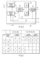
- FIG. 1 shows configuration of a video encoding apparatus related to the first embodiment of the present invention.
- a video signal 100 in units of a frame, for example, in this example.
- This video signal 100 is input to a subtracter 101 to generate a predictive error signal by obtaining a difference with respect to a predictive image signal 212.
- Either of the predictive error signal and input video signal 100 is selected with a mode selection switch 102, and subjected to an orthogonal transformation, for example, discrete cosine transform (DCT) with an orthogonal transformer 103.
- the orthogonal transformer 103 generates orthogonal transformed coefficient information, for example, DCT coefficient information.
- the orthogonal transformed coefficient information is quantized with a quantizer 104, and then quantized orthogonal transformed coefficient information 210 is led to a variable length encoder 111.
- the quantized orthogonal transformed coefficient information 210 is input to a local decoder.
- the quantized orthogonal transformed coefficient information 210 is subjected to a process to be inversive to that of the quantizer 104 and orthogonal transformer 103 with a dequantizer 105 and an inverse orthogonal transformer 106, to reconstruct a signal similar to the predictive error signal.
- the reconstructed signal is added to a predictive image signal 212 input through a switch 109 with an adder 107 to generate a local decoded image signal 211.
- the local decoded image signal 211 is input to a frame memory / predictive image generator 108.
- the frame memory / predictive image generator 108 selects one combination from a plurality of combinations of a reference frame number and a predictive parameter that are prepared beforehand.
- the image signal (local decoded image signal 211) of the reference frame indicated by the reference frame number of the selected combination is subjected to computation for a linear sum according to a predictive parameter in the selected combination. Further, in this example, a reference image signal of a frame unit is generated by adding an offset to the linear sum according to the predictive parameter. Thereafter, the frame memory / predictive image generator 108 subjects the reference image signal to motion compensation using a motion vector to generate a predictive image signal 212.
- the frame memory / predictive image generator 108 generates motion vector information 214 and index information 215 indicating selected combination of the reference frame number and predictive parameter, and further sends information to be necessary for selection of an encoding mode to the mode selector 212.
- the motion vector information 214 and index information 215 are input to the variable length encoder 111.
- the frame memory / predictive image generator 108 will be described in detail later.
- a mode selector 110 selects an encoding mode in units of a macroblock based on the predictive information P from the frame memory / predictive image generator 108, that is, selects either of an intraframe encoding and a motion compensated predictive interframe encoding to output switch control signals M and S.
- switches 102 and 112 are switched to A side by the switch control signals M and S, whereby the input video signal 100 is input to the orthogonal transformer 103.
- the switches 102 and 112 are switched to a B side by the switch control signals M and S, so that the predictive error signal from the subtracter 102 is input to the orthogonal transformer 103, and the predictive image signal 212 from the frame memory / predictive image generator 108 is input to the adder 107.
- the mode information 213 is output from the mode selector 212 and input to the variable length encoder 111.
- variable length encoder 111 the orthogonal transformed coefficient information 210, mode information 213, motion vector information 214 and index information 215 are subjected to a variable length encoding. Each variable-length code generated in this way is multiplied and then filtered by the output buffer 115. Thus, the encoded data 116 output from the output buffer 115 is sent to the transmission system or a storage system not shown.
- the encoding controller 113 monitors control of the encoder 112, concretely, for example, a buffering volume of the output buffer 115, and controls an encoding parameter such as quantization step size of the quantizer 104 for the purpose of making the buffering volume constant.
- FIG. 2 shows detailed configuration of the frame memory / predictive image generator 108 in FIG. 1.
- the local decoded image signal 211 input from the adder 107 in FIG. 1 is stored in the frame memory set 202 under control of the memory controller 201.
- the frame memory set 202 comprises a plurality of (N) frame memories FM1 to FMN for temporally storing the local decoded image signal 211 as a reference frame.
- the predictive parameter controller 203 prepares a plurality of combinations of a reference frame number and a predictive parameter as a table beforehand.
- the predictive parametric controller 203 selects a combination of a reference frame number of the reference frame used for generating a predictive image signal 212 based on the input video signal 100 and a predictive parameter, and outputs index information 215 indicating the selected combination.
- a plurality of frame motion evaluators 204 each generates a reference image signal according to the combination of the reference frame number and index information, which is selected with the predictive parameter controller 203.
- the plurality of frame motion evaluators 204 evaluates an amount of motion and a predictive error from this reference image signal and the input image signal 100, and outputs motion vector information 214 which makes a prediction error minimum.
- a plurality of frame motion compensators 205 generate the predictive image signal 212 by subjecting the reference image signal selected with the plurality of frame motion evaluator 204 every block to motion compensation according to the motion vector.
- the following equations (1), (2) and (3) each show an example of a predictive equation using a reference image number and a predictive parameter which are prepared with the predictive parameter controller 203.
- An example as shown in here shows predictive equations applied to a case that a to-be-encoded image as referred to as so-called P picture is subjected to a motion compensated prediction using a single reference image (reference picture) to generate a predictive image signal, and a case that a to-be-encoded image as referred to as so-called B picture is subjected to a motion compensated prediction using only one of two reference images to generate a predictive image signal.
- Y clip (( D 1 ( i ) ⁇ R Y ( i ) + 2 L Y - 1 ) >> L Y + D 2 ( i ))
- Cb clip (( E 1 ( i ) ⁇ (R Cb ( i ) - 128 ) + 2 L C -1 ) >> L C + E 2 ( i ) + 128)
- Cr clip (( F ( i ) 1 ⁇ ( R Cr ( i ) - 128) + 2 L C -1 ) >> L C + F 2 ( i ) + 128)
- Y indicates a predictive image signal of a luminance signal
- Cb and Cr indicate predictive image signals of two color-difference signals
- RY(i), RCb(i) and RCr(i) indicate luminance signal and pixel values of two color-difference signals of the reference image signal of index i.
- D1(i) and D2(i) indicate a predictive coefficient of the luminance signal of the index i, and an offset, respectively.
- E1(i) and E2(i) indicate a predictive coefficient of the color-difference signal Cb of the index i and offsets respectively.
- F1(i) and F2(i) indicate a predictive coefficient of the color-difference signal Cr of the index i, and an offset respectively.
- the index i indicates a value from zero to (the maximum number of reference images -1) and is encoded every to-be-encoded block (for example, every macroblock) and transmitted by the video decoding apparatus.
- Prediction parameters D1(i), D2(i), E1(i), E2(i), F1(i), and F2(i) are values determined between the video encoding apparatus and the decoding apparatus beforehand, or predetermined encoding units such as a frame, a field or a slice, and shared with both apparatuses by being encoded along with encoded data and transmitted from the video encoding apparatus to the decoding apparatus.
- the equations (1), (2) and (3) are predictive equations making it possible to avoid a division process by choosing denominator of the predictive coefficient multiplied by the reference image signal like two exponentiation, namely, 2, 4, 8, 16, ..., and compute by an arithmetic shift. By this, it is possible to avoid increase of a computation cost by the division process.
- Function clip( ) is a clipping function which is set to 0 when the value within ( ) is smaller than 0, and to 255 when it is larger than 255, and the integer of 255 is returned from 0.
- LY is a shift amount of a luminance signal
- LC is a shift amount of a color-difference signal.
- These shift amounts LY and LC use values determined with a video encoding apparatus and a decoding apparatus beforehand. Alternatively, they are shared with both apparatuses by being encoded along with a table and coded data in an encoding unit such as a frame, a field or a slice, which is predetermined in a video encoding apparatus, and transmitted to the video decoding apparatus.
- a combination table of a reference image number and a predictive parameter which is shown in FIG. 3 is prepared in the predictive parameter controller 203 in FIG. 2.
- This table is used when the number of reference image is 1.
- the index i corresponds to the predictive image which can be selected every block.
- the reference image number is, in other words, the number of a local decoded image used as a reference image.
- the table shown in FIG. 3 includes predictive parameters D1(i), D2(i), E1(i), E2(i), F1(i), and F2(i) that are assigned to a luminance signal and two color-difference signals in correspondence with equations (1), (2) and (3).
- Flag is a flag indicating whether the predictive equation using the predictive parameters is applied to the reference image number designated by the index i.
- Flag is "0"
- the motion compensated prediction is performed using the local decoded image of the reference image number designated by the index i without using the predictive parameter.
- the motion compensated prediction is done by generating a predictive image according to the equations (1), (2) and (3), using the predictive parameter and the local decoded image of the reference image number designated by the index i.
- the Flag information uses values determined with a video encoding apparatus and a decoding apparatus beforehand. Alternatively, it is shared with both apparatuses by being encoded along with a table and coded data in an encoding unit such as a frame, a field or a slice, which is predetermined in a video encoding apparatus, and transmitted to the video decoding apparatus.
- Equation (4), (5) and (6) show an example of predictive equations for a reference image number and a predictive parameter prepared with the predictive parameter controller 203 when a predictive image signal is generated using two reference images.
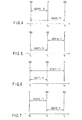
- FIGS. 4 to 7 a temporal position relation between a to-be-encoded image to be encoded currently and two reference images is expressed as shown in FIGS. 4 to 7 using the indexes i and j.
- FIG. 4 shows an example that the to-be-encoded image n is interpolated between the reference image designated by the index i and the reference image designated by the index j.
- Tn, Ti and Tj express positions of the to-be-encoded image, the reference image designated by the index i, and the reference image designated by the index j, respectively.
- the value increases toward the right. Consequently, the relation of Ti ⁇ Tn ⁇ Tj is established.
- FIG. 5 shows an example wherein the reference image designated by the index i and the reference image designated by the index j both are in a past position in terms of time than the to-be-encoded image n.
- FIG. 6 shows another example wherein the reference image designated by the index i and the reference image designated by the index j both are in a past position in terms of time than the to-be-encoded image n.
- FIG. 7 shows an example wherein the reference image designated by the index i and the reference image designated by the index j both are in a future position in terms of time than the to-be-encoded image n.
- L is a shift amount in the equations (4) to (8).
- the shift amount uses a value determined between the video encoding apparatus and the decoding apparatus beforehand, or is transmitted from the video encoding apparatus to the decoding apparatus with being encoded along with encoded data in a predetermined encoding unit such as a frame, a field or a slice, and shared with both apparatuses.
- the function of clip2 in the equations (6) and (8) is a function for returning an integer with limiting the maximum value and the minimum value of the weighting factors obtained by computation using a value (referred to as a value simply) within ( ) of clip2( ), that is, an image-to-image distance.
- a value simply within ( ) of clip2( )
- a first configuration of the function clip2 is a clipping function that makes -2 M , when the value is smaller than -2 M , and (2 M -1), when it is larger than (2 M -1).
- the integer not less than -2 M and not more than (2 M -1) is returned.
- the pixel is 8 bits, 9 bits are necessary for expression of the value of (R (j) -R (i)), and (M+10) bits are necessary for expression of the predictive coefficient W. Therefore, it is possible to compute a predictive image value with an operation precision of (M+10) bits.
- M assumes a non-negative integer not less than L.
- a second configuration of the function clip2 assumes a function having a rule that it is set at 2 L-1 when the value is smaller than -2 M , and at 2 L-1 when the value is larger than (2 M- 1), and returning an integer not less than -2 M and not more than (2 M- 1).
- a third configuration of the function clip2 is a clipping function setting at 1 when the value is smaller than 1, and 2 M when the value is larger than 2 M , and a function returning an integer not less than 1 and not more than 2 M .
- the difference with respect to the first configuration of the function clip2 is that the value of the predictive coefficient W does not become negative, resulting in that the positional relation of the reference image is limited more. Consequently, even if two identical reference images are combined, it is possible to change a prediction based on the predictive coefficient W and an average prediction to each other by inverting the ways designated by the indexes i and j as the relations of FIGS. 5 and 6.
- a fourth configuration of the function clip2 is a clipping function setting at 0 when the value is smaller than 0, and 2 L when the value is larger than 2 L , and a function returning an integer not less than 0 and not more than 2 L .
- the value of the predictive coefficient W becomes always a non-negative value not more than 2 L , so that an extrapolation prediction is prohibited.
- either of two reference images is used for prediction in a bidirectional prediction, too.
- a fifth configuration of the function clip2 is a clipping function setting at 2 L -1 when the value is smaller than 1, and 2 L -1 when the value is larger than 2 L , and a function returning an integer not less than 1 and not more than 2 L -1.
- the value of the predictive coefficient W becomes always a non-negative value not more than 2 L -1, so that an extrapolation prediction is prohibited.
- it is used for an average prediction of two reference images.
- the predictive coefficient W assumes to be set at the value of 2L-1.
- the predictive coefficient W can be beforehand computed in an encoding unit such as a frame, a field, or a slice. Therefore, even when a predictive image signal is generated with two reference images, the computation per pixel can be completed by multiplication of one time.
- P clip ( R ( i ) + ( W ( i , j ) ⁇ ( R ( j ) - R ( i )) + 2 L-1 ) >> L )
- Equation (9) is another example modifying the equation (4).
- the operation for subjecting R(i) to an arithmetic shift by L bits to the left beforehand was needed.
- the arithmetic shit is omitted by bringing out it from a parenthesis.
- the orientation of rounding when the shifting is done varies upon a large and small relation of the values of R(i) and (R)j. Therefore, the same result as the equation (4) is not obtained.
- the following equations (10) to (20) may be used replacing with the equations (4) to (8).
- This is a method similar to a method of generating a predictive image using a single reference image, that is, a method of generating a final predictive image by generating a predictive image of a single reference image of the index i and a predictive image of a single reference image of the index j and averaging them. Since the same process routine as that using a single reference image can be used until a halfway step of the process, the method has an advantage of making it possible to reduce an amount of hardware and an amount of codes.
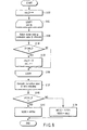
- the assumable maximum value is set to a variable min_D (step S101).
- LOOP1 step S102 shows a repetition process for use in selection of a predictive scheme in interframe encoding.
- Variable i represents a value of the index shown in FIG. 3.
- the evaluation value D of each index (combination of a reference frame number with a predictive parameter) is computed from the number of encoded bits concerning motion vector information 214 (the number of encoded bits of the variable-length code output from the variable length coding device 111 in correspondence with the motion vector information 214) and a prediction error absolute value sum, so that the optimum motion vector can be derived every predictive scheme.
- a motion vector which makes the evaluation value D a minimum value is selected (step S103). This evaluation value D is compared with min_D (step S104). If the evaluation value D is smaller than min_D, the evaluation value D is assumed min_D, and the index i is substituted in min_i (step S105).
- the evaluation value D in the case of intraframe encoding is computed (step S106). This evaluation value D is compared with min_D (step S107). If, as a result of this comparison, min_D is smaller, the mode MODE is determined to be an interframe encoding, and min_i is substituted in index information INDEX (step S108). If the evaluation value D is smaller, the mode MODE is determined to be an intraframe encoding (step S109). The evaluation value D assumes an estimated value of the number of encoded bits at the same quantization step size.
- FIG. 9 shows configuration of the video decoding apparatus related to the present embodiment.
- Coded data 300 sent out from the video encoding apparatus of the configuration shown in FIG. 1 and passed through a transmission system or a storage system is saved in an input buffer 301 once.
- the coded data 300 of the input buffer 301 is divided based on syntax by a demultiplexer 302 for each frame, and then input to the variable length decoder 303.
- the variable length decoder 303 decodes the variable-length code of each syntax of the coded data 300 to reproduce quantized orthogonal transformed coefficients, mode information 413, motion vector information 414 and index information 415.
- the quantized orthogonal transformed coefficient of the reproduced information is dequantized with the dequantizer 304.
- the dequantized coefficient is subjected to an inverse-orthogonal transformation with the inverse orthogonal transformer 305.
- a playback image signal is output from the inverse orthogonal transformer 305, and output as an ultimate playback image signal 310 via the adder 306.
- a mode selection switch 308 is turned on.
- the playback image signal 310 is output by adding the predictive error signal and the predictive image signal 412 output from the frame memory / predictive image generator 308 with the adder 306.
- the playback image signal 310 is stored in the frame memory / predictive image generator 308 as a reference image signal.
- the mode information 413, motion vector information 414 and index information 415 are input to the frame memory / predictive image generator 308.
- the mode information 413 is input to the mode selection switch 309, which is turned on in the case of the interframe encoding mode and turned off in the case of the intraframe encoding mode.
- the frame memory / predictive image generator 308 prepares for a table a plurality of combinations of the reference image number and predictive parameter that are prepared similarly to the frame memory / predictive image generator 108 of the encoding side as shown in FIG. 1, and selects one combination designated by the index information 415 from the table.
- the image signal (playback image signal 310) of the reference image designated by the reference image number of the selected combination is subjected to a linear sum according to the predictive parameter of the selected combination. Further, the offset according to the predictive parameter is added to the reproduced image signal 310. As a result, a reference image signal is generated. Thereafter, the predictive image signal 412 is generated by subjecting the generated reference image signal to motion compensation using a motion vector indicated by the motion vector information 414.
- FIG. 10 shows detailed configuration of the frame memory / predictive image generator 308 in FIG. 9.
- the reproduced image signal 310 output from the adder 306 in FIG. 9 is stored in the frame memory set 402 with control by a memory controller 401.
- the frame memory set 402 comprises a plurality of (N) frame memories FM1 to FMN to save temporally the playback image signal 310 as a reference image.
- the predictive parameter controller 403 prepares as a table combination of a reference image number with a predictive parameter as shown in FIG. 3 beforehand, and selects combination of the reference image number of the reference image used for generation of the predictive image signal 412 with the predictive parameter based on the index information 415 from the variable length decoders 303 in FIG. 9.
- a plurality of frame motion compensators 404 generates a reference image signal according to combination of the reference image number with the index information which is selected by the predictive parameter controller 403.
- the predictive image signal 412 is generated by subjecting the reference image signal to motion compensation in units of a block according to a motion vector indicated by the motion vector information 414 from the variable length decoder 303 in FIG. 9.
- FIG. 11 shows an example of syntax when encoding index information in each block.
- Each block has mode information MODE. It is determined whether index information IDi indicating a value of the index i and index information IDj indicating a value of the index j are encoded according to the mode information MODE. After encoded index information, motion vector information MVi for motion compensated prediction of the index i and motion vector information MVi for motion compensated prediction of index i and index j is encoded as motion vector information of each block.
- FIG. 12 shows an example of a concrete encoding bit stream every block when generating a predictive image using a single reference image.
- Index information IDi is disposed following the mode information MODE and motion vector information MVi is disposed thereafter.
- the motion vector information MVi is usually two-dimensional vector information. Further, a plurality of two-dimensional vectors may be send depending upon the motion compensation method in the block that is designated by the mode information.
- FIG. 13 shows an example of a concrete encoding bit stream every block when generating a predictive image using two reference images.
- Index information IDi and index information IDj are disposed following mode information MODE, and motion vector information MVi and motion vector information MVj are disposed thereafter.
- the motion vector information MVi and the motion vector information j are usually two-dimensional vector information. Further, a plurality of two-dimensional vectors may be send depending upon the motion compensation method in the block that is designated by the mode information.
- the predictive image when a predictive image is generated using a single reference image, the predictive image is generated by a linear prediction using a predictive coefficient and an offset as the predictive parameters.
- This method permits generation of an appropriate predictive image for a field image corresponding to an image obtained by combining monochrome images.
- the multiplication per pixel when there is a plurality of reference images, the multiplication per pixel must be performed a plurality of times. This increases an amount of computation.
- the necessary multiplication may be one time per pixel.
- the predictive image is generated by means of two reference images
- the predictive image is generated by obtaining weighted mean of the two reference images, using a weighting factor and an offset that are obtained from a distance between the two reference images.
- This method makes it possible to generate an appropriate predictive image for a dissolve image in which two images are mixed.
- a necessary multiplication may be one time per pixel.
- an appropriate predictive image can be generated for a feed image as well as a dissolve image by one time of multiplication per pixel. Since the multiplication can be completed one time per pixel, a hardware scale and an operation cost can be decreased in both of an encoding side and a decoding side.
- the method of generating a predictive image is changed according to the number of reference images.
- the method of generating a predictive image may be changed in units of image or in units of slice according to a difference of a prediction type as referred to as so-called a picture type or a slice type.
- a picture type or a slice type a difference of a prediction type as referred to as so-called a picture type or a slice type.
- a predictive image generating procedure using a method of changing a predictive image generating method according to a difference of the predictive type as well as the number of reference images is described with reference to FIG. 14.
- a method of generating a predictive image is changed in units of slice.
- a predictive type (referred to a slice type) of a to-be-encoded slice which is a to-be-encoded region is determined, and it is divided into three slices, that is, an I slice in which a to-be-encoded slice is subjected to an intraframe encoding (intraframe prediction), a P slice which is predicted using a single reference image (one way prediction), and a B slice which is predicted using maximum two reference images (bidirectional prediction) (step S201).
- intraframe prediction intraframe prediction
- P slice which is predicted using a single reference image
- B slice which is predicted using maximum two reference images
- the intraframe encoding (intraframe encoding) is done (step S202). If the to-be-encoded slice is a P slice, a predictive scheme based on combination of one reference image and a predictive parameter as described above is adopted (step S203).
- the to-be-encoded slice a B slice
- the number of reference images is checked (step S204), and the predictive scheme is changed according to the result.
- the to-be-encoded slice is a B slice, and the reference image is single
- normal motion compensative prediction is adopted (step S205).
- the to-be-encoded slice is a B slice, and two reference images are used, a predictive scheme corresponding to an image-to-image distance of the two reference images is adopted (step S206).
- Equation (21) is a predictive equation of a bidirectional prediction of so-called B picture using two reference images, and a first method of averaging the motion compensative predictive image of two reference images simply.
- P ( R ( i ) + R ( j ) + 1) >> 1
- change information for changing between a predictive equation shown by either of equations (4) to (6), equations (7) to (8), equation (9) or equations (10) to (20) and a predictive equation shown by an equation (21) are encoded along with the encoded data in a predetermined encoding unit such as a picture, a frame, a field and a slice, and transmitted from a video encoding apparatus to a decoding apparatus to be shared with both apparatuses.
- a predictive equation shown in either of the equations (4) to (6), equations (7) and (8), equation (10) or equations (10) to (20) and a predictive equation shown by the equation (21) are changed as needed.
- a weighted mean depending on an image-to-image distance and a simple average of the reference images can be adoptively changed, whereby the improvement of a predictive efficient can be expected. Because the equation (21) includes no multiplication, an computational amount is not increased.
- the equations (22) to (27) and equations (28) to (33) show a method of generating a predictive parameter for two reference images using a predictive parameter when the reference image is single.
- the present embodiment shows an example which these methods are combined with the first embodiment.
- the equations (22) to (27) show a second method of obtaining a predictive value by averaging the value of the predictive equation when the reference image is single.
- PY(i), PCb(i) and PCr(i) are results in the middle of a predictive value of luminance signal Y, color-difference signal Cb and color-difference signal Cr respectively.
- change information for changing between a predictive equation shown by either of equations (4) to (6), equations (7) to (8), equation (9) or equations (10) to (20) and a predictive equation shown by equations (22) to (27) are encoded along with the encoded data in a predetermined encoding unit such as a picture, a frame, a field and a slice, and transmitted from a video encoding apparatus to a decoding apparatus to be shared with both apparatuses.
- a predictive equation shown in either of the equations (4) to (6), equations (7) and (8), equation (9) or equations (10) to (20) and a predictive equation shown by the equations (22) to (27) are changed as needed.
- a weighted mean depending on an image-to-image distance and a predictive image based on a linear prediction using two reference images simple can be adoptively changed, whereby the improvement of a predictive efficient can be expected.
- the predictive type shown in the equations (22) to (27) although the multiplication number per pixel is twice, there is the merit that the degrees of freedom of the predictive coefficient increases. Therefore, further improvement of the predictive efficiency can be expected.
- Equations (28) to (33) show as another predictive equation an example of a linear predictive equation using two reference images generated using two predictive parameters in the case of a single reference image.
- change information for changing between a predictive equation shown by either of equations (4) to (6), equations (7) to (8), equation (9) or equations (10) to (20) and a predictive equation shown by equations (28) to (33) are encoded along with the encoded data in a predetermined encoding unit such as a picture, a frame, a field and a slice, and transmitted from a video encoding apparatus to a decoding apparatus to be shared with both apparatuses.
- a predictive equation shown in either of the equations (4) to (6), equations (7) and (8), equation (9) or equations (10) to (20) and a predictive equation shown by the equations (28) to (33) are changed as needed.
- a weighted mean depending on an image-to-image distance and a predictive image based on a linear prediction using two reference images can be adoptively changed, whereby the improvement of a predictive efficient can be expected.
- the predictive type shown in the equations (28) to (33) although the multiplication number per pixel is twice, there is the merit that the degrees of freedom of the predictive coefficient increases. Therefore, further improvement of the predictive efficiency can be expected.
- the above embodiment is explained as an example of a video encoding / decoding system using orthogonal transformation in units of block.
- the method of the present invention described in the above embodiment can be adopted to a case with the use of another transformation technique such as wavelet transformation.
- a process of video encoding and decoding concerning the present invention may be realized as a hardware (apparatus), and may be executed by a computer using software. A part of the process may be realized with a hardware, and the other thereof may be executed by software. Consequently, according to the present invention, there can be provided a program to make a computer execute a video encoding or a decoding process or a storage medium stored the program.
- a video encoding / decoding can perform with a high efficient and a little computational amount by doing an appropriate prediction for a video image whose luminance varies in terms of time such as a fading image and a dissolve image in particular.
Landscapes
- Engineering & Computer Science (AREA)
- Multimedia (AREA)
- Signal Processing (AREA)
- Compression Or Coding Systems Of Tv Signals (AREA)
- Compression, Expansion, Code Conversion, And Decoders (AREA)
Priority Applications (1)
| Application Number | Priority Date | Filing Date | Title |
|---|---|---|---|
| EP20060025599 EP1763253A3 (de) | 2002-11-22 | 2003-11-18 | Bewegtbilddekodierungsverfahren und -gerät |
Applications Claiming Priority (3)
| Application Number | Priority Date | Filing Date | Title |
|---|---|---|---|
| JP2002339931A JP2004179687A (ja) | 2002-11-22 | 2002-11-22 | 動画像符号化/復号化方法及び装置 |
| JP2002339931 | 2002-11-22 | ||
| PCT/JP2003/014658 WO2004049728A1 (ja) | 2002-11-22 | 2003-11-18 | 動画像符号化/復号化方法及び装置 |
Related Child Applications (1)
| Application Number | Title | Priority Date | Filing Date |
|---|---|---|---|
| EP20060025599 Division EP1763253A3 (de) | 2002-11-22 | 2003-11-18 | Bewegtbilddekodierungsverfahren und -gerät |
Publications (2)
| Publication Number | Publication Date |
|---|---|
| EP1565001A1 true EP1565001A1 (de) | 2005-08-17 |
| EP1565001A4 EP1565001A4 (de) | 2006-01-18 |
Family
ID=32375793
Family Applications (2)
| Application Number | Title | Priority Date | Filing Date |
|---|---|---|---|
| EP20060025599 Ceased EP1763253A3 (de) | 2002-11-22 | 2003-11-18 | Bewegtbilddekodierungsverfahren und -gerät |
| EP03772862A Withdrawn EP1565001A4 (de) | 2002-11-22 | 2003-11-18 | Codierungs-/decodierungsverfahren für bewegliche bilder und einrichtung |
Family Applications Before (1)
| Application Number | Title | Priority Date | Filing Date |
|---|---|---|---|
| EP20060025599 Ceased EP1763253A3 (de) | 2002-11-22 | 2003-11-18 | Bewegtbilddekodierungsverfahren und -gerät |
Country Status (12)
| Country | Link |
|---|---|
| US (8) | US7616691B2 (de) |
| EP (2) | EP1763253A3 (de) |
| JP (1) | JP2004179687A (de) |
| KR (2) | KR100728263B1 (de) |
| CN (3) | CN101090493B (de) |
| AU (1) | AU2003280847B2 (de) |
| BR (1) | BRPI0307635A8 (de) |
| CA (1) | CA2473771C (de) |
| MX (1) | MXPA04008392A (de) |
| NO (2) | NO341761B1 (de) |
| SG (1) | SG106261A1 (de) |
| WO (1) | WO2004049728A1 (de) |
Cited By (4)
| Publication number | Priority date | Publication date | Assignee | Title |
|---|---|---|---|---|
| US7961785B2 (en) | 2004-03-12 | 2011-06-14 | Thomson Licensing | Method for encoding interlaced digital video data |
| CN101729898B (zh) * | 2009-11-16 | 2011-06-15 | 中国人民解放军国防科学技术大学 | 视频编码、解码方法与视频编码、解码装置 |
| CN103200408A (zh) * | 2013-04-23 | 2013-07-10 | 华录出版传媒有限公司 | 一种视频编解码方法 |
| US8995276B2 (en) | 2010-04-13 | 2015-03-31 | Telefonaktiebolaget L M Ericsson (Publ) | Method and an arrangement in a first network node for managing congestion |
Families Citing this family (40)
| Publication number | Priority date | Publication date | Assignee | Title |
|---|---|---|---|---|
| EP1827027A1 (de) * | 2002-01-18 | 2007-08-29 | Kabushiki Kaisha Toshiba | Verfahren und Vorrichtung zur Videokodierung sowie Verfahren und Vorrichtung zur Videodekodierung |
| JP4015934B2 (ja) * | 2002-04-18 | 2007-11-28 | 株式会社東芝 | 動画像符号化方法及び装置 |
| JP2004007379A (ja) * | 2002-04-10 | 2004-01-08 | Toshiba Corp | 動画像符号化方法及び動画像復号化方法 |
| KR100969057B1 (ko) * | 2002-08-08 | 2010-07-09 | 파나소닉 주식회사 | 동화상의 부호화 방법 및 복호화 방법 |
| JP2004179687A (ja) * | 2002-11-22 | 2004-06-24 | Toshiba Corp | 動画像符号化/復号化方法及び装置 |
| JP2005318297A (ja) * | 2004-04-28 | 2005-11-10 | Toshiba Corp | 動画像符号化・復号方法及び装置 |
| JP4284265B2 (ja) * | 2004-11-02 | 2009-06-24 | 株式会社東芝 | 動画像符号化装置、動画像符号化方法、動画像復号化装置および動画像復号化方法 |
| JP4236654B2 (ja) * | 2005-09-13 | 2009-03-11 | 株式会社東芝 | 動画像符号化装置及びその方法 |
| JP5006633B2 (ja) * | 2006-03-10 | 2012-08-22 | キヤノン株式会社 | 画像符号化装置、画像符号化方法、プログラム及び記憶媒体 |
| TWI345915B (en) * | 2006-12-29 | 2011-07-21 | Nat Univ Tsing Hua | Method of motion estimation for image compression |
| BRPI0809255A2 (pt) * | 2007-04-16 | 2014-09-23 | Toshiba Kk Toshiba Corp | Método e aparelho para a codificação e decodificação de vídeo |
| CN101316198B (zh) * | 2007-06-01 | 2012-07-04 | 中兴通讯股份有限公司 | 基于索引的多媒体数据的监测方法 |
| JP4325708B2 (ja) * | 2007-07-05 | 2009-09-02 | ソニー株式会社 | データ処理装置、データ処理方法およびデータ処理プログラム、符号化装置、符号化方法および符号化プログラム、ならびに、復号装置、復号方法および復号プログラム |
| US8144213B2 (en) * | 2008-02-04 | 2012-03-27 | Panasonic Corporation | Imaging device, integrated circuit, and imaging method for encoding image frames based on detected flicker of a light source |
| CN101516028B (zh) * | 2008-02-18 | 2011-05-11 | 昊迪移通(北京)技术有限公司 | 一种针对移动网视频通话应用的高效视频编码技术 |
| JP5007259B2 (ja) * | 2008-03-27 | 2012-08-22 | ルネサスエレクトロニクス株式会社 | 画像符号化装置 |
| JP2010010915A (ja) * | 2008-06-25 | 2010-01-14 | Sony Corp | 画像処理装置および方法、並びにプログラム |
| JP2011109172A (ja) * | 2009-11-12 | 2011-06-02 | Hitachi Kokusai Electric Inc | 映像符号化装置、および、そのデータ処理方法 |
| USRE48074E1 (en) * | 2010-02-24 | 2020-06-30 | Velos Media, Llc | Image encoding device and image decoding device |
| FR2957744B1 (fr) * | 2010-03-19 | 2012-05-25 | Canon Kk | Procede de traitement d'une sequence video et dispositif associe |
| CN103813163B (zh) * | 2010-04-08 | 2017-03-01 | 株式会社东芝 | 图像解码方法以及图像解码装置 |
| JP5368631B2 (ja) | 2010-04-08 | 2013-12-18 | 株式会社東芝 | 画像符号化方法、装置、及びプログラム |
| JP5805991B2 (ja) * | 2010-05-07 | 2015-11-10 | トムソン ライセンシングThomson Licensing | ピクチャ・シーケンスを符号化する方法、それに対応する再構築方法、および当該シーケンスを表す符号化データのストリーム |
| US8908755B2 (en) * | 2010-07-16 | 2014-12-09 | Sony Corporation | Multi-parameter motion for efficient prediction in video compression |
| CN108055538B (zh) | 2011-01-13 | 2021-10-29 | 日本电气株式会社 | 视频编码设备以及视频编码方法 |
| BR122020003041B1 (pt) | 2011-10-17 | 2021-11-09 | Kabushiki Kaisha Toshiba | Método de codificação, método de decodificação e dispositivo de transferência |
| JP5592023B2 (ja) | 2011-10-17 | 2014-09-17 | 株式会社東芝 | 符号化方法及び符号化装置 |
| WO2013069117A1 (ja) * | 2011-11-09 | 2013-05-16 | 株式会社東芝 | 予測画像生成方法、符号化方法及び復号方法 |
| EP2801194B1 (de) * | 2012-01-09 | 2021-10-27 | Huawei Technologies Co., Ltd. | Quantisierungsmatrix (qm)-codierung auf basis einer gewichteten prädiktion |
| CN103348678B (zh) * | 2012-02-07 | 2017-06-27 | 松下知识产权经营株式会社 | 图像处理装置以及图像处理方法 |
| US11039138B1 (en) | 2012-03-08 | 2021-06-15 | Google Llc | Adaptive coding of prediction modes using probability distributions |
| EP3193506A1 (de) | 2012-06-27 | 2017-07-19 | Kabushiki Kaisha Toshiba | Dekodierungsverfahren und -vorrichtung |
| US10003793B2 (en) | 2012-10-01 | 2018-06-19 | Google Technology Holdings LLC | Processing of pulse code modulation (PCM) parameters |
| WO2015086717A2 (en) * | 2013-12-10 | 2015-06-18 | Canon Kabushiki Kaisha | Improved palette mode in hevc |
| PL3425914T3 (pl) | 2013-12-10 | 2022-02-14 | Canon Kabushiki Kaisha | Sposób i aparatura do kodowania lub dekodowania palety w trybie kodowania palety |
| US10805627B2 (en) | 2015-10-15 | 2020-10-13 | Cisco Technology, Inc. | Low-complexity method for generating synthetic reference frames in video coding |
| CN109076242B (zh) * | 2016-05-13 | 2023-01-03 | 索尼公司 | 图像处理设备和方法 |
| US10136155B2 (en) | 2016-07-27 | 2018-11-20 | Cisco Technology, Inc. | Motion compensation using a patchwork motion field |
| CN108243339B (zh) * | 2016-12-27 | 2021-02-26 | 浙江大学 | 图像编解码方法及装置 |
| US10412410B2 (en) | 2017-08-14 | 2019-09-10 | Google Llc | Compound motion-compensated prediction |
Family Cites Families (31)
| Publication number | Priority date | Publication date | Assignee | Title |
|---|---|---|---|---|
| US4851906A (en) * | 1986-11-04 | 1989-07-25 | Nec Corporation | Data compression using orthogonal transform and vector quantization |
| JP2530217B2 (ja) | 1989-01-20 | 1996-09-04 | 日本ビクター株式会社 | フレ―ム間予測符号化装置及び復号装置 |
| DE4322343C2 (de) | 1992-07-06 | 1996-10-02 | Mitsubishi Electric Corp | Mittel zum Erfassen eines Bewegungsvektors und Verfahren zum Bestimmen eines Bewegungsvektors |
| US5561477A (en) * | 1994-10-26 | 1996-10-01 | Thomson Consumer Electronics, Inc. | System for coding a video signal in the presence of an image intensity gradient |
| JPH08223577A (ja) * | 1994-12-12 | 1996-08-30 | Sony Corp | 動画像符号化方法及び装置、並びに動画像復号方法及び装置 |
| US5903313A (en) * | 1995-04-18 | 1999-05-11 | Advanced Micro Devices, Inc. | Method and apparatus for adaptively performing motion compensation in a video processing apparatus |
| US5774593A (en) * | 1995-07-24 | 1998-06-30 | University Of Washington | Automatic scene decomposition and optimization of MPEG compressed video |
| KR0172902B1 (ko) * | 1995-09-12 | 1999-03-20 | 구자홍 | 엠펙 ii 부호기 |
| JPH09121358A (ja) * | 1995-10-25 | 1997-05-06 | Matsushita Electric Ind Co Ltd | 画像符号化及び復号化装置と方法 |
| JPH09163376A (ja) * | 1995-12-05 | 1997-06-20 | Nippon Telegr & Teleph Corp <Ntt> | 動画像のフレーム間符号化・復号方法および装置 |
| JP3876392B2 (ja) * | 1996-04-26 | 2007-01-31 | 富士通株式会社 | 動きベクトル探索方法 |
| US6266370B1 (en) * | 1996-09-03 | 2001-07-24 | Nippon Telegraph And Telephone Corporation | Brightness-variation compensation method and coding/decoding apparatus for moving pictures |
| JP2938412B2 (ja) * | 1996-09-03 | 1999-08-23 | 日本電信電話株式会社 | 動画像の輝度変化補償方法、動画像符号化装置、動画像復号装置、動画像符号化もしくは復号プログラムを記録した記録媒体および動画像の符号化データを記録した記録媒体 |
| KR100480686B1 (ko) | 1997-01-27 | 2005-05-16 | 엘지전자 주식회사 | 고선명영상의장면전환검출방법 |
| JPH10224795A (ja) * | 1997-01-31 | 1998-08-21 | Nippon Telegr & Teleph Corp <Ntt> | 動画像符号化方法、復号方法、符号化器および復号器 |
| JPH11239351A (ja) * | 1998-02-23 | 1999-08-31 | Nippon Telegr & Teleph Corp <Ntt> | 動画像符号化方法、復号方法、符号化器、復号器、動画像符号化プログラムおよび動画像復号プログラムを記録した記録媒体 |
| US6411651B1 (en) * | 1998-06-26 | 2002-06-25 | Compaq Information Technologies Group, L.P. | Method and system for distributed video compression in personal computer architecture |
| JP3166716B2 (ja) | 1998-08-12 | 2001-05-14 | 日本電気株式会社 | フェード画像対応動画像符号化装置及び符号化方法 |
| US6954499B2 (en) * | 2000-03-15 | 2005-10-11 | Victor Company Of Japan, Ltd | Moving picture coding, coded-moving picture bitstream conversion and coded-moving picture bitstream multiplexing |
| US7116372B2 (en) * | 2000-10-20 | 2006-10-03 | Matsushita Electric Industrial Co., Ltd. | Method and apparatus for deinterlacing |
| JP2004532540A (ja) * | 2001-03-05 | 2004-10-21 | インタービデオインコーポレイテッド | 誤り耐性のある符号化のためのシステム及び方法 |
| US6890101B2 (en) * | 2001-07-10 | 2005-05-10 | Dan Blau | Transparent bag with card holder |
| US7266150B2 (en) * | 2001-07-11 | 2007-09-04 | Dolby Laboratories, Inc. | Interpolation of video compression frames |
| US6816552B2 (en) * | 2001-07-11 | 2004-11-09 | Dolby Laboratories Licensing Corporation | Interpolation of video compression frames |
| JP4015934B2 (ja) | 2002-04-18 | 2007-11-28 | 株式会社東芝 | 動画像符号化方法及び装置 |
| EP1827027A1 (de) | 2002-01-18 | 2007-08-29 | Kabushiki Kaisha Toshiba | Verfahren und Vorrichtung zur Videokodierung sowie Verfahren und Vorrichtung zur Videodekodierung |
| JP2004007379A (ja) | 2002-04-10 | 2004-01-08 | Toshiba Corp | 動画像符号化方法及び動画像復号化方法 |
| KR100508798B1 (ko) * | 2002-04-09 | 2005-08-19 | 엘지전자 주식회사 | 쌍방향 예측 블록 예측 방법 |
| US7376186B2 (en) * | 2002-07-15 | 2008-05-20 | Thomson Licensing | Motion estimation with weighting prediction |
| KR100969057B1 (ko) * | 2002-08-08 | 2010-07-09 | 파나소닉 주식회사 | 동화상의 부호화 방법 및 복호화 방법 |
| JP2004179687A (ja) * | 2002-11-22 | 2004-06-24 | Toshiba Corp | 動画像符号化/復号化方法及び装置 |
-
2002
- 2002-11-22 JP JP2002339931A patent/JP2004179687A/ja active Pending
-
2003
- 2003-11-18 MX MXPA04008392A patent/MXPA04008392A/es active IP Right Grant
- 2003-11-18 SG SG200404522A patent/SG106261A1/en unknown
- 2003-11-18 CN CN200710102503XA patent/CN101090493B/zh not_active Expired - Fee Related
- 2003-11-18 KR KR1020067013856A patent/KR100728263B1/ko not_active Expired - Fee Related
- 2003-11-18 CN CNA200380100231XA patent/CN1692653A/zh active Pending
- 2003-11-18 KR KR20047011874A patent/KR100671452B1/ko not_active Expired - Fee Related
- 2003-11-18 WO PCT/JP2003/014658 patent/WO2004049728A1/ja not_active Ceased
- 2003-11-18 BR BRPI0307635A patent/BRPI0307635A8/pt active IP Right Grant
- 2003-11-18 CN CN2007101025044A patent/CN101090494B/zh not_active Expired - Fee Related
- 2003-11-18 EP EP20060025599 patent/EP1763253A3/de not_active Ceased
- 2003-11-18 EP EP03772862A patent/EP1565001A4/de not_active Withdrawn
- 2003-11-18 CA CA2473771A patent/CA2473771C/en not_active Expired - Lifetime
- 2003-11-18 AU AU2003280847A patent/AU2003280847B2/en not_active Ceased
-
2004
- 2004-07-23 US US10/896,890 patent/US7616691B2/en not_active Expired - Lifetime
- 2004-08-16 NO NO20043410A patent/NO341761B1/no not_active IP Right Cessation
-
2007
- 2007-03-13 US US11/685,565 patent/US7599437B2/en not_active Expired - Lifetime
-
2009
- 2009-09-03 US US12/553,235 patent/US7885332B2/en not_active Expired - Lifetime
- 2009-09-03 US US12/553,116 patent/US7949048B2/en not_active Expired - Lifetime
- 2009-09-03 US US12/553,114 patent/US7944973B2/en not_active Expired - Lifetime
- 2009-09-03 US US12/553,851 patent/US7903740B2/en not_active Expired - Lifetime
- 2009-09-03 US US12/553,247 patent/US7885333B2/en not_active Expired - Lifetime
- 2009-09-03 US US12/553,111 patent/US7944972B2/en not_active Expired - Lifetime
-
2015
- 2015-08-14 NO NO20151026A patent/NO341757B1/no not_active IP Right Cessation
Non-Patent Citations (2)
| Title |
|---|
| No further relevant documents disclosed * |
| See also references of WO2004049728A1 * |
Cited By (5)
| Publication number | Priority date | Publication date | Assignee | Title |
|---|---|---|---|---|
| US7961785B2 (en) | 2004-03-12 | 2011-06-14 | Thomson Licensing | Method for encoding interlaced digital video data |
| CN101729898B (zh) * | 2009-11-16 | 2011-06-15 | 中国人民解放军国防科学技术大学 | 视频编码、解码方法与视频编码、解码装置 |
| US8995276B2 (en) | 2010-04-13 | 2015-03-31 | Telefonaktiebolaget L M Ericsson (Publ) | Method and an arrangement in a first network node for managing congestion |
| CN103200408A (zh) * | 2013-04-23 | 2013-07-10 | 华录出版传媒有限公司 | 一种视频编解码方法 |
| CN103200408B (zh) * | 2013-04-23 | 2016-03-30 | 华录出版传媒有限公司 | 一种视频编解码方法 |
Also Published As
Similar Documents
| Publication | Publication Date | Title |
|---|---|---|
| EP1565001A1 (de) | Codierungs-/decodierungsverfahren für bewegliche bilder und einrichtung | |
| EP1798988B1 (de) | Verfahren und Vorrichtung zur Videdekodierung |
Legal Events
| Date | Code | Title | Description |
|---|---|---|---|
| PUAI | Public reference made under article 153(3) epc to a published international application that has entered the european phase |
Free format text: ORIGINAL CODE: 0009012 |
|
| 17P | Request for examination filed |
Effective date: 20040715 |
|
| AK | Designated contracting states |
Kind code of ref document: A1 Designated state(s): AT BE BG CH CY CZ DE DK EE ES FI FR GB GR HU IE IT LI LU MC NL PT RO SE SI SK TR |
|
| AX | Request for extension of the european patent |
Extension state: AL LT LV MK |
|
| A4 | Supplementary search report drawn up and despatched |
Effective date: 20051205 |
|
| DAX | Request for extension of the european patent (deleted) | ||
| STAA | Information on the status of an ep patent application or granted ep patent |
Free format text: STATUS: THE APPLICATION IS DEEMED TO BE WITHDRAWN |
|
| 18D | Application deemed to be withdrawn |
Effective date: 20141223 |