EP1564980A1 - Akustischer Echokompensator - Google Patents
Akustischer Echokompensator Download PDFInfo
- Publication number
- EP1564980A1 EP1564980A1 EP05002907A EP05002907A EP1564980A1 EP 1564980 A1 EP1564980 A1 EP 1564980A1 EP 05002907 A EP05002907 A EP 05002907A EP 05002907 A EP05002907 A EP 05002907A EP 1564980 A1 EP1564980 A1 EP 1564980A1
- Authority
- EP
- European Patent Office
- Prior art keywords
- microphone
- processing
- sound
- signal
- microphones
- Prior art date
- Legal status (The legal status is an assumption and is not a legal conclusion. Google has not performed a legal analysis and makes no representation as to the accuracy of the status listed.)
- Withdrawn
Links
Images









Classifications
-
- H—ELECTRICITY
- H04—ELECTRIC COMMUNICATION TECHNIQUE
- H04R—LOUDSPEAKERS, MICROPHONES, GRAMOPHONE PICK-UPS OR LIKE ACOUSTIC ELECTROMECHANICAL TRANSDUCERS; ELECTRIC HEARING AIDS; PUBLIC ADDRESS SYSTEMS
- H04R1/00—Details of transducers, loudspeakers or microphones
- H04R1/20—Arrangements for obtaining desired frequency or directional characteristics
- H04R1/32—Arrangements for obtaining desired frequency or directional characteristics for obtaining desired directional characteristic only
-
- H—ELECTRICITY
- H04—ELECTRIC COMMUNICATION TECHNIQUE
- H04M—TELEPHONIC COMMUNICATION
- H04M9/00—Arrangements for interconnection not involving centralised switching
- H04M9/08—Two-way loud-speaking telephone systems with means for conditioning the signal, e.g. for suppressing echoes for one or both directions of traffic
- H04M9/082—Two-way loud-speaking telephone systems with means for conditioning the signal, e.g. for suppressing echoes for one or both directions of traffic using echo cancellers
Definitions
- the present invention relates to a sound pickup apparatus and a method preferable for use when, for example, a plurality of conference participants in two distant conference rooms hold an audio teleconference by using a plurality of microphones, or hold a voice + television conference by adding a video further.
- the present invention relates to a sound pickup apparatus and a method to improve defects of an echo cancellation processing arising in switching an internal processing of an echo canceller to the internal processing for a new microphone immediately when a microphone is switched in a sound pickup apparatus performing an echo cancellation processing by one echo canceller for a plurality of microphones.
- a TV conference system having a sound pickup apparatus or a sound pickup apparatus that a picture image is added has been used to enable conference participants in two conference rooms at distant location to hold a conference.
- a microphone is selected, where the microphone is used by a speaking person whose voice should be transmitted to a conference room of the other party among the speaking persons using a plurality of microphones.
- one echo canceller is set for a plurality of microphones. Because, although the echo canceller is possible to process at high speed usually, since it is realized by an expensive digital signal processor (DSP), the echo cancellation processing of a plurality of microphones is performed by one echo canceller.
- DSP digital signal processor
- the echo canceller performs the echo cancellation with performing a learning processing about a sound from the selected microphone. Therefore, in the echo canceller, learning data for an echo cancellation of each microphone is held.
- one echo canceller performs an echo cancel processing of a plurality of microphones, further when switching from the first microphone to the second microphone is performed, if switching learning data in the echo canceller to learning data for the second microphone immediately, an occurrence that a voice from the second microphone is performed the echo cancellation processing with the learning data for the first microphone is arisen.
- the learning data for each microphone obtained by the learning processing in the echo canceller is based on sound data obtained ongoingly for predetermined time.
- An object of the present invention is to provide a sound pickup apparatus and a method to prevent a false echo cancellation processing when switching from the first microphone to the second microphone in a sound pickup apparatus performing an echo cancellation processing to a plurality of microphone with one echo canceller.
- a sound pickup apparatus having a plurality of microphones placed based on a predetermined condition, a microphone selector detecting sound pickup signals of a plurality of the microphones and selecting the microphone having detected an effective sound pickup signal among the detected sound pickup signals, an echo cancellation processor performing an echo cancellation processing about the sound signal of the selected microphone, and an echo cancellation processing controller stopping the echo cancellation processing for a predetermined period when switching the sound signal of the microphone.
- the microphone selector cross-fades a sound signal of a microphone selected before and a sound signal of a new microphone when outputting by selecting a sound pickup signal of a new microphone, and the echo cancellation processing controller stops the echo cancellation processing in the cross-fading period.
- a sound pickup method having a microphone selection step of detecting sound pickup signals of a plurality of microphones placed based on a predetermined condition and selecting the microphone having detected an effective sound pickup signal among the detected sound pickup signals, an echo cancellation processing step of performing an echo cancellation processing about the sound signal of the selected microphone, and an echo cancellation processing control step of stopping the echo cancellation processing for a predetermined period when switching the sound signal of the microphone in the microphone selection step.
- an unnatural echo cancellation processing can be avoided by stopping an echo cancellation processing in selecting (changing) microphones.
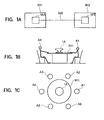
- FIGS. 1A to 1C are views of the configuration showing an example to which the sound pickup apparatus of the embodiment of the present invention is applied.
- sound pickup apparatus 10A and 10B are disposed in two conference rooms 901 and 902. These sound pickup apparatuses 10A and 10B are connected by a communication line 920, for example, a telephone line.
- a conversation via the communication line 920 is carried out between one speaker and another, that is, one-to-one, but in the communication apparatus of the embodiment of the present invention, a plurality of conference participants in the conference rooms 901 and 902 can converse with each other by using one communication line 920. Note that in the present embodiment, in order to avoid congestion of audio, the parties speaking at the same time (same period) are limited to one at each side.
- the sound pickup apparatus selects (identifies) a calling party and picks up audio of selected calling party.
- the picked-up audio and the imaged video are transferred to the conference room of the other side and played in the sound pickup apparatus of the other side.
- the configuration of the communication apparatus in the sound pickup apparatus according to an embodiment of the present invention will be explained referring to FIG. 2 to FIG. 4.
- the first sound pickup apparatus 10A and the second sound pickup apparatus 10B are similar.
- FIG. 2 is a perspective view of the sound pickup apparatus according to an embodiment of the present invention.
- FIG. 3 is a sectional view of the sound pickup apparatus illustrated in FIG. 2.
- FIG. 4 is a plan view of a microphone electronic circuit housing of the sound pickup apparatus illustrated in FIGS. 2and 3 and a plan view along a line X-X of FIG. 3.
- the sound pickup apparatus has an upper cover 11, a sound reflection plate 12, a coupling member 13, a speaker housing 14, and an operation unit 15.
- the speaker housing 14 has a sound reflection surface 14a, a bottom surface 14b, and an upper sound output opening 14c.
- a receiving and reproduction speaker 16 is housed in a space surrounded by the sound reflection surface 14a and the bottom surface 14b, that is, an inner cavity 14d.
- the sound reflection plate 12 is located above the speaker housing 14.
- the speaker housing 14 and the sound reflection plate 12 are connected by the coupling member 13.
- a restraint member 17 passes through the coupling member 13.
- the restraint member 17 restrains the space between a restraint member bottom fixing portion 14e of the bottom surface 14b of the speaker housing 14 and a restraint member fixing portion 12b of the sound reflection plate 12. Note that the restraint member 17 only passes through a restraint member passage 14f of the speaker housing 14. The reason why the restraint member 17 passes through the restraint member passage 14f and does not restrain it is that the speaker housing 14 vibrates by the operation of the speaker 16 and that the vibration thereof is not restricted around the upper sound output opening 14c.
- Speech by a speaking person of the other conference room passes through the receiving and reproduction speaker 16 and upper sound output opening 14c and is diffused along the space defined by the sound reflection surface 12a of the sound reflection plate 12 and the sound reflection surface 14a of the speaker housing 14 to the entire 360 degree orientation around an axis C-C.
- the cross-section of the sound reflection surface 12a of the sound reflection plate 12 draws a loose trumpet type arc as illustrated.
- the cross-section of the sound reflection surface 12a forms the illustrated sectional shape over 360 degrees (entire orientation) around the axis C-C.
- the cross-section of the sound reflection surface 14a of the speaker housing 14 draws a loose convex shape as illustrated.
- the cross-section of the sound reflection surface 14a forms the illustrated sectional shape over 360 degrees (entire orientation) around the axis C-C.
- the sound S output from the receiving and reproduction speaker 16 passes through the upper sound output opening 14c, passes through the sound output space defined by the sound reflection surface 12a and the sound reflection surface 14a and having a trumpet-like cross-section, is diffused along the surface of the table 911 on which the sound pickup apparatus is placed in the entire orientation of 360 degrees around the axis C-C, and is heard with an equal volume by all conference participants A1 to A6.
- the surface of the table 911 is utilized as part of the sound propagating means.
- the state of diffusion of the sound S output from the receiving and reproduction speaker 16 is shown by the arrows.
- the sound reflection plate 12 supports a printed circuit board 21.
- the printed circuit board 21 mounts the microphones MC1 to MC6 of the microphone electronic circuit housing 2, light emitting diodes LEDs 1 to 6, a microprocessor 23, a codec 24, a first digital signal processor (DSP) 25, a second digital signal processor (DSP) 26, an A/D converter block 27, a D/A converter block 28, an amplifier block 29, and other various types of electronic circuits.
- the sound reflection plate 12 also functions as a member for supporting the microphone electronic circuit housing 2.
- the printed circuit board 21 has dampers 18 attached to it for absorbing vibration from the receiving and reproduction speaker 16 so as to prevent vibration from the receiving and reproduction speaker 16 from being transmitted through the sound reflection plate 12, entering the microphones MC1 to MC6 etc., and becoming noise.
- Each damper 18 is comprised by a screw and a buffer material such as a vibration-absorbing rubber insert between the screw and the printed circuit board 21.
- the buffer material is fastened by the screw to the printed circuit board 21. Namely, the vibration transmitted from the receiving and reproduction speaker 16 to the printed circuit board 21 is absorbed by the buffer material. Due to this, the microphones MC1 to MC6 are not affected much by sound from the speaker 16.
- each microphone is located radially at equal angles and equal intervals (at intervals of 60 degrees) from the center axis C of the printed circuit board 21.
- Each microphone is a microphone having single directivity. The characteristic thereof will be explained later.
- Each of the microphones MC1 to MC6 is supported by a first microphone support member 22a and a second microphone support member 22b both having flexibility or resiliency so that it can freely rock (illustration is made for only the first microphone support member 22a and the second microphone support member 22b of the microphone MC1 for simplifying the illustration).
- the dampers 18 In addition to the measure of preventing the influence of vibration from the receiving and reproduction speaker 16 by the dampers 18 using the above buffer materials, by preventing the influence of vibration from the receiving and reproduction speaker 16 by absorbing the vibration of the printed circuit board 21 vibrating by the vibration from the receiving and reproduction speaker 16 by the first and second microphone support members 22a and 22b having flexibility or resiliency, noise of the receiving and reproduction speaker 16 is avoided.
- the receiving and reproduction speaker 16 is oriented vertically with respect to the center axis C-C of the plane in which the microphones MC1 to MC6 are located (oriented (directed) upward in the present embodiment).
- the distances between the receiving and reproduction speaker 16 and the microphones MC1 to MC6 become equal and the audio from the receiving and reproduction speaker 16 arrives at the microphones MC1 to MC6 with almost the same volume and same phase.
- the sound of the receiving and reproduction speaker 16 is prevented from being directly input to the microphones MC1 to MC6.
- the dampers 18 using the buffer materials, the first microphone support member 22a and the second microphone support member 22b having flexibility or resiliency, the influence of the vibration of the receiving and reproduction speaker 16 is reduced.
- the conference participants A1 to A6, as illustrated in FIG. 1C, are usually positioned at almost equal intervals in the 360 degree direction of the communication apparatus in the vicinity of the microphones MC1 to MC6 arranged at intervals of 60 degrees.
- light emission diodes LED1 to LED6 are arranged in the vicinity of the microphones MC1 to MC6.
- the light emission diodes LED1 to LED6 have to be provided so as to be able be viewed from all conference participants A1 to A6 even in a state where the upper cover 11 is attached.
- the upper cover 11 is provided with a transparent window so that the light emission states of the light emission diodes LED1 to LED6 can be viewed.
- openings can also be provided at the portions of the light emission diodes LED1 to LED6 in the upper cover 11, but the transparent window is preferred from the viewpoint for preventing dust from entering the microphone electronic circuit housing 2.
- the printed circuit board 21 is provided with a first digital processor (DSP1) 25, a second digital signal processor (DSP2) 26, and various types of electronic circuits 27 to 29 are arranged in a space other than the portion where the microphones MC1 to MC6 are located.
- DSP1 digital processor
- DSP2 digital signal processor
- the DSP 25 is used as the signal processing means for performing processing such as filter processing and microphone selection processing together with the various types of electronic circuits 27 to 29, and the DSP 26 is used as an echo canceller.
- FIG. 5 is a view of the schematic configuration of a microprocessor 23, a codec 24, the DSP 25, the DSP 26, an A/D converter block 27, a D/A converter block 28, an amplifier block 29, and other various types of electronic circuits.
- the microprocessor 23 performs the processing for overall control of the microphone electronic circuit housing 2.
- the codec 24 compresses and encodes the audio to be transmitted to the conference room of the other party.
- the DSP 25 performs the various types of signal processing explained below, for example, the filter processing and the microphone selection processing.
- the DSP 26 functions as the echo canceller.
- FIG. 5 as an example of the A/D converter block 27, four A/D converters 271 to 274 are exemplified, as an example of the D/A converter block 28, two D/A converters 281 and 282 are exemplified, and as an example of the amplifier block 29, two amplifiers 291 and 292 are exemplified.
- various types of circuits such as the power supply circuit are mounted on the printed circuit board 21.
- pairs of microphones MC1-MC4, MC2-MC5, and MC3-MC6 each arranged on a straight line at positions symmetric (or opposite) with respect to the center axis C of the printed circuit board 21 input two channels of analog signals to the A/D converters 271 to 273 for converting analog signals to digital signals.
- one A/D converter converts two channels of analog input signals to digital signals. Therefore, detection signals of two (a pair of) microphones located on a straight line straddling the center axis C, for example, the microphones MC1 and MC4, are input to one A/D converter and converted to the digital signals.
- the difference of audio of two microphones located on one straight line, the magnitude of the audio and so on are referred to. Therefore when signals of two microphones located on a straight line are input to the same A/D converter, the conversion timings become almost the same. There are therefore the advantages that the timing error is small when finding the difference of audio outputs of the two microphones, the signal processing becomes easy and so on.
- the A/D converters 271 to 274 can be configured as A/D converters 271 to 274 equipped with variable gain type amplification functions as well.
- Sound pickup signals of the microphones MC1 to MC6 converted at the A/D converters 271 to 273 are input to the DSP 25 where various types of signal processing explained later are carried out.
- the result of selection of one of the microphones MC1 to MC6 is output to the light emission diodes LED1 to LED6 as one of the examples of the microphone selection result displaying means.
- the processing result of the DSP 25 is output to the DSP 26 where the echo cancellation processing is carried out.
- the DSP 26 has for example an echo cancellation transmitter and an echo cancellation receiver.
- the processing results of the DSP 26 are converted to analog signals at the D/A converters 281 and 282.
- the output from the D/A converter 281 is encoded at the codec 24 according to need, output to a line-out terminal of the telephone line 920 (FIG. 1A) via the amplifier 291, and output as sound via the receiving and reproduction speaker 16 of the communication apparatus disposed in the conference room of the other party.
- the audio from the communication apparatus disposed in the conference room of the other party is input via the line-in terminal of the telephone line 920 (FIG. 1A), converted to a digital signal at the A/D converter 274, and input to the DSP 26 where it is used for the echo cancellation processing. Further, the audio from the communication apparatus disposed in the conference room of the other party is applied to the speaker 16 by a not illustrated route and output as sound.
- the output from the D/A converter 282 is output as sound from the receiving and reproduction speaker 16 of the communication apparatus via the amplifier 292.
- the conference participants A1 to A6 can also hear audio emitted by the speaking parties in the conference room via the receiving and reproduction speaker 16 in addition to the audio of the selected speaking person of the conference room of the other party from the receiving and reproduction speaker 16 explained above.
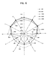
- FIG. 6 is a graph showing directivities of the microphones MC1 to MC6.
- each single directivity characteristic microphone as illustrated in FIG. 6, the frequency characteristic and the level characteristic differ according to the angle of arrival of the audio at the microphone from the speaking person.
- the plurality of curves indicate directivities when frequencies of the sound pickup signals are 100 Hz, 150 Hz, 200 Hz, 300 Hz, 400 Hz, 500 Hz, 700 Hz, 1000 Hz, 1500 Hz, 2000 Hz, 3000 Hz, 4000 Hz, 5000 Hz, and 7000 Hz. Note that for simplifying the illustration, FIG. 6 illustrates the directivity for 150 Hz, 500 Hz, 1500 Hz, 3000 Hz, and 7000 Hz as representative examples.
- FIGS. 7A to 7D are graphs showing analysis results for the position of the sound source and the sound pickup levels of the microphones and, as an example of the analysis, show results obtained by positioning the speaker a predetermined distance from the communication apparatus, for example, a distance of 1.5 meters, and applying fast Fourier transforms (FFT) to the audio picked up by the microphones at constant time intervals.
- the X-axis represents the frequency
- the Y-axis represents the signal level
- the Z-axis represents the time.
- the DSP 25 When using microphones having directivity shown in FIG. 6, a strong directivity is shown at the front surfaces of the microphones. In the present embodiment, by making good use of such a characteristic, the DSP 25 performs the selection processing of the microphones.
- a microphone array using a plurality of no directivity microphones can be used as the method for obtaining the directivity of the microphones.
- complex processing is required for matching the time axes (phases) of the plurality of signals, therefore a long time is taken, the response is low, and the hardware configuration becomes complex.
- complex signal processing is required also for the signal processing system of the DSP.
- the present invention solves such a problem by using microphones having directivity exemplified in FIG. 6.
- the sound pickup apparatus having the above configuration has the following advantages.
- the receiving and reproduction speaker 16 was arranged at the lower portion, and the microphones MC1 to MC6 (and related electronic circuits) were arranged at the upper portion, but it is also possible to vertically invert the positions of the receiving and reproduction speaker 16 and the microphones MC1 to MC6 (and related electronic circuits) as illustrated in FIG. 8. Even in such a case, the above effects are exhibited.
- the number of microphones is not limited to six. Any number of microphones, for example, four or eight, may be arranged at equal angles radially and at equal intervals about the axis C so that a plurality of pairs are located on straight lines (in the same direction), for example, like the microphones MC1 and MC4.
- the reason that two microphones, for example MC1 and MC4, are arranged on a straight line facing each other as a preferable embodiment is for selecting the microphone and identifying the speaking person.
- DSP digital signal processor
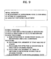
- FIG. 9 is a view schematically illustrating the processing in the sound pickup apparatus 10A performed by the DSP 25.
- the DSP 25 the DSP 25
- the noise of the surroundings where the sound pickup apparatus is disposed is measured.
- the sound pickup apparatus can be used in various environments (conference rooms).
- the noise of the surrounding environment where the sound pickup apparatus is disposed is measured to enable elimination of the influence of that noise from the signals picked up at the microphones.
- the noise is measured in advance, so this processing can be omitted when the state of the noise does not change. Note that the noise can also be measured in the normal state.
- the chairman is set from the operation unit 15 of the sound pickup apparatus.
- the first microphone MC1 located in the vicinity of the operation unit 15 is used as the chairman's microphone.
- the chairperson's microphone may be any microphone.
- the microphone at the position where the chairperson sits may be determined in advance too. In this case, no operation for selection of the chairperson is necessary each time.
- the selection of the chairperson is not limited to the initial state and can be carried out at any time.
- the gain of the amplification unit for amplifying signals of the microphones MC1 to MC6 or the attenuation value of the attenuation unit is automatically adjusted so that the acoustic couplings between the receiving and reproduction speaker 16 and the microphones MC1 to MC6 become equal.
- the DSP 25 performs processing for selecting and switching the microphone.
- the speech from the selected microphone is transmitted to the communication apparatus 1 of the conference room of the other party via the telephone line 920 and output from the speaker.
- the LED in the vicinity of the microphone of the selected speaking person turns on.
- the audio of the selected speaking person can be heard from the speaker of the communication apparatus 1 of that room as well so that it can be recognized who is the permitted speaking person.
- This processing aims to select the signal of the single directivity microphone facing to the speaking person and to send a signal having a good S/N to the other party as the transmission signal.
- Whether a microphone of the speaking person is selected and which is the microphone of the conference participant permitted to speak is made easy to recognize by all of the conference participants A1 to A6 by turning on the corresponding microphone selection result displaying means, for example, the light emission diodes LED1 to LED6.
- This processing is divided into initial processing immediately after turning on the power of the sound pickup apparatus and the normal processing.
- FIG. 10 is a view of the configuration showing the filter processing performed at the DSP 25 using the sound signals picked up by the microphones as pre-processing.
- FIG. 10 shows the processing for one microphone (channel (one sound pickup signal)).
- the sound pickup signals of microphones are processed at an analog low cut filter 101 having a cut-off frequency of for example 100 Hz, the filtered voice signals from which the frequency of 100 Hz or less was removed are output to the A/D converter 102, and the sound pickup signals converted to the digital signals at the A/D converter 102 are stripped of their high frequency components at the digital high cut filters 103a to 103e (referred to overall as 103) having cut-off frequencies of 7.5 kHz, 4 kHz, 1.5 kHz, 600 Hz, and 250 Hz (high cut processing).
- the results of the digital high cut filters 103a to 103e are further subtracted by the filter signals of the adjacent digital high cut filters 103a to 103e in the subtracters 104a to 104d (referred to overall as 104).
- the digital high cut filters 103a to 103e and the subtracters 104a to 104e are actually realized by processing in the DSP 25.
- the A/D converter 102 can be realized as part of the A/D converter block 27.
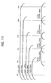
- FIG. 11 is a view of the frequency characteristic showing the filter processing result explained by referring to FIG. 10. In this way, a plurality of signals having various types of frequency components are generated from signals picked up by microphones having single directivity.
- FIG. 12 shows only one channel (CH) of the processing of six channels of input signals picked up at the microphones MC1 to MC6.
- the band-pass filter processing and level conversion processing unit in the DSP 25 have, for the channels of the sound pickup signals of the microphones, band-pass filters 201a to 201e (referred to overall as the "band-pass filter block 201") having band-pass characteristic of 100 to 600 Hz, 200 to 250 Hz, 250 to 600 Hz, 600 to 1500 Hz, 1500 to 4000 Hz, and 4000 to 7500 Hz and level converters 202a to 202g (referred to overall as the "level converter block 202”) for converting the levels of the original microphone sound pickup signals and the band-passed sound pickup signals.
- band-pass filter block 201 band-pass filter block 201e
- level converters 202a to 202g referred to overall as the "level converter block 202" for converting the levels of the original microphone sound pickup signals and the band-passed sound pickup signals.
- Each of the level conversion units 202a to 202g has a signal absolute value processing unit 203 and a peak hold processing unit 204. Accordingly, as illustrated by the waveform diagram, the signal absolute value processing unit 203 inverts the sign when receiving as input a negative signal indicated by a broken line to converts the same to a positive signal.
- the peak hold processing unit 204 holds the maximum value of the output signals of the signal absolute value processing unit 203. Note that in the present embodiment, the held maximum value drops a little along with the elapse of time. Naturally, it is also possible to improve the peak hold processing unit 204 to reduce the amount of drop and enable the maximum value to be held for a long time.
- the band-pass filter used in the communication apparatus 1 is for example comprised of just a secondary IIR high cut filter and a low cut filter of the microphone signal input stage.
- the present embodiment utilizes the fact that if a signal passed through the high cut filter is subtracted from a signal having a flat frequency characteristic, the remainder becomes substantially equivalent to a signal passed through the low cut filter.
- band-pass filter In order to match the frequency-level characteristic, one extra band of the band-pass filters of the full band-pass becomes necessary.
- the required band-pass is obtained by the number of bands and filter coefficients of the number of bands of the band-pass filters + 1.
- the band frequency of the band-pass filter required this time is the following six bands of band-pass filters shown in the followings per channel (CH) of the microphone signal:
- CH per channel
- Band-pass filter BPF1 [100 Hz-250 Hz] .. 201b
- BPF2 [250 Hz-600 Hz] .. 201c
- BPF3 [600 Hz-1.5 kHz] .. 201d
- BPF4 [1.5 kHz-4 kHz] .. 201e
- BPF5 [4 kHz-7.5 kHz] .. 201f
- BPF6 [100 Hz-600 Hz] .. 201a
- 100 Hz low cut filter processing is realized by the analog filters of the input stage.
- the high cut filter having the cut-off frequency of 7.5 kHz among them actually has a sampling frequency of 16 kHz, so is unnecessary, but the phase of the subtracted number is intentionally rotated in order to reduce the phenomenon of the output level of the band-pass filter being reduced due to phase rotation of the IIR filter in the step of the subtraction processing.
- FIG. 13 is a flowchart of the processing by the configuration illustrated in FIG. 12 at the DSP 25.
- FIG. 11 is a view of the image frequency characteristic of the results of the signal processing.
- [x] shows each processing case in FIG. 11.
- the required band-pass filter output is obtained by the above processing in the DSP 25.
- the input sound pickup signals MIC1 to MIC6 of the microphones are constantly updated as in Table 1 as the sound pressure level of the entire band and the six bands of sound pressure levels passed through the band-pass filter.
- Results of Conversion of Signal Levels BPF1 BPF2 BPF3 BPF4 BPF5 BPF6 ALL MIC1 L1-1 L1-2 L1-3 L1-4 L1-5 L1-6 L1-A MIC2 L2-1 L2-2 L2-3 L2-4 L2-5 L2-6 L2-A MIC3 L3-1 L3-2 L3-3 L3-4 L3-5 L3-6 L3-A MIC4 L4-1 L4-2 L4-3 L4-4 L4-5 L4-6 L4-A MIC5 L5-1 L5-2 L5-3 L5-4 L5-5 L5-6 L5-A MIC6 L6-1 L6-2 L6-3 L6-4 L6-5 L6-6 L6-A
- L1-1 indicates the peak level when the sound pickup signal of the microphone MC1 passes through the first band-pass filter 201a.
- the microphone sound pickup signal passed through the 100 Hz to 600 Hz band-pass filter 201a illustrated in FIG. 17 and converted in sound pressure level at the level conversion unit 202b.
- the first digital signal processor (DSP1) 25 judges the start of speech when the microphone sound pickup signal level rises over the floor noise and exceeds the threshold value of the speech start level, judges speech is in progress when a level higher than the threshold value of the start level continues after that, judges there is floor noise when the level falls below the threshold value of the end of speech, and judges the end of speech when the level continues for the speech end judgment time, for example, 0.5 second.
- the start judgment of speech judges the start of speech from the time when the sound pressure level data (microphone signal level (1)) passing through the 100 Hz to 600 Hz band-pass filter and converted in sound pressure level at the microphone signal conversion processing unit 202b illustrated in FIG. 12 becomes higher than the threshold value level illustrated in FIG. 14.
- the DSP 25 is designed not to detect the start of the next speech during the speech end judgment time, for example, 0.5 second, after detecting the start of speech in order to avoid the malfunctions accompanying frequent switching of the microphones.
- the DSP 25 detects the direction of the speaking person in the mutual speech system and automatically selects the signal of the microphone facing to the speaking person based on the so-called "score card method".
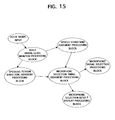
- FIG. 15 is a view illustrating the types of operation of the sound pickup apparatus.
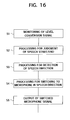
- FIG. 16 is a flowchart showing the normal processing of the sound pickup apparatus.
- the sound pickup apparatus performs processing for monitoring the sound signal in accordance with the sound pickup signals from the microphones MC1 to MC6, judges the speech start/end, judges the speech direction, and selects the microphone and displays the results on the microphone selection result displaying means 30, for example, the light emission diodes LED1 to LED6.
- Step S1 Monitoring of level conversion signal
- the signals picked up at the microphones MC1 to MC6 are converted as seven types of level data in the band-pass filter block 201 and the level conversion block 202 explained by referring to FIG. 11 to FIG. 13, especially FIG. 12, so the DSP 25 constantly monitors seven types of signals for the microphone sound pickup signals.
- the DSP 25 shifts to either processing of the speaking person direction detection processing, the speaking person direction detection processing, or the speech start end judgment processing.
- Step S2 Processing for judgment of speech start/end
- the DSP 25 judges the start and end of speech by referring to FIG. 14 and further according to the method explained in detail below.
- the DSP 25 informs the detection of the speech start to the speaking person direction judgment processing of step S4.
- the timer of the speech end judgment time (for example 0.5 second) is activated.
- the speech level is smaller than the speech end level during the speech end judgment, it is judged that the speech has ended.
- the wait processing is entered until it becomes smaller than the speech end level again.
- Step S3 Processing for detection of speaking person direction
- the processing for detection of the speaking person direction in the DSP 25 is carried out by searching for the speaking person direction constantly and continuously. Thereafter, the data is supplied to the processing for judgment of the speaking person direction of step S4.
- Step S4 Processing for switching of speaking person direction microphone
- the processing for judgment of timing in the processing for switching the speaking person direction microphone in the DSP 25 instructs the selection of a microphone in a new speaking person direction to the processing for switching the microphone signal of step S4 when the results of the processing of step S2 and the processing of step S3 are that the speaking person detection direction at that time and the speaking person direction which has been selected up to now are different.
- the selected microphone information is displayed on the microphone selection result displaying means, for example, the light emission diodes LED1 to LED6.
- Step S5 Transmission of microphone sound pickup signals
- the processing for switching the microphone signal transmits only the microphone signal selected by the processing of step S4 from among the six microphone signals as, for example, the transmission signal from the first sound pickup apparatus 10A to the second sound pickup apparatus 10B of the other party via the communication line 920, so outputs it to the line-out terminal of the communication line 920 illustrated in FIG. 5.
- Processing 1 The output levels of the sound pressure level detector corresponding to the six microphones and the threshold value of the speech start level are compared.
- the start of speech is judged when the output level exceeds the threshold value of the speech start level.
- the DSP 25 judges the signal to be from the receiving and reproduction speaker 16 and does not judge that speech has started. This is because the distances between the receiving and reproduction speaker 16 and all microphones MC1 to MC6 are the same, so the sound from the receiving and reproduction speaker 16 reaches all microphones MC1 to MC6 almost equally.
- Three sets of microphones each comprised of two single directivity microphones (microphones MC1 and MC4, microphones MC2 and MC5, and microphones MC3 and MC6) obtained by arranging the six microphones illustrated in FIG. 4 at equal angles of 60 degrees radially and at equal intervals and having directivity axes shifted by 180 degrees in opposite directions are prepared, and the level differences of microphone signals are utilized. Namely, the following operations are executed:
- the DSP 25 compares the above absolute values [1], [2], and [3] with the threshold value of the speech start level and judges the speech start when the absolute value exceeds the threshold value of the speech start level.
- FIG. 6 For the detection of the speaking person direction, the characteristic of the single directivity microphones exemplified in FIG. 6 are utilized.
- the frequency characteristic and level characteristic change according to the angle of the audio from the speaking person reaching the microphones.
- FIGS. 7A to 7D show the results of application of a fast Fourier transform (FFT) to audio picked up by microphones at constant time intervals by placing the speaker a predetermined distance from the sound pickup apparatus 10A, for example, a distance of 1.5 meters.
- FFT fast Fourier transform
- the X -axis represents the frequency
- the Y-axis represents the signal level
- the Z-axis represents time.
- the lateral lines represent the cut-off frequency of the band-pass filter.
- the level of the frequency band sandwiched by these lines becomes the data from the microphone signal level conversion processing passing through five bands of band-pass filters and converted to the sound pressure level explained by referring to FIG. 10 to FIG. 13.
- Suitable weighting processing (0 when 0 dBFs in a 1 dB full span (1 dBFs) step, while 3 when -3 dBFs, or vice versa) is carried out with respect to the output level of each band of band-pass filter. The resolution of the processing is determined by this weighting step.
- the first microphone MC1 has the smallest total points, so the DSP 25 judges that there is a sound source (there is a speaking person) in the direction of the first microphone MC1.
- the DSP 25 holds the result in the form of a sound source direction microphone number.
- the DSP 25 weights the output level of the band-pass filter of the frequency band for each microphone, ranks the outputs of the bands of band-pass filters in the sequence from the microphone signal having the smallest (largest) point up, and judges the microphone signal having the first order for three bands or more as from the microphone facing the speaking person. Then, the DSP 25 prepares the score card as in the following Table 3 indicating that there is a sound source (there is a speaking person) in the direction of the first microphone MC1.
- the result of the first microphone MC1 does not always become the top among the outputs of all band-pass filters, but if the first rank in the majority of five bands, it can be judged that there is a sound source (there is a speaking person) in the direction of the first microphone MC1.
- the DSP 25 holds the result in the form of the sound source direction microphone number.
- the DSP 25 totals up the output level data of the bands of the band-pass filters of the microphones in the form shown in the following, judges the microphone signal having a large level as from the microphone facing the speaking person, and holds the result in the form of the sound source direction microphone number.
- the DSP 25 When activated by the speech start judgment result of step S2 of FIG. 16 and detecting the microphone of a new speaking person from the detection processing result of the speaking person direction of step S3 and the past selection information, the DSP 25 issues a switch command of the microphone signal to the processing for switching selection of the microphone signal of step S5, notifies the microphone selection result displaying means (light emission diodes LED1 to 6) that the speaking person microphone was switched, and thereby informs the speaking person that the sound pickup apparatus has responded to his speech.
- the microphone selection result displaying means light emission diodes LED1 to 6
- the DSP 25 prohibits the issuance of a new microphone selection command unless the speech end judgment time (for example 0.5 second) passes after switching the microphone.
- the DSP 25 decides that speech is started after the speech end judgment time (for example 0.5 second) or more passes after all microphone signal levels (1) and microphone signal levels (2) become the speech end threshold value level or less and when any one microphone signal level (1) becomes the speech start threshold value level or more, determines the microphone facing the speaking person direction as the legitimate sound pickup microphone based on the information of the sound source direction microphone number, and starts the microphone signal selection switch processing of step S5.
- the speech end judgment time for example 0.5 second
- microphone signal levels (2) become the speech end threshold value level or less
- any one microphone signal level (1) becomes the speech start threshold value level or more determines the microphone facing the speaking person direction as the legitimate sound pickup microphone based on the information of the sound source direction microphone number, and starts the microphone signal selection switch processing of step S5.
- Second method Case where there is new speech of larger voice from another direction during period where speech is continued
- the DSP 25 starts the judgment processing after the speech end judgment time (for example 0.5 second) or more passes from the speech start (time when the microphone signal level (1) becomes the threshold value level or more).
- the DSP 25 decides there is a speaking person speaking with a larger voice than the speaking person which is selected at present at the microphone corresponding to the sound source direction microphone number, determines the sound source direction microphone as the legitimate sound pickup microphone, and activates the microphone signal selection switch processing of step S5.
- the DSP 25 is activated by the command selectively judged by the command from the switch timing judgment processing of the speaking person direction microphone of step S4 of FIG. 16.
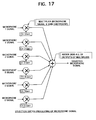
- the processing for switching the selection of the microphone signal of the DSP 25 is realized by six multipliers and a six input adder as illustrated in FIG. 17.
- the DSP 25 makes the channel gain (CH gain) of the multiplier to which the microphone signal to be selected is connected [1] and makes the CH gain of the other multipliers [0], whereby the adder adds the selected signal of (microphone signal x [1]) and the processing result of (microphone signal x [0]) and gives the desired microphone selection signal at the output.
- the change of the CH gain from [1] to [0] and [0] to [1] is made continuous for the switch transition time, for example, a time of 10 msec, to cross and thereby avoid the clicking sound due to the level difference of the microphone signals.
- the echo cancellation processing operation in the later DSP 25 can be adjusted.
- the sound pickup apparatus of the first embodiment of the present invention can be effectively applied to a call processing of a conference without the influence of noise.
- the communication apparatus of the first embodiment of the present invention has the following advantages from the viewpoint of structure:
- the communication apparatus of the first embodiment of the present invention has the following advantages from the viewpoint of the signal processing:
- a second embodiment of the present invention will be described with reference to FIGS. 19 to 21 about a detail of an echo cancellation processing.
- a sound from the other party inputted via a communication path is outputted to all directions (360 degrees) evenly from the speaker 16 of the sound pickup apparatus of this side described with reference to FIGS. 2 and 3, and can be heard by conference participants in the conference room equally.
- the sound from the speaker 16 is reflected by a wall, a ceiling and so on in the conference room of this side. That reflected sound is detected with overlapped with the sound of the conference participants of this side as an echo by a plurality of, for example, six microphones MC1 to MC6. Further, the sound from the speaker 16 may be entered to the microphones MC1 to MC6 directly, overlapped with the sound of the conference participants of this side as an echo and detected by the microphones MC1 to MC6.
- the sound detected by the microphones MC1 to MC6 may include not only a sound of the conference participants in the conference room of this side but a sound from the sound pickup apparatus of the other party.
- FIG. 19 is a fragmentary view of a sound pickup apparatus illustrating configuration of the second DSP 26 among the configuration of the sound pickup apparatus illustrated in FIG. 5 as a sound pickup apparatus of a second embodiment of the present invention.
- the second DSP 26 operates as an echo canceller performing an above-mentioned echo cancellation processing.
- the second DSP 26 performs the echo cancellation processing for each microphone. Therefore, the second DSP 26 is referred to as an echo canceller (EC) 26.
- EC echo canceller
- one EC 26 performs the echo cancellation processing for a plurality of, for example, six microphones.
- the EC 26 is realized with one DSP housing a memory, actually, it is performed a program processing in the DSP.
- the internal configuration is illustrated for a convenient or functional purpose as it is composed of an echo cancellation (EC) processing portion 261, a memory portion 263 and a control processing portion in the EC 264.
- EC echo cancellation
- the EC processing portion 261 performs an echo cancellation processing for a sound signal of the microphone inputted to the EC 26 by selected in the first DSP 25 performing a microphone selection processing and so on, and a signal after the processing is sent to the sound pickup apparatus of the other party via a D/A converter 281 and a line out terminal.
- the memory 263 stores data used in the EC processing portion 261.
- the a control processing portion in the EC 264 performs a control processing in the EC 26 such as, particularly, a timing control of the control processing in the EC processing portion 261 by cooperating with the first DSP 25.
- FIG. 20 is a block diagram showing a brief of a microphone selection processing in the first DSP 25 in the sound pickup apparatus illustrated in FIG. 19 and an echo cancellation processing in the EC 26.
- FIG. 20 An exemplification illustrated in FIG. 20 simplifies and exemplifies the case of selecting any one of two microphones MCa and MCb among six microphones illustrated in FIG. 4 in the first DSP 25.
- MCa and MCb six microphones illustrated in FIG. 4 in the first DSP 25.
- the output of two microphones MCa and MCb is inputted to the first DSP 25 via two A/D converters 27a and 27b among the A/D converters 27 illustrated in FIG. 5 and a peak is detected at peak detection portions PDa and PDb in the first DSP 25.
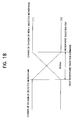
- the microphone selection processing portion 25MS in the first DSP 25 selects, for example, the one having higher peak value. As a switching method from one microphone of the microphone selection processing portion 25MS to the other microphone, it is preferable to switch it by cross-fading as illustrated in FIG. 18. Therefore, the microphone selection processing portion 25 changes values of faders FDa and FDb set in the output side of the A/D converters 27a and 27b mutually and in a crossed state.
- the sound output of two microphones MCa and MCb cross-faded via the faders FDa and FDb is added by an adder ADR and outputted to the EC 26.
- FIG. 20 A brief of the processing of the EC processing portion 261 is shown in FIG. 20.
- the EC processing portion 261 has a first switch SW1, a second switch SW2, a first and a second transmission characteristic processing portion 2611 and 2612, an adder-subtracter portion 2614 and a learning processing portion 2615.
- the first switch SW1 connects any one of off-switch, the first and the second transmission characteristic processing portions 2611 and 2612 with an output signal S1 of the A/D converter 274 by the control processing portion in the EC.
- the transmission characteristic processing portions 2611 and 2612 are portions generating echo cancellation components for signals of the microphones MCa and MCb respectively. They have the same transmission characteristic function and have a delay element and a filter coefficient different according to the microphones MCa and MCb. The transmission characteristic function, delay element and filter coefficient are described later.
- the second switch SW2 also connects any one of off-switch, the first and the second transmission characteristic processing portion 2611 and 2612 to the adder-subtracter portion 2614 by the control processing portion in the EC 264.
- Any output of connected transmission characteristic processing portions 2611 and 2612 is subtracted from a signal S25 from the adder ADR of the first DSP 25 as an echo cancellation component in the adder-subtracter portion 2614.
- the echo component is estimated in the learning processing portion 2615, the delay element and the filter coefficient according to the estimated echo component are stored (updated) in the memory portion 263 and set to any of the transmission characteristic processing portions 2611 and 2612 corresponding to any one of the microphones MCa and MCb.
- the echo cancellation processing in the EC processing portion 261 is an equalization filter processing regarding the delay element.
- the delay element is prescribed as average delay time until a microphone signal transmitted from the sound pickup apparatus of the other party is reflected by a wall, a ceiling and so on and detected by a microphone of this side, and further it reaches to the EC 26. Then, an echo signal component of amplitude that should be removed is prescribed by a filter coefficient of an equalization filter.
- the transmission characteristic processing portions 2611 and 2612 are prescribed as equalization filters prescribed by a transmission function of the same configuration, however, the delay element and the filter coefficient are different according to the microphones MCa and MCb.
- the delay element and the filter coefficient are stored in the memory portion 263 by the learning processing portion 2615.
- the learning processing portion 2615 has the transmission characteristic function equal to the transmission characteristic processing portions 2611 and 2612, inputs the output signal S1 of the A/D converter 274 showing a microphone selection signal of the sound pickup apparatus of the other party, an output signal S25 of the adder ADR in the first DSP 25 and an echo cancellation processing result signal S27 of the adder-subtracter portion 2614 continuously, learns, processes and estimates a characteristic so that an echo signal according to the microphone selection signal of the sound pickup apparatus of the other party (such as a reflection signal of the speaker 16) is removed and estimates the delay element and the filter coefficient.
- the delay element and the filter coefficient obtained by estimating in the learning processing portion 2615 are stored in the memory portion 263, configure any of the transmission characteristic processing portions 2611 and 2612 connected to the adder-subtracter portion 2614 by the switches SW1 and SW2 and equalize the output signal S1 of the A/D converter 274 in any of the transmission characteristic processing portions 2611 and 2612.
- An echo cancellation signal S26 is outputted to a D/A converter 281, where the echo cancellation signal S26 is a signal that the equalization signal is applied to the adder-subtracter portion 2614 and subtracted from the signal S25 in the adder-subtracter portion 2614 and echo signals (such as the reflection signal of the speaker 16) according to the microphone selection signal of the sound pickup apparatus of the other party are deleted.
- the echo cancellation processing is performed about the sound signal from one microphone selected among a plurality of, for example, two microphones MCa and MCb in the exemplification illustrated in FIG. 20, by one EC 26, in other words, by one EC processing portion 261.
- the switching signal is reported from the control portion 25MS in the first DSP25 or from the a whole control portion 23 via the control portion 25MS to the control processing portion in the EC 264.
- the control processing portion in the EC 264 activates the switches SW1 and SW2 so that the transmission characteristic processing portions 2611 and 2612 corresponding to the selected microphone are connected to the adder-subtracter portion 2614 and if the learning processing portion 2615 switches to the microphone that the delay element and the filter coefficient stored in the memory 23 are switched, the echo cancellation processing goes wrong.
- the echo cancellation processing will be performed about the signal of the microphones MCa and MCb switched by the echo cancellation processing signal about the microphones MCa and MCb selected previously.
- the switching of the echo cancellation processing will be performed by a method exemplified in FIG. 21.
- FIG. 21 is a view illustrated operation timing of the echo cancellation processing.
- the control processing portion in the EC 264 orders the learning processing portion 2615 of the EC processing portion 261 to stop its operation.
- the control processing portion in the EC 264 turns off the switches SW1 and SW2 and disconnects between the transmission characteristic processing portions 2611, 2612 and the adder-subtracter portion 2614.
- the echo cancellation becomes off-state, that is, the echo cancellation processing is not performed in the adder-subtracter portion 2614.
- the control portion 25MS in the first DSP 25 makes the microphones MCa and MCb to cross-fade as described in reference to FIG. 18. From the time point t4, the cross-fading begins.
- Cross-fading time ⁇ cf is tens of milliseconds usually, for example, about 10 milliseconds to 80 milliseconds.
- the control processing portion in the EC 264 reported a beginning of the cross-fading from the control portion 25MS at the time point t3 or t4 orders the learning processing portion 2615 to read out the delay element and the filter coefficient about the microphone MCb from the memory portion 263 and to set it to the switched transmission characteristic processing portion 2612.
- the learning processing portion 2615 learns the microphone MCb to be a target of a new echo cancellation processing, reads out the delay element and the filter coefficient for the microphone MCb from the memory portion 263 and set it to the corresponding transmission characteristic processing portion 2612.
- the control processing portion in the EC 264 reported finishing of cross-fading from the control portion 25MS activates the switch SW1 so that the output signal S1 of the A/D converter 274 is inputted to the transmission characteristic processing portion 2612 corresponding to the selected microphone MCb.
- an echo cancellation component is calculated by using the delay element and the filter coefficient obtained beforehand and stored in the memory portion 263 in the selected transmission characteristic processing portion 2612.
- the switch SW2 since the switch SW2 is still off in this state, the output of the transmission characteristic processing portion 2612 is not applied to the adder-subtracter portion 2614.
- the learning processing portion 2615 checks whether it reaches a state of being performed the echo cancellation processing well or not.
- the learning processing portion 2615 performs the above-mentioned check continuously. When it judges that the selected microphone MCb reaches to a state able to perform the echo cancellation processing adequately or at a certain degree, the learning processing portion 2615 begins the echo cancellation processing by applying the output signal of the transmission characteristic processing portion 2612 corresponding to the selected microphone MCb.
- time between the time point t6 and t7 is defined as echo time set beforehand, and after elapsing predetermined time from the time point t6, the above-mentioned echo cancellation processing may be restart at the time point t7.
- the echo cancellation component calculated in the transmission characteristic processing portion 2612 in the adder-subtracter portion 2614 about the microphone MCb is reduced.
- the learning processing portion 2615 estimates the echo cancellation component such that the sound signal from the sound pickup apparatus from the other party is removed in the output of the adder-subtracter 2614, learns the delay element and the filter coefficient for that, stores in the memory portion 263 and set them to the transmission characteristic processing portion 2612.
- the echo cancellation processing in the EC processing portion 261 are exemplifications.
- the other echo cancellation processing can be performed.
- an unnatural echo cancellation processing can be prevented by keeping the echo cancellation processing in an off state for predetermined time about an echo component having time constant or delay element.
- components in the DSP 26 are not limited particularly, and the above-mentioned echo cancellation processing has only to be performed in the EC 26.
- the present embodiment is particularly effective in the case of performing an echo cancellation processing by using one EC 26 (EC processing portion 261) for sound signals of a plurality of microphones.
- the delay element and the filter coefficient is set in the transmission characteristic processing portions 2611 and 2612 by using the learning processing portion 2615 and estimating the echo cancellation processing component full-time, a method without using the learning processing portion 2615 can be used.
- a transmission characteristic function is obtained for each microphone, a delay element and a filter coefficient are obtained for each microphone, they are stored in the memory portion 263 and they are used as fixed values. That is, when switching microphones, at the above-mentioned timing, for example, the control processing portion in the EC 264 sets to the transmission characteristic processing portion 2611 and 2612. According to such a method, the learning processing portion 2615 becomes unneeded, since it is not necessary to learn and to process in the learning processing portion 2615 sequentially and to estimate echo cancellation processing components, the processing of the second DSP (echo canceller) 26 is reduced.
- the second DSP echo canceller
Landscapes
- Engineering & Computer Science (AREA)
- Signal Processing (AREA)
- Health & Medical Sciences (AREA)
- Otolaryngology (AREA)
- Physics & Mathematics (AREA)
- Acoustics & Sound (AREA)
- Circuit For Audible Band Transducer (AREA)
- Telephone Function (AREA)
- Obtaining Desirable Characteristics In Audible-Bandwidth Transducers (AREA)
- Cable Transmission Systems, Equalization Of Radio And Reduction Of Echo (AREA)
Applications Claiming Priority (2)
| Application Number | Priority Date | Filing Date | Title |
|---|---|---|---|
| JP2004037264A JP4192800B2 (ja) | 2004-02-13 | 2004-02-13 | 音声集音装置と方法 |
| JP2004037264 | 2004-02-13 |
Publications (1)
| Publication Number | Publication Date |
|---|---|
| EP1564980A1 true EP1564980A1 (de) | 2005-08-17 |
Family
ID=34697933
Family Applications (1)
| Application Number | Title | Priority Date | Filing Date |
|---|---|---|---|
| EP05002907A Withdrawn EP1564980A1 (de) | 2004-02-13 | 2005-02-11 | Akustischer Echokompensator |
Country Status (6)
| Country | Link |
|---|---|
| US (1) | US20050207566A1 (de) |
| EP (1) | EP1564980A1 (de) |
| JP (1) | JP4192800B2 (de) |
| KR (1) | KR20060041853A (de) |
| CN (1) | CN1655646A (de) |
| TW (1) | TWI298984B (de) |
Cited By (3)
| Publication number | Priority date | Publication date | Assignee | Title |
|---|---|---|---|---|
| WO2010130928A1 (fr) * | 2009-05-14 | 2010-11-18 | Parrot | Procede de selection d'un microphone parmi deux microphones ou plus, pour un systeme de traitement de la parole tel qu'un dispositif telephonique "mains libres" operant dans un environnement bruite |
| US9473645B2 (en) | 2011-08-18 | 2016-10-18 | International Business Machines Corporation | Audio quality in teleconferencing |
| WO2022021633A1 (zh) * | 2020-07-31 | 2022-02-03 | 深圳市沃特沃德股份有限公司 | 远距离声音放大方法、存储介质及智能设备 |
Families Citing this family (24)
| Publication number | Priority date | Publication date | Assignee | Title |
|---|---|---|---|---|
| US8457614B2 (en) | 2005-04-07 | 2013-06-04 | Clearone Communications, Inc. | Wireless multi-unit conference phone |
| JP4965847B2 (ja) * | 2005-10-27 | 2012-07-04 | ヤマハ株式会社 | 音声信号送受信装置 |
| US8243950B2 (en) * | 2005-11-02 | 2012-08-14 | Yamaha Corporation | Teleconferencing apparatus with virtual point source production |
| US8135143B2 (en) | 2005-11-15 | 2012-03-13 | Yamaha Corporation | Remote conference apparatus and sound emitting/collecting apparatus |
| JP2007171316A (ja) * | 2005-12-20 | 2007-07-05 | Yamaha Corp | 収音装置 |
| JP4929740B2 (ja) * | 2006-01-31 | 2012-05-09 | ヤマハ株式会社 | 音声会議装置 |
| JP5070594B2 (ja) * | 2007-10-02 | 2012-11-14 | Necカシオモバイルコミュニケーションズ株式会社 | 情報処理装置、情報処理装置の音源分離方法及びプログラム |
| US8050398B1 (en) | 2007-10-31 | 2011-11-01 | Clearone Communications, Inc. | Adaptive conferencing pod sidetone compensator connecting to a telephonic device having intermittent sidetone |
| US8199927B1 (en) | 2007-10-31 | 2012-06-12 | ClearOnce Communications, Inc. | Conferencing system implementing echo cancellation and push-to-talk microphone detection using two-stage frequency filter |
| JP5034118B2 (ja) * | 2008-05-28 | 2012-09-26 | Necカシオモバイルコミュニケーションズ株式会社 | 雑音除去装置、雑音除去方法及びコンピュータプログラム |
| JP5168079B2 (ja) * | 2008-10-22 | 2013-03-21 | ヤマハ株式会社 | 音響装置 |
| JP5441541B2 (ja) * | 2009-07-22 | 2014-03-12 | 株式会社オーディオテクニカ | バウンダリーマイクロホン |
| US20110137209A1 (en) * | 2009-11-04 | 2011-06-09 | Lahiji Rosa R | Microphone arrays for listening to internal organs of the body |
| US8964966B2 (en) * | 2010-09-15 | 2015-02-24 | Avaya Inc. | Multi-microphone system to support bandpass filtering for analog-to-digital conversions at different data rates |
| KR101133308B1 (ko) * | 2011-02-14 | 2012-04-04 | 신두식 | 에코제거 기능을 갖는 마이크로폰 |
| US20130028443A1 (en) * | 2011-07-28 | 2013-01-31 | Apple Inc. | Devices with enhanced audio |
| US9538274B1 (en) | 2015-10-05 | 2017-01-03 | Hit Incorporated | Smart microphone with voice control functions |
| US10425727B2 (en) * | 2016-03-17 | 2019-09-24 | Sonova Ag | Hearing assistance system in a multi-talker acoustic network |
| KR102876428B1 (ko) * | 2016-11-08 | 2025-10-23 | 삼성전자주식회사 | 자동 음성 트리거 방법 및 이를 적용한 음향 분석기 |
| CN108198565B (zh) * | 2017-12-28 | 2020-11-17 | 深圳市东微智能科技股份有限公司 | 混音处理方法、装置、计算机设备和存储介质 |
| WO2019220768A1 (ja) | 2018-05-18 | 2019-11-21 | ソニー株式会社 | 信号処理装置、信号処理方法、プログラム |
| CN108962272A (zh) * | 2018-06-21 | 2018-12-07 | 湖南优浪语音科技有限公司 | 拾音方法和系统 |
| CN109688510B (zh) * | 2018-11-12 | 2020-05-08 | 南京南大电子智慧型服务机器人研究院有限公司 | 一种提升单指向传声器低频指向性的方法 |
| CN113409811B (zh) * | 2021-06-01 | 2023-01-20 | 歌尔股份有限公司 | 声音信号处理方法、设备和计算机可读存储介质 |
Citations (1)
| Publication number | Priority date | Publication date | Assignee | Title |
|---|---|---|---|---|
| US20020141601A1 (en) * | 2001-02-21 | 2002-10-03 | Finn Brian M. | DVE system with normalized selection |
Family Cites Families (2)
| Publication number | Priority date | Publication date | Assignee | Title |
|---|---|---|---|---|
| JP2792311B2 (ja) * | 1992-01-31 | 1998-09-03 | 日本電気株式会社 | 多チャンネルエコー除去方法および装置 |
| US7333622B2 (en) * | 2002-10-18 | 2008-02-19 | The Regents Of The University Of California | Dynamic binaural sound capture and reproduction |
-
2004
- 2004-02-13 JP JP2004037264A patent/JP4192800B2/ja not_active Expired - Fee Related
-
2005
- 2005-02-02 US US11/048,020 patent/US20050207566A1/en not_active Abandoned
- 2005-02-05 TW TW094103841A patent/TWI298984B/zh not_active IP Right Cessation
- 2005-02-07 KR KR1020050011456A patent/KR20060041853A/ko not_active Withdrawn
- 2005-02-07 CN CNA200510008206XA patent/CN1655646A/zh active Pending
- 2005-02-11 EP EP05002907A patent/EP1564980A1/de not_active Withdrawn
Patent Citations (1)
| Publication number | Priority date | Publication date | Assignee | Title |
|---|---|---|---|---|
| US20020141601A1 (en) * | 2001-02-21 | 2002-10-03 | Finn Brian M. | DVE system with normalized selection |
Non-Patent Citations (1)
| Title |
|---|
| PATENT ABSTRACTS OF JAPAN vol. 013, no. 216 (E - 760) 19 May 1989 (1989-05-19) * |
Cited By (6)
| Publication number | Priority date | Publication date | Assignee | Title |
|---|---|---|---|---|
| WO2010130928A1 (fr) * | 2009-05-14 | 2010-11-18 | Parrot | Procede de selection d'un microphone parmi deux microphones ou plus, pour un systeme de traitement de la parole tel qu'un dispositif telephonique "mains libres" operant dans un environnement bruite |
| FR2945696A1 (fr) * | 2009-05-14 | 2010-11-19 | Parrot | Procede de selection d'un microphone parmi deux microphones ou plus, pour un systeme de traitement de la parole tel qu'un dispositif telephonique "mains libres" operant dans un environnement bruite. |
| US8892433B2 (en) | 2009-05-14 | 2014-11-18 | Parrot | Method of selecting one microphone from two or more microphones, for a speech processor system such as a “hands-free” telephone device operating in a noisy environment |
| US9473645B2 (en) | 2011-08-18 | 2016-10-18 | International Business Machines Corporation | Audio quality in teleconferencing |
| US9736313B2 (en) | 2011-08-18 | 2017-08-15 | International Business Machines Corporation | Audio quality in teleconferencing |
| WO2022021633A1 (zh) * | 2020-07-31 | 2022-02-03 | 深圳市沃特沃德股份有限公司 | 远距离声音放大方法、存储介质及智能设备 |
Also Published As
| Publication number | Publication date |
|---|---|
| JP4192800B2 (ja) | 2008-12-10 |
| CN1655646A (zh) | 2005-08-17 |
| JP2005229433A (ja) | 2005-08-25 |
| TW200601865A (en) | 2006-01-01 |
| US20050207566A1 (en) | 2005-09-22 |
| TWI298984B (en) | 2008-07-11 |
| KR20060041853A (ko) | 2006-05-12 |
Similar Documents
| Publication | Publication Date | Title |
|---|---|---|
| US8238547B2 (en) | Sound pickup apparatus and echo cancellation processing method | |
| US7386109B2 (en) | Communication apparatus | |
| US20050207566A1 (en) | Sound pickup apparatus and method of the same | |
| US7227566B2 (en) | Communication apparatus and TV conference apparatus | |
| US7519175B2 (en) | Integral microphone and speaker configuration type two-way communication apparatus | |
| JP4411959B2 (ja) | 音声集音・映像撮像装置 | |
| WO2007088730A1 (ja) | 音声会議装置 | |
| JP4639639B2 (ja) | マイクロフォン信号生成方法および通話装置 | |
| JP4479227B2 (ja) | 音声集音・映像撮像装置および撮像条件決定方法 | |
| JP4281568B2 (ja) | 通話装置 | |
| JP4225129B2 (ja) | マイクロフォン・スピーカ一体構成型・双方向通話装置 | |
| JP4453294B2 (ja) | マイクロフォン・スピーカ一体構成型・通話装置 | |
| JP4269854B2 (ja) | 通話装置 | |
| GB2493801A (en) | Improved audio quality in teleconferencing system with co-located devices | |
| JP2005182140A (ja) | 飲食店の受注装置および受注方法 | |
| JP4470413B2 (ja) | マイクロフォン・スピーカ一体構成型・通話装置 | |
| JP4403370B2 (ja) | マイクロフォン・スピーカ一体構成型・通話装置 | |
| JP2005151042A (ja) | 音源位置特定装置および撮像装置並びに撮像方法 | |
| JPH0564290A (ja) | 収音装置 | |
| US20230231946A1 (en) | Device with output transducer and input transducer |
Legal Events
| Date | Code | Title | Description |
|---|---|---|---|
| PUAI | Public reference made under article 153(3) epc to a published international application that has entered the european phase |
Free format text: ORIGINAL CODE: 0009012 |
|
| AK | Designated contracting states |
Kind code of ref document: A1 Designated state(s): AT BE BG CH CY CZ DE DK EE ES FI FR GB GR HU IE IS IT LI LT LU MC NL PL PT RO SE SI SK TR |
|
| AX | Request for extension of the european patent |
Extension state: AL BA HR LV MK YU |
|
| 17P | Request for examination filed |
Effective date: 20051031 |
|
| AKX | Designation fees paid |
Designated state(s): DE FR GB |
|
| STAA | Information on the status of an ep patent application or granted ep patent |
Free format text: STATUS: THE APPLICATION HAS BEEN WITHDRAWN |
|
| 17Q | First examination report despatched |
Effective date: 20090901 |
|
| 18W | Application withdrawn |
Effective date: 20090825 |