EP1564954B1 - Sendegerät mit Bitanordnungsverfahren - Google Patents
Sendegerät mit Bitanordnungsverfahren Download PDFInfo
- Publication number
- EP1564954B1 EP1564954B1 EP20040256381 EP04256381A EP1564954B1 EP 1564954 B1 EP1564954 B1 EP 1564954B1 EP 20040256381 EP20040256381 EP 20040256381 EP 04256381 A EP04256381 A EP 04256381A EP 1564954 B1 EP1564954 B1 EP 1564954B1
- Authority
- EP
- European Patent Office
- Prior art keywords
- bit
- bits
- data
- error
- positions
- Prior art date
- Legal status (The legal status is an assumption and is not a legal conclusion. Google has not performed a legal analysis and makes no representation as to the accuracy of the status listed.)
- Expired - Lifetime
Links
Images


Classifications
-
- H—ELECTRICITY
- H04—ELECTRIC COMMUNICATION TECHNIQUE
- H04L—TRANSMISSION OF DIGITAL INFORMATION, e.g. TELEGRAPHIC COMMUNICATION
- H04L27/00—Modulated-carrier systems
- H04L27/32—Carrier systems characterised by combinations of two or more of the types covered by groups H04L27/02, H04L27/10, H04L27/18 or H04L27/26
- H04L27/34—Amplitude- and phase-modulated carrier systems, e.g. quadrature-amplitude modulated carrier systems
- H04L27/3488—Multiresolution systems
-
- H—ELECTRICITY
- H03—ELECTRONIC CIRCUITRY
- H03M—CODING; DECODING; CODE CONVERSION IN GENERAL
- H03M13/00—Coding, decoding or code conversion, for error detection or error correction; Coding theory basic assumptions; Coding bounds; Error probability evaluation methods; Channel models; Simulation or testing of codes
- H03M13/25—Error detection or forward error correction by signal space coding, i.e. adding redundancy in the signal constellation, e.g. Trellis Coded Modulation [TCM]
-
- H—ELECTRICITY
- H03—ELECTRONIC CIRCUITRY
- H03M—CODING; DECODING; CODE CONVERSION IN GENERAL
- H03M13/00—Coding, decoding or code conversion, for error detection or error correction; Coding theory basic assumptions; Coding bounds; Error probability evaluation methods; Channel models; Simulation or testing of codes
- H03M13/29—Coding, decoding or code conversion, for error detection or error correction; Coding theory basic assumptions; Coding bounds; Error probability evaluation methods; Channel models; Simulation or testing of codes combining two or more codes or code structures, e.g. product codes, generalised product codes, concatenated codes, inner and outer codes
- H03M13/2957—Turbo codes and decoding
-
- H—ELECTRICITY
- H04—ELECTRIC COMMUNICATION TECHNIQUE
- H04L—TRANSMISSION OF DIGITAL INFORMATION, e.g. TELEGRAPHIC COMMUNICATION
- H04L1/00—Arrangements for detecting or preventing errors in the information received
- H04L1/004—Arrangements for detecting or preventing errors in the information received by using forward error control
- H04L1/0041—Arrangements at the transmitter end
-
- H—ELECTRICITY
- H04—ELECTRIC COMMUNICATION TECHNIQUE
- H04L—TRANSMISSION OF DIGITAL INFORMATION, e.g. TELEGRAPHIC COMMUNICATION
- H04L1/00—Arrangements for detecting or preventing errors in the information received
- H04L1/004—Arrangements for detecting or preventing errors in the information received by using forward error control
- H04L1/0056—Systems characterized by the type of code used
- H04L1/0057—Block codes
-
- H—ELECTRICITY
- H04—ELECTRIC COMMUNICATION TECHNIQUE
- H04L—TRANSMISSION OF DIGITAL INFORMATION, e.g. TELEGRAPHIC COMMUNICATION
- H04L1/00—Arrangements for detecting or preventing errors in the information received
- H04L1/004—Arrangements for detecting or preventing errors in the information received by using forward error control
- H04L1/0056—Systems characterized by the type of code used
- H04L1/0067—Rate matching
-
- H—ELECTRICITY
- H04—ELECTRIC COMMUNICATION TECHNIQUE
- H04L—TRANSMISSION OF DIGITAL INFORMATION, e.g. TELEGRAPHIC COMMUNICATION
- H04L1/00—Arrangements for detecting or preventing errors in the information received
- H04L1/12—Arrangements for detecting or preventing errors in the information received by using return channel
- H04L1/16—Arrangements for detecting or preventing errors in the information received by using return channel in which the return channel carries supervisory signals, e.g. repetition request signals
Definitions
- the present invention relates to a transmitting apparatus that generates bit sequences so as to tend to equalize error tolerance among blocks of data that are transmitted.
- the High Speed Downlink Packet Access (HSDPA), which can provide a maximum transmission rate of about 14 Mbps in the downlink.
- the HSDPA employs an adaptive coding modulation scheme and is characterized, for example, in that the QPSK modulation scheme and the 16 QAM scheme are adaptively switched in accordance with the radio transmission environment between the base stations and mobile stations.
- the HSDPA also employs the Hybrid Automatic Repeat request (H-ARQ) scheme in which if an error is detected in the data transmitted from a base station, re-transmission is executed responding to a request from a mobile station.
- H-ARQ Hybrid Automatic Repeat request
- the main radio channels used for the HSDPA include the High Speed-Shared Control Channel (HS-SCCH), the High Speed-Physical Downlink Shared Channel (HS-PDSCH), and the High Speed-Dedicated Physical Control Channel (HS-DPCCH).
- HS-SCCH High Speed-Shared Control Channel
- HS-PDSCH High Speed-Physical Downlink Shared Channel
- HS-DPCCH High Speed-Dedicated Physical Control Channel
- the HS-SCCH and HS-PDSCH are both shared channels for a downlink (namely, in the direction from the base station to the mobile station), while HS-SCCH is the control channel for transmitting various parameters in regard to the data transmitted by the HS-PDSCH.
- HS-SCCH is the control channel for transmitting various parameters in regard to the data transmitted by the HS-PDSCH.
- information such as the modulation type, which indicates the modulation scheme used for transmission of the data with HS-PDSCH, and the number of assignments (number of codes) of the spread code, may be listed.
- the HS-DPCCH is an dedicated control channel for the uplink (namely, in the direction from the mobile station to the base station) and is used when the mobile station transmits the ACK and NACK signals to the base station in accordance with acknowledgment and noacknowledgement of reception of data received via the HS-PDSCH.
- the HS-DPCCH is also used for transmitting the result of the measurement of the reception quality (for example, the signal to interference ratio (SIR) to the base station as the Channel Quality Indicator (CQI)).
- the base station judges quality of radio environment of the downlink based on the received CQI. When the environment is good, a modulation scheme which is capable of transmitting the data at a higher transmission rate is selected. When the environment is not good, a modulation scheme which is capable of transmitting the data at a lower transmission rate is selected (namely, adaptive modulation is executed).
- Fig. 1 is a diagram illustrating a channel format in the HSDPA. Since W-CDMA employs the code division multiplexing system, each channel is separated with the spreading codes.
- CPICH Common Pilot Channel
- P-CCPCH Primary Common Control Physical Channel
- the CPICH is used for estimation of channel condition and cell search in the mobile station and as the timing reference for the other physical channel for downlink in the same cell.
- this CPICH is the channel for transmitting the pilot signal.
- the P-CCPCH is the channel for transmitting the broadcast information to the mobile stations.
- each channel forms one frame (10 ms) with 15 slots.
- the top of frames of the P-CCPCH and HS-SCCH are matched with the top of frame of the CPICH.
- the top of frame of the HS-PDSCH is delayed by two slots from the HS-SCCH or the like in order to execute the demodulation of the HS-PDSCH with the demodulation method corresponding to the received modulation type after the mobile station has received the modulation type information via the HS-SCCH.
- the HS-SCCH and HS-PDSCH form one sub-frame having three slots.
- the HS-DPCCH is used as the uplink channel, although not synchronized with the CPICH, on the basis of the timing generated by the mobile station.
- Fig. 2 illustrates a structure of a base station supporting the HSDPA.
- the reference numeral 1 designates a CRC attachment unit; 2, a code block segmentation unit; 3, a channel coding unit; 4, a bit separating unit; 5, a rate matching unit; 6, a bit collecting unit; and 7, a modulation unit.
- the transmission data transmitted via the HS-PDSCH (data stored in one sub-frame of the HS-PDSCH in Fig. 1 ) is first subjected to the CRC arithmetic process in the CRC attachment unit. Accordingly, the result of the arithmetic operations is attached to the last portion of the transmission data.
- the transmission data to which the result of CRC arithmetic operation is attached is then input to the code block segmentation unit 2 and is then segmented into a plurality of blocks. This segmentation is executed to shorten the unit data length for the error correcting coding, considering the load of decoding process on the receiving side. When the length of data has exceeded the predetermined length, the data is equally segmented into a plurality of blocks.
- An integer 2 or larger is selected as the number of segmentations and, as an example, the processes when the number of segmentations is 2 will be described here.
- the segmented transmission data are respectively processed as the object data of individual error correcting coding processes in the channel coding unit 3. Namely, the error correcting coding process is executed respectively to the segmented first block and second block.
- turbo coding is considered.
- the turbo coding system when the object data of the coding is defined as U, the data U itself, the data U' obtained by the convolutional coding of the data U and the data U" obtained by executing the interleaving on the data U and then executing the convolutional coding on the interleaved data are outputted.
- U is called the systematic bits and are the data used in both element decoders for the turbo decoding.
- This data U can be understood as the data having higher importance because of higher application frequency.
- U' and U" are called the redundant (or parity) bits and are used only one of two element decoders. These data can be understood as having a degree of importance which is lower than the data U because of lower application frequency.
- the systematic bits have a degree of importance which is higher than that of the redundant bits and a correct decoding result can be obtained with the turbo decoder if the systematic bits are received more correctly.
- the systematic bits and redundant bits generated as described above are inputted as the serial data to the bit separating unit 4.
- the bit separating unit 4 separates the input serial data into the data U, U' and U" of three systems and then outputs these data as parallel data.
- the rate matching unit 5 executes the puncturing process for deleting the bits and also executes the repetition process by repeating the bits with the predetermined algorithm in order to store the data into a sub-frame formed of three slots of the HS-PDSCH.
- bits having completed the bit adaptation process to the sub-frame in the rate matching unit 5 are then input in parallel to the bit collecting unit 6.
- the bit collecting unit 6 generates and outputs, on the basis of the input data, bit sequences of 4 bits indicating each signal point, for example, of the 16 QAM modulation.
- the modulating unit 7 outputs the signal modulated by the 16 QAM modulating method in the amplitude and phase corresponding to the signal point indicated by the input bit sequence and then sends the signal to the antenna (not illustrated) after conversion into a radio frequency signal through frequency conversion.
- Fig. 3 illustrates the arrangement method in the bit collecting unit 6.
- bits including the systematic bits, redundant bits or the like output through the rate matching process are required to correspond to the bit sequences indicating the signal points in the 16 QAM modulation. Therefore, these data must be arranged in the units of 4 bits.
- the systematic bits and redundant bits are segmented, by the code block segmentation unit, into two groups, the first block, and the second block. However, since these bits are stored in the same sub-frame, the bits are coupled again into one aggregation and processed as one data block in the bit collecting unit 6.
- bit sequences as a whole indicated as Nr(4) ⁇ N c (10) corresponds to the coupled systematic bits and redundant bits.
- the regions indicated as S1, S2, S3 and P2-1 of the first column are bit sequences corresponding to one signal point for the 16-level QAM modulation. According to Fig. 3 , since 10 bit sequences are provided, a 10 bit sequence expresses 10 signal points because 1 bit sequence expresses 1 signal point.
- the total number of systematic bits N sys of each block of two segmented blocks (the sum of the number of the first systematic bits and the number of the second systematic bits after the rate matching process) is obtained.
- the number of rows which is equal to the quotient A obtained, are defined sequentially from the top as the regions for systematic bits. Moreover, the regions in the left side of the rows of the regions occupied by the systematic bits are sequentially defined, as many as the same number as the remainder B, as the regions for systematic bits.
- the regions indicated in Fig. 3 with the oblique lines are defined as the regions for systematic bits.
- the remaining regions are defined as the regions for redundant (parity) bits.
- the systematic bits of the first block are sequentially assigned to the region defined for the systematic bits toward the bottom in the column direction from the first line, first column.
- the systematic bits region of the first column are filled, the systematic bits of the second column are filled in the same manner.
- the redundant bits are sequentially assigned from the first column to the region for the redundant bits illustrated in Fig. 3 .
- the redundant bits corresponding to U' are defined as the first redundant bits
- the redundant bits corresponding to U" are defined as the second redundant bits
- the first bit of the second redundant bits of the first block is assigned to the first column of the redundant bits region
- the first bit of the first redundant bits of the first block is assigned to the second column of the redundant bits region
- the second bit of the second redundant bits of the first block is assigned to the third column.
- the redundant bits regions are assigned by alternately assigning the second redundant bits and first redundant bits.
- the arrow marks indicate the arrangement sequence and PM-N indicates that N-th bit of the M-th redundant bits must be arranged.
- bit columns namely bit sequences, arranged as described above, indicate the signal points on the phase plane illustrated in Fig. 4 .
- the systematic bits can be understood as the important pieces of information. According to the arrangement method described above, however, tolerance to phase and amplitude variations during radio transmission is different among the blocks due to the arrangement of the systematic bits.
- Such a system may retransmit the block not generating an error because the system that cannot identify the block generating an error among a plurality of blocks is employed.
- WO 03/034640 discloses a transmission method in which systematic and parity bits are transmitted, the systematic and parity bits being mapped to different reliability positions within a symbol.
- Fig. 5 illustrates an exemplary transmitting apparatus of the present invention.
- the transmitting apparatus (radio base station) of the W-CDMA communication system corresponding to the HSDPA described previously will be described first.
- This transmitting apparatus can also be adapted to the transmitting apparatus used in the other communication system (for example UMTS).
- reference numeral 10 designates a control unit for controlling each unit (11 to 25 or the like) by sequentially outputting the transmission data (each data to be transmitted within one sub-frame) to be transmitted through the HS-DSCH.
- the HS-DSCH is the shared channel and therefore the transmit data (or transmission) to be transmitted sequentially is respectively allowed to be destined to different mobile stations.
- Numeral 11 designates a CRC attachment unit for adding a result of an arithmetic operation to the last part of the transmission data by executing the CRC arithmetic operation to the sequentially inputted transmission data (data to be transmitted within the same radio frame).
- Numeral 12 designates a bit scrambling unit for giving the randomized format to the transmission data by scrambling, in units of bits, the transmission data to which the result of the CRC arithmetic operation is attached.
- Numeral 13 designates a code block segmentation unit for segmenting (for example, substantially equally segmenting) the input transmit data after the bit scrambling if the data exceeds the predetermined data length in order to prevent, in the next channel coding, an increase in the amount of arithmetic operations of the decoder on the receiving side, which is caused when the length of the object data of coding becomes too long.
- the input data length exceeds the predetermined data length and the output is illustrated when the transmitting data is segmented into two blocks (first data block and second data block).
- the data can also be segmented into more than two blocks and can also be segmented in different data lengths rather than equal lengths.
- Numeral 14 designates a channel coding unit for individually executing the error correcting coding process on the segmented data.
- a turbo encoder is preferably used and therefore the turbo encoder is used here as an example.
- the first output includes, in regard to the first block, as described previously, the important systematic bits (U) which is the same data as the coding object data, the first redundant bits (U') obtained by convolutional coding of the systematic bits (U) and the second redundant bits (U") obtained by convolutional coding of the systematic bits after the interleaving process.
- the second output includes, in regard to the second block, the systematic bits (U), first redundant bits (U') and the second redundant bits (U").
- Numeral 15 designates a bit separation unit for separately outputting the systematic bits (U), first redundant bits (U') and second redundant bits (U") of the first block inputted in serial form from the channel coding unit 14 (turbo encoder). This process is also adapted to the second block and therefore only the output corresponding to the first block is illustrated.
- Numeral 16 designates a first rate matching unit for executing the rate matching process such as the puncturing process to store the data within a predetermined region of a buffer unit 17 in the subsequent stage.
- Numeral 17 designates a buffer unit for storing the data having completed the rate matching process in the first rate matching unit 16 into the preset region which has been set by the control unit 10 in accordance with the receiving capability of the mobile station as the data transmitting object.
- the buffer can be omitted, such as with a virtual buffer.
- Numeral 18 designates a second rate matching unit for adjusting the data length to that for storing within one sub-frame designated with the control unit 10.
- the length of the input data is adjusted to the designated length by executing the puncturing process or repetition process.
- the control unit 10 indicates the number of bits corresponding to the parameters to the second rate matching unit 18 as the data length which may be stored within one sub-frame.
- Numeral 19 designates a bit collection unit for arranging the data into a plurality of bit sequences from the second rate matching unit 19. Namely, a plurality of bit sequences are inputted in order to indicate the signal points on the phase plane by arranging the data of the first block and the data of the second block with the bit arrangement method which will be described later.
- the bit sequence is formed of four bits because the 16 QAM modulation scheme is employed. It can naturally be considered to use other multi-level modulation systems (for example, 8 PSK method or the like).
- Numeral 20 designates a physical channel segmentation unit for segmenting the bit sequences and then outputting groups of the bit sequences to the sequences of the same number as the number of spreading codes (number of codes) indicated by the control unit 10, namely for sequentially sharing and outputting, when the number of codes in the transmitting parameters is N, the input bit sequences to the sequences 1 to N.
- Numeral 21 designates an interleaving unit for respectively executing the interleaving process on the bit sequences of the N sequences.
- Numeral 22 designates a constellation re-arrangement unit for 16 QAM which can re-arrange the bits within each bit sequence for input bit sequences.
- the input bit sequence is output directly during the first transmission and bit re-arrangement can be executed at the time of re-transmission in the H-ARQ described above.
- the bit re-arrangement process for example, replaces the upper bits and the lower bits.
- the bit re-arrangement process is preferably executed equally for a plurality of bit sequences. It is also possible during re-transmission that the input bit sequence is output directly without any bit re-arrangement process.
- Numeral 23 designates a physical channel mapping unit for sharing the bit sequences of the N sequences in the subsequent stage into N spreading units included in the spreading processing unit 24.
- Numeral 24 designates a spreading processing unit which is provided with a plurality of spreading portions for outputting the corresponding I, and Q voltage values on the basis of the bit sequences of the N sequences and then also outputting the data by executing the spreading process with different spreading codes.
- bit sequences of four bits are respectively converted to respective voltage values of the I and Q elements according to Table 1.
- the upper bits sequentially correspond to I1, Q1, 12, and Q2.
- Table 1 I1, I2 I (after conversion) Q1, Q2 Q (after conversion) 0, 0 +1 0, 0 +1 0, 1 +3 0, 1 +3 1, 0 -1 1, 0 -1 1, 1 -3 1, 1 -3
- the spreading method for example, as illustrated in Fig. 6 , after the conversion in table 1 with a voltage converting unit 26, arithmetic operations are executed with a multiplier, an adder and a subtracter on the basis of the I element CI and the Q element CQ of the spreading code in order to perform the spreading process.
- numeral 25 designates a modulating unit for adding (combining) each signal spread by the spreading processing unit 24, executing the amplitude/phase modulation, for example, of the 16 QAM modulation method on the basis of the added signal and transmitting the signal to an antenna as a radio signal through frequency conversion to a radio signal.
- each bit sequence is controlled to correspond to each signal point on the phase plane, and phase/amplitude modulation is performed in accordance with each signal point.
- bit arrangement method in the bit collecting unit 19 will be described in more detail, as an example of the bit sequence generating means and arrangement method.
- Fig. 7 is illustrates the bit arrangement method in the bit collecting unit.
- the systematic bits and redundant bits output through the rate matching process by the first rate matching unit 16 and second rate matching unit 18 must be assigned to each signal point in the 16 QAM modulation. Accordingly, these bits are aligned in bit sequences of four bits. When the other amplitude/phase modulation is to be executed, four bits may be sometimes changed to a different number of bits.
- Each block segmented in the code block segmentation unit 13 is stored within the same sub-frame and therefore this block must be coupled as only one aggregation.
- An example of such aggregation is the bit matrix expressed as N r (4) ⁇ N c (10).
- the total number of bits is equal to the value corresponding to the transmission parameter notified with the control unit 10.
- the regions indicated with S1, S2, S3, P2-1 of the first column are data corresponding to only one signal point for execution of the 16 QAM modulation. According to the figure, 10 columns are provided and therefore the data for 10 signal points are illustrated.
- the regions as many as the number of lines equal to the obtained quotient A are sequentially defined as the regions for systematic bits.
- the remainder B is divided with the number of segmentation blocks 2 and a quotient B1 is obtained in order to equally assign the remainder B to the first block and second block.
- the B1 regions are sequentially defined in the row direction from the first row from the first column of the (A+1)-th row.
- the B2(B-B1) regions are sequentially defined as the regions for systematic bits in the row direction from the sixth column (the column in which the column number of the regions of the second block becomes a minimum) of the (A+1)-th row as illustrated in Fig. 7 .
- the regions indicated by the oblique lines in Fig. 7 are designated as the regions for the systematic bits and the remaining regions are designated as the regions for the redundant bits.
- the regions (redundant bit regions) other than the systematic bit regions illustrated in Fig. 7 are assigned from the first column.
- the redundant bits corresponding to the data U' are designated as the first redundant bits
- the redundant bits corresponding to the data U" are designated as the second redundant bits
- the first bit of the second redundant bits of the first block is assigned to the first column of the redundant bit regions
- the first bit of the first redundant bits of the first block is assigned next to the second column of the redundant bit regions
- the second bit of the second redundant bits of the first block is assigned next to the third column.
- the redundant bit regions are assigned by alternately assigning the second redundant bits and the first redundant bits.
- the arrow mark indicates the arrangement sequence and PM-N indicates the arrangement of the N-th bit of the M-th redundant bits.
- the input data of the first block and the input data of the second block are stored and can also be arranged to the desired position according to the read address control or the like.
- the number of systematic bits as the important bits assigned to the lower bits (here, the 3rd and 4th bits) which will easily generate an error is considered as two(2) for both first block and second block and is then equalized among the blocks. It can also be considered here that the number of systematic bits of the first and second blocks is different in several bits and is not strictly equal.
- weighting may also be executed to assign the upper bits to the side where many systematic bits are provided, considering such bit difference.
- control is executed so that an occupation rate of the predetermined bits (systematic bits, for example) included in the first data block may be set to become closer to the occupation rate of the predetermined bit (for example, systematic bits) included in the second data block in regard to the predetermined bit position within the bit column (for example, lower bits position to easily generate an error such as the 3rd bit, 4th bit).
- control is executed, according to the arrangement method in this embodiment, so that the occupation rate of the predetermined bits (for example, redundant bits) included in the first data block is set closer to the occupation rate of the predetermined bits (for example, redundant bits) included in the second data block in regard to the predetermined bit position within the bit column (for example, upper bit positions to not easily generate an error such as the 1st and 2nd bits).
- the occupation rate of the predetermined bits (for example, redundant bits) included in the first data block is set closer to the occupation rate of the predetermined bits (for example, redundant bits) included in the second data block in regard to the predetermined bit position within the bit column (for example, upper bit positions to not easily generate an error such as the 1st and 2nd bits).
- tolerances for example, tolerance of the bits of the same kind
- the bits of at least the first and second blocks are equalized, deviation in that one has a higher tolerance, while the other has a lower tolerance may be reduced and the total probability of generation of an error can be lowered.
- tolerances for the phase/amplitude variations are closed during radio transmission among the blocks for the systematic bits as the important information and it is now possible to alleviate the situation that the bits having the lower tolerance will generate an error exceeding the error correction capability thereof, although the bits having the higher tolerance may allow generation of further error with the error correcting process of the turbo code or the like.
- only one CRC check bit result of the CRC arithmetic operation which is the code for detecting the error, is attached in common to the first block and second block in order to reduce the redundant bits.
- the data of the first and second blocks is received and the CRC arithmetic operation is executed to check whether the received CRC check bits are equal to the result of the CRC arithmetic operation. Accordingly, if an error is detected, re-transmission is executed by transmission of the re-transmission request.
- ⁇ N> means the maximum integer equal to or less than N.
- A ⁇ N sys + N c >
- B ⁇ 1 ⁇ N sys - A ⁇ N c ⁇ M >
- the present embodiment discloses a bit arrangement method for the bit sequence generating apparatus, which segments the transmitting data into the two or more bit groups, including a first bit group also including the X bits, and a second group also including the Y bits, and generates the L bit sequences by arranging the bits of the first bit group, and the bits of the second bit group, to each bit position in the bit sequences of predetermined length having the first bit position and the second bit position, which generates an error more easily than the first bit position, wherein when certain bits included in the first bit group and certain bits included in the second bit group are preferably arranged at the first bit position and ⁇ N> is defined as the maximum integer equal to or less than N, the number of the certain bits included in the first bit group arranged at the second bit position is set smaller than X + Y - ⁇ X + Y ⁇ L > ⁇ L and the number of the certain bits included in the second bit group arranged to the second bit position is set equal to or larger than 1 under the conditions of ⁇ X +
- the number of the certain bits included in the first bit group arranged at the second bit position is matched with the value of (3) and the number of the certain bits included in the second bit group arranged at the second bit position becomes 0, resulting in a large difference in the error tolerance between both bit groups (among systematic bits).
- the first embodiment which is an example of the method in which the number of the certain bits included in the first bit group arranged at the second bit position is set, under the conditions of (1) and (2), smaller than the value of condition (3), and the number of the certain bits included in the second bit group arranged at the second bit position is set equal to 1 or larger, the difference in error tolerance among the first bit group and second bit group is reduced.
- a bit collection unit is provided as in this embodiment to re-arrange the data having completed the rate matching process and to generate N c bit sequences, wherein each bit sequence includes 4 bits, for 16 QAM in the radio base station corresponding to the HSDPA.
- the bit collection unit can arrange the B systematic bits up to the N c -th column from the first column for the (A+1)-th row under the condition of partially arranging the B systematic bits in a continuous manner.
- the systematic bits must be continuously arranged up to the B-th column from the first column for the (A+1)-th row like the prior art but the systematic bits can also be arranged not continuously up to the N c -th column from the first column. As a result, tolerance among the blocks can be adjusted.
- This method is characterized in a different arrangement method of the bits B of the remainder of the systematic bits, for example as described above.
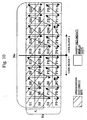
- the column in which the systematic bits are arranged is defined as 1+ ⁇ N c ⁇ (k-1) ⁇ (N sys -A ⁇ N c )>.
- k 1, 2, ..., N sys -A ⁇ N c .
- the regions indicated with the oblique lines in Fig. 10 are defined as the regions where the systematic bits are arranged, while the other regions are regions where the redundant bits are arranged.
- the arrangement sequence in each region is identical to that in the first embodiment and this description will not be repeated here.
- the tolerance for error can easily be equalized among the blocks by sequentially arranging the bits of the first and second blocks from the left side without considering the number of blocks.
- the important bits are preferably arranged to provide the lower bits having higher tolerance and the number of important bits (for example, systematic bits) to be assigned to the bits having lower tolerance among the blocks can preferably be equalized.
- the 16 QAM has been discussed as an example of the multi-level modulation system, but another multi-level modulation system, such as 8-phase PSK, can also be utilized.
- the tolerance for generation of error is sometimes graded in the three levels (first bit position, second bit position, and third bit position) in accordance with the bit position resulting from the correspondence between the bit sequence and the signal point.
- bit sequence generating means for controlling generation of the bit sequences set, for the predetermined bit position within the bit sequence, the occupation rate, for occupation of the predetermined bits included in the first data block, closer to the occupation rate, for occupation of the predetermined bits included in the second data block, determined, as the predetermined bit position, any of the first bit position, second bit position, and third bit position.
- tolerances of the bits of at least the first block and the second block are equalized, there is less deviation in the tolerances, that is, one has a higher tolerance, while the other has a lower tolerance, and therefore the total probability of generation of error can be lowered.
- the chance of an unwanted signal being transmitted by re-transmitting the blocks in the side where there is no error can be reduced through enhancement of the probability of the case where an error is generated simultaneously in both blocks or no error is generated in either block.
Landscapes
- Engineering & Computer Science (AREA)
- Computer Networks & Wireless Communication (AREA)
- Signal Processing (AREA)
- Physics & Mathematics (AREA)
- Probability & Statistics with Applications (AREA)
- Theoretical Computer Science (AREA)
- Mobile Radio Communication Systems (AREA)
- Digital Transmission Methods That Use Modulated Carrier Waves (AREA)
- Detection And Prevention Of Errors In Transmission (AREA)
- Error Detection And Correction (AREA)
Claims (17)
- Sendegerät, umfassend:eine Schaltung, die ausgelegt ist, eine Vielzahl von Bitsequenzen zu erzeugen, unter Verwendung von Bits, die in N Datenblöcken enthalten sind, miteiner Segmentierungseinheit (13), die ausgelegt ist, Daten und einen Fehlererfassungscode für die Daten in N Blöcke zu segmentieren, und einer Fehlerkorrektur-Kodiereinheit (14), die ausgelegt ist, jeweils einen Fehlerkorrektur-Kodierprozess an den N Blöcken auszuführen, wobei die Schaltung, die ausgelegt ist, eine Vielzahl von Bitsequenzen zu erzeugen, ausgelegt ist, N Blöcke systematischer Bits und redundanter Bits anzuordnen, die nach dem Fehlerkorrektur-Kodierprozess erhalten werden, in eine Vielzahl von Bitsequenzen;eine Schaltung, die ausgelegt ist zum Steuern der Vielzahl von Bitsequenzen, sodass diese mit einem Signalpunkt in der Phasenebene zusammenhängen, mit einem Anordnungsmittel (19), das ausgelegt ist, die Erzeugung der Bitsequenzen zu steuern, zum Anpassen einer Anzahl von Positionen, die durch vorbestimmte Bits belegt sind, die in den N Datenblöcken enthalten sind, sodass diese näher zueinander sind, wobei Bitpositionen gemäß einer Fehlerwahrscheinlichkeit in der jeweiligen Bitsequenz unterschieden werden, die aus dem Zusammenhang mit einem Signalpunkt auf der Phasenebene resultieren, wobei die vorbestimmten Bits die systematischen Bits sind, und das Anordnungsmittel (19) ausgelegt ist, eine Anzahl von systematischen Bits von N Blöcken auszugleichen, um in Positionen in jedem Block angeordnet zu sein, an dem ein Fehler leichter erzeugt wird; undeine Schaltung, die ausgelegt ist zum Senden der Signale, die durch Mehrfachpegel-Modulationen gemäß jedem Signalpunkt erhalten werden, wobei die Schaltung die zum Senden der Signale ausgelegt ist, eine Übertragungseinheit umfasst, die ausgelegt ist zum Senden der Daten, nach Ausführung einer Amplitudenphasen-Modulation, die mit jedem Signalpunkt in einer Phasenebene zusammenhängt, die durch jede angeordnete Bitsequenz angezeigt wird.
- Sendegerät nach Anspruch 1, wobei das Sendegerät die Signale mit einem Funkrahmen überträgt.
- Sendegerät nach Anspruch 1 oder 2, wobei jeweilige Bitsequenzen bereitgestellt werden, welche aus dem Zusammenhang mit einem Signalpunkt in der Phasenebene resultieren, wobei die Bitsequenzen erste Bitpositionen aufweisen und zweite Bitpositionen aufweisen, in denen ein Fehler leichter als in der ersten Bitposition erzeugt werden, und wobei die vorbestimmten Bitpositionen die ersten Bitpositionen oder die zweiten Bitpositionen sind.
- Sendegerät nach Anspruch 3, wobei:die Bitsequenz-Erzeugungseinheit eine Steuerung ausführt zum bevorzugten Zuweisen der systematischen Bits an die ersten Bitpositionen, gemäß der Steuerung.
- Sendegerät nach Anspruch 3, wobei die Mehrfachpegel-Modulation eine 16-QAM-Modulation ist und die ersten Bitpositionen obere Bits und die zweiten Bitpositionen untere Bits sind.
- Sendegerät nach Anspruch 5, wobei die oberen Bits ein erstes Bit und ein zweites Bit sind und die unteren Bits ein drittes Bit und ein viertes Bit sind.
- Sendegerät nach Anspruch 1, wobei:die N Datenblöcke systematische Bits enthalten, die durch eine Turbocodierung erhalten werden,die N Datenblöcke erste redundante Bits und zweite redundante Bits enthalten.
- Sendegerät nach Anspruch 1, wobei:das Anordnungsmittel (19) ferner ausgelegt ist zum im Wesentlichen sequentiellen Anordnen einer Vielzahl der Bitsequenzen bis zu derjenigen, die in den N Blöcken enthalten ist, ab derjenigen, die in dem ersten Block enthalten ist, unddas Anordnungsmittel (19) ferner ausgelegt ist zum Ausführen der Ausgleichung durch Verteilen von Bitsequenzen, die zum Anordnen der systematischen Bits in Positionen zugelassen sind, an denen ein Fehler leichter generiert wird.
- Sendegerät nach irgendeinem der Ansprüche 1 bis 7 in der Form einer Funk-Basisstation, die einen High-Speed-Downlink-Packet-Access verwendet, ferner mit:einer Kodeblock-Segmentierungseinheit (13), die ausgelegt ist zum Erzeugen von Daten durch Segmentierung, wobei die Daten N Datenblöcke enthalten, undeiner Ratenanpasseinheit (16), die ausgelegt ist zum Bereitstellen einer Ratenanpassung der Daten;wobei die Bitsequenz-Erzeugungseinheit eine Bitsammeleinheit (19) enthält, die ausgelegt ist zum Erzeugen einer 4 x NC Bit-Matrix für 16 QAM durch Umordnen der Daten von der Ratenanpasseinheit, wobei die Bitsammeleinheit kontinuierlich systematische Bits bis zu einer NC-ten Spalte von einer ersten Spalte für eine A-te Reihe von einer ersten Reihe anordnet, und auch nicht kontinuierlich B systematische Bits bis zu der NC-ten Spalte von der ersten Spalte für eine (A+1)-ten Reihe anordnet:wobei NC eine Gesamtanzahl von Spalten ist, Nsys eine Gesamtanzahl von systematischen Bits der Datenblöcke ist, <N> eine maximale ganze Zahl ist, die gleich oder geringer als N ist, A = <Nsys ÷ NC > ist, und B = Nsys - A x NC.
- Verfahren zum Senden von Daten, mit den Schritten zum:Erzeugen einer Vielzahl von Bitsequenzen unter Verwendung von Bits, die in N Datenblöcken enthalten sind; wobei Daten und ein Fehlererfassungscode für die Daten in N Blöcke segmentiert werden, und ein Fehlerkorrektur-Kodierprozess jeweils an den N Blöcken ausgeführt wird; und wobei die Vielzahl von Bitsequenzen erzeugt wird durch Anordnen von N Blöcken von systematischen Bits und redundanten Bits, die erhalten werden nach dem Fehlerkorrektur-Kodierprozess, in die Vielzahl von Bitsequenzen;Steuern der Vielzahl von Bitsequenzen, sodass diese mit einem Signalpunkt in der Phasenebene zusammenhängen, durch Steuern der Erzeugung der Bitsequenzen zum Anpassen einer Anzahl von Positionen, die durch vorbestimmte Bits besetzt werden, die in den N Datenblöcken enthalten sind, sodass diese näher zueinander sind, wobei Bitpositionen gemäß einer Fehlerwahrscheinlichkeit in der jeweiligen Bitsequenz unterschieden werden, die aus dem Zusammenhang mit einem Signalpunkt in der Phasenebene resultierend erzeugt werden; und wobei die vorbestimmten Bits die systematischen Bits sind und eine Anzahl von systematischen Bits in Positionen in jedem Block, an denen ein Fehler leichter erzeugt wird, ausgeglichen werden; undSenden der Signale, die durch Mehrfachpegel-Modulationen in Übereinstimmung mit jedem Signalpunkt erhalten werden; wobei die Daten gesendet werden nach Ausführung einer Amplitudenphasen-Modulation, die mit jedem Signalpunkt in einer Phasenebene zusammenhängen, die durch jede angeordnete Bitsequenz angezeigt wird.
- Verfahren nach Anspruch 10, wobei der Sendeschritt den Schritt umfasst zum:Senden der Signale mit in einem Funkrahmen.
- Verfahren nach Anspruch 10 oder 11, wobei die jeweiligen Bitsequenzen bereitgestellt werden, resultierend aus dem Zusammenhang mit einem Signalpunkt in der Phasenebene, wobei die Bitsequenzen erste Bitpositionen aufweisen und zweite Bitpositionen aufweisen, in denen ein Fehler leichter erzeugt wird als in den ersten Bitpositionen, und wobei die vorbestimmten Bitpositionen die ersten Bitpositionen oder die zweiten Bitpositionen sind.
- Verfahren nach Anspruch 12, wobei:der Schritt zum Steuern der Vielzahl von Bitsequenzen den Schritt umfasst zum:Ausführen einer Steuerung zum bevorzugten Zuweisen der systematischen Bits an die ersten Bitpositionen gemäß der Steuerung.
- Sendeverfahren nach Anspruch 13, wobei die Mehrfachpegel-Modulation eine 16 QAM-Modulation ist und die ersten Bitpositionen obere Bits und die zweiten Bitpositionen untere Bits sind.
- Sendeverfahren nach Anspruch 14, wobei die oberen Bits ein erstes Bit und ein zweites Bit sind und die unteren Bits ein drittes Bit und ein viertes Bit sind.
- Sendeverfahren nach Anspruch 10, wobei:die N Datenblöcke systematische Bits enthalten, die durch ein Turbocodieren erhalten werden,die N Datenblöcke erste redundante Bits und zweite redundante Bits enthalten.
- Verfahren zum Senden von Daten nach Anspruch 10, wobei das Steuern der Vielzahl von Bitsequenzen ein Bitanordnungsverfahren in einer Bitanordnungsvorrichtung umfasst, mit den Schritten zum:Erzeugen von L-Bitsequenzen durch die Schritte zum:Segmentieren von Übertragungsdaten in zwei oder mehr Bitgruppen einschließlich einer ersten Bitgruppe mit X Bits und einer zweiten Bitgruppe mit Y Bits, undAnordnen von Bits der ersten Bitgruppe und von Bits der zweiten Bitgruppe in eine erste Bitposition und eine zweite Bitposition, in der ein Fehler leichter erzeugt wird als in der ersten Bitposition,wobei bestimmte Bits in der ersten Bitgruppe und bestimmte Bits in der zweiten Bitgruppe an der ersten Bitposition angeordnet sind, eine Anzahl der bestimmten Bits, die in der ersten Bitgruppe enthalten sind, die an der zweiten Bitposition angeordnet ist, kleiner eingestellt ist als X + Y - < (X + Y) ÷ L> x L und eine Anzahl der bestimmten Bits, die in der zweiten Bitgruppe enthalten sind, die an der zweiten Bitposition angeordnet ist, auf 1 oder größer eingestellt wird, wobei

 und wobei <N> eine maximale ganze Zahl ist, die gleich oder geringer als N ist.
Priority Applications (3)
| Application Number | Priority Date | Filing Date | Title |
|---|---|---|---|
| EP10184588.1A EP2381636B1 (de) | 2004-02-12 | 2004-10-15 | Sendegerät mit Bitanordnungsverfahren |
| EP20100184417 EP2293509B1 (de) | 2004-02-12 | 2004-10-15 | Sendegerät mit Bitanordnungsverfahren |
| EP10184618.6A EP2375667B1 (de) | 2004-02-12 | 2004-10-15 | Sendegerät mit Bitanordnungsverfahren |
Applications Claiming Priority (2)
| Application Number | Priority Date | Filing Date | Title |
|---|---|---|---|
| JP2004035768A JP4539107B2 (ja) | 2004-02-12 | 2004-02-12 | 送信装置、ビット配置方法 |
| JP2004035768 | 2004-02-12 |
Related Child Applications (6)
| Application Number | Title | Priority Date | Filing Date |
|---|---|---|---|
| EP10184618.6A Division EP2375667B1 (de) | 2004-02-12 | 2004-10-15 | Sendegerät mit Bitanordnungsverfahren |
| EP20100184417 Division EP2293509B1 (de) | 2004-02-12 | 2004-10-15 | Sendegerät mit Bitanordnungsverfahren |
| EP10184588.1A Division EP2381636B1 (de) | 2004-02-12 | 2004-10-15 | Sendegerät mit Bitanordnungsverfahren |
| EP10184417.3 Division-Into | 2010-09-30 | ||
| EP10184588.1 Division-Into | 2010-09-30 | ||
| EP10184618.6 Division-Into | 2010-09-30 |
Publications (3)
| Publication Number | Publication Date |
|---|---|
| EP1564954A2 EP1564954A2 (de) | 2005-08-17 |
| EP1564954A3 EP1564954A3 (de) | 2007-09-05 |
| EP1564954B1 true EP1564954B1 (de) | 2012-01-18 |
Family
ID=34697910
Family Applications (4)
| Application Number | Title | Priority Date | Filing Date |
|---|---|---|---|
| EP10184588.1A Expired - Lifetime EP2381636B1 (de) | 2004-02-12 | 2004-10-15 | Sendegerät mit Bitanordnungsverfahren |
| EP20100184417 Expired - Lifetime EP2293509B1 (de) | 2004-02-12 | 2004-10-15 | Sendegerät mit Bitanordnungsverfahren |
| EP10184618.6A Expired - Lifetime EP2375667B1 (de) | 2004-02-12 | 2004-10-15 | Sendegerät mit Bitanordnungsverfahren |
| EP20040256381 Expired - Lifetime EP1564954B1 (de) | 2004-02-12 | 2004-10-15 | Sendegerät mit Bitanordnungsverfahren |
Family Applications Before (3)
| Application Number | Title | Priority Date | Filing Date |
|---|---|---|---|
| EP10184588.1A Expired - Lifetime EP2381636B1 (de) | 2004-02-12 | 2004-10-15 | Sendegerät mit Bitanordnungsverfahren |
| EP20100184417 Expired - Lifetime EP2293509B1 (de) | 2004-02-12 | 2004-10-15 | Sendegerät mit Bitanordnungsverfahren |
| EP10184618.6A Expired - Lifetime EP2375667B1 (de) | 2004-02-12 | 2004-10-15 | Sendegerät mit Bitanordnungsverfahren |
Country Status (4)
| Country | Link |
|---|---|
| US (5) | US7860186B2 (de) |
| EP (4) | EP2381636B1 (de) |
| JP (1) | JP4539107B2 (de) |
| CN (2) | CN101572588B (de) |
Families Citing this family (27)
| Publication number | Priority date | Publication date | Assignee | Title |
|---|---|---|---|---|
| US7773694B2 (en) | 2003-07-02 | 2010-08-10 | Panasonic Corporation | Communication apparatus and communication method |
| US7372831B2 (en) * | 2004-08-11 | 2008-05-13 | Lg Electronics Inc. | Packet transmission acknowledgement in wireless communication system |
| JP2006173867A (ja) * | 2004-12-14 | 2006-06-29 | Matsushita Electric Ind Co Ltd | 無線通信装置 |
| US7685495B2 (en) * | 2005-05-12 | 2010-03-23 | Qualcomm Incorporated | Apparatus and method for channel interleaving in communications system |
| EP1908244B1 (de) * | 2005-07-26 | 2012-04-11 | Panasonic Corporation | Bitbetriebene Umordnungs-Diversität für AICO-Abbildung |
| PT2793439T (pt) | 2005-08-05 | 2019-01-17 | Panasonic Corp | Sistema para transmitir e receber dados modulados |
| WO2007029734A1 (ja) * | 2005-09-06 | 2007-03-15 | Kddi Corporation | データ伝送システム及びデータ伝送方法 |
| EP1971098A4 (de) * | 2005-12-27 | 2012-05-02 | Fujitsu Ltd | Digitales drahtloses kommunikationsverfahren, sender und empfänger mit einem mehrebenen-modulationsschema |
| CN101346918A (zh) * | 2005-12-27 | 2009-01-14 | 松下电器产业株式会社 | 无线发送装置及多载波信号生成方法 |
| KR101225081B1 (ko) * | 2006-07-14 | 2013-01-22 | 삼성전자주식회사 | 비압축 av 데이터를 전송하기 위한 전송 패킷 구조 및이를 이용한 송수신 장치 |
| JP4675312B2 (ja) * | 2006-11-30 | 2011-04-20 | 富士通株式会社 | 符号化装置、復号装置、送信機及び受信機 |
| CN101217349A (zh) * | 2007-01-05 | 2008-07-09 | 中兴通讯股份有限公司 | 一种混合自动重传请求中比特收集的装置与方法 |
| US20080256424A1 (en) * | 2007-04-13 | 2008-10-16 | Broadcom Corporation | Information bit puncturing for turbo coding with parameter selectable rate matching tailored to lower eb/no without degrading bler (block error rate) performance |
| EP2192713B1 (de) | 2007-09-21 | 2016-03-09 | Fujitsu Limited | Übertragungsverfahren und übertragungseinrichtung |
| WO2010082280A1 (ja) * | 2009-01-15 | 2010-07-22 | パナソニック株式会社 | 無線送信装置 |
| WO2010125794A1 (ja) * | 2009-04-27 | 2010-11-04 | パナソニック株式会社 | 無線通信装置及び無線通信方法 |
| WO2010146694A1 (ja) * | 2009-06-18 | 2010-12-23 | 富士通株式会社 | 送信装置および受信装置 |
| JP5365455B2 (ja) * | 2009-09-30 | 2013-12-11 | 富士通株式会社 | レート調整装置、レート調整方法及びレート調整プログラム |
| CN101783719B (zh) * | 2010-03-18 | 2013-03-20 | 华为技术有限公司 | 一种速率匹配和解速率匹配方法、装置和通信系统 |
| JP5473866B2 (ja) * | 2010-11-08 | 2014-04-16 | 株式会社Nttドコモ | 通知方法、ユーザ端末及び無線基地局 |
| EP2629442B1 (de) * | 2012-02-14 | 2014-12-10 | Telefonaktiebolaget L M Ericsson (publ) | Auswahl der Redundanzversion anhand Empfangsqualität und Übertragungsformat |
| CN106160937B (zh) * | 2015-04-15 | 2019-01-04 | 中兴通讯股份有限公司 | 一种实现码块分割的方法及装置 |
| CA3094841C (en) | 2017-03-24 | 2023-05-02 | Zte Corporation | Processing method and device for quasi-cyclic low density parity check coding |
| KR102428522B1 (ko) | 2018-04-05 | 2022-08-03 | 삼성전자 주식회사 | 무선 통신 시스템에서 극 부호를 이용한 부호화 및 복호화를 위한 장치 및 방법 |
| JP7534763B2 (ja) * | 2020-04-08 | 2024-08-15 | 学校法人玉川学園 | 信号処理装置 |
| US12302336B2 (en) * | 2021-08-24 | 2025-05-13 | Qualcomm Incorporated | Techniques for multi-slot semi-persistent scheduling (SPS) occasions |
| CN115412210A (zh) * | 2022-08-25 | 2022-11-29 | 中交信息技术国家工程实验室有限公司 | 一种甚高频数据交换系统信息分组重发方法及系统 |
Family Cites Families (19)
| Publication number | Priority date | Publication date | Assignee | Title |
|---|---|---|---|---|
| JPH01231446A (ja) * | 1988-03-11 | 1989-09-14 | Nec Corp | Tdma回線のビット誤り率測定装置 |
| US5970098A (en) | 1997-05-02 | 1999-10-19 | Globespan Technologies, Inc. | Multilevel encoder |
| ES2275508T3 (es) * | 1999-05-19 | 2007-06-16 | Samsung Electronics Co., Ltd. | Aparato y metodo de intercalado turbo. |
| FR2800947B1 (fr) | 1999-11-04 | 2003-01-24 | Canon Kk | Procedes et dispositifs d'emission et de reception multi-porteuses, et systemes les mettant en oeuvre |
| US6476734B2 (en) * | 2000-09-14 | 2002-11-05 | Texas Instruments Incorporated | Method and apparatus for prioritizing information protection in high order modulation symbol mapping |
| JP2002171298A (ja) * | 2000-09-21 | 2002-06-14 | Matsushita Electric Ind Co Ltd | 無線送信装置及び送信信号マッピング方法 |
| CN1393089A (zh) | 2000-09-21 | 2003-01-22 | 松下电器产业株式会社 | 无线发送装置和发送信号映射方法 |
| KR100539862B1 (ko) | 2001-04-04 | 2005-12-28 | 삼성전자주식회사 | 부호분할다중접속 이동통신시스템에서 데이타 송/수신장치및 방법 |
| KR100689551B1 (ko) * | 2001-06-18 | 2007-03-09 | 삼성전자주식회사 | 부호분할다중접속 이동통신시스템에서 데이터 송신 및수신장치 및 방법 |
| WO2003039055A1 (de) | 2001-10-15 | 2003-05-08 | Siemens Aktiengesellschaft | Verfahren und vorrichtung zur abbildung der ausgangsbasis eines kodierers auf den signalraum einer qam oder psk modulation |
| US7324472B2 (en) * | 2001-10-15 | 2008-01-29 | Siemens Aktiengesellschaft | Transmission method |
| KR100474682B1 (ko) * | 2001-10-31 | 2005-03-08 | 삼성전자주식회사 | 무선통신시스템에서 패킷 재전송을 위한 송수신 장치 및 방법 |
| KR100445899B1 (ko) * | 2001-12-14 | 2004-08-25 | 한국전자통신연구원 | 터보 코드 인코더 및 그의 부호율 감소 방법 |
| KR100584426B1 (ko) * | 2001-12-21 | 2006-05-26 | 삼성전자주식회사 | 고속 패킷 이동통신시스템에서 심벌 매핑을 위한 인터리빙장치 및 방법 |
| WO2003058870A1 (de) * | 2002-01-07 | 2003-07-17 | Siemens Aktiengesellschaft | Verfahren und vorrichtung zur datenübertragung, wobei ein bitratenanpassungsmuster zwischen sender und empfänger signalisiert wird |
| JP2003223764A (ja) * | 2002-01-24 | 2003-08-08 | Fujitsu Ltd | データ再生装置 |
| GB2387515A (en) * | 2002-04-08 | 2003-10-15 | Ipwireless Inc | Mapping bits to at least two channels using two interleavers, one for systematic bits, and the other for parity bits |
| US7272191B2 (en) * | 2002-06-26 | 2007-09-18 | Nortel Networks Limited | Method and apparatus for producing and processing sequences of modulation symbols |
| US20050102600A1 (en) * | 2003-11-10 | 2005-05-12 | Anand Anandakumar | High data rate communication system for wireless applications |
-
2004
- 2004-02-12 JP JP2004035768A patent/JP4539107B2/ja not_active Expired - Lifetime
- 2004-07-27 US US10/899,068 patent/US7860186B2/en active Active
- 2004-10-15 EP EP10184588.1A patent/EP2381636B1/de not_active Expired - Lifetime
- 2004-10-15 EP EP20100184417 patent/EP2293509B1/de not_active Expired - Lifetime
- 2004-10-15 EP EP10184618.6A patent/EP2375667B1/de not_active Expired - Lifetime
- 2004-10-15 EP EP20040256381 patent/EP1564954B1/de not_active Expired - Lifetime
-
2005
- 2005-02-08 CN CN200910145463.6A patent/CN101572588B/zh not_active Expired - Fee Related
- 2005-02-08 CN CNB2005100075812A patent/CN100514900C/zh not_active Expired - Fee Related
-
2010
- 2010-07-15 US US12/836,860 patent/US7965791B2/en not_active Expired - Fee Related
- 2010-11-17 US US12/948,341 patent/US8213535B2/en not_active Expired - Fee Related
-
2011
- 2011-02-22 US US13/032,255 patent/US8085872B2/en not_active Expired - Lifetime
- 2011-02-24 US US13/033,715 patent/US8077800B2/en not_active Expired - Fee Related
Also Published As
| Publication number | Publication date |
|---|---|
| EP2375667A1 (de) | 2011-10-12 |
| EP2381636A1 (de) | 2011-10-26 |
| EP2293509A1 (de) | 2011-03-09 |
| US8213535B2 (en) | 2012-07-03 |
| CN1655491A (zh) | 2005-08-17 |
| CN101572588B (zh) | 2014-05-07 |
| EP1564954A2 (de) | 2005-08-17 |
| EP2375667B1 (de) | 2016-03-02 |
| JP4539107B2 (ja) | 2010-09-08 |
| EP2381636B1 (de) | 2016-03-02 |
| CN100514900C (zh) | 2009-07-15 |
| US20100278282A1 (en) | 2010-11-04 |
| EP1564954A3 (de) | 2007-09-05 |
| US7860186B2 (en) | 2010-12-28 |
| US20110142167A1 (en) | 2011-06-16 |
| US20050180363A1 (en) | 2005-08-18 |
| JP2005229319A (ja) | 2005-08-25 |
| US7965791B2 (en) | 2011-06-21 |
| US8085872B2 (en) | 2011-12-27 |
| US20110142168A1 (en) | 2011-06-16 |
| US8077800B2 (en) | 2011-12-13 |
| CN101572588A (zh) | 2009-11-04 |
| US20110058625A1 (en) | 2011-03-10 |
| EP2293509B1 (de) | 2012-10-10 |
Similar Documents
| Publication | Publication Date | Title |
|---|---|---|
| US7965791B2 (en) | Transmitting apparatus with bit arrangement method | |
| US7953428B2 (en) | Transmitting apparatus, receiving apparatus, and re-transmission control method | |
| KR100557167B1 (ko) | 이동통신시스템에서의 재전송 장치 및 방법 | |
| KR100827147B1 (ko) | 부호분할다중접속 이동통신시스템에서 고속 데이터의효율적 재전송 및 복호화를 위한 송,수신장치 및 방법 | |
| US7260770B2 (en) | Block puncturing for turbo code based incremental redundancy | |
| US8107444B2 (en) | Arrangement and method for channel mapping in a wireless communication system | |
| JP3657254B2 (ja) | 符号分割多重接続移動通信システムで符号化およびレートマッチング装置および方法 | |
| EP1911165B1 (de) | Verfahren zur kanalcodierung für kommunikationssysteme | |
| US20100138716A1 (en) | Method and apparatus for controlling transmitting, receiving, and re-transmission | |
| EP2323303A1 (de) | Drahtlose kommunikationsvorrichtung und drahtloskommunikationsverfahren | |
| EP2190140B1 (de) | Code-Multiplexverfahren und System für Gemeinsam genutzten Hochgeschwindigkeits-Downlink-Kanal | |
| US20050254463A1 (en) | Communication apparatus, and controlling method for re-transmission | |
| JP4569706B2 (ja) | 送信装置、ビット配置方法 |
Legal Events
| Date | Code | Title | Description |
|---|---|---|---|
| PUAI | Public reference made under article 153(3) epc to a published international application that has entered the european phase |
Free format text: ORIGINAL CODE: 0009012 |
|
| AK | Designated contracting states |
Kind code of ref document: A2 Designated state(s): AT BE BG CH CY CZ DE DK EE ES FI FR GB GR HU IE IT LI LU MC NL PL PT RO SE SI SK TR |
|
| AX | Request for extension of the european patent |
Extension state: AL HR LT LV MK |
|
| PUAL | Search report despatched |
Free format text: ORIGINAL CODE: 0009013 |
|
| AK | Designated contracting states |
Kind code of ref document: A3 Designated state(s): AT BE BG CH CY CZ DE DK EE ES FI FR GB GR HU IE IT LI LU MC NL PL PT RO SE SI SK TR |
|
| AX | Request for extension of the european patent |
Extension state: AL HR LT LV MK |
|
| 17P | Request for examination filed |
Effective date: 20071031 |
|
| 17Q | First examination report despatched |
Effective date: 20071219 |
|
| AKX | Designation fees paid |
Designated state(s): DE FR GB IT |
|
| GRAP | Despatch of communication of intention to grant a patent |
Free format text: ORIGINAL CODE: EPIDOSNIGR1 |
|
| GRAS | Grant fee paid |
Free format text: ORIGINAL CODE: EPIDOSNIGR3 |
|
| GRAA | (expected) grant |
Free format text: ORIGINAL CODE: 0009210 |
|
| AK | Designated contracting states |
Kind code of ref document: B1 Designated state(s): DE FR GB IT |
|
| REG | Reference to a national code |
Ref country code: GB Ref legal event code: FG4D |
|
| REG | Reference to a national code |
Ref country code: DE Ref legal event code: R096 Ref document number: 602004036165 Country of ref document: DE Effective date: 20120322 |
|
| PLBE | No opposition filed within time limit |
Free format text: ORIGINAL CODE: 0009261 |
|
| STAA | Information on the status of an ep patent application or granted ep patent |
Free format text: STATUS: NO OPPOSITION FILED WITHIN TIME LIMIT |
|
| 26N | No opposition filed |
Effective date: 20121019 |
|
| REG | Reference to a national code |
Ref country code: DE Ref legal event code: R097 Ref document number: 602004036165 Country of ref document: DE Effective date: 20121019 |
|
| REG | Reference to a national code |
Ref country code: FR Ref legal event code: PLFP Year of fee payment: 13 |
|
| REG | Reference to a national code |
Ref country code: FR Ref legal event code: PLFP Year of fee payment: 14 |
|
| REG | Reference to a national code |
Ref country code: FR Ref legal event code: PLFP Year of fee payment: 15 |
|
| PGFP | Annual fee paid to national office [announced via postgrant information from national office to epo] |
Ref country code: FR Payment date: 20190913 Year of fee payment: 16 |
|
| PGFP | Annual fee paid to national office [announced via postgrant information from national office to epo] |
Ref country code: DE Payment date: 20191001 Year of fee payment: 16 |
|
| PGFP | Annual fee paid to national office [announced via postgrant information from national office to epo] |
Ref country code: IT Payment date: 20191009 Year of fee payment: 16 |
|
| PGFP | Annual fee paid to national office [announced via postgrant information from national office to epo] |
Ref country code: GB Payment date: 20191010 Year of fee payment: 16 |
|
| REG | Reference to a national code |
Ref country code: DE Ref legal event code: R119 Ref document number: 602004036165 Country of ref document: DE |
|
| GBPC | Gb: european patent ceased through non-payment of renewal fee |
Effective date: 20201015 |
|
| PG25 | Lapsed in a contracting state [announced via postgrant information from national office to epo] |
Ref country code: DE Free format text: LAPSE BECAUSE OF NON-PAYMENT OF DUE FEES Effective date: 20210501 Ref country code: FR Free format text: LAPSE BECAUSE OF NON-PAYMENT OF DUE FEES Effective date: 20201031 |
|
| PG25 | Lapsed in a contracting state [announced via postgrant information from national office to epo] |
Ref country code: GB Free format text: LAPSE BECAUSE OF NON-PAYMENT OF DUE FEES Effective date: 20201015 |
|
| PG25 | Lapsed in a contracting state [announced via postgrant information from national office to epo] |
Ref country code: IT Free format text: LAPSE BECAUSE OF NON-PAYMENT OF DUE FEES Effective date: 20201015 |