EP1564822A2 - Vorrichtung und Regelverfahren für die Erzeugung elektrischer Energie - Google Patents
Vorrichtung und Regelverfahren für die Erzeugung elektrischer Energie Download PDFInfo
- Publication number
- EP1564822A2 EP1564822A2 EP05001050A EP05001050A EP1564822A2 EP 1564822 A2 EP1564822 A2 EP 1564822A2 EP 05001050 A EP05001050 A EP 05001050A EP 05001050 A EP05001050 A EP 05001050A EP 1564822 A2 EP1564822 A2 EP 1564822A2
- Authority
- EP
- European Patent Office
- Prior art keywords
- electric current
- electric power
- value
- electric
- thermoelectric element
- Prior art date
- Legal status (The legal status is an assumption and is not a legal conclusion. Google has not performed a legal analysis and makes no representation as to the accuracy of the status listed.)
- Granted
Links
Images


Classifications
-
- H—ELECTRICITY
- H10—SEMICONDUCTOR DEVICES; ELECTRIC SOLID-STATE DEVICES NOT OTHERWISE PROVIDED FOR
- H10N—ELECTRIC SOLID-STATE DEVICES NOT OTHERWISE PROVIDED FOR
- H10N10/00—Thermoelectric devices comprising a junction of dissimilar materials, i.e. devices exhibiting Seebeck or Peltier effects
-
- F—MECHANICAL ENGINEERING; LIGHTING; HEATING; WEAPONS; BLASTING
- F01—MACHINES OR ENGINES IN GENERAL; ENGINE PLANTS IN GENERAL; STEAM ENGINES
- F01N—GAS-FLOW SILENCERS OR EXHAUST APPARATUS FOR MACHINES OR ENGINES IN GENERAL; GAS-FLOW SILENCERS OR EXHAUST APPARATUS FOR INTERNAL-COMBUSTION ENGINES
- F01N5/00—Exhaust or silencing apparatus combined or associated with devices profiting by exhaust energy
- F01N5/02—Exhaust or silencing apparatus combined or associated with devices profiting by exhaust energy the devices using heat
- F01N5/025—Exhaust or silencing apparatus combined or associated with devices profiting by exhaust energy the devices using heat the device being thermoelectric generators
-
- Y—GENERAL TAGGING OF NEW TECHNOLOGICAL DEVELOPMENTS; GENERAL TAGGING OF CROSS-SECTIONAL TECHNOLOGIES SPANNING OVER SEVERAL SECTIONS OF THE IPC; TECHNICAL SUBJECTS COVERED BY FORMER USPC CROSS-REFERENCE ART COLLECTIONS [XRACs] AND DIGESTS
- Y02—TECHNOLOGIES OR APPLICATIONS FOR MITIGATION OR ADAPTATION AGAINST CLIMATE CHANGE
- Y02T—CLIMATE CHANGE MITIGATION TECHNOLOGIES RELATED TO TRANSPORTATION
- Y02T10/00—Road transport of goods or passengers
- Y02T10/10—Internal combustion engine [ICE] based vehicles
- Y02T10/12—Improving ICE efficiencies
Definitions
- the invention relates to an electric power generating apparatus using a thermoelectric element. More particularly, the invention relates to control of generated electric power in an electric power converter in an electric power generating apparatus which is provided in an exhaust system of an automobile or the like, and which supplies electric power generated due to a temperature difference between exhaust gas and a cooling medium, using the electric power converter.
- thermoelectric power generating apparatus which recovers, as electric power, heat energy contained in exhaust gas discharged from a combustion device such as an engine of an automobile.
- a thermoelectric power generating apparatus one end of a thermoelectric element is heated by exhaust gas, and the other end of the thermoelectric element is cooled by a cooling medium such as coolant, whereby electric power is generated in the thermoelectric element due to a temperature difference between the exhaust gas and the cooling medium.
- a cooling medium such as coolant
- thermoelectric element varies depending on an electric current value when the output electric power is obtained. Further, this electric current - electric power (voltage) characteristic varies also depending on a temperature at each of both ends of the thermoelectric element. Accordingly, as disclosed in Japanese Patent Application Publication No. JP-A-6-22572, in order to efficiently obtain electric power when a condition on a high-temperature side of the thermoelectric element and a condition on a low-temperature side of the thermoelectric element change, for example, when electric power is generated using exhaust gas of an automobile, it is necessary to control electric current when the electric power is obtained according to the electric current-electric power (voltage) characteristic.
- thermoelectric element a temperature on the high-temperature side of the thermoelectric element and a temperature on the low-temperature side of the thermoelectric element are measured; an electric current value at which the output electric power becomes optimal is obtained based on an output characteristic of the thermoelectric element at the measured temperatures, the output characteristic being obtained in advance; and the electric current is controlled to become equal to the obtained electric current value when the electric power is obtained.
- thermoelectric element In order to closely attach temperature sensors on the high-temperature side and the low temperature side of the thermoelectric element, a fixing member such as a spacer is required.
- the fixing member and the temperature sensors serve as thermal resistance.
- the amount of heat transmitted in the thermoelectric element is decreased, and electric power generation efficiency is also reduced.
- multiple thermoelectric elements are connected in order to increase the amount of generated electric power.
- temperatures at both ends of the thermoelectric element vary with each thermoelectric element, it is difficult to detect overall tendency in the - temperatures using the small number of temperature sensors. Meanwhile, if the number of the temperature sensors is increased, cost is increased, and the electric power generation efficiency is reduced. Therefore, increasing the number of the temperature sensors is also difficult.
- in order to accurately detect a transient change in the temperatures it is necessary to enhance responsiveness of the temperature sensors. Particularly when responsiveness of the temperature sensor on the high-temperature side is enhanced, the cost is increased.
- thermoelectric element which makes it possible to efficiently obtain electric power without requiring temperature measurement.
- a first aspect of the invention relates to an electric power generating apparatus including a thermoelectric element; and an electric power converter which controls electric current when the thermoelectric element generates electric power.
- the electric power converter changes the electric current when the thermoelectric element generates the electric power so as to obtain at least two different electric current values i 1 and i 2 , and one of voltage values and electric power values corresponding to the at least two different electric current values i 1 and i 2 , the electric current value i 1 being smaller than the electric current value i 2 ;
- the electric power converter obtains an electric current value at which maximum electric power can be obtained in electric current - electric power characteristic that is defined based on the at least two electric current values i 1 and i 2 , and one of the voltage values and the electric power values corresponding to the at least two electric current values i 1 and i 2 ; and the electric power converter controls the electric current such that a value of the electric current becomes equal to the electric current value at which the maximum electric power can be obtained when the thermoelectric element generates the electric power.
- a second aspect of the invention relates to an electric power generating apparatus including a thermoelectric element; and an electric power converter which controls electric current when the thermoelectric element generates electric power.
- thermoelectric element An electric current (i) - voltage (V) characteristic of the thermoelectric element varies depending on a temperature on a high-temperature side of the thermoelectric element and a temperature on a low-temperature side of the thermoelectric element.
- the values of V 0 and k vary depending on the temperature on the high-temperature side of the thermoelectric element and the temperature on the low-temperature side of the thermoelectric element. Refer to FIG. 3).
- the electric power converter may include an ammeter that measures a value of electric current flowing in the thermoelectric element, and a voltmeter that measures a value of voltage between output terminals of the thermoelectric element.
- the thermoelectric element may include a high-temperature side end surface and a low-temperature side end surface, and may generate the electric power according to a temperature difference between the high-temperature side end surface and the low-temperature side end surface.
- the high-temperature side end surface may be provided in a vicinity of an exhaust passage of an automobile, and a cooling device may be provided on the low-temperature side end surface.
- a third aspect of the invention relates to an electric power generating apparatus including a thermoelectric element; and an electric power converter which controls electric current when the thermoelectric element generates electric power.
- the electric power converter changes the electric current when the thermoelectric element generates the electric power to obtain electric power values W 1 and W 2 corresponding to at least two different electric current values i 1 and i 2 , the electric current value i 1 being smaller than the electric current value i 2 ;
- the electric power converter estimates an electric current - electric power characteristic based on a combination of the electric current value i 1 and the obtained electric power value W, and a combination of the electric current value i 2 and the obtained electric power value W 2 ;
- the electric power converter obtains an electric current value at which maximum electric power can be obtained using the electric current - electric power characteristic; and the electric power converter controls the electric current such that a value of the electric current becomes equal to the electric current value at which the maximum electric power can be obtained when the thermoelectric element generates the electric power.
- the electric current - voltage characteristic is obtained based on the combination of the electric current i 1 and the obtained electric power value W, and the combination of the electric current i 2 and the obtained electric power value W 2 , and the electric current value i t is obtained using this electric current - voltage characteristic. More specifically, the electric current value i t may be obtained after the values of k and V 0 are obtained, or the electric current value i t may be stored in a storage device.
- the electric power converter may obtain one of a voltage value and an electric power value corresponding to an electric current value i 3 , the electric current value i 3 being different from the electric current values i 1 and i 2 , and the electric power converter may select the electric current - electric power characteristic from among the estimated plural electric current - electric power characteristics based on a combination of the electric current value i 3 and one of the voltage value and the electric power value corresponding to the electric current value i 3 .
- the electric current - electric power characteristic varies depending on the two constant values V 0 and k. Therefore, when two combinations of the electric current value and the voltage value are obtained, the values of V 0 and k should be determined, and the electric current - electric power characteristic should be determined. However, since there is a limit to the accuracy of detecting the electric current value and the electric power value, the accuracy cannot be made higher than necessary. In the case where plural electric current - electric power characteristics are estimated when considering an error of each detected value or a change in the accuracy, another combination of the electric current value and the voltage value or the electric power value is obtained, and the electric current - electric power characteristic is selected from among the plural estimated electric current - electric power characteristics.
- the electric current value and the voltage value or the electric power value are measured, and it is not necessary to provide an additional sensor in the thermoelectric module including the thermoelectric element. Therefore, heat resistance is not changed, and electric power generation efficiency is not reduced. Also, it is possible to accurately measure the electric current value, the voltage value, the electric power value, and the like using relatively low-cost sensors. Also, the responsiveness of these sensors is good. Accordingly, it is possible to promptly obtain the optimal electric current value at which the maximum electric power can be obtained. Also, it is possible to appropriately perform the electric current control even when there is a transient change in an engine operating state.
- these sensors can be included in the electric power converter. In this case, it is easy to assemble the electric power generating apparatus, and the manufacturing cost thereof can be reduced.
- the electric power converter may obtain one of a voltage value and an electric power value corresponding to an electric current value i 3 , the electric current value i 3 being different from the electric current values i 1 and i 2 , and the electric power converter may select the electric current - electric power characteristic from among the estimated plural electric current - electric power characteristics based on a combination of the electric current value i 3 and one of the voltage value and the electric power value corresponding to the electric current value i 3 .
- the electric power converter may include an ammeter that measures a value of electric current flowing in the thermoelectric element, and a voltmeter that measures a value of voltage between output terminals of the thermoelectric element.
- the electric power converter may include an ammeter that measures a value of electric current flowing in the thermoelectric element, and a wattmeter that measures a value of electric power output from the thermoelectric element.
- the thermoelectric element may include a high-temperature side end surface and a low-temperature side end surface, and may generate the electric power according to a temperature difference between the high-temperature side end surface and the low-temperature side end surface.
- the high-temperature side end surface may be provided in a vicinity of an exhaust passage of an automobile, and a cooling device may be provided on the low-temperature side end surface.
- a fourth aspect of the invention relates to a control method for an electric power generating apparatus including a thermoelectric element; and an electric power converter which controls electric current when the thermoelectric element generates electric power.
- the control method includes the steps of changing the electric current when the thermoelectric element generates the electric power so as to obtain at least two different electric current values i 1 and i 2 , and one of voltage values and electric power values corresponding to the at least two different electric current values i 1 and i 2 , the electric current value i 1 being smaller than the electric current value i 2 ; and, obtaining an electric current value at which maximum electric power can be obtained in electric current - electric power characteristic that is defined based on the at least two electric current values i 1 and i 2 , and one of the voltage values and the electric power values corresponding to the at least two electric current values i 1 and i 2 ; and the electric power converter controls the electric current such that a value of the electric current becomes equal to the electric current value at which the maximum electric power can be obtained when the thermoelectric element generates
- a fifth aspect of the invention relates to a control method for an electric power generating apparatus including a thermoelectric element; and an electric power converter which controls electric current when the thermoelectric element generates electric power.
- a sixth aspect of the invention relates to a control method for an electric power generating apparatus including a thermoelectric element; and an electric power converter which controls electric current when the thermoelectric element generates electric power.
- the control method includes the steps of changing the electric current when the thermoelectric element generates the electric power so as to obtain electric power values W 1 and W 2 corresponding to at least two different electric current values i 1 and i 2 , the electric current value i 1 being smaller than the electric current value i 2 ; and estimating an electric current - electric power characteristic based on a combination of the electric current value i 1 and the obtained electric power value W, and a combination of the electric current value i 2 and the obtained electric power value W 2 , obtaining an electric current value at which maximum electric power can be obtained using the electric current - electric power characteristic, and controlling the electric current such that a value of the electric current becomes equal to the electric current value at which the maximum electric power can be obtained when the thermoelectric element generates the electric power.
- FIG. 1 is a schematic diagram showing a configuration of an electric power generating apparatus according to the invention.
- An electric power generating apparatus 1 is provided in an exhaust system of an automobile.
- the electric power generating apparatus 1 includes a thermoelectric module 2 which is formed by connecting multiple thermoelectric elements 20, and an electric power converter 3.
- the thermoelectric element 20 is formed by connecting multiple p-type semiconductors and n-type semiconductors in a ⁇ shape.
- a high-temperature end side of the thermoelectric module 2 is fixed, through an insulating member 50, to an outer side of an exhaust pipe 4 in which exhaust gas flows.
- a low-temperature end side of the thermoelectric module 2 is connected, through an insulating member 51, to a cooling case 6 in which coolant flows.
- Both of the insulating members 50, 51 are insulators having good heat conduction. Both of the insulating members 50, 51 may be made of the same material. However, since the temperature of the insulating member 50 becomes high, at least the insulating member 50 needs to have good heat resistance.
- the electric power converter 3 houses an ammeter 30 for measuring an electric current value i that is the value of electric current flowing in the thermoelectric module 2, and a voltmeter 31 for measuring a voltage value V that is the value of voltage between output terminals.
- the electric power converter 3 includes a control portion 32 for performing electric current control, therein.
- the electric power converter 3 has a function of a DC-DC converter, and is connected to a battery 7.
- the control portion 32 includes a ROM, a RAM, a CPU, and the like.
- a heat sink 41 that is configured to have a fin shape is provided so that heat of exhaust gas can be efficiently transmitted to the thermoelectric module 2.
- the heat sink 41 is heated by exhaust gas flowing in the exhaust pipe 4, and the temperature of the exhaust gas becomes high.
- a high-temperature side end surface of each thermoelectric element 20 is heated due to heat transmitted from the heat sink 41 through the insulating member 50.
- heat of a low-temperature side end surface is removed by the coolant flowing in the cooling case 6 due to heat transmission through the insulating member 51.
- the temperature of the high-temperature side end surface and the temperature of the low-temperature side end surface become different from each other. Electric current flows in the thermoelectric element 20 due to a Seebeck effect caused by the temperature difference, and electric power is obtained.
- FIG. 3 is a graph showing an electric current (i) - voltage (V) characteristic of the thermoelectric module 2, and an electric current (i) - electric power (W) characteristic of the thermoelectric module 2.
- a solid line shows a case where the temperature of the high-temperature side end surface is Th1, and the temperature of the low-temperature side end surface is Tc1.
- a dashed line shows a case where the temperature of the high-temperature side end surface is Th2, and the temperature of the low-temperature side end surface is Tc2.
- the relationship among these temperatures is represented by an equation, (Th1 - Tc1) > (Th2 > Tc2).
- the electric current (i) - voltage (V) characteristic of the thermoelectric element varies depending on the temperatures of both the end surfaces.
- the electric current (i) - voltage (V) characteristic of the thermoelectric element depends on the temperature difference between both the end surfaces.
- the relationship between the electric current i and the voltage V is represented by an equation (1) described below when the temperatures of both the end surfaces are given temperatures.
- V V 0 -k ⁇ i (1) 0 ⁇ i ⁇ V 0 /k
- V 0 i>V 0 /k
- V 0 and k are constant values.
- the value of V 0 and the value of k are different from each other. That is, the values of V 0 and k depend on the temperature of the high-temperature side end surface and the temperature of the low-temperature side end surface. Since output electric power W that can be obtained is represented by an equation, i ⁇ V, the output electric power in the case of "0 ⁇ i ⁇ V 0 / k" is represented by an equation (2) described below.
- the electric power converter 3 controls the electric current flowing in the thermoelectric module 2 such that a value of the electric current becomes equal to the electric current value i t when the electric power is obtained, the electric power can be obtained most efficiently.
- the electric power generating apparatus controls the electric current such that the value of the electric current becomes equal to the electric current value i t when the electric power is obtained, without using a temperature sensor.
- FIG. 4 is a flowchart showing an electric current control process in a first control mode.
- FIG. 5 is a graph explaining a method of calculating the electric current value i t in the electric current control process in the first control mode.
- the electric current control process is performed by the control portion 32 of the electric power converter 3.
- step S1 the value of electric current is changed to an electric current value i 1 and an electric current value i 2 with reference to the result of measurement performed by the ammeter 30 when the electric power is obtained from the thermoelectric module 2.
- the relationship between the electric current values i 1 and i 2 is represented by an equation, i 1 ⁇ i 2 . That is, the electric current value i 1 is smaller than the electric current value i 2 .
- the electric current value i 2 should be substantially equal to a value obtained by an equation, 2 ⁇ i 1 .
- a voltage value V 1 corresponding to the electric current value i 1 , and a voltage value V 2 corresponding to the electric current value i 2 are detected, using the voltage meter 31.
- the electric power converter 3 can instantly change the value of electric current supplied to the thermoelectric module 2. Therefore, two combinations of the electric current value and the voltage value can be detected in an extremely short time. That is, the speed at which the two combinations of the electric current value and the voltage value can be detected is extremely high, as compared to the speed at which the temperatures of the high-temperature side end surface and the low-temperature side end surface change. Accordingly, the changes in the temperatures before and after the electric current value is changed are negligible.
- the optimal electric current value i 1 is calculated (step S2).
- the electric current (i) - voltage (V) characteristic can be shown by one straight line. Since the combination of the electric current i 1 and the voltage value V 1 (i 1 , V 1 ) and the combination of the electric current i 2 and the voltage value V 2 (i 2 , V 2 ) are shown by two points on this straight line, the values of V 0 and k in the equation (1) can be calculated using these two points, as follows.
- V 0 (i 2 V 1 - i 1 V 2 ) / (i 2 - i 1 )
- k (V 1 - V 2 ) / (i 2 - i 1 )
- the optimal electric current value i t can be calculated according to the equation (3).
- the optimal electric current value i t may be directly obtained based on the combinations of the electric current value and the voltage value (i 1 , V 1 ) and (i 2 , V 2 ), according to an equation (6) described below, without calculating the values of V 0 and k separately.
- i t (i 2 V 1 -i 1 V 2 )/ ⁇ 2 ⁇ (V 1 -V 2 ) ⁇
- the optimal electric current value i t may be calculated by reading out, from a map stored in the electric power converter 3, the optimal electric current value i t corresponding to the combinations of the electric current value and the voltage value, (i 1 V 1 ) and (i 2 , V 2 ).
- the obtained optimal electric current value i t matches the optimal electric current value i t represented by the equation (6), and is included in the scope of the invention.
- step S3 the electric power generation state of the thermoelectric module 2 is controlled such that the electric current value becomes equal to the optimal electric current value i t , with reference to the output of the ammeter 30.
- thermoelectric power generation can be performed at the optimal electric current value without using an temperature sensor, heat energy of the exhaust gas can be efficiently converted to electric energy, and the electric energy can be recovered.
- the temperatures and the flow amounts of the coolant and exhaust gas change, or in the case where a sufficient time has not elapsed since the engine is started, and therefore the temperature of the thermoelectric module 2 itself is low and the temperature of the high-temperature side end surface has not been sufficiently increased, the temperatures of the high-temperature side end surface and the low-temperature side end surface also change. Therefore, it is preferable that the optimal electric current value i t should be determined considering a transient change in an engine operating state.
- the process of setting the optimal electric current value i t shown in FIG. 4 is performed at predetermined timing.
- the process of setting the optimal electric current value i t may be always performed at constant time intervals, or the time intervals at which the process of setting the optimal electric current value i t is repeatedly performed may be variable. For example, it may be determined whether an engine operating state is a steady state or a transient state based on a signal from an engine ECU (not shown) for controlling the engine, and when the engine operating state is the transient state, the time intervals at which the setting process is performed may be made short, as compared to when the engine operating state is the steady state.
- the time intervals at which the setting process is performed may be made short, and when the optimal electric current value i t changes by a small amount, the time intervals may be made long.
- thermoelectric module since the optimal operation of the thermoelectric module can be performed using a simple configuration, the electric power can be efficiently generated. Also, since it is easy to maintain a good heat transmission state between the thermoelectric module and the heat source (i.e., exhaust gas and the coolant), the electric power generation efficiency can be improved. Also, an existing electric power generating apparatus can be performed with higher efficiency by providing the electric power converter 3.
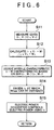
- FIG. 6 is a flowchart showing the electric current control process in the second control mode.
- FIG. 7 is a graph explaining a method of calculating the optimal electric current value i t in this electric current control process in the second control mode.
- This electric current control process is performed by the control portion 32 of the electric power converter 3, as in the case of the electric current control process in the first control mode.
- step S11 the value of the electric current is changed to the electric current value i 1 and the electric current value i 2 with reference to the result of measurement performed by the ammeter 30 when the electric power is obtained from the thermoelectric module 2.
- the relationship between the electric current values i 1 and i 2 is represented by an equation, i 1 ⁇ i 2 . That is, the electric current value i 1 is smaller than the electric current value i 2 .
- the relationship between the electric current values i 1 and i 2 should be represented by an equation, i 2 ⁇ 2 ⁇ i 1 .
- the voltage value V 1 corresponding to the electric current value i 1 , and the voltage value V 2 corresponding to the electric current value i 2 are detected, using the voltage meter 31.
- an electric power amount W in the case where the electric current value is i 1 and the voltage value is V 1 , and an electric power amount W 2 in the case where the electric current value is i 2 and the voltage value is V 2 are calculated (step S12).
- the optimal electric current value i t can be obtained according to the equation (3) (step S 14).
- the optimal electric current value i t may be calculated by reading out, from a map stored in the electric power converter 3, the values of V 0 and k corresponding to the combinations of the electric current value and the electric power value (i 1 , W 1 ) and (i 2 , W 2 ), instead of calculating the values of V 0 and k using the equations (7) and (8).
- step S15 the electric power generation state of the thermoelectric module 2 is controlled such that the electric current value becomes equal to the optimal electric current value i t' with reference to the output of the ammeter 30.
- the electric power amount is obtained based on the electric current value and the voltage value.
- an electric power value may be obtained by providing a wattmeter instead of the voltmeter 31 shown in FIG. 1.
- the electric power value may be obtained based on the amount of electric power supplied to the battery 7.
- each of the output values of the ammeter, the voltmeter, and the wattmeter has an error.
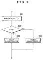
- FIG. 9 is a flowchart showing part of this control process. This control process is inserted between step S 13 and step S 14 of the control process shown in FIG. 6.
- step S 13 characteristic lines A and B shown in FIG. 8 are decided as candidates for the electric current (i) - electric power (W) characteristic line. Further, in step S21, the electric current value is changed to a value obtained by 2 ⁇ i 2 , with reference to the result of measurement performed by the ammeter 30. The voltage value V3 at this time is obtained.
- step S22 the voltage value V3 and 0 are compared to each other.
- the characteristic line B is selected (step S23).
- the characteristic line A is selected (step S22).
- the voltage value corresponding to the electric current value 2 ⁇ i 2 is additionally obtained.
- the electric power value corresponding to the electric current value 2 ⁇ i 2 may be obtained.
- the electric current value when the voltage value or the electric power value is additionally obtained is not limited to the value obtained by 2 ⁇ i 2 .
- One of the two electric current values may be made a candidate for the optimal electric current value, or an electric current value k ⁇ i 2 (it is preferable that the value of k should be larger than 1, and should be equal to or smaller than 2) may be used.
- thermoelectric power generating apparatus provided in an exhaust system of an automobile.
- the invention is not limited to this.
- the invention can be applied to, for example, a thermoelectric power generating apparatus which converts heat energy of combustion gas of various types of internal combustion engines or combustion devices, or heat energy of drain warm water to electric energy and recovers the electric energy.
Landscapes
- Engineering & Computer Science (AREA)
- Chemical & Material Sciences (AREA)
- Combustion & Propulsion (AREA)
- Mechanical Engineering (AREA)
- General Engineering & Computer Science (AREA)
- Control Of Temperature (AREA)
- Measurement Of Current Or Voltage (AREA)
- Control Of Eletrric Generators (AREA)
- Inverter Devices (AREA)
- Control Of Electrical Variables (AREA)
Applications Claiming Priority (2)
| Application Number | Priority Date | Filing Date | Title |
|---|---|---|---|
| JP2004040407A JP4123163B2 (ja) | 2004-02-17 | 2004-02-17 | 発電装置 |
| JP2004040407 | 2004-02-17 |
Publications (3)
| Publication Number | Publication Date |
|---|---|
| EP1564822A2 true EP1564822A2 (de) | 2005-08-17 |
| EP1564822A3 EP1564822A3 (de) | 2009-05-20 |
| EP1564822B1 EP1564822B1 (de) | 2012-01-04 |
Family
ID=34697997
Family Applications (1)
| Application Number | Title | Priority Date | Filing Date |
|---|---|---|---|
| EP05001050A Expired - Lifetime EP1564822B1 (de) | 2004-02-17 | 2005-01-19 | Vorrichtung und Regelverfahren für die Erzeugung elektrischer Energie |
Country Status (4)
| Country | Link |
|---|---|
| US (1) | US7667132B2 (de) |
| EP (1) | EP1564822B1 (de) |
| JP (1) | JP4123163B2 (de) |
| CN (1) | CN100533943C (de) |
Cited By (4)
| Publication number | Priority date | Publication date | Assignee | Title |
|---|---|---|---|---|
| DE102009053214A1 (de) * | 2009-11-06 | 2011-05-12 | Benteler Automobiltechnik Gmbh | Thermosensor an einem thermoelektrischen Generator und Verfahren zur Regelung des Gesamtwiderstands eines thermoelektrischen Generators |
| EP2362456A1 (de) * | 2010-02-25 | 2011-08-31 | Koninklijke Philips Electronics N.V. | Thermoelektrogeneratorsystem |
| EP2381072A1 (de) * | 2010-04-22 | 2011-10-26 | IFP Energies nouvelles | Nach einem Rankine-Zyklus arbeitender geschlossener Kühlmittelkreislauf und Verfahren zum Benutzen eines solchen Kreislaufes |
| US8937402B2 (en) | 2009-05-14 | 2015-01-20 | Commissariat A L'energie Atomique Et Aux Energies Alternatives | Converter circuit and electronic system comprising such a circuit |
Families Citing this family (14)
| Publication number | Priority date | Publication date | Assignee | Title |
|---|---|---|---|---|
| US20120227684A1 (en) * | 2008-12-25 | 2012-09-13 | Industrial Technology Research Institute | Hydrogen/oxygen gas generating apparatus and internal combustion engine system having the same |
| WO2010151803A1 (en) * | 2009-06-25 | 2010-12-29 | Kalkanoglu Husnu M | Roofing products, photovoltaic roofing elements and systems using them |
| CN101795077B (zh) * | 2010-04-12 | 2013-01-23 | Bcd半导体制造有限公司 | 一种控制变换器输出电流电压特性曲线的装置 |
| DE102010044803A1 (de) | 2010-09-09 | 2012-03-15 | Emitec Gesellschaft Für Emissionstechnologie Mbh | Thermoelektrisches Modul für einen thermoelektrischen Generator eines Fahrzeugs mit einem Dichtelement |
| US20130228205A1 (en) * | 2011-01-25 | 2013-09-05 | Yury Vernikovskiy | Apparatus for reversibly converting thermal energy to electric energy |
| JP6131525B2 (ja) * | 2012-03-29 | 2017-05-24 | いすゞ自動車株式会社 | 熱電変換素子の制御装置 |
| TWI480565B (zh) * | 2013-06-27 | 2015-04-11 | China Steel Corp | Simulation System of Thermoelectric Power Generation Performance |
| JP6155982B2 (ja) * | 2013-08-30 | 2017-07-05 | コニカミノルタ株式会社 | 電力制御装置、および画像形成装置 |
| JP6267562B2 (ja) * | 2014-03-26 | 2018-01-24 | 株式会社Kelk | 熱電発電装置及び熱電発電方法 |
| KR20160063000A (ko) * | 2014-11-26 | 2016-06-03 | 현대자동차주식회사 | 열전 발전장치 |
| CN104410141A (zh) * | 2014-12-03 | 2015-03-11 | 中山大学 | 一种对发热体降温并回收发热体能源的方法 |
| KR102542945B1 (ko) * | 2018-04-24 | 2023-06-15 | 현대자동차주식회사 | 차량용 열교환장치 |
| US20220250087A1 (en) * | 2018-10-22 | 2022-08-11 | Shanghai Bixiufu Enterprise Management Co., Ltd. | Engine exhaust dust removing system and method |
| US11996790B2 (en) | 2019-08-20 | 2024-05-28 | Calagen, Inc. | Producing electrical energy using an etalon |
Family Cites Families (7)
| Publication number | Priority date | Publication date | Assignee | Title |
|---|---|---|---|---|
| JPS61254082A (ja) * | 1985-04-30 | 1986-11-11 | Suzuki Motor Co Ltd | 排気熱発電装置 |
| JPS63262075A (ja) * | 1987-04-20 | 1988-10-28 | Nippon Steel Corp | 排気熱熱電変換発電器 |
| JPH0622572A (ja) * | 1992-06-30 | 1994-01-28 | Aqueous Res:Kk | 熱電発電充電装置 |
| US6150601A (en) * | 1998-04-28 | 2000-11-21 | Halliburton Energy Services, Inc. | Method and apparatus for generating electric power downhole |
| JP4057805B2 (ja) * | 2001-11-29 | 2008-03-05 | サンデン株式会社 | 可変容量圧縮機の制御装置 |
| US20030223919A1 (en) * | 2002-05-30 | 2003-12-04 | Sehoon Kwak | Integrated thermoelectric power generator and catalytic converter |
| AU2003294155A1 (en) | 2002-12-26 | 2004-07-22 | Toyota Jidosha Kabushiki Kaisha | Exhaust heat power generation apparatus |
-
2004
- 2004-02-17 JP JP2004040407A patent/JP4123163B2/ja not_active Expired - Fee Related
-
2005
- 2005-01-19 EP EP05001050A patent/EP1564822B1/de not_active Expired - Lifetime
- 2005-02-04 US US11/049,685 patent/US7667132B2/en not_active Expired - Fee Related
- 2005-02-17 CN CNB2005100083607A patent/CN100533943C/zh not_active Expired - Fee Related
Non-Patent Citations (1)
| Title |
|---|
| None |
Cited By (7)
| Publication number | Priority date | Publication date | Assignee | Title |
|---|---|---|---|---|
| US8937402B2 (en) | 2009-05-14 | 2015-01-20 | Commissariat A L'energie Atomique Et Aux Energies Alternatives | Converter circuit and electronic system comprising such a circuit |
| DE102009053214A1 (de) * | 2009-11-06 | 2011-05-12 | Benteler Automobiltechnik Gmbh | Thermosensor an einem thermoelektrischen Generator und Verfahren zur Regelung des Gesamtwiderstands eines thermoelektrischen Generators |
| EP2362456A1 (de) * | 2010-02-25 | 2011-08-31 | Koninklijke Philips Electronics N.V. | Thermoelektrogeneratorsystem |
| WO2011104645A3 (en) * | 2010-02-25 | 2012-02-16 | Koninklijke Philips Electronics N.V. | Thermo-electric generator system |
| RU2549909C2 (ru) * | 2010-02-25 | 2015-05-10 | Конинклейке Филипс Электроникс Н.В. | Система термоэлектрического генератора |
| EP2381072A1 (de) * | 2010-04-22 | 2011-10-26 | IFP Energies nouvelles | Nach einem Rankine-Zyklus arbeitender geschlossener Kühlmittelkreislauf und Verfahren zum Benutzen eines solchen Kreislaufes |
| FR2959272A1 (fr) * | 2010-04-22 | 2011-10-28 | Inst Francais Du Petrole | Circuit ferme fonctionnant selon un cycle de rankine et procede utilisant un tel circuit |
Also Published As
| Publication number | Publication date |
|---|---|
| US20050178425A1 (en) | 2005-08-18 |
| EP1564822A3 (de) | 2009-05-20 |
| JP2005237058A (ja) | 2005-09-02 |
| CN1658488A (zh) | 2005-08-24 |
| CN100533943C (zh) | 2009-08-26 |
| JP4123163B2 (ja) | 2008-07-23 |
| US7667132B2 (en) | 2010-02-23 |
| EP1564822B1 (de) | 2012-01-04 |
Similar Documents
| Publication | Publication Date | Title |
|---|---|---|
| US7667132B2 (en) | Electric power generating apparatus and control method for electric power generating apparatus | |
| US11215657B2 (en) | Real-time online prediction method for dynamic junction temperature of semiconductor power device | |
| CN103988358B (zh) | 具有带有外部的和集成的温度传感器的蓄电池单池的蓄电池和用于使蓄电池运行的方法 | |
| US10454011B2 (en) | Malfunction detection device for power generator | |
| CN103105412A (zh) | 用于确定二组分混合物中气体浓度的气体传感器和方法 | |
| Barako et al. | A reliability study with infrared imaging of thermoelectric modules under thermal cycling | |
| JP2005117835A (ja) | 熱電発電システムの温度検出装置 | |
| JP6754382B2 (ja) | 熱電発電装置 | |
| CN115249941A (zh) | 一种半导体激光器的温度控制系统和方法 | |
| CN103003674B (zh) | 用于确定在废气物料流量传感器上得到的总物料流量的方法 | |
| Sandu et al. | Experimental investigation of thermoelectric heat recovery from a diesel engine | |
| He et al. | An in-depth study of nonlinear parametric characterization for thermoelectric generator modules | |
| CN116615858A (zh) | 功率控制装置、热电发电系统以及功率控制方法 | |
| Omkar et al. | Air conditioning system in car using thermoelectric effect | |
| JP4715326B2 (ja) | 熱電発電装置 | |
| Costa et al. | Autonomous wireless sensor with a low cost TEG for application in automobile vehicles | |
| KR101848012B1 (ko) | 열전 반도체의 열전도도 및 열전 성능지수 측정방법 | |
| JP4474550B2 (ja) | 熱電素子の特性評価方法 | |
| Raja et al. | Electro-thermal peltier cooling system for internal combustion engine waste heat recovery | |
| US20140287519A1 (en) | Method, Control Device and Device for Analyzing a Gas | |
| JP7550955B2 (ja) | 熱電変換制御装置および熱電変換装置の制御方法 | |
| Karlsson | Powering sensors through Energy Harvesting from Water Pipes with a Peltier Module | |
| JP2005127162A (ja) | 排熱回収装置 | |
| Siouane et al. | Identification of thermal resistances of thermoelectric modules by electrical characterization | |
| Sharma et al. | Experimental Investigation on Thermoelectric Generator used for Exhaust Gas of a Four Stroke SI Engine |
Legal Events
| Date | Code | Title | Description |
|---|---|---|---|
| PUAI | Public reference made under article 153(3) epc to a published international application that has entered the european phase |
Free format text: ORIGINAL CODE: 0009012 |
|
| 17P | Request for examination filed |
Effective date: 20050217 |
|
| AK | Designated contracting states |
Kind code of ref document: A2 Designated state(s): AT BE BG CH CY CZ DE DK EE ES FI FR GB GR HU IE IS IT LI LT LU MC NL PL PT RO SE SI SK TR |
|
| AX | Request for extension of the european patent |
Extension state: AL BA HR LV MK YU |
|
| PUAL | Search report despatched |
Free format text: ORIGINAL CODE: 0009013 |
|
| AK | Designated contracting states |
Kind code of ref document: A3 Designated state(s): AT BE BG CH CY CZ DE DK EE ES FI FR GB GR HU IE IS IT LI LT LU MC NL PL PT RO SE SI SK TR |
|
| AX | Request for extension of the european patent |
Extension state: AL BA HR LV MK YU |
|
| AKX | Designation fees paid |
Designated state(s): DE FR GB |
|
| 17Q | First examination report despatched |
Effective date: 20100429 |
|
| GRAP | Despatch of communication of intention to grant a patent |
Free format text: ORIGINAL CODE: EPIDOSNIGR1 |
|
| GRAS | Grant fee paid |
Free format text: ORIGINAL CODE: EPIDOSNIGR3 |
|
| GRAA | (expected) grant |
Free format text: ORIGINAL CODE: 0009210 |
|
| AK | Designated contracting states |
Kind code of ref document: B1 Designated state(s): DE FR GB |
|
| REG | Reference to a national code |
Ref country code: GB Ref legal event code: FG4D |
|
| RIN1 | Information on inventor provided before grant (corrected) |
Inventor name: ITOH, YUJI Inventor name: MURATA, KIYOHITO |
|
| REG | Reference to a national code |
Ref country code: DE Ref legal event code: R096 Ref document number: 602005031943 Country of ref document: DE Effective date: 20120301 |
|
| REG | Reference to a national code |
Ref country code: GB Ref legal event code: 746 Effective date: 20121012 |
|
| PLBE | No opposition filed within time limit |
Free format text: ORIGINAL CODE: 0009261 |
|
| STAA | Information on the status of an ep patent application or granted ep patent |
Free format text: STATUS: NO OPPOSITION FILED WITHIN TIME LIMIT |
|
| REG | Reference to a national code |
Ref country code: DE Ref legal event code: R084 Ref document number: 602005031943 Country of ref document: DE Effective date: 20121015 |
|
| 26N | No opposition filed |
Effective date: 20121005 |
|
| REG | Reference to a national code |
Ref country code: DE Ref legal event code: R097 Ref document number: 602005031943 Country of ref document: DE Effective date: 20121005 |
|
| REG | Reference to a national code |
Ref country code: FR Ref legal event code: PLFP Year of fee payment: 12 |
|
| REG | Reference to a national code |
Ref country code: FR Ref legal event code: PLFP Year of fee payment: 13 |
|
| PGFP | Annual fee paid to national office [announced via postgrant information from national office to epo] |
Ref country code: FR Payment date: 20161215 Year of fee payment: 13 |
|
| PGFP | Annual fee paid to national office [announced via postgrant information from national office to epo] |
Ref country code: DE Payment date: 20170110 Year of fee payment: 13 |
|
| PGFP | Annual fee paid to national office [announced via postgrant information from national office to epo] |
Ref country code: GB Payment date: 20170118 Year of fee payment: 13 |
|
| REG | Reference to a national code |
Ref country code: DE Ref legal event code: R119 Ref document number: 602005031943 Country of ref document: DE |
|
| GBPC | Gb: european patent ceased through non-payment of renewal fee |
Effective date: 20180119 |
|
| PG25 | Lapsed in a contracting state [announced via postgrant information from national office to epo] |
Ref country code: FR Free format text: LAPSE BECAUSE OF NON-PAYMENT OF DUE FEES Effective date: 20180131 Ref country code: DE Free format text: LAPSE BECAUSE OF NON-PAYMENT OF DUE FEES Effective date: 20180801 |
|
| REG | Reference to a national code |
Ref country code: FR Ref legal event code: ST Effective date: 20180928 |
|
| PG25 | Lapsed in a contracting state [announced via postgrant information from national office to epo] |
Ref country code: GB Free format text: LAPSE BECAUSE OF NON-PAYMENT OF DUE FEES Effective date: 20180119 |