EP1564731A2 - Appareil de lecture optique et élément optique diffractif pour appareil de lecture optique - Google Patents
Appareil de lecture optique et élément optique diffractif pour appareil de lecture optique Download PDFInfo
- Publication number
- EP1564731A2 EP1564731A2 EP05250762A EP05250762A EP1564731A2 EP 1564731 A2 EP1564731 A2 EP 1564731A2 EP 05250762 A EP05250762 A EP 05250762A EP 05250762 A EP05250762 A EP 05250762A EP 1564731 A2 EP1564731 A2 EP 1564731A2
- Authority
- EP
- European Patent Office
- Prior art keywords
- optical
- area
- diffractive
- light
- light flux
- Prior art date
- Legal status (The legal status is an assumption and is not a legal conclusion. Google has not performed a legal analysis and makes no representation as to the accuracy of the status listed.)
- Withdrawn
Links
Images


Classifications
-
- B—PERFORMING OPERATIONS; TRANSPORTING
- B29—WORKING OF PLASTICS; WORKING OF SUBSTANCES IN A PLASTIC STATE IN GENERAL
- B29C—SHAPING OR JOINING OF PLASTICS; SHAPING OF MATERIAL IN A PLASTIC STATE, NOT OTHERWISE PROVIDED FOR; AFTER-TREATMENT OF THE SHAPED PRODUCTS, e.g. REPAIRING
- B29C53/00—Shaping by bending, folding, twisting, straightening or flattening; Apparatus therefor
- B29C53/56—Winding and joining, e.g. winding spirally
- B29C53/58—Winding and joining, e.g. winding spirally helically
-
- G—PHYSICS
- G11—INFORMATION STORAGE
- G11B—INFORMATION STORAGE BASED ON RELATIVE MOVEMENT BETWEEN RECORD CARRIER AND TRANSDUCER
- G11B7/00—Recording or reproducing by optical means, e.g. recording using a thermal beam of optical radiation by modifying optical properties or the physical structure, reproducing using an optical beam at lower power by sensing optical properties; Record carriers therefor
- G11B7/12—Heads, e.g. forming of the optical beam spot or modulation of the optical beam
- G11B7/135—Means for guiding the beam from the source to the record carrier or from the record carrier to the detector
- G11B7/1353—Diffractive elements, e.g. holograms or gratings
-
- B—PERFORMING OPERATIONS; TRANSPORTING
- B29—WORKING OF PLASTICS; WORKING OF SUBSTANCES IN A PLASTIC STATE IN GENERAL
- B29C—SHAPING OR JOINING OF PLASTICS; SHAPING OF MATERIAL IN A PLASTIC STATE, NOT OTHERWISE PROVIDED FOR; AFTER-TREATMENT OF THE SHAPED PRODUCTS, e.g. REPAIRING
- B29C53/00—Shaping by bending, folding, twisting, straightening or flattening; Apparatus therefor
- B29C53/56—Winding and joining, e.g. winding spirally
- B29C53/566—Winding and joining, e.g. winding spirally for making tubular articles followed by compression
-
- B—PERFORMING OPERATIONS; TRANSPORTING
- B29—WORKING OF PLASTICS; WORKING OF SUBSTANCES IN A PLASTIC STATE IN GENERAL
- B29C—SHAPING OR JOINING OF PLASTICS; SHAPING OF MATERIAL IN A PLASTIC STATE, NOT OTHERWISE PROVIDED FOR; AFTER-TREATMENT OF THE SHAPED PRODUCTS, e.g. REPAIRING
- B29C53/00—Shaping by bending, folding, twisting, straightening or flattening; Apparatus therefor
- B29C53/80—Component parts, details or accessories; Auxiliary operations
- B29C53/8008—Component parts, details or accessories; Auxiliary operations specially adapted for winding and joining
- B29C53/8016—Storing, feeding or applying winding materials, e.g. reels, thread guides, tensioners
-
- B—PERFORMING OPERATIONS; TRANSPORTING
- B29—WORKING OF PLASTICS; WORKING OF SUBSTANCES IN A PLASTIC STATE IN GENERAL
- B29C—SHAPING OR JOINING OF PLASTICS; SHAPING OF MATERIAL IN A PLASTIC STATE, NOT OTHERWISE PROVIDED FOR; AFTER-TREATMENT OF THE SHAPED PRODUCTS, e.g. REPAIRING
- B29C53/00—Shaping by bending, folding, twisting, straightening or flattening; Apparatus therefor
- B29C53/80—Component parts, details or accessories; Auxiliary operations
- B29C53/8008—Component parts, details or accessories; Auxiliary operations specially adapted for winding and joining
- B29C53/8083—Improving bonding of wound materials or layers
-
- G—PHYSICS
- G11—INFORMATION STORAGE
- G11B—INFORMATION STORAGE BASED ON RELATIVE MOVEMENT BETWEEN RECORD CARRIER AND TRANSDUCER
- G11B7/00—Recording or reproducing by optical means, e.g. recording using a thermal beam of optical radiation by modifying optical properties or the physical structure, reproducing using an optical beam at lower power by sensing optical properties; Record carriers therefor
- G11B7/12—Heads, e.g. forming of the optical beam spot or modulation of the optical beam
- G11B7/125—Optical beam sources therefor, e.g. laser control circuitry specially adapted for optical storage devices; Modulators, e.g. means for controlling the size or intensity of optical spots or optical traces
- G11B7/127—Lasers; Multiple laser arrays
- G11B7/1275—Two or more lasers having different wavelengths
-
- B—PERFORMING OPERATIONS; TRANSPORTING
- B29—WORKING OF PLASTICS; WORKING OF SUBSTANCES IN A PLASTIC STATE IN GENERAL
- B29C—SHAPING OR JOINING OF PLASTICS; SHAPING OF MATERIAL IN A PLASTIC STATE, NOT OTHERWISE PROVIDED FOR; AFTER-TREATMENT OF THE SHAPED PRODUCTS, e.g. REPAIRING
- B29C53/00—Shaping by bending, folding, twisting, straightening or flattening; Apparatus therefor
- B29C53/80—Component parts, details or accessories; Auxiliary operations
- B29C53/8008—Component parts, details or accessories; Auxiliary operations specially adapted for winding and joining
- B29C53/8016—Storing, feeding or applying winding materials, e.g. reels, thread guides, tensioners
- B29C2053/8025—Storing, feeding or applying winding materials, e.g. reels, thread guides, tensioners tensioning
-
- B—PERFORMING OPERATIONS; TRANSPORTING
- B29—WORKING OF PLASTICS; WORKING OF SUBSTANCES IN A PLASTIC STATE IN GENERAL
- B29L—INDEXING SCHEME ASSOCIATED WITH SUBCLASS B29C, RELATING TO PARTICULAR ARTICLES
- B29L2023/00—Tubular articles
- B29L2023/22—Tubes or pipes, i.e. rigid
-
- G—PHYSICS
- G11—INFORMATION STORAGE
- G11B—INFORMATION STORAGE BASED ON RELATIVE MOVEMENT BETWEEN RECORD CARRIER AND TRANSDUCER
- G11B7/00—Recording or reproducing by optical means, e.g. recording using a thermal beam of optical radiation by modifying optical properties or the physical structure, reproducing using an optical beam at lower power by sensing optical properties; Record carriers therefor
- G11B2007/0003—Recording, reproducing or erasing systems characterised by the structure or type of the carrier
- G11B2007/0006—Recording, reproducing or erasing systems characterised by the structure or type of the carrier adapted for scanning different types of carrier, e.g. CD & DVD
Definitions
- the present invention relates to an optical pickup apparatus and a diffractive optical element.
- a wavelength of a laser light source used as a light source for reproducing of information recorded on an optical disc and for recording of information on an optical disc has been made shorter in a field of an optical pickup apparatus, and for example, there have been put to practical use laser light sources each having a wavelength of 405 nm such as a violet semiconductor laser and a violet SHG laser that conducts a wavelength conversion of an infrared semiconductor laser by utilizing second harmonic generation.
- violet light sources when using an objective lens having the same numerical aperture (NA) as in DVD (digital versatile disc), it is possible to record information of 15 - 20 GB for the optical disc with a diameter of 12 cm, and when NA of the objective lens is raised up to 0.85, it is possible to record information of 23 - 25 GB for the optical disc with a diameter of 12 cm.
- NA numerical aperture
- optical discs and magneto-optical discs employing the violet laser light source are generically called "a high density optical disc”.
- the aperture regulating means there are known, for example, a method to intercept a ray of light mechanically by using a diaphragm, a method to use a dichroic filter having a wavelength selectivity concerning the transmittance of the ray of light, a method to use a phase control element based on a liquid crystal and a method to combine the foregoing (for example, see Patent Document 1)
- Patent Document 1 discloses an optical pickup apparatus that is provided separately with an optical element wherein a hologram is formed on an area (central area) that is in a form of concentric circles each having its center on an optical axis, and a diffraction grating is formed on a circumference of the central area (peripheral area) and with an objective lens of a refraction type.
- a light flux with wavelength 635 nm for DVD is transmitted and a light flux with wavelength 780 nm for CD is diffracted in the central area, while, a light flux with wavelength 635 nm is transmitted and a light flux with wavelength 780 nm is substantially intercepted through diffraction in the peripheral area.
- Patent Document 1 is one wherein a light flux among two types light fluxes each having a different wavelength is diffracted by a hologram optical element, and another light flux is transmitted and is converged on an optical disc through the objective lens.
- a wavelength (near 780 nm) of a light flux used for recording and reproducing for CD is about twice a wavelength (near 400 nm) of a light flux used for recording and reproducing for the high density optical disc, thus, it is difficult to design a diffractive structure capable of giving an optimum diffracting actions to both the light flux for the high density optical disc and the light flux for CD, which is a problem. Due to the necessity to solve the aforementioned problems, it is difficult to use the technology disclosed in the aforesaid Patent Document as it is as a technology to realize compatibility for three types of optical discs.
- the dichroic filter Even in the case of using the dichroic filter, it is difficult to form a thin layer that.can regulate an aperture properly for three types of light fluxes each having a different wavelength, and the cost is increased, which is a problem.
- an object of the invention is to provide an optical pickup apparatus equipped with an optical element that can regulate a aperture properly for three types of discs including a high density optical disc employing a violet laser light source, DVD and CD.
- optical pickup apparatus PU1 relating to the invention is provided with a diffractive optical element arranged in the common optical path for the first - third light fluxes, an optical surface of the diffractive optical element is divided into first - third areas, and the second area and the third area are provided respectively with the first diffractive structure and the second diffractive structure.
- Each of the first - third light fluxes having passed through the first area forms a converged spot on an information recording surface of each prescribed optical disc
- the first light source and the second light source having passed through the second area also form converged spots respectively
- the third light flux having passed the second area does not form a converged spot, thus, either one of the first light flux and the second light flux having passed the third area forms a converged spot, and none of another light flux and the third light flux having passed the third area forms a converged spot.
- a high density optical disc which also includes an optical disc (for example, HD DVD, hereafter HD) complying a standard that a thickness of a protective layer is about 0.6 mm and conducts recording and reproducing of information with an objective optical system having NA of 0.65 - 0.67, in addition to an optical disc (for example, a Blu Ray disc, hereafter BD) complying a standard that a thickness of a protective layer is about 0.1 mm and conducts recording and reproducing of information with an objective optical system having NA of 0.85.
- an optical disc for example, a Blu Ray disc, hereafter BD
- the high density optical disc includes also a magneto-optical disc using a violet semiconductor laser and a violet SHG laser as a light source for recording and reproducing of information.
- DVD is a generic name for optical discs of DVD series such as DVD-ROM, DVD-Video, DVD-Audio, DVD-RAM, DVD-R, DVD-RW, DVD+R and DVD+RW
- CD is a generic name for optical discs of CD series such as CD-ROM, CD-Audio, CD-Video, CD-R and CD-RW.
- an objective optical system means an optical system that is arranged at the position facing an optical disc in an optical pickup apparatus and includes at least a light converging element having functions to converge light fluxes each being emitted from a light source and having a different wavelength on each of information recording surfaces of optical discs each having a different recording density.
- the objective optical system may also be composed only of a light converging element.
- an optical element including the optical element and the light converging element is the objective optical system.
- An optical pickup apparatus comprises a first light source emitting a first light flux with wavelength ⁇ 1, a second light source emitting a second light flux with wavelength ⁇ 2 ( ⁇ 2 > ⁇ 1), a third light source emitting a third light flux with wavelength ⁇ 3 ( ⁇ 3 > ⁇ 2) and an objective optical system having a light converging element for converging the first light flux, the second light flux and the third light flux respectively on an information recording surface of a first optical disk with protective substrate thickness tl, an information recording surface of a second optical disk with protective substrate thickness t2 (t2 ⁇ t1) and an information recording surface of a third optical disk with protective substrate thickness t3 (t3 > t2).
- a diffractive optical element is provided in of the optical pickup apparatus, the diffractive optical element is arranged in the common optical path for the first - third light fluxes, and an optical surface of the diffractive optical element includes a first area that is in a form of a concentric circle having its center on an optical axis and includes the optical axis, a second area that is in a form of a concentric circle having its center on the optical axis and is formed to be outside the first area and is provided with a first diffractive structure, and a third area that is in a form of a concentric circle having its center on the optical axis and is formed to be outside the first area and is provided with a second diffractive structure.
- the first - third light fluxes having passed through the first area and the light converging element form converged spots respectively on information recording surfaces of the prescribed optical discs
- the first and second light fluxes having passed through the second area and the light converging element form converged spots respectively on information recording surfaces of the prescribed optical discs
- the third light flux having passed through the second area and the light converging element does not form a converged spot on an information recording surface of the third light disk
- either one of the first light flux and the second light flux having passed through the third area and the light converging element forms a converged spot on an information recording surface of the prescribed optical disc
- another light flux and the third light flux having passed through the third area and the light converging element do not form converged spots on information recording surfaces of the prescribed optical discs.
- the diffractive structure is formed by one optical element. Furthermore, it is preferable that the second and third areas are formed on the one optical surface of the optical element, or the second area is formed on the one optical surface of the optical element and the third area is formed on the opposite optical surface of the optical element.
- the second and third areas are formed on one optical element as above, it can save time and efforts of assembling and alignment, and space for the optical element, compared with the second and third areas formed on several optical elements.
- the first diffractive structure provides a diffractive action to the third light flux passing through the second area
- the second diffractive structure provides a diffractive action another of the first light flux and the second light flux passing through the third area.
- the optical pickup device prefferably has aperture regulating functions concerning the third light flux, by forming a first diffractive structure on the second area, by providing a second diffractive structure on the third area, and by giving diffracting actions to the third light flux passing through the first and second diffractive structures to make flare component that does not contribute to spot formation on an information recording surface of the third optical disk, as described above.
- the optical pickup device it is possible to make the optical pickup device to have aperture regulating functions concerning the second light flux, by giving diffracting actions to the second light flux passing through the second diffractive structure to make flare component that does not contribute to spot formation on an information recording surface of the second optical disk.
- the optical pickup device having compatibility for three types of optical discs, it is not necessary to use a dichroic filter or a liquid crystal phase control element, for example, and it is possible to restrain the manufacturing cost of the optical pickup device.
- the first diffractive structure is organized by forming the ring-shaped zones in a form of concentric circles each having its center on an optical axis having therein a stairs-structure (step-structure) formed by step portions and discontinuous portions in the prescribed quantity, and is established not to give a phase difference substantially to the first and second light fluxes passing through the second area
- the second diffractive structure is organized by forming the ring-shaped zones in a form of concentric circles each having its center on an optical axis having therein a stairs-structure (step-structure) formed by step portions and discontinuous portions in the prescribed quantity, and is established not to give a phase difference substantially to another light flux passing through the third area.
- n1 represents the refractive index of the diffractive optical element for the wavelength ⁇ 1
- d1 represents a depth of a step portion of the step portion in the optical axis direction in the first diffractive structure
- M1 integer
- d2 represents a depth of a step portion of the step portion in the optical axis direction in the second diffractive structure
- d ⁇ 1/(n1 - 1) holds.
- the structure satisfying above expressions realize that an optical path difference in a substantial multiple of an integer is given to the first and second light fluxes, thus, a phase difference is not caused and no diffraction is made, and a phase difference is given only to the third light flux, and diffracting actions are given, in the first diffractive structure.
- an optical path difference in a substantial multiple of an integer is given to the first and third light fluxes, and no diffraction is conducted because no phase difference is caused, thus, a phase difference is given only to the second light flux and diffracting actions are given.
- this effect is especially remarkable when the first diffractive structure and the second diffractive structure are formed respectively on different optical surfaces of the diffractive optical element.
- the structure satisfying above expressions realize that an optical path difference in a substantial multiple of an integer is given to the first and second light fluxes, thus, a phase difference is not caused and no diffraction is made, and a phase difference is given only to the third light flux, and diffracting actions are given, in the first diffractive structure.
- an optical path difference in a substantial multiple of an integer is given to the first light fluxe, and no diffraction is conducted because no phase difference is caused, thus, a phase difference is given to the second and the third light fluxes and diffracting actions are given.
- this effect is especially remarkable when the first diffractive structure and the second diffractive structure are formed respectively on same optical surfaces of the diffractive optical element.
- a first light source emitting a first light flux with wavelength ⁇ 1
- a second light source emitting a second light flux with wavelength ⁇ 2 ( ⁇ 2 > ⁇ 1)
- a third light source emitting a third light flux with wavelength ⁇ 3 ( ⁇ 3 > ⁇ 2)
- an objective optical system having a light converging element for converging the first light flux, the second light flux and the third light flux respectively on an information recording surface of a first optical disk with protective substrate thickness t1, an information recording surface of a second optical disk with protective substrate thickness t2 (t2 ⁇ t1) and an information recording surface of a third optical disk with protective substrate thickness t3 (t3 > t2).
- a diffractive optical element is provided in of the optical pickup apparatus, the diffractive optical element is arranged in the common optical path for the first - third light fluxes, and an optical surface of the diffractive optical element includes a first area that is in a form of a concentric circle having its center on an optical axis and includes the optical axis and is provided with a first diffractive structure, a second area that is in a form of a concentric circle having its center on the optical axis and is formed to be outside the first area and is provided with a second diffractive structure, and a third area that is in a form of a concentric circle having its center on the optical axis and is formed to be outside the first area.
- the first - third light fluxes having passed through the first area and the light converging element form converged spots respectively on information recording surfaces of the prescribed optical discs
- the first and the second light fluxes having passed through the second area and the light converging element form converged spots respectively on information recording surfaces of the prescribed optical discs
- the third light flux having passed through the second area and the light converging element does not form a converged spot on an information recording surface of the third light flux
- either one of the first light flux and the second light flux having passed through the third area and the light converging element forms a converged spot on an information recording surface of the prescribed optical disc
- another light flux and the third light flux having passed through the third area and the light converging element do not form converged spots on information recording surfaces of the prescribed optical discs.
- the optical pickup device it is possible to make the optical pickup device to have aperture regulating functions concerning the third light flux, because a first diffractive structure is formed on the first area, a second diffractive structure is provided on the second area, and the third light flux passing through the first and second diffractive structures is made to be a flare component that does not contribute to spot formation on an information recording surface of the third optical disk.
- the optical pickup device it is possible to make the optical pickup device to have aperture regulating functions concerning the second light flux, because the second light flux passing through the third area is made to be a flare component that does not contribute to spot formation on an information recording surface of the second optical disk.
- the optical pickup device having compatibility for three types of optical discs, it is not necessary to use a dichroic filter or a liquid crystal phase control element, for example, as an aperture regulating means, and it is possible to restrain the manufacturing cost of the optical pickup device.
- the diffractive structure is formed by one optical element. Furthermore, it is preferable that the second and third areas are formed on the one optical surface of the optical element, or the second area is formed on the one optical surface of the optical element and the third area is formed on the opposite optical surface of the optical element.
- the second and third areas are formed on one optical element as above, it can save time and efforts of assembling and alignment, and space for the optical element, compared with the second and third areas formed on several optical elements.
- the first diffractive structure provides diffractive action to the second light flux passing through the first area and the second diffractive structure provides diffractive action to the second light flux and the third light flux passing through the second area.
- the first diffractive structure is organized by forming the ring-shaped zones in a form of concentric circles each having its center on an optical axis having therein a stairs-structure (step-structure) formed by steps portions and discontinuous portions in the prescribed quantity, and is established not to give a phase difference substantially to the first and third light fluxes passing through the first area
- the second diffractive structure is organized by forming the ring-shaped zones in a form of concentric circles each having its center on an optical axis having therein a stairs-structure (step-structure) formed by steps portions and discontinuous portions in the prescribed quantity, and is established not to give a phase difference substantially to the first light flux passing through the second area.
- n1 represents the refractive index of the diffractive optical element for the wavelength ⁇ 1
- d1 represents a depth of a step portion of the step portion in the optical axis direction in the first diffractive structure
- M1 integer
- d2 represents a depth of the step portion in the optical axis direction in the second diffractive structure
- d ⁇ 1/(n1 - 1) holds.
- the structure satisfying above expressions realize that an optical path difference in a substantial multiple of an integer is given to the first and second light fluxes, thus, a phase difference is not caused and no diffraction is made, and a phase difference is given only to the third light flux, and diffracting actions are given, in the first diffractive structure.
- an optical path difference in a substantial multiple of an integer is given to the first and third light fluxes, and no diffraction is conducted because no phase difference is caused, thus, a phase difference is given only to the second light flux and diffracting actions are given.
- this effect is especially remarkable when the first diffractive structure and the second diffractive structure are formed respectively on different optical surfaces of the diffractive optical element.
- the optical pickup apparatus satisfies following expressions, 1.9 x d ⁇ d1 ⁇ 2.1 x d, 4 ⁇ M1 ⁇ 6 0.9 x d ⁇ d2 ⁇ 1.1 x d, 2 ⁇ M2 ⁇ 5 are satisfied.
- the structure satisfying above expressions realize that an optical path difference in a substantial multiple of an integer is given to the first and second light fluxes, thus, a phase difference is not caused and no diffraction is made, and a phase difference is given only to the third light flux, and diffracting actions are given, in the first diffractive structure.
- an optical path difference in a substantial multiple of an integer is given to the first light flux, and no diffraction is conducted because no phase difference is caused, thus, a phase difference is given only to the second and third light fluxes and diffracting actions are given.
- this effect is especially remarkable when the first diffractive structure and the second diffractive structure are formed respectively on same optical surface of the diffractive optical element.
- the second area of the optical pickup apparatus is in a form of concentric circles each having its center on an optical axis, and is divided into at lease two areas including 2A area that is closer to the optical axis and 2B area that is farther from the optical axis, and the second diffractive structure formed on the 2A area is different in terms of a form from the second diffractive structure formed on the 2B area.
- the wavelength ⁇ 1 - wavelength ⁇ 3 satisfy the following in the optical pickup apparatus. 370 nm ⁇ ⁇ 1 ⁇ 440 nm 620 nm ⁇ ⁇ 2 ⁇ 690 nm 750 nm ⁇ ⁇ 3 ⁇ 820 nm
- the diffractive optical element in the optical pickup apparatus is a lens forming the objective optical system.
- the optical pickup apparatus satisfies the following expression, f1 x NA1 > f2 x NA2 > f3 x NA3 and it is preferable to give diffracting actions to the second light flux passing through the third area.
- each of f1, f2 and f3 represents a focal length of the objective optical element for each wavelength
- each of NA1, NA2 and NA3 represents a numerical aperture necessary for recording or reproducing of each optical disc.
- the diffraction structure described above can make the second light flux flare light in the third area using the diffractive action.
- the diffractive action provides degrees of freedom to design the optical pickup apparatus, and it makes possible to reduce the noise caused by flare light reflection on the optical information recording surface.
- the optical pickup apparatus satisfies the following expression. 0.75 ⁇ NA1 ⁇ 0.90 0.60 ⁇ NA2 ⁇ 0.70 0.43 ⁇ NA3 ⁇ 0.55
- the diffracting action provides degrees of freedom to design the optical pickup apparatus, and it makes possible to reduce the noise caused by flare light reflection on the optical information recording surface.
- the optical pickup apparatus satisfies the following expression. 0.65 ⁇ NA1 ⁇ 0.70 0.60 ⁇ NA2 ⁇ 0.63 0.43 ⁇ NA3 ⁇ 0.55
- the diffracting action provides degrees of freedom to design the optical pickup apparatus, and it makes possible to reduce the noise caused by flare light reflection on the optical information recording surface.
- the optical pickup apparatus satisfies the following expression, f2 x NA2 > f1 x NA1 > f3 x NA3 and it is preferable to give diffracting actions to the second light flux passing through the third area.
- each of f1, f2 and f3 represents a focal length of the objective optical element for each wavelength
- each of NA1, NA2 and NA3 represents a numerical aperture necessary for recording or reproducing of each optical disc.
- the diffraction structure described above can make the first light flux flare light in the third area using the diffractive action.
- the diffractive action provides degrees of freedom to design the optical pickup apparatus, and it makes possible to reduce the noise caused by flare light reflection on the optical information recording surface.
- the optical pickup apparatus satisfies the following expression. 0.64 ⁇ NA1 ⁇ 0.65 0.64 ⁇ NA2 ⁇ 0.70 0.43 ⁇ NA3 ⁇ 0.55
- the diffractive action provides degrees of freedom to design the optical pickup apparatus, and it makes possible to reduce the noise caused by flare light reflection on the optical information recording surface.
- a first light source emitting a first light flux with wavelength ⁇ 1
- a second light source emitting a second light flux with wavelength ⁇ 2 ( ⁇ 2 > ⁇ 1)
- a third light source emitting a third light flux with wavelength ⁇ 3 ( ⁇ 3 > ⁇ 2)
- an objective optical system having a light converging element for converging the first light flux, the second light flux and the third light flux respectively on an information recording surface of a first optical disk with protective substrate thickness t1, an information recording surface of a second optical disk with protective substrate thickness t2 (t2 ⁇ t1) and an information recording surface of a third optical disk with protective substrate thickness t3 (t3 > t2).
- a diffractive optical element is provided in of the optical pickup apparatus, the diffractive optical element is arranged in the common optical path for the first - third light fluxes, and an optical surface of the diffractive optical element includes a first area that is in a form of a concentric.circle having its center on an optical axis and includes the optical axis, a second area that is in a form of a concentric circle having its center on the optical axis and is formed to be outside the first area and is provided with a first diffractive structure, and a third area that is in a form of a concentric circle having its center on the optical axis and is formed to be outside the first area and is provided with a second diffractive structure.
- the first - third light fluxes having passed through the first area and the light converging element form converged spots respectively on information recording surfaces of the prescribed optical discs
- the first and second light fluxes having passed through the second area and the light converging element form converged spots respectively on information recording surfaces of the prescribed optical discs
- the third light flux having passed through the second area and the light converging element does not form a converged spot on an information recording surface of the third light flux
- either one of the first light flux and the second light flux having passed through the third area and the light converging element forms a converged spot on an information recording surface of the prescribed optical disc
- another light flux and the third light flux having passed through the third area and the light converging element do not form converged spots on information recording surfaces of the prescribed optical discs.
- the optical pickup device it is possible to make the optical pickup device to have aperture regulating functions concerning the third light flux, because a first diffractive structure is formed on the second area, a second diffractive structure is provided on the third area, and the third light flux passing through the first and second diffractive structures is made to be a flare component that does not contribute to spot formation on an information recording surface of the third optical disk.
- the optical pickup device it is possible to make the optical pickup device to have aperture regulating functions concerning the second light flux, because the second light flux passing through the second diffractive structure is made to be a flare component that does not contribute to spot formation on an information recording surface of the second optical disk.
- the optical pickup device having compatibility for three types of optical discs, it is not necessary to use a dichroic filter or a liquid crystal phase control element, for example, as an aperture regulating means, and it is possible to restrain the manufacturing cost of the optical pickup device.
- the diffractive structure is formed by one optical element. Furthermore, it is preferable that the second and third areas are formed on the one optical surface of the optical element, or the second area is formed on the one optical surface of the optical element and the third area is formed on the opposite optical surface of the optical element.
- the second and third areas are formed on one optical element as above, it can save time and efforts of assembling and alignment, and space for the optical element, compared with the second and third areas formed on several optical elements.
- the first diffractive structure provides a diffractive action to the third light flux passing through the second area
- the second diffractive structure provides a diffractive action to another light flux passing through the third area
- the first diffractive structure is organized by forming the ring-shaped zones in a form of concentric circles each having its center on an optical axis having therein a stairs-structure (step-structure) formed by step portions and discontinuous portions in the prescribed quantity, and is established not to give a phase difference substantially to the first and second light fluxes passing through the second area
- the second diffractive structure is organized by forming the ring-shaped zones in a form of concentric circles each having its center on an optical axis having therein a stairs-structure formed step portions and by discontinuous portions in the prescribed quantity, and is established not to give a phase difference substantially to another light flux passing through the third area.
- n1 represents the refractive index of the diffractive optical element for the wavelength ⁇ 1
- d1 represents a depth of the step portion in the optical axis direction in the first diffractive structure
- M1 integer
- d2 represents a depth of the step portion in the optical axis direction in the second diffractive structure
- d ⁇ 1/(n1 - 1) holds.
- the structure satisfying above expressions realize that an optical path difference in a substantial multiple of an integer is given to the first and second light fluxes, thus, a phase difference is not caused and no diffraction is made, and a phase difference is given only to the third light flux, and diffracting actions are given, in the first diffractive structure.
- an optical path difference in a substantial multiple of an integer is given to the first and third light fluxes, and no diffraction is conducted because no phase difference is caused, thus, a phase difference is given only to the second light flux and diffracting actions are given.
- this effect is especially remarkable when the first diffractive structure and the second diffractive structure are formed respectively on different optical surfaces of the diffractive optical element.
- the structure satisfying above expressions realize that an optical path difference in a substantial multiple of an integer is given to the first and second light fluxes, thus, a phase difference is not caused and no diffraction is made, and a phase difference is given only to the third light flux, and diffracting actions are given, in the first diffractive structure.
- an optical path difference in a substantial multiple of an integer is given to the first light flux, and no diffraction is conducted because no phase difference is caused, thus, a phase difference is given to the first and second light fluxes and diffracting actions are given.
- this effect is especially remarkable when the first diffractive structure and the second diffractive structure are formed respectively on same optical surface of the diffractive optical element.
- Another diffractive optical element for the optical pickup apparatus is an diffractive optical element for an optical pickup device having therein a first light source emitting a first light flux with wavelength ⁇ 1, a second light source emitting a second light flux with wavelength ⁇ 2 ( ⁇ 2 > ⁇ 1), a third light source emitting a third light flux with wavelength ⁇ 3 ( ⁇ 3 > ⁇ 2) and an objective optical system for converging the first light flux, the second light flux and the third light flux respectively on an information recording surface of a first optical disk with protective substrate thickness t1, an information recording surface of a second optical disk with protective substrate thickness t2 (t2 ⁇ t1) and an information recording surface of a third optical disk with protective substrate thickness t3 (t3 > t2).
- the diffractive optical element is provided in an optical system of the optical pickup device, the diffractive optical element is arranged in the common optical path for the first - third light fluxes, and an optical surface of the diffractive optical element includes a first area that is in a form of a concentric circle having its center on an optical axis and includes the optical axis and is provided with a first diffractive structure, a second area that is in a form of a concentric circle having its center on the optical axis and is formed to be outside the first area and is provided with a second diffractive structure, and a third area that is in a form of a concentric circle having its center on the optical axis and is formed to be outside the first area.
- the first - third light fluxes having passed through the first area and the light converging element form converged spots respectively on information recording surfaces of the prescribed optical discs
- the first and second light fluxes having passed through the second area and the light converging element form converged spots respectively on information recording surfaces of the prescribed optical discs
- the third light flux having passed through the second area and light converging element does not form a converged spot on an information recording surface of the third light flux
- either one of the first light flux and the second light flux having passed through the third area and the light converging element forms a converged spot on an information recording surface of the prescribed optical disc
- another light flux and the third light flux having passed through the third area and the light converging element do not form converged spots on information recording surfaces of the prescribed optical discs.
- the optical pickup device it is possible to make the optical pickup device to have aperture regulating functions concerning the third light flux, because a first diffractive structure is formed on the first area, a second diffractive structure is provided on the second area, and the third light flux passing through the first and second diffractive structures is made to be a flare component that does not contribute to spot formation on an information recording surface of the third optical disk.
- the optical pickup device it is possible to make the optical pickup device to have aperture regulating functions concerning the second light flux, because the second light flux passing through the third area is made to be a flare component that does not contribute to spot formation on an information recording surface of the second optical disk.
- the optical pickup device having compatibility for three types of optical discs, it is not necessary to use a dichroic filter or a liquid crystal phase control element, for example, as an aperture regulating means, and it is possible to restrain the manufacturing cost of the optical pickup device.
- the diffractive structure is formed by one optical element. Furthermore, it is preferable that the second and third areas are formed on the one optical surface of the optical element, or the second area is formed on the one optical surface of the optical element and the third area is formed on the opposite optical surface of the optical element.
- the second and third areas are formed on one optical element as above, it can save time and efforts of assembling and alignment, and space for the optical element, compared with the second and third areas formed on several optical elements.
- the first diffractive structure provides diffractive action to the second light flux passing through the first area and the second diffractive structure provides diffractive action to the second light flux and the third light flux passing through the second area.
- the first diffractive structure is organized by forming the ring-shaped zones in a form of concentric circles each having its center on an optical axis having therein a stairs-structure (step-structure) formed by step portions and discontinuous portions in the prescribed quantity, and is established not to give a phase difference substantially to the first and third light fluxes passing through the first area
- the second diffractive structure is organized by forming the ring-shaped zones in a form of concentric circles each having its center on an optical axis having therein a stairs-structure formed by step portions and discontinuous portions in the prescribed quantity, and is established not to give a phase difference substantially to the first light flux passing through the second area.
- n1 represents the refractive index of the diffractive optical element for the wavelength ⁇ 1
- d1 represents a depth of the step portion in the optical axis direction in the first diffractive structure
- M1 integer
- d2 represents a depth of the step portion in the optical axis direction in the second diffractive structure
- d ⁇ 1/(n1 - 1) holds.
- the structure satisfying above expressions realize that an optical path difference in a substantial multiple of an integer is given to the first and second light fluxes, thus, a phase difference is not caused and no diffraction is made, and a phase difference is given only to the third light flux, and diffracting actions are given, in the first diffractive structure.
- an optical path difference in a substantial multiple of an integer is given to the first and the third light fluxes, and no diffraction is conducted because no phase difference is caused, thus, a phase difference is given only to the second light flux and diffracting actions are given.
- this effect is especially remarkable when the first diffractive structure and the second diffractive structure are formed respectively on different optical surfaces of the diffractive optical element.
- the optical pickup apparatus satisfies following expressions, 1.9 x d ⁇ d1 ⁇ 2.1 x d, 4 ⁇ M1 ⁇ 6 0.9 x d ⁇ d2 ⁇ 1.1 x d, 2 ⁇ M2 ⁇ 5 are satisfied.
- the structure satisfying above expressions realize that an optical path difference in a substantial multiple of an integer is given to the first and second light fluxes, thus, a phase difference is not caused and no diffraction is made, and a phase difference is given only to the third light flux, and diffracting actions are given, in the first diffractive structure.
- an optical path difference in a substantial multiple of an integer is given to the first light flux, and no diffraction is conducted because no phase difference is caused, thus, a phase difference is given to the second and the third light fluxes and diffracting actions are given.
- this effect is especially remarkable when the first diffractive structure and the second diffractive structure are formed respectively on same optical surface of the diffractive optical element.
- the second area of the optical pickup apparatus is in a form of concentric circles each having its center on an optical axis, and is divided into at lease two areas including 2A area that is closer to the optical axis and 2B area that is farther from the optical axis, and the second diffractive structure formed on the 2A area is different in terms of a form from the second diffractive structure formed on the 2B area.
- the wavelength ⁇ 1 - wavelength ⁇ 3 satisfy the following in the optical pickup apparatus. 370 nm ⁇ ⁇ 1 ⁇ 440 nm 620 nm ⁇ ⁇ 2 ⁇ 690 nm 750 nm ⁇ ⁇ 3 ⁇ 820 nm
- the optical pickup apparatus satisfies the following expression. 0.75 ⁇ NA1 ⁇ 0.90 0.60 ⁇ NA2 ⁇ 0.70 0.43 ⁇ NA3 ⁇ 0.55
- the diffractive action provides degrees of freedom to design the optical pickup apparatus, and it makes possible to reduce the noise caused by flare light reflection on the optical information recording surface.
- the optical pickup apparatus satisfies the following expression. 0.65 ⁇ NA1 ⁇ 0.70 0.60 ⁇ NA2 ⁇ 0.63 0.43 ⁇ NA3 ⁇ 0.55
- the diffractive action provides degrees of freedom to design the optical pickup apparatus, and it makes possible to reduce the noise caused by flare light reflection on the optical information recording surface.
- the optical pickup apparatus satisfies the following expression. 0.64 ⁇ NA1 ⁇ 0.65 0.64 ⁇ NA2 ⁇ 0.70 0.43 ⁇ NA3 ⁇ 0.55
- the diffractive action provides degrees of freedom to design the optical pickup apparatus, and it makes possible to reduce the noise caused by flare light reflection on the optical information recording surface.
- Another diffractive optical element for the optical pickup apparatus is an optical pickup apparatus for recording and/or reproducing information on an information recording surface of an optical disk having a protective substrate with a predefined thickness, comprising: a first light source emitting a first light flux with a wavelength ⁇ 1 for information recording and/or reproducing on an optical recording surface of a first optical disk having a protective substrate with a thickness tl; a second light source emitting a second light flux with a wavelength ⁇ 2 ( ⁇ 2 > ⁇ 1) for information recording and/or reproducing on an optical recording surface of a second optical disk having a protective substrate with a thickness t2(t2 ⁇ t1); a third light source emitting a third light flux with a wavelength ⁇ 2 ( ⁇ 3 > ⁇ 2) for information recording and/or reproducing on an optical recording surface of a third optical disk having a protective substrate with a thickness t3 (t3 > t2); a diffractive optical element for transmitting the first - third light fluxes and
- the diffractive optical element includes a first area whose center is on an optical axis; a second area formed in a ring-shape and arranged outside of the first area along a perpendicular direction to the optical axis; a third area formed in a ring-shape and arranged outside of the second area along a perpendicular direction to the optical axis; and the first area, the second area and third area have different optical properties each other for the first - third light fluxes, the third area does not form two light fluxes among the first - third light fluxes passing the third area and the light converging element into converged spots on the information recording surfaces of corresponding disks.
- the optical pickup apparatus satisfies following expressions, 370 nm ⁇ ⁇ 1 ⁇ 440 nm 620 nm ⁇ ⁇ 2 ⁇ 690 nm 750 nm ⁇ ⁇ 3 ⁇ 820 nm
- the second area comprises a first diffractive structure having a plurality of ring-shaped zones whose centers are on the optical axis and provides a diffractive action to one of the first - third light fluxes
- each of the plurality of ring-shaped zones of the first diffractive structure comprises a step structure including a predefined number of discontinuous portions and step portions
- the third area comprises a second diffractive structure having a plurality of ring-shaped zones whose centers are on the optical axis, provides a diffractive action to one of the first - third light fluxes and has a different structure from the first diffractive structure
- each of the plurality of ring-shaped zones of the second diffractive structure comprises a step structure including a predefined number
- the optical pickup apparatus satisfies following expressions, 370 nm ⁇ ⁇ 1 ⁇ 440 nm 620 nm ⁇ ⁇ 2 ⁇ 690 nm 750 nm ⁇ ⁇ 3 ⁇ 820 nm
- the first area comprises a first diffractive structure having a plurality of ring-shaped zones whose centers are on the optical axis and provides a diffractive action to one of the first - third light fluxes
- each of the plurality of ring-shaped zones of the first diffractive structure comprises a step structure including a predefined number of discontinuous portions and step portions
- the second area comprises a second diffractive structure having a plurality of ring-shaped zones whose centers are on the optical axis, provides a diffractive action to one of the first - third light fluxes, and has a different structure from the first diffractive structure
- each of the plurality of ring-shaped zones of the second diffractive structure comprises a step structure including a predefined
- the diffractive optical element consists of one optical element and one optical surface of the optical element includes the second area and the third area.
- the diffractive optical element consists of one optical element, one optical surface of the optical element includes the second area and an opposite optical surface includes the third area.
- the optical pickup apparatus satisfying following expressions, 0.65 ⁇ NA1 ⁇ 0.70 0.60 ⁇ NA2 ⁇ 0.63 0.43 ⁇ NA3 ⁇ 0.55 where NA1, NA2 and N3 are numerical apertures used for recording or producing the first, second and third disks respectively.
- optical pickup satisfying following expressions, 0.64 ⁇ NA1 ⁇ 0.65 0.64 ⁇ NA2 ⁇ 0.70 0.43 ⁇ NA3 ⁇ 0.55
- NA1, NA2 and N3 are numerical apertures used for recording or producing the first, second and third disks respectively.
- giving diffracting actions or “providing diffracting actions” is equivalent to an occasion where a light flux passing through a diffractive structure satisfies Bragg condition, namely to an occasion where the diffractive structure generates light with specific diffraction order number whose absolute value is 1 or more at the higher diffraction efficiency compared with light with other diffraction order numbers (including 0), in accordance with a wavelength of an incident light flux, and especially to an occasion to generate light at the diffraction efficiency of 25% or more.
- flare light is an incident light flux with a numerical aperture of not less than the prescribed number which does not contribute to formation of a spot necessary for recording or reproducing on a prescribed information recording surface.
- the flare light is light that generates aberration having wavefront aberration of 0.07 ⁇ 3rms (in this case, ⁇ 3 is a wavelength in using CD) or more for the incident light flux corresponding to the higher numerical aperture than the numerical aperture 0 - 0.43 or 0.45 which is necessary for recording or reproducing of the CD.
- make flare light means to provide an incident light flux a property so as to make the incident light flux a light flux with the above described aberration when the incident light irradiates onto the information recording surface.
- generating no phase difference substantially or “providing no phase difference substantially” means an occasion where shifting of a phase caused by a stairs-structure of the diffractive structure is within ⁇ 0.2 ⁇ , in the light flux passing through the diffractive structure.
- the present invention makes it possible to obtain an optical pickup apparatus equipped with an optical element capable of conducting appropriate aperture regulating for three types of optical discs including a high density optical disc employing a violet laser light source, DVD and CD.
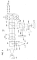
- Fig. 1 is a diagram showing schematically the structure of first optical pickup apparatus PU1 capable of conducting recording and reproducing of information properly for any of high density optical disc HD (first optical disk), DVD (second optical disk) and CD (third optical disk).
- first wavelength ⁇ 1 is 408 nm
- thickness t1 of first protective layer PL1 is 0.0875 mm and numerical aperture NA1 is 0.85
- second wavelength ⁇ 2 is 658 nm
- thickness t2 of second protective layer PL2 is 0.6 mm and numerical aperture NA2 is 0.60
- third wavelength ⁇ 3 is 785 nm
- thickness t3 of third protective layer PL3 is 1.2 mm and numerical aperture NA3 is 0.45.
- Optical pickup apparatus PU1 is substantially composed of violet semiconductor laser LD 1 (first light source) that emits a laser light flux (first light flux) with wavelength of 408 nm radiated when conducting recording and reproducing of information for high density optical disc HD, red semiconductor laser LD 2 (second light source) that emits a laser light flux (second light flux) with wavelength of 658 nm radiated when conducting recording and reproducing of information for DVD, infrared semiconductor laser LD 3 (third light source) that emits a laser light flux (third light flux) with wavelength of 785 nm radiated when conducting recording and reproducing of information for first photo-detector PD1 that receives reflected light flux coming from information recording surface RL1 of high density disc HD and for CD, second photo-detector PD2 that receives reflected light flux coming from information recording surface RL2 of DVD or from information recording surface RL3 of CD, objective optical system OBJ having therein diffractive optical element L1 in which a diffractive structure is formed on
- violet semiconductor laser LD1 when conducting recording and reproducing for high density optical disc HD, violet semiconductor laser LD1 is made to radiate as its light path is shown with solid lines in Fig. 1.
- a divergent light flux emitted from the violet semiconductor laser LD1 is transmitted through the first polarization beam splitter BS1 after being converted into a parallel light flux by the first collimator lens COL1, then, is regulated in terms of a light flux diameter by the diaphragm STO after being transmitted through the beam expander EXP and the second polarization beam splitter BS2, and becomes a spot formed by the objective optical system OBJ on the information recording surface RL1 through the first protective layer PL1.
- the objective optical system OBJ conducts focusing and tracking with the biaxial actuator AC1 that is arranged around the objective optical system OBJ.
- the reflected light flux modulated by information pits on the information recording surface RL1 passes again through the objective optical system OBJ, the second polarization beam splitter BS2, and beam expander EXP, then, is reflected by the first polarization beam splitter BS1, then, is given astigmatism by the sensor lens SEN1, and is converted into a converged light flux by the third collimator lens COL3 to be converged on a light-receiving surface of the first photo-detector PD1.
- red semiconductor laser LD2 When conducting recording and reproducing of information for DVD, red semiconductor laser LD2 is made to radiate first. A divergent light flux emitted from the red semiconductor laser LD2 passes through the third polarization beam splitter and the fourth polarization beam splitter as its light path is shown with dotted lines in Fig. 1, and is converted into a parallel light flux by the second collimator lens COL2. After that, the light flux is reflected by the second beam splitter BS2 and becomes a spot formed by the objective optical system OBJ on the information recording surface RL2 through the second protective layer PL2. The objective optical system OBJ conducts focusing and tracking with the biaxial actuator AC1 that is arranged around the objective optical system OBJ.
- the reflected light flux modulated by information pits on the information recording surface RL2 passes again through the objective optical system OBJ, and is reflected on the second polarization beam splitter BS2, then, is converted into a convergent light flux by the second collimator lens COL2, and is reflected by the fourth polarization beam splitter BS4, then, is given astigmatism by the second sensor lens SEN2, to be converged on a light-receiving surface of the second photo-detector PD2.
- infrared semiconductor laser LD3 When conducting recording and reproducing of information for CD, infrared semiconductor laser LD3 is made to radiate. A divergent light flux emitted from the infrared semiconductor laser LD3 is reflected by the third polarization beam splitter, and passes through the fourth polarization beam splitter as its light path is shown with dotted lines in Fig. 1, and is converted into a parallel light flux by the second collimator lens COL2. After that, the light flux is reflected by the second beam splitter BS2 and becomes a spot formed by the objective optical system OBJ on the information recording surface RL3 through the third protective layer PL3. The objective optical system OBJ conducts focusing and tracking with the biaxial actuator AC1 that is arranged around the objective optical system OBJ.
- the reflected light flux modulated by information pits on the information recording surface RL3 passes again through the objective optical system OBJ, and is reflected on the second polarization beam splitter BS2, then, is converted into a convergent light flux by the second collimator lens COL2, and is reflected by the fourth polarization beam splitter BS4, then, is given astigmatism by the second sensor lens SEN2, to be converged on a light-receiving surface of the second photo-detector PD2.
- Diffractive optical element L1 is a plastic lens whose refractive index nd for d line is 1.5091, Abbe's number vd is 56.5 and its refractive index for ⁇ 1 is 1.5242, refractive index for ⁇ 2 is 1.5064 and refractive index for ⁇ 3 is 1.5050.
- Light converging element L2 is a plastic lens.whose refractive index nd for d line is 1.5435 and Abbe's number vd is 56.3.
- optical functional sections areas for the diffractive optical element L1 through which the first light flux passes and for the light converging element L2 have, around them, flange portions each being formed to be united with each optical functional section, respectively, and the optical functional sections are united solidly when a part of each flange portion is connected with that of another flange portion.
- the diffractive optical element L1 and the light converging element L2 are united solidly, they may also be united through a lens frame that is an another member.
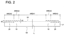
- Optical surface S1 (surface of incidence) of the diffractive optical element L1 closer to the semiconductor laser light source is divided, as shown in Fig. 2, into first area AREA1 that is in a form of concentric circles corresponding to an area within NA3 each having a center on an optical axis and includes optical axis L, second area AREA1 that is in a form of concentric circles corresponding to an area within NA2 each having a center on an optical axis and is formed outside the first area AREA1 and is equipped with first diffractive structure 10 and third area AREA3 that is in a form of concentric circles corresponding to an area within NA1 and is formed outside the first area AREAL and is equipped with second diffractive structure 20.
- f1 x NA1 > f2 x NA2 > f3 x NA3 is satisfied, and it is preferable to give diffracting actions to the second light flux passing through the third area.
- each of f1, f2 and f3 represents a focal length of the objective optical element for each wavelength
- each of NA1, NA2 and NA3 represents a numerical aperture necessary for recording or reproducing of each optical disc.
- the opening aperture NA1, NA2 and NA3 of the above structure which satisfy the following expressions are listed, for example. 0.75 ⁇ NA1 ⁇ 0.90 0.60 ⁇ NA2 ⁇ 0.70 0.43 ⁇ NA3 ⁇ 0.55
- NA1, NA2 and NA3 which satisfy the following expressions may also be provided. 0.65 ⁇ NA1 ⁇ 0.70 0.60 ⁇ NA2 ⁇ 0.63 0.43 ⁇ NA3 ⁇ 0.55
- f2 x NA2 > f1 x NA1 > f3 x NA3 is satisfied, and it is preferable to give diffracting actions to the first light flux passing through the third area.
- each of f1, f2 and f3 represents a focal length of the objective optical element for each wavelength
- each of NA1, NA2 and NA3 represents a numerical aperture necessary for recording or reproducing of each optical disc.
- the opening aperture NA1, NA2 and NA3 of the above structure which satisfy the following expressions are listed, for example. 0.64 ⁇ NA1 ⁇ 0.65 0.64 ⁇ NA2 ⁇ 0.70 0.43 ⁇ NA3 ⁇ 0.55
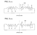
- this diffractive structure is called "diffractive structure HOE"
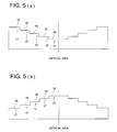
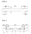
- a structure that is organized by a plurality of ring-shaped zones 15, and has a form of sectional view including optical axis L which is in a form of serration as shown schematically in Figs.
- each of Fig. 3 (a) - Fig. 5 (b) is one showing schematically an occasion wherein each diffractive structure is formed on a plane, and each diffractive structure may also be formed on a spherical surface or on an aspheric surface.
- each of the first diffractive structure 10 formed on the second area AREA2 and the second diffractive structure 20 formed on the third area AREA3 is organized by the diffractive structure HOE as shown in Figs. 3 (a) and 3 (b).
- the first light flux with wavelength ⁇ 1 and the second light flux with wavelength ⁇ 2 enter the first diffractive structure 10 wherein depth d1 of the step portion in the optical axis direction and number M1 of discontinuous portions are established so that they may satisfy the above-mentioned ranges, there is generated an optical path difference that is substantially a multiple of an integer of ⁇ 1 ( ⁇ m) and ⁇ 2 ( ⁇ m) between adjoining stair-structures, and neither the first light flux nor the second light flux is given a phase difference substantially. Therefore, the light fluxes are transmitted as they are without being diffracted to arrive at light converging element L2 (this is called "0-order diffracted light").
- a light flux having passed through the first area AREA1 among the third light flux is used. Therefore, the third light flux having passed through the second area AREA2 where the first diffractive structure 10 is provided is unwanted light. Therefore, the diffractive actions are given by the first diffractive structure 10 so that the third light flux having passed through the first diffractive structure 10 may not be converged on information recording surface RL3, and thereby, the diffracted light having relatively high diffraction efficiency (for example, 30% or more) among diffracted light with different order generated is made to be a flare.
- the first light flux with wavelength ⁇ 1 enters the second diffractive structure 20 wherein depth d2 of the step portion in the optical axis direction and number M2 of discontinuous portions are established so that they may satisfy the above-mentioned ranges, there is generated an optical path difference that is substantially a multiple of an integer of ⁇ 1 ( ⁇ m) between adjoining stair-structures, and the first light flux is not given a phase difference substantially. Therefore, the light flux is transmitted as it is as 0-order diffracted light to arrive at light converging element L2.
- the second light flux and the third light flux having passed through the third area AREA3 where the second diffractive structure 20 is provided are made to be unwanted light. Therefore, the diffractive actions are given by the second diffractive structure 20 so that the second light flux and the third light flux having passed through the second diffractive structure 20 may not be converged on information recording surfaces RL2 and RL3 of DVD and CD respectively, and thereby, the diffracted light having relatively high diffraction efficiency (for example, 30% or more) among diffracted light with different order generated is made to be a flare.
- the first - the third light fluxes are not diffracted in the first area AREA1, and pass through it as it is.
- the first - third light fluxes having passed through the first area AREA1 pass through diffractive optical element L1, then, receive refractive actions in the light converging element L2, and form converged spots respectively on information recording surfaces of prescribed optical discs.
- first and the second light fluxes having passed through the second area AREA2 pass through diffractive optical element L1, then, receive refractive actions in the light converging element L2, and form converged spots respectively on information recording surfaces of prescribed optical discs.
- the first light flux having passed through the third area AREA3 passes through diffractive optical element L1, then, receive refractive actions in the light converging element L2, and forms converged spot on information recording surface RL1 of high density optical disc.
- the optical surface S1 (surface of incidence) thereof on the semiconductor laser light source side is divided into the first area AREA1 - the third area AREA3, and the first diffractive structure 10 is formed on the second area AREA2, while the second diffractive structure 20 is formed on the third area AREA3.
- the second area AREA2 on which the first diffractive structure 10 is formed and the third area AREA3 on which the second diffractive structure 20 is formed on the same optical surface (for example, surface of incidence) of the diffractive optical element L1 it is possible to provide separately the structure for correcting chromatic aberration caused by a wavelength difference between light fluxes and the structure for correcting spherical aberration changes caused by temperature changes, on the side of the surface of emergence.
- the first diffractive structure 10 is formed on the second area AREA2 corresponding to NA2, then, the second diffractive structure 20 is provided on the area corresponding to the inside of NA1 and the third light flux passing through the first diffractive structure 10 and the second diffractive structure 20 is made to be a flare component that does not contribute to formation of a spot on information recording surface RL3 of CD, which can make objective optical element OBJ to have an aperture regulating function relating to NA3.
- the second light flux passing through the second diffractive structure 20 is made to be a flare component that does not contribute to formation of a spot on information recording surface RL2 of DVD, which can make objective optical element OBJ to have an aperture regulating function relating to NA2.
- optical pickup apparatus having compatibility for three types of optical discs, it is not necessary to use a dichroic filter or a liquid crystal phase control element, for example, as an aperture regulating means, thus, it is possible to keep a manufacturing cost for optical pickup apparatuss down.
- the structure of the optical pickup apparatus in the present embodiment is substantially the same as that in the First Embodiment except the structure of diffractive optical element L1 which, therefore, will be explained as follows.
- first area AREAL which is in a form of concentric circles each having its center on optical axis L corresponding to an area within NA3, and includes the optical axis L and is provided with first diffractive structure 10
- second area AREA2 which is in a form of concentric circles each having its center on optical axis L corresponding to an area within NA2, and is formed on an area outside the fist area AREAL and is provided with second diffractive structure 20, and third area AREA3 which is in a form of concentric circles each having its center on optical axis L corresponding to an area within NA1, and is formed on an area outside the fist area AREA1.
- the second area AREA2 is further divided into 2A area that is in a form of concentric circles each having its center on optical axis L and is closer to the optical axis L and 2B area that is farther from the optical axis, and a form of the second diffractive structure 20 formed on the 2A area and a form of the second diffractive structure 20 formed on the 2B area are designed to be different each other.
- the first light flux with wavelength ⁇ 1 and the third light flux with wavelength ⁇ 3 enter the first diffractive structure 10 wherein depth d1 of the step portion in the optical axis direction and number M1 of discontinuous portions are established so that they may satisfy the above-mentioned ranges, there is generated an optical path difference that is substantially a multiple of an integer of ⁇ 1 ( ⁇ m) and ⁇ 3 ( ⁇ m) between adjoining stair-structures, and neither the first light flux nor the third light flux is given a phase difference substantially. Therefore, the light fluxes are transmitted as they are as a zero-order diffracted light without being diffracted to arrive at light converging element L2.
- the second light flux with wavelength ⁇ 2 enters the first diffractive structure 10
- the second light flux is diffracted by the optical path difference generated between adjoining stair-structures, and the diffracted light having the highest diffraction efficiency among the second light fluxes is converged on an information recording surface of DVD.
- the first light flux with wavelength ⁇ 1 enters the second diffractive structure 20 wherein depth d2 of the step portion in the optical axis direction and number M2 of discontinuous portions are established so that they may satisfy the above-mentioned ranges, there is generated an optical path difference that is substantially a multiple of an integer of ⁇ 1 ( ⁇ m) and the first light flux is given a phase difference substantially. Therefore, the light flux is transmitted as it is as a zero-order diffracted light to arrive at light converging element L2.
- the second light flux with wavelength ⁇ 2 and the third light flux with wavelength ⁇ 3 enter the second diffractive structure 20
- the second light flux and the third light flux are diffracted by the optical path difference generated between adjoining stair-structures, and the diffracted light having the highest diffraction efficiency among the second light fluxes is converged on information recording surface RL of DVD
- the diffracted light of the third light flux is made to be a flare so that it may not be converged on information recording surface RL3 of CD.
- the second light flux and the third light flux among the first - third light fluxes passing though the third area AREA3 are subjected to refraction actions by the light converging element L2 and thereby, are made to be a flare so that both of them may not be converged respectively on prescribed optical discs.
- the first light flux - the third light flux having passed through the first area AREA1 pass through diffractive optical element L1, and then, are given refraction actions in the light converging element L2, and form respectively converged spots on information recording surfaces of prescribed optical discs.
- first light flux and the second light flux having passed through the second area AREA2 pass through diffractive optical element L1, and then, are given refraction actions in the light converging element L2, and form respectively converged spots on information recording surfaces of prescribed optical discs.
- the first light flux having passed through the third area AREA3 passes through diffractive optical element L1, and then, is given refraction actions in the light converging element L2, and forms a converged spot on information recording surface RL1 of high density optical disc HD.
- the first diffractive structure 10 is formed on the first area AREA1 corresponding to NA3, then, the second diffractive structure 20 is provided on the area corresponding to the inside of NA2 and the third light flux passing through the first diffractive structure 10 and the second diffractive structure 20 is made to be a flare component that does not contribute to formation of a spot on information recording surface RL3 of CD, which can make objective optical element OBJ to have an aperture regulating function relating to NA3.
- the second light flux passing through the third area AREA3 is made to be a flare component that does not contribute to formation of a spot on information recording surface RL2 of DVD, which can make objective optical element OBJ to have an aperture regulating function relating to NA2.
- optical pickup apparatus having compatibility for three types of optical discs, it is not necessary to use a dichroic filter or a liquid crystal phase control element, for example, as an aperture regulating means, thus, it is possible to keep a manufacturing cost for optical pickup apparatuss down.
- the second area AREA2 is divided into two areas including 2A area and 2B area, and a form of second diffractive structure 20 formed in the 2A area and a form of second diffractive structure 20 formed in the 2B area are designed to be different each other. Due to this, longitudinal spherical aberration of the third light flux from the first area AREAL to the 2A area can be made to be discontinuous, thus, it is possible to improve accuracy of detection for a reflected light of the third light flux in second photodetector PD2.
- the 2A area may also be provided on the surface of emergence S2 side, and even in this case, longitudinal spherical aberration of the third light flux from the first area AREAL to the 2A area can be made to be discontinuous, and it is possible to improve accuracy of detection for a reflected light of the third light flux in second photodetector PD2.
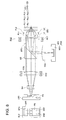
- the structure of the optical pickup apparatus is not limited to one shown in Fig. 1, and it can be modified freely to, for example, the structure shown in Fig. 8.
- Optical pickup apparatus PU2 shown in Fig. 8 is composed of laser module LM1 for high density optical disc HD and DVD composed of first light-emitting point EP1 (first light source) that emits a laser light flux (first light flux) with wavelength of 408 nm emitted when conducting recording and reproducing of information for high density optical disc HD, second light-emitting point EP2 (first light source) that emits a laser light flux (second light flux) with wavelength of 658 nm emitted when conducting recording and reproducing of information for DVD, first light-receiving section DS1 that receives a reflected light flux coming from information recording surface RL1 of high density optical disc HD, second light-receiving section DS2 that receives a reflected light flux coming from information recording surface RL2 of DVD and prism PS, module MD1 for CD wherein infrared semiconductor laser LD3 (third light source) that emits a laser light flux (third light flux) with wavelength of 785 nm emitted when conducting recording and reproduc
- a diffractive optical element is made to be one constituting a part of an objective optical element.
- the diffractive optical element can also be arranged to be separate from the objective optical element, without being limited to the foregoing.
- an optical surface (surface of incidence S1 and surface of emergence S2) of diffractive optical element L1 is in a form of a plane, and depth d1 and d2 of the step portions in the optical axis direction are within the above-mentioned ranges when the first diffractive structure 10 and the second diffractive structure 20 are formed on an optical surface in a form of a plane.
- first diffractive structure 10 and the second diffractive structure 20 on an optical surface which is in a form of a spherical surface or an aspheric surface, as stated above, and when an optical surface of the diffractive optical element L1 is inclined at the prescribed angle or more (for example, 10° or more) from incident light, for example, it is preferable to design so that an optical path length of the light flux entering the first diffractive structure 10 and the second diffractive structure 20 is within the-aforementioned range concerning d1 and d2.
- Example 1 will be explained as follows.
- an optical pickup apparatus shown in Fig. 1 is used to divide a surface of incidence (first surface) of the diffractive optical element shown in Fig. 6 into first area AREA1 (height h from an optical axis satisfying 0.00 mm ⁇ h ⁇ 1.27 mm) and second area AREA2 (1.27 mm ⁇ h), and the first diffractive structure is formed on the second area AREA2, third area AREA3 (1.635 mm ⁇ h) is provided on a surface of emergence (second surface) of the diffractive optical element, and the second diffractive structure is formed on the third area AREA3.
- the first area AREA1 is a refracting interface.
- diffractive structure HOE wherein ring-shaped zones in a form of concentric circles each having its center on an optical axis having therein a stairs-structure composed of step portions and discontinuous portions in prescribed quantity as shown schematically in Figs, 3 (a) and 3 (b) are formed periodically.
- ri represents a radius of curvature
- di represents a displacement from i th surface to (i + 1) th surface
- ni represents a refractive index of each surface.
- number M1 of discontinuous portions in the first diffractive structure is 2, and number M2 of discontinuous portions in the second diffractive structure is 2.
- Each of a surface of incidence (first surface) and a surface of emergence (second surface) of the diffractive optical element and a surface of incidence (third surface) and a surface of emergence (fourth surface) of the light converging element is formed to be an aspheric surface that is stipulated by a numerical expression wherein a coefficient shown in Tables 1-1 and 1-2 is substituted respectively in Numeral 1, and is rotationally symmetrical on the optical axis.
- X (h) represents an axis in the optical axis direction (traveling direction of light is positive)
- ⁇ represents a conic constant
- a 2i represents a coefficient of aspheric surface.
- An optical path length given to each light flux having each wavelength by each of the first diffractive structure and the second diffractive structure is stipulated by a numerical expression wherein a coefficient shown in Tables 1-1 and 1-2 is substituted in the optical path difference function of Numeral 2.
- B 2i represents a coefficient of the optical path difference function.
- Depth d1 of the step portion in the optical axis direction in the first diffractive structure is established so that an optical path difference equivalent to ⁇ 1 x 5 wavelength may be given, and due to this, an optical path difference equivalent to about 3 wavelengths is given to the second light flux with wavelength ⁇ 2, but, an amount of change of phase is less for the first light flux with wavelength ⁇ 1 and the second light flux with wavelength ⁇ 2, and diffraction actions are not generated. Only for the third light flux with wavelength ⁇ 3, a phase difference equivalent to about 0.5 wavelengths ( ⁇ ) is given, and diffraction actions are generated.
- Depth d2 of the step portion in the optical axis direction in the second diffractive structure is established so that an optical path difference equivalent to ⁇ 1 x 4 wavelength may be given, and due to this, an optical path difference equivalent to about 2 wavelengths is given to the second light flux, but, an amount of change of phase is less for the first light flux and the third light flux, and diffraction actions are not generated. Only for the second light flux, a phase difference equivalent to about 0.5 wavelengths ( ⁇ ) is given, and diffraction actions are generated.
- Fig. 9 shows longitudinal spherical aberration diagrams respectively for the first light flux (BD), the second light flux (DVD) and the third light flux (CD).
- Fig. 9 shows that longitudinal spherical aberration is controlled in the necessary numerical aperture for all of the first - third light fluxes, and longitudinal spherical aberration is discontinuous in an area where a height from the optical axis exceeds the necessary numerical aperture and the objective optical system has an excellent aperture regulating function for the second and the third light fluxes.
- Example 2 will be explained as follows.
- an optical pickup apparatus shown in Fig. 1 is used to divide a surface of incidence (first surface) of the diffractive optical element shown in Fig. 7 into the first area AREA1 (0.00 mm ⁇ h ⁇ 1.17 mm), the 2A th area (1.17 mm ⁇ h ⁇ 1.44 mm), the 2B th area (1.44 mm ⁇ h ⁇ 1.54 mm) and the third area AREA3 (1.54 mm ⁇ h), and the first diffractive structure is formed on the first area AREA1 and the second diffractive structure is formed on each of the 2A th and the 2B th areas.
- the third area AREA3 is a refracting interface.
- each of the surface of incidence and the surface of emergence of the diffractive optical element is in a shape of a flat surface.
- diffractive structure HOE wherein ring-shaped zones in a form of concentric circles each having its center on an optical axis having therein a stairs-structure composed of step portions and discontinuous portions in prescribed quantity as shown schematically in Figs, 3 (a) and 3 (b) are formed periodically.
- Lens data are shown in Tables 2-1 and 2-2.
- Diffraction data First surface 0.0mm ⁇ h ⁇ 1.17mm
- Coefficient of optical path difference function B4 -5.4454E-04 B6 -6.1686E-05 B8 -1.4718E-05 * Number of discontinuous portions of each diffractive ring-shaped zone 5
- Amount of level difference 2 x 407/0.53 nm (Amount of level difference provided with optical path difference of 2 x wavelength 407 nm) .
- number M1 of discontinuous portions in the first diffractive structure is 5
- number M2 of discontinuous portions in the 2A area among the second diffractive structure is 2
- number M2 of discontinuous portions in the 2B area is 5.
- Each of a surface of incidence (third surface) and a surface of emergence (fourth surface) of the light converging element is formed to be an aspheric surface that is stipulated by a numerical expression wherein a coefficient shown in Tables 2-1 and 2-2 is substituted respectively in Numeral 1, and is rotationally symmetrical on the optical axis.
- An optical path length given to each light flux having each wavelength by each of the first diffractive structure and the second diffractive structure is stipulated by a numerical expression wherein a coefficient shown in Tables 2-1 and 2-2 is substituted in the optical path difference function of Numeral 2.
- Depth d1 of the step portion in the optical axis direction in the first diffractive structure is established so that an optical path difference equivalent to ⁇ 1 x 2 wavelength may be given, and due to this, an optical path difference equivalent to about 1 wavelength is given to the third light flux, thus, an amount of change of phase is less for the first light flux and the third light flux, and diffraction actions are not generated. Only for the second light flux, a phase difference equivalent to about 0.2 wavelengths (0.4 ⁇ ) is given, and diffraction actions are generated.
- Depth d2 of the step portion in the optical axis direction in the second diffractive structure in the 2A area is established so that an optical path difference equivalent to ⁇ 1 x 1 wavelength may be given, and due to this, a phase of the first light flux remains unchanged, and diffraction actions are not generated.
- a phase difference equivalent to about 0.4 wavelengths (0.8 ⁇ ) is given
- a phase difference equivalent to about 0.5 wavelengths ( ⁇ ) is given, and diffraction actions are generated.
- depth d2 of the step portion in the optical axis direction in the second diffractive structure 20 in the 2B area is established so that an optical path difference equivalent to ⁇ 1 x 2 wavelength may be given, and due to this, an optical path difference equivalent to about 1 wavelength is given to the third light flux, thus, phases of the first light flux and the third light flux remain unchanged, and diffraction actions are not generated.
- a phase difference equivalent to about 0.2 wavelengths (0.4 ⁇ ) is given, and diffraction actions are generated.
- Fig. 10 shows longitudinal spherical aberration diagrams respectively for the first light flux (BD), the second light flux (DVD) and the third light flux (CD).
- Fig. 10 shows that longitudinal spherical aberration is controlled in the necessary numerical aperture for all of the first - third light fluxes, and longitudinal spherical aberration is discontinuous in an area where a height from the optical axis exceeds the necessary numerical aperture and the objective optical system has an excellent aperture regulating function for the second and the third light fluxes.
- an optical pickup apparatus shown in Fig. 1 is used to divide a surface of incidence (first surface) of the diffractive optical element shown in Fig. 11 into the first area AREA1 (0.00 mm ⁇ h ⁇ 1.644 mm), the second area AREA2 (1.644 mm ⁇ h ⁇ 1.902 mm), the third area AREA3 (1.902 mm ⁇ h), and the first diffractive structure 10 is formed on the second area AREA2 and the second diffractive structure 20 is formed on the third area.
- the first area AREA1 is a refracting interface.
- diffractive structure HOE wherein ring-shaped zones in a form of concentric circles each having its center on an optical axis having therein a stairs-structure composed of step portions and discontinuous portions in prescribed quantity as shown schematically in Figs, 3 (a) and 3 (b) are formed periodically.
- Lens data are shown in Tables 3-1 and 3-2.
- number M1 of discontinuous portions in the first diffractive structure is 2 and number M2 of discontinuous portions in the second diffractive structure is 3.
- Each of a surface of incidence (third surface) and a surface of emergence (fourth surface) of the light converging element is formed to be an aspheric surface that is stipulated by a numerical expression wherein a coefficient shown in Tables 3-1 and 3-2 is substituted respectively in Numeral 1, and is rotationally symmetrical on the optical axis.
- An optical path length given to each light flux having each wavelength by each of the first diffractive structure and the second diffractive structure is stipulated by a numerical expression wherein a coefficient shown in Tables 3-1 and 3-2 is substituted in the optical path difference function of Numeral 2.
- Depth d1 of the step portion in the optical axis direction in the first diffractive structure is established so that an optical path difference equivalent to ⁇ 1 x 3 wavelength may be given, and due to this, an optical path difference equivalent to about 2 wavelength is given to the third light flux, thus, an amount of change of phase is less for the first light flux and the third light flux, and diffraction actions are not generated. Only for the second light flux, a phase difference equivalent to about 0.5 wavelengths (n) is given, and diffraction actions are generated.
- Depth of the step portion in the optical axis direction in the second diffractive structure in the second area is established so that an optical path difference equivalent to ⁇ 2 x 1 wavelength may be given, and due to this, a phase of the second light flux remains unchanged, and diffraction actions are not generated.
- a phase difference equivalent to about 0.4 wavelengths (0.8 ⁇ ) is given
- a phase difference equivalent to about 0.5 wavelengths ( ⁇ ) is given, and diffraction actions are generated.
- Fig. 12 shows longitudinal spherical aberration diagrams respectively for the first light flux (HD DVD), the second light flux (DVD) and the third light flux (CD).
- Fig. 12 shows that longitudinal spherical aberration is controlled in the necessary numerical aperture for all of the first - third light fluxes, and longitudinal spherical aberration is discontinuous in an area where a height from the optical axis exceeds the necessary numerical aperture and the objective optical system has an excellent aperture regulating function for the second and the third light fluxes.
Landscapes
- Physics & Mathematics (AREA)
- Optics & Photonics (AREA)
- Engineering & Computer Science (AREA)
- Mechanical Engineering (AREA)
- Optical Head (AREA)
- Diffracting Gratings Or Hologram Optical Elements (AREA)
- Lenses (AREA)
Applications Claiming Priority (2)
| Application Number | Priority Date | Filing Date | Title |
|---|---|---|---|
| JP2004036832 | 2004-02-13 | ||
| JP2004036832 | 2004-02-13 |
Publications (2)
| Publication Number | Publication Date |
|---|---|
| EP1564731A2 true EP1564731A2 (fr) | 2005-08-17 |
| EP1564731A3 EP1564731A3 (fr) | 2008-04-16 |
Family
ID=34697925
Family Applications (1)
| Application Number | Title | Priority Date | Filing Date |
|---|---|---|---|
| EP05250762A Withdrawn EP1564731A3 (fr) | 2004-02-13 | 2005-02-10 | Appareil de lecture optique et élément optique diffractif pour appareil de lecture optique |
Country Status (5)
| Country | Link |
|---|---|
| US (1) | US20050180295A1 (fr) |
| EP (1) | EP1564731A3 (fr) |
| KR (1) | KR20060041867A (fr) |
| CN (1) | CN100479041C (fr) |
| TW (1) | TW200532679A (fr) |
Cited By (2)
| Publication number | Priority date | Publication date | Assignee | Title |
|---|---|---|---|---|
| WO2007034389A2 (fr) * | 2005-09-26 | 2007-03-29 | Koninklijke Philips Electronics N.V. | Compensateur optique, elements optiques, tete de lecture optique, et dispositif de lecture optique |
| US8089849B2 (en) | 2007-05-18 | 2012-01-03 | Samsung Electronics Co., Ltd. | Hologram optical device, and compatible optical pickup having the hologram optical device and optical information storage medium system employing the compatible optical pickup |
Families Citing this family (10)
| Publication number | Priority date | Publication date | Assignee | Title |
|---|---|---|---|---|
| US7839751B2 (en) * | 2005-02-14 | 2010-11-23 | Hoya Corporation | Objective lens and optical system for optical pick-up |
| JP4297099B2 (ja) * | 2005-08-09 | 2009-07-15 | ソニー株式会社 | 光ピックアップ及び光ディスク装置 |
| KR100924876B1 (ko) * | 2005-10-28 | 2009-11-02 | 미쓰비시덴키 가부시키가이샤 | 회절 광학 소자, 및 광 헤드 장치 |
| WO2007058348A1 (fr) * | 2005-11-21 | 2007-05-24 | Matsushita Electric Industrial Co., Ltd. | Lecteur optique, périphérique à disque optique, ordinateur et enregistreur de disque optique |
| JP2007280549A (ja) * | 2006-04-10 | 2007-10-25 | Sony Corp | 光ピックアップ及び光ディスク装置 |
| CN101479796B (zh) * | 2006-04-26 | 2011-02-09 | 株式会社理光 | 光拾取器与光学信息处理设备 |
| JP2007305256A (ja) * | 2006-05-12 | 2007-11-22 | Hitachi Maxell Ltd | 対物レンズ光学系、光ピックアップ光学系 |
| KR20080071380A (ko) * | 2007-01-30 | 2008-08-04 | 삼성전자주식회사 | 홀로그램 소자 및 이를 채용한 호환형 광픽업 장치 |
| WO2011093007A1 (fr) * | 2010-01-27 | 2011-08-04 | パナソニック株式会社 | Lentille de focalisation composée, dispositif à tête optique, dispositif d'information optique et dispositif de traitement d'informations |
| JP5647547B2 (ja) * | 2010-03-19 | 2014-12-24 | Hoya株式会社 | 光情報記録再生装置用対物光学系、及び光情報記録再生装置 |
Citations (6)
| Publication number | Priority date | Publication date | Assignee | Title |
|---|---|---|---|---|
| EP0936604A1 (fr) * | 1996-10-31 | 1999-08-18 | SANYO ELECTRIC Co., Ltd. | Dispositif de lecture optique |
| WO2002082437A1 (fr) * | 2001-04-05 | 2002-10-17 | Koninklijke Philips Electronics N.V. | Dispositif de lecture optique |
| US20030067686A1 (en) * | 2001-10-05 | 2003-04-10 | Matsushita Electric Industrial Co., Ltd. | Diffractive optical element and optical head using the same |
| EP1304689A2 (fr) * | 2001-10-12 | 2003-04-23 | Konica Corporation | Lentille d'objectif, élément d'objectif, dispositif de lecture d'objectif et appareil d'enregistrement et/ou de reproduction d'informations muni de ce dispositif |
| WO2003091764A1 (fr) * | 2002-04-18 | 2003-11-06 | Matsushita Electric Industrial Co., Ltd. | Element optique, tete optique, dispositif d'enregistrement/reproduction d'informations optiques, ordinateur, dispositif d'enregistrement video, dispositif de reproduction video, serveur et systeme de navigation de vehicule |
| WO2004012188A1 (fr) * | 2002-07-31 | 2004-02-05 | Asahi Glass Company, Limited | Element de correction de phase et dispositif de tete optique |
Family Cites Families (4)
| Publication number | Priority date | Publication date | Assignee | Title |
|---|---|---|---|---|
| US6061324A (en) * | 1996-10-23 | 2000-05-09 | Konica Corporation | Method for recording/reproducing optical information recording medium, optical pickup apparatus, objective lens and design method of objective lens |
| TW479253B (en) * | 1998-12-17 | 2002-03-11 | Konishiroku Photo Ind | Objective lens for correcting chromatic aberration for use in recording toor reproducing from optical information recording medium and optical pickup apparatus therewith |
| US7577077B2 (en) * | 2002-09-05 | 2009-08-18 | Konica Corporation | Optical pickup apparatus and optical element |
| US7239598B2 (en) * | 2003-06-17 | 2007-07-03 | Pentax Corporation | Objective lens for optical pick-up |
-
2005
- 2005-02-05 TW TW094104091A patent/TW200532679A/zh unknown
- 2005-02-10 EP EP05250762A patent/EP1564731A3/fr not_active Withdrawn
- 2005-02-10 US US11/053,950 patent/US20050180295A1/en not_active Abandoned
- 2005-02-11 KR KR1020050011624A patent/KR20060041867A/ko not_active Application Discontinuation
- 2005-02-16 CN CNB2005100519071A patent/CN100479041C/zh not_active Expired - Fee Related
Patent Citations (6)
| Publication number | Priority date | Publication date | Assignee | Title |
|---|---|---|---|---|
| EP0936604A1 (fr) * | 1996-10-31 | 1999-08-18 | SANYO ELECTRIC Co., Ltd. | Dispositif de lecture optique |
| WO2002082437A1 (fr) * | 2001-04-05 | 2002-10-17 | Koninklijke Philips Electronics N.V. | Dispositif de lecture optique |
| US20030067686A1 (en) * | 2001-10-05 | 2003-04-10 | Matsushita Electric Industrial Co., Ltd. | Diffractive optical element and optical head using the same |
| EP1304689A2 (fr) * | 2001-10-12 | 2003-04-23 | Konica Corporation | Lentille d'objectif, élément d'objectif, dispositif de lecture d'objectif et appareil d'enregistrement et/ou de reproduction d'informations muni de ce dispositif |
| WO2003091764A1 (fr) * | 2002-04-18 | 2003-11-06 | Matsushita Electric Industrial Co., Ltd. | Element optique, tete optique, dispositif d'enregistrement/reproduction d'informations optiques, ordinateur, dispositif d'enregistrement video, dispositif de reproduction video, serveur et systeme de navigation de vehicule |
| WO2004012188A1 (fr) * | 2002-07-31 | 2004-02-05 | Asahi Glass Company, Limited | Element de correction de phase et dispositif de tete optique |
Cited By (3)
| Publication number | Priority date | Publication date | Assignee | Title |
|---|---|---|---|---|
| WO2007034389A2 (fr) * | 2005-09-26 | 2007-03-29 | Koninklijke Philips Electronics N.V. | Compensateur optique, elements optiques, tete de lecture optique, et dispositif de lecture optique |
| WO2007034389A3 (fr) * | 2005-09-26 | 2008-11-06 | Koninkl Philips Electronics Nv | Compensateur optique, elements optiques, tete de lecture optique, et dispositif de lecture optique |
| US8089849B2 (en) | 2007-05-18 | 2012-01-03 | Samsung Electronics Co., Ltd. | Hologram optical device, and compatible optical pickup having the hologram optical device and optical information storage medium system employing the compatible optical pickup |
Also Published As
| Publication number | Publication date |
|---|---|
| KR20060041867A (ko) | 2006-05-12 |
| US20050180295A1 (en) | 2005-08-18 |
| CN100479041C (zh) | 2009-04-15 |
| EP1564731A3 (fr) | 2008-04-16 |
| TW200532679A (en) | 2005-10-01 |
| CN1655258A (zh) | 2005-08-17 |
Similar Documents
| Publication | Publication Date | Title |
|---|---|---|
| EP1564731A2 (fr) | Appareil de lecture optique et élément optique diffractif pour appareil de lecture optique | |
| JP2011014236A (ja) | 光ピックアップ装置用の対物光学系、光ピックアップ装置、光情報記録媒体のドライブ装置、集光レンズ、及び光路合成素子 | |
| EP1359574A2 (fr) | Système optique d'enregistrement / de reproduction, lentille d'objectif et élément optique de correction d'aberration | |
| US20060092816A1 (en) | Objective optical system and optical pick up apparatus | |
| KR20060115879A (ko) | 대물 광학계, 광픽업 장치 및 광정보 기록 재생 장치 | |
| US7664003B2 (en) | Objective lens and optical pickup apparatus | |
| EP1610313A2 (fr) | Elément optique convergent et appareil de lecture optique | |
| JP2005259332A (ja) | 光ピックアップ装置及び光ピックアップ装置用回折光学素子 | |
| JP2008293630A (ja) | 光ピックアップ装置及び対物光学素子 | |
| JP5024041B2 (ja) | 光ピックアップ装置用対物光学素子、光ピックアップ装置用光学素子、光ピックアップ装置用対物光学素子ユニット及び光ピックアップ装置 | |
| WO2005043523A1 (fr) | Capteur optique et element de conversion d'angle divergent | |
| US20090103419A1 (en) | Optical Pickup Device, Optical Information Recording and Reproducing Device and Design, Method of Optical Element | |
| US7706237B2 (en) | Objective lens and optical pickup apparatus | |
| JPWO2005048250A1 (ja) | 光ピックアップ装置及びそれに用いられる光学素子 | |
| EP1538613A2 (fr) | Tête optique et appareil d'enregistrement et/ou de lecture optique d'informations | |
| US7460460B2 (en) | Objective optical system, optical pickup apparatus and optical information recording and reproducing apparatus | |
| JPWO2005088625A1 (ja) | 対物光学素子及び光ピックアップ装置 | |
| JP2005322301A (ja) | 波長選択素子、対物光学系、光ピックアップ装置、及び光ディスクのドライブ装置 | |
| JP4329031B2 (ja) | 光ピックアップ装置 | |
| JP4407421B2 (ja) | 光学素子及び光ピックアップ装置 | |
| JPWO2004088648A1 (ja) | 集光光学系 | |
| JP2005141800A (ja) | 発散角変換素子及び光ピックアップ装置 | |
| US20060164967A1 (en) | Objective lens and optical pickup device | |
| JP4329329B2 (ja) | 光学素子及び光ピックアップ装置 | |
| JP4706481B2 (ja) | 光ピックアップ装置 |
Legal Events
| Date | Code | Title | Description |
|---|---|---|---|
| PUAI | Public reference made under article 153(3) epc to a published international application that has entered the european phase |
Free format text: ORIGINAL CODE: 0009012 |
|
| AK | Designated contracting states |
Kind code of ref document: A2 Designated state(s): AT BE BG CH CY CZ DE DK EE ES FI FR GB GR HU IE IS IT LI LT LU MC NL PL PT RO SE SI SK TR |
|
| AX | Request for extension of the european patent |
Extension state: AL BA HR LV MK YU |
|
| PUAL | Search report despatched |
Free format text: ORIGINAL CODE: 0009013 |
|
| AK | Designated contracting states |
Kind code of ref document: A3 Designated state(s): AT BE BG CH CY CZ DE DK EE ES FI FR GB GR HU IE IS IT LI LT LU MC NL PL PT RO SE SI SK TR |
|
| AX | Request for extension of the european patent |
Extension state: AL BA HR LV MK YU |
|
| 17P | Request for examination filed |
Effective date: 20081013 |
|
| AKX | Designation fees paid |
Designated state(s): DE FR GB |
|
| 17Q | First examination report despatched |
Effective date: 20090119 |
|
| STAA | Information on the status of an ep patent application or granted ep patent |
Free format text: STATUS: THE APPLICATION IS DEEMED TO BE WITHDRAWN |
|
| 18D | Application deemed to be withdrawn |
Effective date: 20090530 |