EP1564465B1 - Electromagnetic dual valve - Google Patents
Electromagnetic dual valve Download PDFInfo
- Publication number
- EP1564465B1 EP1564465B1 EP20040026476 EP04026476A EP1564465B1 EP 1564465 B1 EP1564465 B1 EP 1564465B1 EP 20040026476 EP20040026476 EP 20040026476 EP 04026476 A EP04026476 A EP 04026476A EP 1564465 B1 EP1564465 B1 EP 1564465B1
- Authority
- EP
- European Patent Office
- Prior art keywords
- convex
- concave
- armature
- twin
- solenoid valve
- Prior art date
- Legal status (The legal status is an assumption and is not a legal conclusion. Google has not performed a legal analysis and makes no representation as to the accuracy of the status listed.)
- Not-in-force
Links
Images


Classifications
-
- F—MECHANICAL ENGINEERING; LIGHTING; HEATING; WEAPONS; BLASTING
- F16—ENGINEERING ELEMENTS AND UNITS; GENERAL MEASURES FOR PRODUCING AND MAINTAINING EFFECTIVE FUNCTIONING OF MACHINES OR INSTALLATIONS; THERMAL INSULATION IN GENERAL
- F16K—VALVES; TAPS; COCKS; ACTUATING-FLOATS; DEVICES FOR VENTING OR AERATING
- F16K31/00—Actuating devices; Operating means; Releasing devices
- F16K31/02—Actuating devices; Operating means; Releasing devices electric; magnetic
- F16K31/06—Actuating devices; Operating means; Releasing devices electric; magnetic using a magnet, e.g. diaphragm valves, cutting off by means of a liquid
- F16K31/10—Actuating devices; Operating means; Releasing devices electric; magnetic using a magnet, e.g. diaphragm valves, cutting off by means of a liquid with additional mechanism between armature and closure member
-
- Y—GENERAL TAGGING OF NEW TECHNOLOGICAL DEVELOPMENTS; GENERAL TAGGING OF CROSS-SECTIONAL TECHNOLOGIES SPANNING OVER SEVERAL SECTIONS OF THE IPC; TECHNICAL SUBJECTS COVERED BY FORMER USPC CROSS-REFERENCE ART COLLECTIONS [XRACs] AND DIGESTS
- Y10—TECHNICAL SUBJECTS COVERED BY FORMER USPC
- Y10T—TECHNICAL SUBJECTS COVERED BY FORMER US CLASSIFICATION
- Y10T137/00—Fluid handling
- Y10T137/8593—Systems
- Y10T137/877—With flow control means for branched passages
- Y10T137/87708—With common valve operator
- Y10T137/87772—With electrical actuation
Landscapes
- Engineering & Computer Science (AREA)
- General Engineering & Computer Science (AREA)
- Mechanical Engineering (AREA)
- Magnetically Actuated Valves (AREA)
Description
Die Erfindung betrifft ein Magnetdoppelventil der im Oberbegriff des Anspruchs 1 angegebenen Art.The invention relates to a magnetic double valve specified in the preamble of
Solche, aus der Praxis bekannte Magnetdoppelventile werden beispielsweise als Ventileinsatzbaugruppe konzipiert, die in einen Strömungswege enthaltenden Körper in zu den Strömungswegen führende Aufnahmebohrungen eingesetzt wird, beispielsweise um mittels der beiden Ventilglieder bestimmte Ventilfunktionen zu steuern. Da der gemeinsame Magnet beide Ventilglieder im Schließsinn gegen Ventilsitze zu betätigen hat, und wegen unvermeidlicher Fertigungstoleranzen die Betätigungshübe bis zu den Schließpositionen bzw. die Gegenkräfte der Ventilglieder unterschiedlich sein können, wird die Gleitpassung des Kraftübertragungsgliedes in der Schiebeführung so eng wie möglich gewählt, damit die Schiebeführung ein Schrägstellen des Kraftübertragungsgliedes weitgehend ausschließt. Damit werden gegebenenfalls die Schließpositionen und die Schließkräfte nicht zuverlässig definiert, denn aufgrund unvermeidlicher Fertigungs- oder Montagetoleranzen bei den Ventilsitzen kann ein Schließglied seine dichte Schließposition nicht zuverlässig erreichen, wenn das Kraftübertragungsglied wegen seiner engen Gleitpassung nur das früher aufgesetzte Ventilglied korrekt beaufschlagt.Such known from practice solenoid double valves are designed for example as a valve core assembly, which is used in a flow path containing body in leading to the flow paths receiving bores, for example, to control certain valve functions by means of the two valve members. Since the common magnet has to actuate both valve members in the closing direction against valve seats, and because of unavoidable manufacturing tolerances, the actuating strokes may be different up to the closing positions or the opposing forces of the valve members, the sliding fit of the force transmission member is selected as narrow as possible in the sliding guide so that the Sliding guide a tilting of the power transmission member largely excludes. Thus, if necessary, the closing positions and the closing forces are not reliably defined, because due to unavoidable manufacturing or assembly tolerances in the valve seats, a closing member can not reliably reach its tight closing position when the power transmission member due to its tight sliding fit only the previously patched valve member correctly applied.
Aus EP 1 036 965 A ist es bekannt, das Kraftübertragungsglied, allerdings zum Verstellen der Ventilglieder in Öffnungsrichtung, als beweglichen Waagebalken auszubilden, der sich unter der Kraft eines gemeinsamen Magneten abhängig davon schrägstellen kann, welches Ventilglied schwerer zu öffnen ist. Eine stationäre Widerlagerfläche für den Waagebalken bringt auch das andere Ventilglied über den Waagebalken in die Öffnungsposition.From
Von Interesse sind ferner: EP 0 527 393 A, US 2 708 561 A, DE 1 085 736 B.Also of interest are: EP 0 527 393 A, US 2 708 561 A,
Der Erfindung liegt die Aufgabe zugrunde, ein Magnetdoppelventil der eingangs genannten Art mit verbesserter Funktionssicherheit und einfachem Aufbau zu schaffen, insbesondere ein Magnetdoppelventil, das einen Kurzhub-Magneten zum Verstellen der beiden Ventilglieder in ihre Schließpositionen aufweist.The invention has for its object to provide a magnetic double valve of the type mentioned with improved reliability and simple design, in particular a magnetic double valve having a short-stroke magnet for adjusting the two valve members in their closed positions.
Die gestellte Aufgabe wird mit den Merkmalen des Anspruchs 1 gelöst.The stated object is achieved with the features of
In Kombination führen das radiale Sicherheitsspiel zwischen dem Schaft des Kraftübertragungsgliedes und der Schiebeführung und das die Magnetkraft übertragende Kippgelenk überraschend zu langer Standzeit mit störungsfreiem Betrieb des Magnetdoppelventils. Selbst wenn die Ventilglieder infolge Toleranzen in Bewegungsrichtung des Ankers unterschiedliche Schließpositionen haben sollten, wird die vom Magneten erzeugte Magnetkraft so auf beide Ventilglieder verteilt, dass jedes Ventilglied seine Schließposition sicher einnimmt und auch mit der erforderlichen Schließkraft aufsitzt und dicht ist. Das Übertragungsglied kann sich aufgrund des Sicherheitsspieles in der Schiebeführung etwas schrägstellen. Bei einer Schrägstellung wandert der Kraftübertragungspunkt für die Magnetkraft im Kippgelenk gegebenenfalls aus einer zunächst zentralen Lage sogar zu der Seite, an der das früher aufsetzende Ventilglied vorliegt, jedoch nur um ein kleineres Maß als der Breite der Flächen im Kippgelenk. Dadurch wird auch das später aufsetzende Ventilglied zuverlässig in seine Schließposition gebracht, und wird auch im Kippgelenk keine nennenswerte Querkraft aus der Magnetkraft erzeugt, die das Kraftübertragungsglied in der Schiebeführung verklemmen könnte.In combination, the radial safety clearance between the shaft of the power transmission member and the sliding guide and the magnetic force transmitting tilting lead surprisingly long life with trouble-free operation of the magnetic double valve. Even if the valve members should have different closing positions due to tolerances in the direction of movement of the armature, the magnetic force generated by the magnet is distributed to both valve members so that each valve member assumes its closed position securely and is also seated with the required closing force and tight. The transmission member may be slightly inclined due to the safety clearance in the sliding guide. In an inclined position, the force transmission point for the magnetic force in the tilting joint migrates from an initially central position even to the side at which the valve member is placed earlier, but only to a smaller extent than the width of the surfaces in the pivot joint. As a result, the valve member, which attaches later, is reliably brought into its closed position, and no significant lateral force is generated from the magnetic force in the tilting joint, which could jam the force transmission member in the sliding guide.
Zweckmäßig weist das Kippgelenk am Anker oder an einem axial geführten Ankerstößel und am Schaft direkt oder indirekt einander kontaktierende erste und zweite Anlageflächen in einer speziellen geometrischen Paarung auf. Diese Paarung kann sein: Eben/konvex oder konkav/konkav oder konvex/konkav oder konvex/konvex, wobei die jeweils konvexe oder konkave Fläche zumindest eine Bogenkrümmung in der Ebene aufweist, in der die beiden Ventilglieder nebeneinander liegen. Dadurch ergibt sich bei der Kraftübertragung die zum Aufsetzen beider Ventilglieder notwendige Beweglichkeit und der wünschenswerte Effekt, dass der Kraftübertragungspunkt zwischen den Flächen kaum aus der Mitte auswandert.Suitably, the tilting joint on the armature or on an axially guided armature tappet and on the shaft directly or indirectly contacting each other first and second contact surfaces in a special geometric pairing. This mating may be: flat / convex or concave / concave or convex / concave or convex / convex, with the respective convex or concave surface having at least one arc of curvature in the plane in which the two valve members are juxtaposed. This results in the power transmission necessary for placing both valve members mobility and the desirable effect that the power transmission point between the surfaces barely emigrated from the center.
Die konkave oder konvexe Bogenkrümmung kann eine Kreisbogenkrümmung sein, und zwar entweder Teil einer Zylinderfläche mit zur Ebene der Ventilglieder senkrechter Zylinderachse, oder Teil einer Kugelfläche mit dem Zentrum der Kugel in der Achse des Ankers, des Ankerstößels und/oder des Schafts. Die Ausbildung dieser Flächen ist herstellungstechnisch einfach.The concave or convex arc curvature may be a circular arc curvature, either part of a cylindrical surface having a cylinder axis perpendicular to the plane of the valve members, or part of a spherical surface having the center of the ball in the axis of the armature, the armature tappet and / or the shaft. The formation of these surfaces is manufacturing technology simple.
In der Paarung konkav/konvex können die Bogenkrümmungen gleich oder die konvexe Bogenkrümmung stärker als die konkave Bogenkrümmung sein. Es ergibt sich dadurch keine flächige Kraftübertragung, sondern eine Kraftübertragung mit Punkt- oder Linienberührung, was jedoch für die Beweglichkeit im Kippgelenk von Vorteil ist.In the concave / convex pairing, the arc curvatures may be equal or the convex arc curvature stronger than the concave arc curvature. This results in no area force transmission, but a power transmission with point or line contact, which is advantageous for the mobility in tilting joint.
Alternativ können im Kippgelenk auch ebene erste und zweite Anlageflächen vorgesehen sein, wobei die eine Anlagefläche deutlich kleiner ist als die andere und beispielsweise an einem zentrischen Fortsatz gebildet wird. Dies resultiert in einer Beweglichkeit ähnlich einem Kugelgelenk ohne zu starkes seitliches Auswandern des Kraftübertragungspunktes.Alternatively, planar first and second contact surfaces can also be provided in the tilting joint, wherein one contact surface is significantly smaller than the other and is formed, for example, on a central extension. This results in a mobility similar to a ball joint without too strong lateral migration of the power transmission point.
Bei einer weiteren, zweckmäßigen Ausführungsform ist im Kippgelenk zwischen den Anlageflächen eine Gelenkkugel angeordnet, was der Beweglichkeit im Kippgelenk auch bei Schrägstellung des Kraftübertragungsgliedes zu Gute kommt.In a further expedient embodiment, a joint ball is arranged in the tilting joint between the contact surfaces, which the mobility in tilting joint also comes in oblique position of the power transmission member to good.
Bei Verwendung einer Gelenkkugel sind folgende geometrische Paarungen der ersten und zweiten Anlageflächen zweckmäßig: Eben/eben oder eben/konkav oder eben/ konvex oder konkav/konkav oder konkav/konvex oder konvex/konvex.When using a joint ball, the following geometric pairings of the first and second abutment surfaces are expedient: flat / flat or even / concave or planar / convex or concave / concave or concave / convex or convex / convex.
Um die Gelenkkugel sicher positionieren zu können, ist es zweckmäßig, in wenigstens einer Anlagefläche einen zentrischen, vertieften Kugelsitz mit einem Durchmesser kleiner als den Kugeldurchmesser vorzusehen. Allfällige Bewegungen finden dann zwischen der anderen Anlagefläche und der Gelenkkugel statt.In order to be able to position the joint ball securely, it is expedient to provide a centric, recessed ball seat with a diameter smaller than the ball diameter in at least one contact surface. Any movements then take place between the other contact surface and the joint ball.
Die ersten und zweiten Anlageflächen können unterschiedlich groß bemessen sein.The first and second contact surfaces can be sized differently.
Die Schiebeführung ist zweckmäßig als wenigstens eine Gleitlagerbuchse ausgebildet, die in einer Aufnahmebohrung des festen Kernteils des Magneten sitzt. Das Kraftübertragungsglied wird mit dem z.B. zylindrischen Schaft in der Gleitlagerbuches geführt, wobei das Sicherheitsspiel zwischen dem Schaft und der Gleitlagerbuchse vorgesehen ist.The sliding guide is expediently designed as at least one plain bearing bush which is seated in a receiving bore of the fixed core part of the magnet. The power transmission member is connected to the e.g. cylindrical shaft guided in the plain bearing book, the safety clearance between the shaft and the plain bearing bush is provided.
Dieses Sicherheitsspiel kann ca. 2 % des Innendurchmessers der Schiebeführung betragen. Dies resultiert in einer relativ losen Gleitpassung, die jedoch für ein Magnetdoppeiventii, bei dem beide Ventilglieder von einem Magneten über das Kippgelenk in die Schließpositionen verstellt werden, zweckmäßig ist.This safety clearance can amount to approx. 2% of the inside diameter of the sliding guide. This results in a relatively loose sliding fit, which, however, is useful for a Magnetdoppeiventii in which both valve members are adjusted by a magnet via the tilting joint in the closed positions.
Schließlich wird ein baulich einfaches Konzept einer Ventileinsatzbaugruppe erzielt, wenn jedes Ventilglied in einer Einsatzhülse angeordnet wird, oberhalb der eine Einschraubhülse vorgesehen ist, in der ein Betätigungsstößel für das Ventilglied geführt wird. Das Kraftübertragungsglied liegt der Einschraubhülse mit einem Abstand gegenüber, der durch einen Überstand des Betätigungsstößels über die Einschraubhülse so groß bemessen ist, dass bei Erreichen der Schließpositionen der Ventilglieder zwischen dem Kraftübertragungsglied und den Einschraubhülsen ein Zwischenraum verbleibt und das Kraftübertragungsglied nicht auf Anschlag an einer stationären Fläche kommt.Finally, a structurally simple concept of a valve core assembly is achieved when each valve member is placed in an insert sleeve above which a screw-in sleeve is provided, in which an actuating plunger is guided for the valve member. The power transmission member is located opposite the screw-in with a distance which is dimensioned so large by a projection of the actuating plunger on the screw-in that upon reaching the closed positions of the valve members between the power transmission member and the screw-in sleeves remains a gap and not the power transmission member to stop on a stationary surface comes.
Anhand der Zeichnungen werden Ausführungsformen des Erfindungsgegenstandes erläutert. Es zeigen:
- Fig. 1
- einen Teillängsschnitt eines Magnetdoppelventils (zwei 2/2-Wegeventile) mit erregtem Magneten,
- Fig. 1A
- einen Teillängsschnitt eines anderen Magnetdoppelventils (zwei 3/2-Wegeventile), mit erregtem Magneten, und
- Fig. 2 bis 18
- verschiedene Varianten eines Kippgelenks für das Magnetdoppelventil, wobei Fig. 2, 6 und 7 das in den Fig. 1 und 1A gezeigte Kippgelenk verdeutlichen.
- Fig. 1
- a partial longitudinal section of a magnetic double valve (two 2/2-way valves) with energized magnet,
- Fig. 1A
- a partial longitudinal section of another solenoid double valve (two 3/2-way valves), with energized magnet, and
- Fig. 2 to 18
- different variants of a tilting joint for the magnetic double valve, wherein Fig. 2, 6 and 7 illustrate the tilting joint shown in Figs. 1 and 1A.
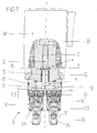
Fig. 1 zeigt ein Magnetdoppelventil D, z.B., einen Doppel-Ventileinsatz, zum Einbau in mit Strömungskanälen verbundene Aufnahmebohrungen eines Hydraulik-Ventilblocks 15, in welchem zwei in einer Ebene (in Fig. 1 in der Zeichenebene) nebeneinander liegende Ventilglieder V bestimmte Ventilfunktionen zu erfüllen haben. Die beiden Ventilglieder V werden durch einen gemeinsamen Magneten M, hier einem Kurzhubmagneten, betätigt, um gegen Federkraft aus Öffnungspositionen in ihre gezeigten Schließpositionen auf Sitze 14 verstellt und mit bestimmten Schließkräften gehalten zu werden.1 shows a magnetic double valve D, for example, a double valve insert, for installation in receiving bores of a
Der Magnet enthält einen Anker B und einen in einem festen Kernteil 1 verschiebbaren Ankerstößel 2, der ein Kraftübertragungsglied G mit der Magnetkraft beaufschlagt, um die beiden Ventilglieder V zu betätigen. Das Kraftübertragungsglied G ist T-förmig ausgebildet und mit einem Schaft 4 in einer Schiebeführung 3 im festen Kernteil 1 verschiebbar geführt. Der Schaft 4 ist mit einem Querteil 5 einstückig vereinigt.The magnet includes an armature B and an
Die Ventilglieder V sind Sitzventilglieder, die jeweils in einer Einsatzhülse 10 abgedichtet verschieblich geführt sind und Sitzen 14 gegenüberliegen. Die Einsatzhülsen 10 werden in Bohrungen des Blocks 15 mit den Ventilgliedem V abgedichtet eingebaut, wobei die Ventilglieder V von in Strömungskanälen 7 angeordneten Federn 6 in Abheberichtung von den Sitzen 14 beaufschlagt werden. Oberhalb der Einsatzhülsen 10 werden Einschraubhülsen 9 eingebracht, die die Einsatzhülsen 10 in den Einbaupositionen fixieren. In den Einschraubhülsen 9 sind Betätigungsstößel 11 für die Ventilglieder V abgedichtet geführt. Jeder Betätigungsstößel 11 ragt über die Oberseite der Einschraubhülse 9 hinaus und arbeitet mit dem Querteil 5 des Kraftübertragungsglieds G zusammen. Der Überstand der Betätigungsstößel 11 ist so gewählt, dass selbst bei erregtem Magneten und auf den Sitzen 14 gehaltenen Ventilgliedem V (Schließpositionen) die Unterseite des Querteils 5 des Kraftübertragungsgliedes G einen Abstand 13 zu den Oberseiten der Einschraubhülsen 9 einhält, und nicht auf Anschlag kommt. Der Magnet M kann über einen Zwischenring 12 mit einer Abdichtung 8 ebenfalls in den Block 15 eingesetzt sein. Die Schiebeführung 3 ist wenigstens eine Gleitlagerbuchse für den Schaft 4.The valve members V are seat valve members, which are guided in each case displaceably sealed in an
Alternativ könnte der Anker B direkt auf das Kraftübertragungsglied G einwirken.Alternatively, the armature B could act directly on the power transmission member G.
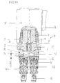
Das Doppelmagnetventil D in Fig. 1A enthält als die beiden Ventilglieder V ebenfalls Sitzventilglieder, deren jedes abwechselnd mit einem oberen und einem unteren Sitz zusammenarbeitet (zwei 3/2-Wegeventil-Funktionen). Die oberen Schließpositionen werden von den Federn 6 eingestellt, die unteren hingegen durch den einzigen Magneten M.The double solenoid valve D in Fig. 1A also contains, as the two valve members V, poppet valve members each of which alternately cooperates with upper and lower seats (two 3/2-way valve functions). The upper closing positions are set by the
In jeder Ausführungsform ist zwischen dem Anker B bzw. dem Ankerstößel 2 und dem Schaft 4 ein Kippgelenk K oberhalb der Schiebeführung 3 vorgesehen, das im Detail wie in den Fig. 2 - 18 gezeigt gestaltet sein kann.In each embodiment, a tilting joint K is provided above the sliding
Fig. 2 ist eine Detailschnittansicht zu Fig. 1 oder Fig. 1A zur Hervorhebung des Zusammenspiels zwischen dem Ankerstößel 2 und dem Schaft 4 des Kraftübertragungsglieds G im Kippgelenk K. Der Schaft 4 weist in dieser Ausführungsform eine in der Zeichenebene, d.h. der durch die Achsen der beiden Ventilglieder V in Fig. 1, Fig. 1A definierten Ebene, konvex gekrümmte Anlagefläche auf. Die Anlagefläche ist beispielsweise Teil einer Zylinderfläche mit einer Zylinderachse Y senkrecht zur Ebene der beiden Ventilglieder V, oder ist Teil einer Kugelfläche (Kugelzentrum Y). Der Ankerstößel 2 hat eine ebene Gegenfläche F, die senkrecht zur Stößelachse liegt. Der Schaft 4 ist mit einem radialen Sicherheitsspiel X in der Schiebeführung 3 aufgenommen. Das Sicherheitsspiel X beträgt beispielsweise etwa 2 % des Innendurchmessers der Schiebeführung 3. Bei einem Innendurchmesser von etwa 5 mm ist das gesamte Sicherheitsspiel ca. 0,1 mm.Fig. 2 is a detail sectional view of Fig. 1 or Fig. 1A for emphasizing the interaction between the
Die Gegenfläche F kontaktiert zum Übertragen der Magnetkraft die Anlagefläche A, so dass das Kippgelenk K gebildet ist. Solange der Schaft 4 koaxial zum Ankerstößel 2 ist, wird die Magnetkraft über das Kippgelenk K zentrisch übertragen. Die Anlagefläche A ist z.B. größer als die Gegenfläche F. Die beiden Flächen könnten auch gleich groß sein.The counter surface F contacted for transmitting the magnetic force, the contact surface A, so that the tilting joint K is formed. As long as the
In Fig. 3 ist die Anlagefläche A konvex gekrümmt (Zylinderfläche oder Kugelfläche), und ist auch die Gegenfläche F gleichsinnig gekrümmt, d.h. konkav (zylindrisch oder kugelig), gegebenenfalls mit größerem Krümmungsradius als die Anlagefläche A.In Fig. 3, the abutment surface A is convexly curved (cylindrical surface or spherical surface), and also the counter surface F is curved in the same direction, i. concave (cylindrical or spherical), possibly with a larger radius of curvature than the contact surface A.
In Fig. 4 ist die Anlagefläche A konkav gekrümmt (zylindrisch oder kugelig), während die Gegenfläche F konvex gekrümmt ist (zylindrisch oder kugelig).In Fig. 4, the abutment surface A is concavely curved (cylindrical or spherical), while the counter surface F is convexly curved (cylindrical or spherical).
In Fig. 5 sind sowohl die Anlagefläche A als auch die Gegenfläche F konvex gekrümmt (kugelig oder zylindrisch), d.h. gegensinnig konvex.In Fig. 5, both the abutment surface A and the counter surface F are convexly curved (spherical or cylindrical), i. in opposite directions convex.
Es ist nicht erforderlich, dass die ganze Gegenfläche F bzw. die ganze Anlagefläche A konvex oder konkav gekrümmt ist. Da das Sicherheitsspiel X in Relation zur Länge des Schafts 4 relativ klein ist, kann sich das Kraftübertragungsglied G ohnedies nur in einem beschränkten Ausmaß schräg stellen, so dass es ausreichen würde, jeweils nur einen mittigen Bereich der Anlagefläche A und/oder der Gegenfläche F konvex oder konkav zu formen.It is not necessary that the entire counter surface F or the entire contact surface A is curved convexly or concavely. Since the safety clearance X is relatively small in relation to the length of the
Die Fig. 6 und 7 verdeutlichen, was passiert, falls das in Fig. 1, Fig. 1A linke Ventilglied V einen höheren Widerstand leistet bzw. seine Schließposition früher einnimmt als das andere Ventilglied V. Der Schaft 4 kippt mit seiner Achse Z in Relation zu der durch den Ankerstößel 2 festgelegten Bewegungsachse Z' des Ankers im Uhrzeigersinn, und zwar im Rahmen des Sicherheitsspiels X. Dies bewirkt, dass entweder (Fig. 6) der Kontaktpunkt zum Übertragen der Magnetkraft im Kippgelenk K aus der zentrischen Lage von Fig. 2 etwas nach links verlagert und die Magnetkraft demzufolge etwas außermittig übertragen wird, oder (Fig. 7), die Anlagefläche A an der Gegenfläche F nach rechts gleitet, wenn der Schaft 4 kippt, und die Magnetkraft dann wiederum weitgehend zentrisch übertragen wird. Dadurch (Fig. 6, 7) wird eine Klemmung bzw. Hemmung des Schafts 4 in der Schiebeführung 3 vermieden. Beide Ventilglieder V werden zuverlässig in ihre Schließpositionen gebracht, selbst wenn die Ventilsitze in unterschiedlichen Höhenlagen liegen sollten.FIGS. 6 and 7 illustrate what happens if the left in Fig. 1, Fig. 1A valve member V makes a higher resistance or assumes its closed position earlier than the other valve member V. The
Wird der Magnet M entregt, dann drücken die Federn 7 die Ventilglieder in ihre Öffnungspositionen und über die Betätigungsstößel auch das Kraftübertragungsglied G, den Ankerstößel 2, und schließlich den Anker B zurück in die Ausgangsstellung. Dabei richtet sich das Kraftübertragungsglied G im Kippgelenk K selbsttätig wieder aus.When the magnet M is de-energized, the
In Fig. 8 wird das Kippgelenk K gebildet durch die ebene Gegenfläche F am Ankerstößel 2 und durch eine dieser gegenüber deutlich kleinere, z.B. ebene, Anlagefläche A', die zentrisch an einem mittig geformten Fortsatz D des Schafts 4 gebildet ist. In der gezeigten Kipplage des Schafts 4 wandert der Magnetkraft-Übertragungspunkt nur ganz wenig zur Seite. Der Fortsatz D könnte umgekehrt auch am Ankerstößel 2 geformt sein.In Fig. 8, the tilting joint K is formed by the flat counter surface F on the
In den Fig. 9 bis 18 ist im Kippgelenk eine Gelenkkugel G zwischen den Anlage- und Gegenflächen A, F platziert, wobei die Flächen in folgenden geometrischen Paarungen ausgebildet sein können: Eben/eben in Fig. 9; eben/konvex in Fig. 10; eben/konkav in Fig. 11; eben/eben mit einer oder zwei zentrischen Kugelsitzvertiefung(en) S in Fig. 12 und Fig. 18; konvex/konvex in Fig. 13; konkav/konvex in Fig. 14; eben/konvex oder eben/konkav mit einer zentrischen Kugelsitzvertiefung S in Fig. 15 oder Fig. 17; und konkav/konkav in Fig. 16.In FIGS. 9 to 18, in the tilting joint, a joint ball G is placed between the abutment and counter surfaces A, F, wherein the surfaces can be formed in the following geometric pairings: plane / planar in FIG. 9; plane / convex in Fig. 10; plane / concave in Fig. 11; even / just with one or two centric ball seat recesses (s) S in Fig. 12 and Fig. 18; convex / convex in Fig. 13; concave / convex in Fig. 14; plane / convex or even / concave with a centric ball seat recess S in Fig. 15 or Fig. 17; and concave / concave in FIG. 16.
Der Durchmesser der Gelenkkugel G entspricht in etwa dem Durchmesser des Ankerstößels 2 und/oder des Schafts 4. Die Gelenkkugel G könnte auch etwas kleiner und im Schaft 4 oder im Ankerstößel 2 versenkt und/oder verstemmt und/oder eingepresst fest positioniert sein, und so eine konvexe Fläche, ähnlich wie in Fig. 2, im Kippgelenk K bilden. The diameter of the joint ball G corresponds approximately to the diameter of the
Claims (13)
- Twin-solenoid valve (D) comprising two valve members (V) which are located side by side and are actuated in closing direction by a common solenoid (M) via a T-shaped force transmission member (G), the force transmission member (G) being guided by a stem (4) in a slide guidance (3), characterised In that a radial safety clearance (X) is provided between the slide guidance (3) and the stem (4) so that the force transmission member is able to take an inclined position in the slide guidance, and that at the side of the slide guidance (3) remote from the valve members (V) a tilt joint (K) is provided between the stem (4) of the force transmission member (G) and the armature (B) or a movably guided armature ram (2) of the solenoid (M).
- Twin-solenoid valve as in claim 1, characterised in that the tilt joint (K) includes directly or indirectly contacting first and second abutment surfaces and counter surfaces (A, F) at the armature (B) or at the armature ram (2) and at the stem (4), the surfaces (A, F) having one of the following geometrical pairings: planar/convex or concave/concave or convex/concave or convex/convex, and that the respective convex or concave abutment surface or counter surface (A, F) has at least a arc curvature within the plane in which both valve members (V) are situated side by side.
- Twin-solenoid valve as in claim 2, characterised in that the concave or convex arc curvature is a circular arc curvature the curvature centre (Y) of which being situated in the axis of the armature (B) or the armature ram (2) and/or of the stem (4), preferably as a part of a cylinder surface having a cylinder axis (Y) perpendicular to the plane of the valve members (V).
- Twin-solenoid valve as in claim 2, characterised in that the respective convex or concave abutment surface or counter surface (A, F) is formed as a part of a spherical surface having the centre (Y) in the axis of the armature (B) or the armature ram (2) and/or of the stem (4).
- Twin-solenoid valve as in claim 2, characterised in that in the geometrical pairing concave/convex the arc curvatures are made equal or that the convex arc curvature is stronger than the concave arc curvature.
- Twin-solenoid valve as in claim 1, characterised in that the tilt joint (K) is formed by a planar abutment surface (F) either at the stem (4) or at the armature (B) or at the armature ram (2) and a planar abutment surface (A') at a central projection (D) of the respective other component of the armature (B) or the armature ram (2) or the stem (4), the planar abutment surface (A') having a smaller diameter than the counter surface (F).
- Twin-solenoid valve as in claim 2, characterised in that a joint ball (G) is arranged within the tilt joint (K) between the abutment surface (A) and the counter surface (F).
- Twin-solenoid valve as in claim 7, characterised in that the joint ball (G) is provided between the abutment surface (F) and the counter surface (F) having one of the following geometrical pairings: planar/planar or planar/concave or planar/convex or concave/concave or concave/convex or convex/convex.
- Twin-solenoid valve as in claim 8, characterised in that at least one abutment surface or counter surface (A, F) of planar form comprises a central ball seat depression (S) having a diameter smaller than the diameter of the joint ball.
- Twin-solenoid valve as in at least one of claims 2 to 9, characterised in that the abutment surfaces and counter surfaces (A, F, A') have differing sizes.
- Twin-solenoid valve as in claim 1, characterised in that the slide guidance (3) is constituted by at least one plain bearing sleeve which is fitted in a receiving bore of a fixed core part (1) of the solenoid (M), that the force transmitting member (G) penetrates the plain bearing sleeve with a cylindrical stem (4), and that the safety clearance (X) is formed between the stem (4) and the plain bearing sleeve.
- Twin-solenoid valve as in claim 1, characterised in that the safety clearance (X) amounts to about 2% of the inner diameter of the slide guidance (3).
- Twin-solenoid valve as in claim 1, characterised in that each valve member (V) is arranged within an inserted sleeve (10), that a screw-in sleeve (9) is arranged above the inserted sleeve (10), that an actuating ram (11) is guided in the screw-in sleeve (9), that the force transmitting member (G) faces the screw-in sleeve (9) with a distance, and that the actuating ram projects beyond the screw-in sleeve (9) such that with the solenoid (M) energized and already reached closing position of the valve member (V) an intermediate space remains between the force transmitting member (G) and the screw-in sleeve (9).
Applications Claiming Priority (2)
| Application Number | Priority Date | Filing Date | Title |
|---|---|---|---|
| DE202004002432U | 2004-02-17 | ||
| DE200420002432 DE202004002432U1 (en) | 2004-02-17 | 2004-02-17 | Magnetic double valve |
Publications (2)
| Publication Number | Publication Date |
|---|---|
| EP1564465A1 EP1564465A1 (en) | 2005-08-17 |
| EP1564465B1 true EP1564465B1 (en) | 2007-01-17 |
Family
ID=34684171
Family Applications (1)
| Application Number | Title | Priority Date | Filing Date |
|---|---|---|---|
| EP20040026476 Not-in-force EP1564465B1 (en) | 2004-02-17 | 2004-11-08 | Electromagnetic dual valve |
Country Status (4)
| Country | Link |
|---|---|
| US (1) | US7219697B2 (en) |
| EP (1) | EP1564465B1 (en) |
| DE (2) | DE202004002432U1 (en) |
| ES (1) | ES2280882T3 (en) |
Families Citing this family (7)
| Publication number | Priority date | Publication date | Assignee | Title |
|---|---|---|---|---|
| DE102007037333A1 (en) | 2007-08-08 | 2009-02-26 | Daimler Ag | actuator |
| ES2428116T3 (en) | 2011-06-16 | 2013-11-06 | Hawe Hydraulik Se | Distributor valve |
| JP5848639B2 (en) * | 2012-03-07 | 2016-01-27 | 本田技研工業株式会社 | Valve device and failure detection device for hydraulic circuit |
| DE102012218593A1 (en) | 2012-10-12 | 2014-04-17 | Continental Automotive Gmbh | Valve for a pump |
| EP3016117B1 (en) | 2014-10-31 | 2017-12-06 | Husco Automotive Holdings LLC | Push pin actuator apparatus |
| DE102017200058A1 (en) * | 2017-01-04 | 2018-07-05 | Continental Teves Ag & Co. Ohg | Solenoid valve |
| DE102018215900A1 (en) * | 2018-09-19 | 2020-03-19 | Continental Teves Ag & Co. Ohg | Solenoid valve, in particular for slip-controlled motor vehicle brake systems |
Family Cites Families (6)
| Publication number | Priority date | Publication date | Assignee | Title |
|---|---|---|---|---|
| US1202895A (en) * | 1916-02-29 | 1916-10-31 | George M Rogers | Machine-oiler. |
| US2708561A (en) | 1952-02-18 | 1955-05-17 | Ap Controls Corp | Four-way valve |
| DE1085736B (en) | 1956-07-23 | 1960-07-21 | Roger Charles Dubois | Solenoid valve for fluids of all pressure ranges |
| US4494572A (en) * | 1982-09-30 | 1985-01-22 | Humphrey Products Company | Four-way poppet valve assembly |
| DE9109976U1 (en) | 1991-08-12 | 1991-10-10 | Heilmeier & Weinlein Fabrik Fuer Oel-Hydraulik Gmbh & Co Kg, 8000 Muenchen, De | |
| DE29905011U1 (en) | 1999-03-18 | 1999-06-02 | Heilmeier & Weinlein | Valve bank |
-
2004
- 2004-02-17 DE DE200420002432 patent/DE202004002432U1/en not_active Expired - Lifetime
- 2004-11-08 EP EP20040026476 patent/EP1564465B1/en not_active Not-in-force
- 2004-11-08 DE DE200450002669 patent/DE502004002669D1/en active Active
- 2004-11-08 ES ES04026476T patent/ES2280882T3/en active Active
-
2005
- 2005-02-10 US US11/055,337 patent/US7219697B2/en not_active Expired - Fee Related
Also Published As
| Publication number | Publication date |
|---|---|
| US20050178453A1 (en) | 2005-08-18 |
| EP1564465A1 (en) | 2005-08-17 |
| DE502004002669D1 (en) | 2007-03-08 |
| US7219697B2 (en) | 2007-05-22 |
| DE202004002432U1 (en) | 2005-07-07 |
| ES2280882T3 (en) | 2007-09-16 |
Similar Documents
| Publication | Publication Date | Title |
|---|---|---|
| DE2315425C2 (en) | Electromagnetically operated directional valve | |
| DE19655090C2 (en) | Electromagnetically operated directional valve | |
| EP2906815B1 (en) | Valve for a pump | |
| DE19936711A1 (en) | Solenoid valve, especially for hydraulic brake systems with slip control | |
| DE4244581A1 (en) | Electromagnetic actuator for valves and hydraulic applications - has fixed guide-pin with longitudinal and transverse fluid channels within sliding armature opposed by helical spring around piston | |
| DE19700980A1 (en) | Solenoid valve | |
| EP1591856A1 (en) | Pressure control valve | |
| DE10203886A1 (en) | pilot valve | |
| DE19716856B4 (en) | Unit for a hydraulic valve | |
| EP1564465B1 (en) | Electromagnetic dual valve | |
| EP0123938B1 (en) | Electromagnetically actuable valve | |
| EP1248173A1 (en) | Thermostatic mixer device | |
| DE69926384T2 (en) | ELECTROMAGNETIC CONTROL VALVE | |
| DE4301308C2 (en) | Hydraulic valve | |
| DE19607019A1 (en) | Electromagnetic operating device for IC engine gas changing valve | |
| DE19834786C2 (en) | Electromagnetic directional seat valve | |
| DE19509145B4 (en) | Directional seated valve | |
| EP2516906B1 (en) | Electromagnetic valve | |
| DE4111064A1 (en) | 3-2 Hydraulic directional control valve - has pair of spools in bore with angled connecting holes formed in each spool to provide interconnection across assembly for pressure balancing | |
| DE19618272A1 (en) | Electro=magnetically operated hydraulic valve reversible linkage | |
| DE3620242C2 (en) | ||
| EP2778437B1 (en) | Hydraulic valve | |
| DE19727183A1 (en) | Electromagnetically operated directional seat valve | |
| DE10029297A1 (en) | Valve for controling liquids has piezo actuator, dual piston hydraulic converter, valve closure element and spring element directly coupled to second piston of hydraulic converter | |
| EP0100330B1 (en) | Hydraulic control device |
Legal Events
| Date | Code | Title | Description |
|---|---|---|---|
| PUAI | Public reference made under article 153(3) epc to a published international application that has entered the european phase |
Free format text: ORIGINAL CODE: 0009012 |
|
| AK | Designated contracting states |
Kind code of ref document: A1 Designated state(s): AT BE BG CH CY CZ DE DK EE ES FI FR GB GR HU IE IS IT LI LU MC NL PL PT RO SE SI SK TR |
|
| AX | Request for extension of the european patent |
Extension state: AL HR LT LV MK YU |
|
| 17P | Request for examination filed |
Effective date: 20050914 |
|
| AKX | Designation fees paid |
Designated state(s): CH DE ES FR IT LI |
|
| GRAP | Despatch of communication of intention to grant a patent |
Free format text: ORIGINAL CODE: EPIDOSNIGR1 |
|
| GRAS | Grant fee paid |
Free format text: ORIGINAL CODE: EPIDOSNIGR3 |
|
| GRAA | (expected) grant |
Free format text: ORIGINAL CODE: 0009210 |
|
| AK | Designated contracting states |
Kind code of ref document: B1 Designated state(s): CH DE ES FR IT LI |
|
| REG | Reference to a national code |
Ref country code: CH Ref legal event code: NV Representative=s name: PATENTANWALTSBUERO JEAN HUNZIKER Ref country code: CH Ref legal event code: EP |
|
| REF | Corresponds to: |
Ref document number: 502004002669 Country of ref document: DE Date of ref document: 20070308 Kind code of ref document: P |
|
| ET | Fr: translation filed | ||
| REG | Reference to a national code |
Ref country code: ES Ref legal event code: FG2A Ref document number: 2280882 Country of ref document: ES Kind code of ref document: T3 |
|
| PLBE | No opposition filed within time limit |
Free format text: ORIGINAL CODE: 0009261 |
|
| STAA | Information on the status of an ep patent application or granted ep patent |
Free format text: STATUS: NO OPPOSITION FILED WITHIN TIME LIMIT |
|
| 26N | No opposition filed |
Effective date: 20071018 |
|
| PGFP | Annual fee paid to national office [announced via postgrant information from national office to epo] |
Ref country code: FR Payment date: 20131118 Year of fee payment: 10 Ref country code: ES Payment date: 20131119 Year of fee payment: 10 |
|
| REG | Reference to a national code |
Ref country code: FR Ref legal event code: ST Effective date: 20150731 |
|
| PG25 | Lapsed in a contracting state [announced via postgrant information from national office to epo] |
Ref country code: FR Free format text: LAPSE BECAUSE OF NON-PAYMENT OF DUE FEES Effective date: 20141201 |
|
| REG | Reference to a national code |
Ref country code: ES Ref legal event code: FD2A Effective date: 20151229 |
|
| PG25 | Lapsed in a contracting state [announced via postgrant information from national office to epo] |
Ref country code: ES Free format text: LAPSE BECAUSE OF NON-PAYMENT OF DUE FEES Effective date: 20141109 |
|
| PGFP | Annual fee paid to national office [announced via postgrant information from national office to epo] |
Ref country code: IT Payment date: 20151130 Year of fee payment: 12 |
|
| REG | Reference to a national code |
Ref country code: DE Ref legal event code: R082 Ref document number: 502004002669 Country of ref document: DE Representative=s name: GROSSE, SCHUMACHER, KNAUER, VON HIRSCHHAUSEN, DE |
|
| PG25 | Lapsed in a contracting state [announced via postgrant information from national office to epo] |
Ref country code: IT Free format text: LAPSE BECAUSE OF NON-PAYMENT OF DUE FEES Effective date: 20161108 |
|
| REG | Reference to a national code |
Ref country code: DE Ref legal event code: R082 Ref document number: 502004002669 Country of ref document: DE Representative=s name: GROSSE, SCHUMACHER, KNAUER, VON HIRSCHHAUSEN, DE Ref country code: DE Ref legal event code: R081 Ref document number: 502004002669 Country of ref document: DE Owner name: HAWE HYDRAULIK SE, DE Free format text: FORMER OWNER: HAWE HYDRAULIK GMBH & CO. KG, 81673 MUENCHEN, DE |
|
| REG | Reference to a national code |
Ref country code: CH Ref legal event code: PFA Owner name: HAWE HYDRAULIK SE, DE Free format text: FORMER OWNER: HAWE HYDRAULIK GMBH AND CO. KG, DE |
|
| REG | Reference to a national code |
Ref country code: DE Ref legal event code: R082 Ref document number: 502004002669 Country of ref document: DE Representative=s name: GROSSE, SCHUMACHER, KNAUER, VON HIRSCHHAUSEN, DE Ref country code: DE Ref legal event code: R081 Ref document number: 502004002669 Country of ref document: DE Owner name: HAWE HYDRAULIK SE, DE Free format text: FORMER OWNER: HAWE HYDRAULIK SE, 81673 MUENCHEN, DE |
|
| REG | Reference to a national code |
Ref country code: CH Ref legal event code: PFUS Owner name: HAWE HYDRAULIK SE, DE Free format text: FORMER OWNER: HAWE HYDRAULIK SE, DE |
|
| PGFP | Annual fee paid to national office [announced via postgrant information from national office to epo] |
Ref country code: DE Payment date: 20211119 Year of fee payment: 18 |
|
| PGFP | Annual fee paid to national office [announced via postgrant information from national office to epo] |
Ref country code: CH Payment date: 20211123 Year of fee payment: 18 |
|
| REG | Reference to a national code |
Ref country code: DE Ref legal event code: R119 Ref document number: 502004002669 Country of ref document: DE |
|
| P01 | Opt-out of the competence of the unified patent court (upc) registered |
Effective date: 20230523 |
|
| REG | Reference to a national code |
Ref country code: CH Ref legal event code: PL |
|
| PG25 | Lapsed in a contracting state [announced via postgrant information from national office to epo] |
Ref country code: LI Free format text: LAPSE BECAUSE OF NON-PAYMENT OF DUE FEES Effective date: 20221130 Ref country code: CH Free format text: LAPSE BECAUSE OF NON-PAYMENT OF DUE FEES Effective date: 20221130 |
|
| PG25 | Lapsed in a contracting state [announced via postgrant information from national office to epo] |
Ref country code: DE Free format text: LAPSE BECAUSE OF NON-PAYMENT OF DUE FEES Effective date: 20230601 |