EP1564465B1 - Soupape double électromagnétique - Google Patents
Soupape double électromagnétique Download PDFInfo
- Publication number
- EP1564465B1 EP1564465B1 EP20040026476 EP04026476A EP1564465B1 EP 1564465 B1 EP1564465 B1 EP 1564465B1 EP 20040026476 EP20040026476 EP 20040026476 EP 04026476 A EP04026476 A EP 04026476A EP 1564465 B1 EP1564465 B1 EP 1564465B1
- Authority
- EP
- European Patent Office
- Prior art keywords
- convex
- concave
- armature
- twin
- solenoid valve
- Prior art date
- Legal status (The legal status is an assumption and is not a legal conclusion. Google has not performed a legal analysis and makes no representation as to the accuracy of the status listed.)
- Expired - Lifetime
Links
Images


Classifications
-
- F—MECHANICAL ENGINEERING; LIGHTING; HEATING; WEAPONS; BLASTING
- F16—ENGINEERING ELEMENTS AND UNITS; GENERAL MEASURES FOR PRODUCING AND MAINTAINING EFFECTIVE FUNCTIONING OF MACHINES OR INSTALLATIONS; THERMAL INSULATION IN GENERAL
- F16K—VALVES; TAPS; COCKS; ACTUATING-FLOATS; DEVICES FOR VENTING OR AERATING
- F16K31/00—Actuating devices; Operating means; Releasing devices
- F16K31/02—Actuating devices; Operating means; Releasing devices electric; magnetic
- F16K31/06—Actuating devices; Operating means; Releasing devices electric; magnetic using a magnet, e.g. diaphragm valves, cutting off by means of a liquid
- F16K31/10—Actuating devices; Operating means; Releasing devices electric; magnetic using a magnet, e.g. diaphragm valves, cutting off by means of a liquid with additional mechanism between armature and closure member
-
- Y—GENERAL TAGGING OF NEW TECHNOLOGICAL DEVELOPMENTS; GENERAL TAGGING OF CROSS-SECTIONAL TECHNOLOGIES SPANNING OVER SEVERAL SECTIONS OF THE IPC; TECHNICAL SUBJECTS COVERED BY FORMER USPC CROSS-REFERENCE ART COLLECTIONS [XRACs] AND DIGESTS
- Y10—TECHNICAL SUBJECTS COVERED BY FORMER USPC
- Y10T—TECHNICAL SUBJECTS COVERED BY FORMER US CLASSIFICATION
- Y10T137/00—Fluid handling
- Y10T137/8593—Systems
- Y10T137/877—With flow control means for branched passages
- Y10T137/87708—With common valve operator
- Y10T137/87772—With electrical actuation
Definitions
- solenoid double valves are designed for example as a valve core assembly, which is used in a flow path containing body in leading to the flow paths receiving bores, for example, to control certain valve functions by means of the two valve members. Since the common magnet has to actuate both valve members in the closing direction against valve seats, and because of unavoidable manufacturing tolerances, the actuating strokes may be different up to the closing positions or the opposing forces of the valve members, the sliding fit of the force transmission member is selected as narrow as possible in the sliding guide so that the Sliding guide a tilting of the power transmission member largely excludes.
- the invention has for its object to provide a magnetic double valve of the type mentioned with improved reliability and simple design, in particular a magnetic double valve having a short-stroke magnet for adjusting the two valve members in their closed positions.
- This mating may be: flat / convex or concave / concave or convex / concave or convex / convex, with the respective convex or concave surface having at least one arc of curvature in the plane in which the two valve members are juxtaposed.
- the concave or convex arc curvature may be a circular arc curvature, either part of a cylindrical surface having a cylinder axis perpendicular to the plane of the valve members, or part of a spherical surface having the center of the ball in the axis of the armature, the armature tappet and / or the shaft.
- the formation of these surfaces is manufacturing technology simple.
- a joint ball is arranged in the tilting joint between the contact surfaces, which the mobility in tilting joint also comes in oblique position of the power transmission member to good.
- the following geometric pairings of the first and second abutment surfaces are expedient: flat / flat or even / concave or planar / convex or concave / concave or concave / convex or convex / convex.
- the first and second contact surfaces can be sized differently.
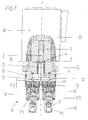
- FIG. 1 shows a magnetic double valve D, for example, a double valve insert, for installation in receiving bores of a hydraulic valve block 15 connected to flow channels, in which two valve elements V lying next to one another in a plane (in FIG. 1 in the drawing plane) have certain valve functions have fulfilled.
- the two valve members V are actuated by a common magnet M, here a Kurzhubmagneten to be adjusted against spring force from opening positions in their closed positions shown on seats 14 and held with certain closing forces.
Landscapes
- Engineering & Computer Science (AREA)
- General Engineering & Computer Science (AREA)
- Mechanical Engineering (AREA)
- Magnetically Actuated Valves (AREA)
Claims (13)
- Soupape double électromagnétique (D) comprenant deux organes de soupape (V) juxtaposés, actionnables dans la direction de fermeture contre une force de ressorts (6) par un aimant commun (M) par l'intermédiaire d'un organe de trans-mission des forces en T (G), guidé par une tige (4) dans un guide de coulisse (3), caractérisée en ce qu'un jeu de sécurité radial (X) est prévu entre le guide de coulisse (3) et la tige (4), de sorte que l'organe de transmission des forces peut se placer en oblique dans le guide de coulisse (3), et qu'une articulation basculante (K) est prévue sur le côté, opposé aux organes de soupape (V), du guide de coulisse (3) entre la tige (4) de l'organe de transmission des forces (G) et l'induit (B) ou un poussoir d'induit (2) guidé mobile de l'aimant (M).
- Soupape double électromagnétique suivant la revendication 1, caractérisée en ce que l'articulation basculante (K) comprend, sur l'induit (B) ou sur le poussoir d'induit (2) et sur la tige (4), une première et une seconde surface de contact (A, F) directement ou indirectement au contact l'une de l'autre, dans l'appariement géométrique suivant : plan/convexe ou concave/concave ou convexe/concave ou convexe/convexe, la surface de contact respectivement convexe ou concave (A, F) présentant au moins une courbure en arc dans le plan, dans lequel se situent en juxtaposition les deux organes de soupape (V).
- Soupape double électromagnétique suivant la revendication 2, caractérisée en ce que la courbure en arc concave ou convexe est une courbure en arc de cercle, dont le centre de courbure (Y) se situe dans l'axe de l'induit (B) et/ou du poussoir d'induit (2) et/ou de la tige (4), est de préférence une partie d'une surface cylindrique avec un axe de cylindre (Y) perpendiculaire au plan des organes de soupape (V).
- Soupape double électromagnétique suivant la revendication 2, caractérisée en ce que la surface de contact respectivement convexe ou concave (A, F) est une partie d'une surface sphérique avec le centre (Y) dans l'axe de l'induit (B) ou du poussoir d'induit (2) et/ou de la tige (4).
- Soupape double électromagnétique suivant la revendication 2, caractérisée en ce que, dans l'appariement géométrique concave/convexe, les courbures en arc sont égales ou la courbure en arc convexe est plus forte que la courbure en arc concave.
- Soupape double électromagnétique suivant la revendication 1, caractérisée en ce que l'articulation basculante (K) est formée d'une surface de contact plane (F) sur la tige (4) ou sur l'induit (B) ou sur le poussoir d'induit (2) et d'une surface de contact (A') également plane, d'un diamètre plus petit que celui de la surface antagoniste (F), sur un prolongement centré (D) de l'autre composant respectif de l'induit (B) ou du poussoir d'induit (2) ou de la tige (4).
- Soupape double électromagnétique suivant la revendication 2, caractérisée en ce qu'une bille d'articulation (G) est disposée dans l'articulation basculante (K) entre la surface de contact et la surface antagoniste (A, F).
- Soupape double électromagnétique suivant la revendication 7, caractérisée en ce que les surfaces de contact (A, F), qui renferment entre elles la bille d'articulation (G), sont configurées dans l'appariement géométrique suivant : plan/plan ou plan/concave ou plan/convexe ou concave/concave ou concave/convexe ou convexe/convexe.
- Soupape double électromagnétique suivant la revendication 8, caractérisée en ce qu'au moins une surface de contact (A, F) de configuration plane comporte un creux de siège sphérique centré (S) de diamètre plus petit que le diamètre de la bille.
- Soupape double électromagnétique suivant l'une au moins des revendications 2 à 9, caractérisée en ce que les surfaces de contact (A', A, F) sont de dimensions différentes.
- Soupape double électromagnétique suivant la revendication 1, caractérisée en ce que le guide de coulisse (3) est au moins un coussinet lisse, qui se situe dans un trou de réception d'une partie de noyau fixe (1) de l'aimant (M), que l'organe de transmission des forces (G) traverse par une tige cylindrique (4) le coussinet lisse, et que le jeu de sécurité (X) est formé entre la tige (4) et le coussinet lisse.
- Soupape double électromagnétique suivant la revendication 1, caractérisée en ce que le jeu de sécurité (X) est d'environ 2% du diamètre intérieur du guide de coulisse (3).
- Soupape double électromagnétique suivant la revendication 1, caractérisée en ce que chaque organe de soupape (V) est disposé dans une douille de réduction (10), qu'un manchon fileté (9), dans lequel est guidé un poussoir d'actionnement (11), est prévu au-dessus de la douille de réduction (10), que l'organe de transmission des forces (G) est en vis-à-vis du manchon fileté (9) avec un écartement (13), et que le poussoir d'actionnement (11) dépasse suffisamment du manchon fileté (9) pour qu'un espace intermédiaire subsiste entre l'organe de transmission des forces (G) et le manchon fileté lorsque l'aimant (M) est excité et que la position de fermeture de l'organe de soupape (V) est atteinte.
Applications Claiming Priority (2)
| Application Number | Priority Date | Filing Date | Title |
|---|---|---|---|
| DE202004002432U | 2004-02-17 | ||
| DE200420002432 DE202004002432U1 (de) | 2004-02-17 | 2004-02-17 | Magnetdoppelventil |
Publications (2)
| Publication Number | Publication Date |
|---|---|
| EP1564465A1 EP1564465A1 (fr) | 2005-08-17 |
| EP1564465B1 true EP1564465B1 (fr) | 2007-01-17 |
Family
ID=34684171
Family Applications (1)
| Application Number | Title | Priority Date | Filing Date |
|---|---|---|---|
| EP20040026476 Expired - Lifetime EP1564465B1 (fr) | 2004-02-17 | 2004-11-08 | Soupape double électromagnétique |
Country Status (4)
| Country | Link |
|---|---|
| US (1) | US7219697B2 (fr) |
| EP (1) | EP1564465B1 (fr) |
| DE (2) | DE202004002432U1 (fr) |
| ES (1) | ES2280882T3 (fr) |
Families Citing this family (8)
| Publication number | Priority date | Publication date | Assignee | Title |
|---|---|---|---|---|
| DE102007037333A1 (de) | 2007-08-08 | 2009-02-26 | Daimler Ag | Betätigungsvorrichtung |
| ES2428116T3 (es) | 2011-06-16 | 2013-11-06 | Hawe Hydraulik Se | Válvula distribuidora |
| JP5848639B2 (ja) * | 2012-03-07 | 2016-01-27 | 本田技研工業株式会社 | バルブ装置、及び油圧回路の故障検出装置 |
| DE102012218593A1 (de) | 2012-10-12 | 2014-04-17 | Continental Automotive Gmbh | Ventil für eine Pumpe |
| US9583249B2 (en) | 2014-10-31 | 2017-02-28 | Husco Automotive Holdings Llc | Methods and systems for push pin actuator |
| DE102017200058A1 (de) * | 2017-01-04 | 2018-07-05 | Continental Teves Ag & Co. Ohg | Elektromagnetventil |
| DE102018215900A1 (de) * | 2018-09-19 | 2020-03-19 | Continental Teves Ag & Co. Ohg | Elektromagnetventil, insbesondere für schlupfgeregelte Kraftfahrzeugbremsanlagen |
| EP4450826A1 (fr) * | 2023-04-21 | 2024-10-23 | Hamilton Sundstrand Corporation | Ensemble servo-soupape à étage unique |
Family Cites Families (6)
| Publication number | Priority date | Publication date | Assignee | Title |
|---|---|---|---|---|
| US1202895A (en) * | 1916-02-29 | 1916-10-31 | George M Rogers | Machine-oiler. |
| US2708561A (en) | 1952-02-18 | 1955-05-17 | Ap Controls Corp | Four-way valve |
| DE1085736B (de) | 1956-07-23 | 1960-07-21 | Roger Charles Dubois | Magnetventil fuer Fluessigkeiten aller Druckbereiche |
| US4494572A (en) * | 1982-09-30 | 1985-01-22 | Humphrey Products Company | Four-way poppet valve assembly |
| DE9109976U1 (de) | 1991-08-12 | 1991-10-10 | Heilmeier & Weinlein Fabrik für Oel-Hydraulik GmbH & Co KG, 8000 München | Magnetventilvorrichtung |
| DE29905011U1 (de) | 1999-03-18 | 1999-06-02 | Heilmeier & Weinlein Fabrik für Oel-Hydraulik GmbH & Co KG, 81673 München | Ventilverband |
-
2004
- 2004-02-17 DE DE200420002432 patent/DE202004002432U1/de not_active Expired - Lifetime
- 2004-11-08 EP EP20040026476 patent/EP1564465B1/fr not_active Expired - Lifetime
- 2004-11-08 ES ES04026476T patent/ES2280882T3/es not_active Expired - Lifetime
- 2004-11-08 DE DE200450002669 patent/DE502004002669D1/de not_active Expired - Lifetime
-
2005
- 2005-02-10 US US11/055,337 patent/US7219697B2/en not_active Expired - Fee Related
Also Published As
| Publication number | Publication date |
|---|---|
| EP1564465A1 (fr) | 2005-08-17 |
| ES2280882T3 (es) | 2007-09-16 |
| US20050178453A1 (en) | 2005-08-18 |
| DE502004002669D1 (de) | 2007-03-08 |
| DE202004002432U1 (de) | 2005-07-07 |
| US7219697B2 (en) | 2007-05-22 |
Similar Documents
| Publication | Publication Date | Title |
|---|---|---|
| DE2315425C2 (de) | Elektromagnetisch betätigtes Wegeventil | |
| DE19655090C2 (de) | Elektromagnetisch betätigtes Wegeventil | |
| EP2906815B1 (fr) | Soupape pour une pompe | |
| EP1564465B1 (fr) | Soupape double électromagnétique | |
| DE10203886A1 (de) | Vorsteuerventil | |
| DE19716856B4 (de) | Baueinheit für ein Hydraulikventil | |
| EP1591856A1 (fr) | Vanne de régulation de pression | |
| DE69401263T3 (de) | Proportionales elektromagnetisch gesteuertes druckluftventil | |
| EP1248173A1 (fr) | Mélangeur thermostatic | |
| EP0123938B1 (fr) | Valve à commande électromagnétique | |
| DE3439378A1 (de) | Druckregelventil sowie verfahren zur herstellung eines solchen druckregelventils | |
| DE102004015661A1 (de) | Elektropneumatisches Ventil, insbesondere Vorsteuerventil für ein pneumatisches Wegeventil | |
| DE4301308C2 (de) | Hydraulik-Ventil | |
| DE19607019A1 (de) | Vorrichtung zur elektromagnetischen Betätigung eines Gaswechselventiles für Verbrennungsmotoren | |
| EP2516906B1 (fr) | Vanne électromagnétique | |
| DE19834786C2 (de) | Elektromagnetisches Wegesitzventil | |
| DE19509145B4 (de) | Wegesitzventil | |
| DE4111064A1 (de) | Wegeventil mit zwei beabstandeten ventilkoerpern | |
| DE20116920U1 (de) | Sitzventil für den Differentialzylinder eines elektrischen Trennschalters | |
| DE19618272A1 (de) | Magnetventil | |
| DE3414548C2 (fr) | ||
| DE19727183A1 (de) | Wege-Sitzventil, insbesondere elektromagnetisch betätigbares Wege-Sitzventil | |
| EP2778437B1 (fr) | Soupape hydraulique | |
| EP0100330B1 (fr) | Dispositif de commande hydraulique | |
| DE2315424A1 (de) | Elektromagnetisch betaetigtes wegeventil |
Legal Events
| Date | Code | Title | Description |
|---|---|---|---|
| PUAI | Public reference made under article 153(3) epc to a published international application that has entered the european phase |
Free format text: ORIGINAL CODE: 0009012 |
|
| AK | Designated contracting states |
Kind code of ref document: A1 Designated state(s): AT BE BG CH CY CZ DE DK EE ES FI FR GB GR HU IE IS IT LI LU MC NL PL PT RO SE SI SK TR |
|
| AX | Request for extension of the european patent |
Extension state: AL HR LT LV MK YU |
|
| 17P | Request for examination filed |
Effective date: 20050914 |
|
| AKX | Designation fees paid |
Designated state(s): CH DE ES FR IT LI |
|
| GRAP | Despatch of communication of intention to grant a patent |
Free format text: ORIGINAL CODE: EPIDOSNIGR1 |
|
| GRAS | Grant fee paid |
Free format text: ORIGINAL CODE: EPIDOSNIGR3 |
|
| GRAA | (expected) grant |
Free format text: ORIGINAL CODE: 0009210 |
|
| AK | Designated contracting states |
Kind code of ref document: B1 Designated state(s): CH DE ES FR IT LI |
|
| REG | Reference to a national code |
Ref country code: CH Ref legal event code: NV Representative=s name: PATENTANWALTSBUERO JEAN HUNZIKER Ref country code: CH Ref legal event code: EP |
|
| REF | Corresponds to: |
Ref document number: 502004002669 Country of ref document: DE Date of ref document: 20070308 Kind code of ref document: P |
|
| ET | Fr: translation filed | ||
| REG | Reference to a national code |
Ref country code: ES Ref legal event code: FG2A Ref document number: 2280882 Country of ref document: ES Kind code of ref document: T3 |
|
| PLBE | No opposition filed within time limit |
Free format text: ORIGINAL CODE: 0009261 |
|
| STAA | Information on the status of an ep patent application or granted ep patent |
Free format text: STATUS: NO OPPOSITION FILED WITHIN TIME LIMIT |
|
| 26N | No opposition filed |
Effective date: 20071018 |
|
| PGFP | Annual fee paid to national office [announced via postgrant information from national office to epo] |
Ref country code: FR Payment date: 20131118 Year of fee payment: 10 Ref country code: ES Payment date: 20131119 Year of fee payment: 10 |
|
| REG | Reference to a national code |
Ref country code: FR Ref legal event code: ST Effective date: 20150731 |
|
| PG25 | Lapsed in a contracting state [announced via postgrant information from national office to epo] |
Ref country code: FR Free format text: LAPSE BECAUSE OF NON-PAYMENT OF DUE FEES Effective date: 20141201 |
|
| REG | Reference to a national code |
Ref country code: ES Ref legal event code: FD2A Effective date: 20151229 |
|
| PG25 | Lapsed in a contracting state [announced via postgrant information from national office to epo] |
Ref country code: ES Free format text: LAPSE BECAUSE OF NON-PAYMENT OF DUE FEES Effective date: 20141109 |
|
| PGFP | Annual fee paid to national office [announced via postgrant information from national office to epo] |
Ref country code: IT Payment date: 20151130 Year of fee payment: 12 |
|
| REG | Reference to a national code |
Ref country code: DE Ref legal event code: R082 Ref document number: 502004002669 Country of ref document: DE Representative=s name: GROSSE, SCHUMACHER, KNAUER, VON HIRSCHHAUSEN, DE |
|
| PG25 | Lapsed in a contracting state [announced via postgrant information from national office to epo] |
Ref country code: IT Free format text: LAPSE BECAUSE OF NON-PAYMENT OF DUE FEES Effective date: 20161108 |
|
| REG | Reference to a national code |
Ref country code: DE Ref legal event code: R082 Ref document number: 502004002669 Country of ref document: DE Representative=s name: GROSSE, SCHUMACHER, KNAUER, VON HIRSCHHAUSEN, DE Ref country code: DE Ref legal event code: R081 Ref document number: 502004002669 Country of ref document: DE Owner name: HAWE HYDRAULIK SE, DE Free format text: FORMER OWNER: HAWE HYDRAULIK GMBH & CO. KG, 81673 MUENCHEN, DE |
|
| REG | Reference to a national code |
Ref country code: CH Ref legal event code: PFA Owner name: HAWE HYDRAULIK SE, DE Free format text: FORMER OWNER: HAWE HYDRAULIK GMBH AND CO. KG, DE |
|
| REG | Reference to a national code |
Ref country code: DE Ref legal event code: R082 Ref document number: 502004002669 Country of ref document: DE Representative=s name: GROSSE, SCHUMACHER, KNAUER, VON HIRSCHHAUSEN, DE Ref country code: DE Ref legal event code: R081 Ref document number: 502004002669 Country of ref document: DE Owner name: HAWE HYDRAULIK SE, DE Free format text: FORMER OWNER: HAWE HYDRAULIK SE, 81673 MUENCHEN, DE |
|
| REG | Reference to a national code |
Ref country code: CH Ref legal event code: PFUS Owner name: HAWE HYDRAULIK SE, DE Free format text: FORMER OWNER: HAWE HYDRAULIK SE, DE |
|
| PGFP | Annual fee paid to national office [announced via postgrant information from national office to epo] |
Ref country code: DE Payment date: 20211119 Year of fee payment: 18 |
|
| PGFP | Annual fee paid to national office [announced via postgrant information from national office to epo] |
Ref country code: CH Payment date: 20211123 Year of fee payment: 18 |
|
| REG | Reference to a national code |
Ref country code: DE Ref legal event code: R119 Ref document number: 502004002669 Country of ref document: DE |
|
| P01 | Opt-out of the competence of the unified patent court (upc) registered |
Effective date: 20230523 |
|
| REG | Reference to a national code |
Ref country code: CH Ref legal event code: PL |
|
| PG25 | Lapsed in a contracting state [announced via postgrant information from national office to epo] |
Ref country code: LI Free format text: LAPSE BECAUSE OF NON-PAYMENT OF DUE FEES Effective date: 20221130 Ref country code: CH Free format text: LAPSE BECAUSE OF NON-PAYMENT OF DUE FEES Effective date: 20221130 |
|
| PG25 | Lapsed in a contracting state [announced via postgrant information from national office to epo] |
Ref country code: DE Free format text: LAPSE BECAUSE OF NON-PAYMENT OF DUE FEES Effective date: 20230601 |