EP1564448B1 - Méthode de détermination de la position d'un système d'actionnement d'une transmission - Google Patents
Méthode de détermination de la position d'un système d'actionnement d'une transmission Download PDFInfo
- Publication number
- EP1564448B1 EP1564448B1 EP05001868A EP05001868A EP1564448B1 EP 1564448 B1 EP1564448 B1 EP 1564448B1 EP 05001868 A EP05001868 A EP 05001868A EP 05001868 A EP05001868 A EP 05001868A EP 1564448 B1 EP1564448 B1 EP 1564448B1
- Authority
- EP
- European Patent Office
- Prior art keywords
- actuating
- actuating element
- movement
- force
- range
- Prior art date
- Legal status (The legal status is an assumption and is not a legal conclusion. Google has not performed a legal analysis and makes no representation as to the accuracy of the status listed.)
- Expired - Lifetime
Links
- 238000000034 method Methods 0.000 title claims description 52
- 230000005540 biological transmission Effects 0.000 title claims description 40
- 230000033001 locomotion Effects 0.000 claims abstract description 76
- 230000009467 reduction Effects 0.000 claims description 8
- 230000007935 neutral effect Effects 0.000 abstract description 5
- 230000003247 decreasing effect Effects 0.000 description 6
- 230000009471 action Effects 0.000 description 5
- 230000008569 process Effects 0.000 description 5
- 238000013459 approach Methods 0.000 description 4
- 238000006073 displacement reaction Methods 0.000 description 4
- 238000005381 potential energy Methods 0.000 description 4
- 238000004519 manufacturing process Methods 0.000 description 3
- 230000036316 preload Effects 0.000 description 3
- 230000003068 static effect Effects 0.000 description 2
- 230000007704 transition Effects 0.000 description 2
- 230000003213 activating effect Effects 0.000 description 1
- 230000004913 activation Effects 0.000 description 1
- WYTGDNHDOZPMIW-RCBQFDQVSA-N alstonine Natural products C1=CC2=C3C=CC=CC3=NC2=C2N1C[C@H]1[C@H](C)OC=C(C(=O)OC)[C@H]1C2 WYTGDNHDOZPMIW-RCBQFDQVSA-N 0.000 description 1
- 230000008859 change Effects 0.000 description 1
- 238000010276 construction Methods 0.000 description 1
- 125000004122 cyclic group Chemical group 0.000 description 1
- 230000001351 cycling effect Effects 0.000 description 1
- 230000002950 deficient Effects 0.000 description 1
- 238000013461 design Methods 0.000 description 1
- 238000001514 detection method Methods 0.000 description 1
- 238000010586 diagram Methods 0.000 description 1
- 230000000694 effects Effects 0.000 description 1
- 230000005284 excitation Effects 0.000 description 1
- 238000002474 experimental method Methods 0.000 description 1
- 230000006870 function Effects 0.000 description 1
- 238000005259 measurement Methods 0.000 description 1
- 230000007246 mechanism Effects 0.000 description 1
- 238000012360 testing method Methods 0.000 description 1
- 238000012549 training Methods 0.000 description 1
Images


Classifications
-
- F—MECHANICAL ENGINEERING; LIGHTING; HEATING; WEAPONS; BLASTING
- F16—ENGINEERING ELEMENTS AND UNITS; GENERAL MEASURES FOR PRODUCING AND MAINTAINING EFFECTIVE FUNCTIONING OF MACHINES OR INSTALLATIONS; THERMAL INSULATION IN GENERAL
- F16H—GEARING
- F16H59/00—Control inputs to control units of change-speed- or reversing-gearings for conveying rotary motion
- F16H59/02—Selector apparatus
- F16H59/08—Range selector apparatus
- F16H59/10—Range selector apparatus comprising levers
-
- F—MECHANICAL ENGINEERING; LIGHTING; HEATING; WEAPONS; BLASTING
- F16—ENGINEERING ELEMENTS AND UNITS; GENERAL MEASURES FOR PRODUCING AND MAINTAINING EFFECTIVE FUNCTIONING OF MACHINES OR INSTALLATIONS; THERMAL INSULATION IN GENERAL
- F16H—GEARING
- F16H61/00—Control functions within control units of change-speed- or reversing-gearings for conveying rotary motion ; Control of exclusively fluid gearing, friction gearing, gearings with endless flexible members or other particular types of gearing
- F16H61/24—Providing feel, e.g. to enable selection
-
- F—MECHANICAL ENGINEERING; LIGHTING; HEATING; WEAPONS; BLASTING
- F16—ENGINEERING ELEMENTS AND UNITS; GENERAL MEASURES FOR PRODUCING AND MAINTAINING EFFECTIVE FUNCTIONING OF MACHINES OR INSTALLATIONS; THERMAL INSULATION IN GENERAL
- F16H—GEARING
- F16H63/00—Control outputs from the control unit to change-speed- or reversing-gearings for conveying rotary motion or to other devices than the final output mechanism
- F16H63/02—Final output mechanisms therefor; Actuating means for the final output mechanisms
- F16H63/30—Constructional features of the final output mechanisms
- F16H63/38—Detents
-
- F—MECHANICAL ENGINEERING; LIGHTING; HEATING; WEAPONS; BLASTING
- F16—ENGINEERING ELEMENTS AND UNITS; GENERAL MEASURES FOR PRODUCING AND MAINTAINING EFFECTIVE FUNCTIONING OF MACHINES OR INSTALLATIONS; THERMAL INSULATION IN GENERAL
- F16H—GEARING
- F16H61/00—Control functions within control units of change-speed- or reversing-gearings for conveying rotary motion ; Control of exclusively fluid gearing, friction gearing, gearings with endless flexible members or other particular types of gearing
- F16H61/24—Providing feel, e.g. to enable selection
- F16H2061/241—Actuators providing feel or simulating a shift gate, i.e. with active force generation for providing counter forces for feed back
-
- F—MECHANICAL ENGINEERING; LIGHTING; HEATING; WEAPONS; BLASTING
- F16—ENGINEERING ELEMENTS AND UNITS; GENERAL MEASURES FOR PRODUCING AND MAINTAINING EFFECTIVE FUNCTIONING OF MACHINES OR INSTALLATIONS; THERMAL INSULATION IN GENERAL
- F16H—GEARING
- F16H61/00—Control functions within control units of change-speed- or reversing-gearings for conveying rotary motion ; Control of exclusively fluid gearing, friction gearing, gearings with endless flexible members or other particular types of gearing
- F16H61/26—Generation or transmission of movements for final actuating mechanisms
- F16H61/28—Generation or transmission of movements for final actuating mechanisms with at least one movement of the final actuating mechanism being caused by a non-mechanical force, e.g. power-assisted
- F16H2061/283—Adjustment or calibration of actuator positions, e.g. neutral position
-
- F—MECHANICAL ENGINEERING; LIGHTING; HEATING; WEAPONS; BLASTING
- F16—ENGINEERING ELEMENTS AND UNITS; GENERAL MEASURES FOR PRODUCING AND MAINTAINING EFFECTIVE FUNCTIONING OF MACHINES OR INSTALLATIONS; THERMAL INSULATION IN GENERAL
- F16H—GEARING
- F16H2342/00—Calibrating
Definitions
- the present invention relates to methods for determining an actuation position in a transmission actuation system, according to the preambles of claims 1 and 13, as disclosed in US-A-2002088681.
- an actuator arrangement In automated or automatic transmissions in motor vehicles, an actuator arrangement is generally provided, the activation of which leads to gears being engaged or designed in the transmission.
- the actuators In automated manual transmissions, the actuators generally cause either a lane selection movement to occur, by which one of a plurality of shift lanes is selected, with each shift lane providing at least one gear to be selected in a gear select mode.
- the actuation of the actuator assembly In automatic transmissions, the actuation of the actuator assembly generally has the consequence that one of the selection ranges, for example P, R, N, D, is selected and, accordingly, the automatic transmission then operates in the selected mode.
- an actuator is then generally provided which is moved under the action of the actuator assembly to perform the various modes of motion.
- This actuator is then, for example, in association with a respective shift gate or provided in a shift gate gear ratios in certain operating positions positionable, wherein each of these operating positions coincide with a predetermined state of the transmission.
- the neutral position ie the position lying between two selectable gear ratios, be such a predetermined operating position, of course, such a position can be an actuating position in which then a respective gear is engaged.
- the actuating element in association with the various options P, R, N, D, the actuating element can then occupy a specific actuating position.
- this object is achieved by a method having the features of claim 1.
- the actuator is assigned a position detection arrangement to detect its position to then, when it is determined that a certain operating position is present to be able to provide a link between the operating position and the then existing output of this arrangement.
- the actuating element is acted upon in such a way that it can not be moved out of the pretensioning area. In this way it is ensured that from the beginning the reciprocating motion of the actuating element is limited to the effective range of the biasing arrangement assigned to a specific actuating position.
- the measure c) comprises reducing the force acting on the actuator actuating forces and / or the deflection in each case after a period of reciprocation of the actuating element.
- the reduction of the actuating forces acting on the actuating element or the deflection of the actuating element can take place in predetermined steps. These steps or the step size can each be adapted to specific transmission systems or actuating systems or also the configuration of the biasing arrangement. Furthermore, it can be predetermined that, for example, when approaching the desired actuating position with the reduction of the actuating forces or the deflection, the step size is changed, for example reduced, in order to obtain an even more precise limitation of the actuating position.
- the actuating element is brought into a position which corresponds to an assumed position of the actuating position. Since basically the structural design of a transmission or the associated transmission actuating system is known, afflicted with certain inaccuracies, in principle, the Location of the actuating positions, for example in a certain rotation angle range or a specific linear displacement range, known. This knowledge can be used in order to be able to perform as quickly as possible the finding of the desired operating position or the determination of the exact position of this sought operating position in this way.
- the biasing arrangement may comprise a latching arrangement.
- actuation systems or transmissions in which follow in a motion mode, for example, a linear motion mode or a rotary motion mode, multiple actuation position in the range of motion on each other to ensure that all of these operating positions can be precisely specified and subsequently approached in gear operation, it is proposed that the measures a) - d) are carried out successively to determine several operating positions.
- the object mentioned at the outset is achieved by a method for determining an actuation position in a transmission actuation system, which actuation system comprises an actuation element which can be brought into a plurality of actuation positions by an actuator arrangement, wherein the actuation element is assigned a preload arrangement for at least one of the actuation positions is, which, when the actuating element has a lying in a biasing region to the actuating position position biasing the actuating element in the direction of actuation position, which method has the measures defined in claim 13.
- the procedure is thus that initially the actuating element is moved back and forth at the beginning of the process so that the movement end positions are reached, that is, reciprocated to the maximum extent possible, with the action range of the preload arrangement being involved in this back and forth movement , which is assigned to a sought-after operating position, can be exceeded.
- a part of a transmission operating system can be seen.
- This part shown in Figure 1 is a so-called shift finger 10 which is carried on a shift shaft, not shown, and together with this shift shaft about a rotation axis A is rotatable or pivotable.
- the selection of a shift gate for example, by this rotational movement or pivoting movement of the shift finger 10, wherein when a certain shift gate is selected by shifting the shift shaft together with the shift finger of one of the gears present in this shift gate off - or can be inserted.
- When used in an automatic transmission can be done by moving the shift finger 10 in one of four possible rotational positions in the transmission selection of one of the four states P, R, N and D.
- Each of these possible selection positions or shift positions in an automated manual transmission corresponds to a specific actuation position of the transmission actuation system or also of the shift finger 10 which can be interpreted as an actuation element, for example, as illustrated in FIG. the position of which, for example, rotational position and / or linear displacement position, detected and can enter a corresponding signal in a drive device for an actuator assembly, not shown, of the transmission operating system.
- the actuation system 10 can be brought precisely into a predetermined position, for example, to approach one of the four selection states P, R, N, D.
- the transmission operating system for example, directly in the shift finger 10 in the Fig. 1 schematically indicated biasing assembly 14 be assigned.
- This may include a biasing spring 16, which presses a locking element, here, for example, a detent ball 18, in a recess 20 of the shift finger 10 or a component firmly coupled thereto.
- FIG. 2 shows, schematically plotted against the rotation angle represented on the X-axis, the profile of a cogging torque or a latching force in a transmission actuating system for an automatic transmission.
- P, R, N, D the four possible selection states
- each of these selection states is represented by a possible actuation position, for example, of the shift finger 10 of FIG. 1.
- a biasing arrangement ie pretensioning action, is provided that it is ensured that the shift finger 10 can be biased in each of these positions P, R, N, D.
- On the y-axis of this cogging torque or the detent force is provided in any units.
- the angle is 16 °, then it could basically be assumed that the system is also in the desired operating position. Due to manufacturing tolerances, however, there are generally deviations between the theoretically predetermined positions for these respective actuation positions and the positions actually present in a concretely constructed system. If these deviations are not taken into account, there is a fundamental risk that the actuation processes will not be carried out with the required precision and, as a result, that the various selection or switching operations can not proceed with the required quality.
- the system can be initially set to speed up the Einlernprozedur such that, for example, the shift finger 10th is already positioned as an actuating element in this area in the vicinity of the to be sought for operating position, ie the N position. Subsequently, by appropriate excitation of the actuator assembly, the actuating element, so for example, the shift finger 10, cyclically reciprocated or deflected. This can be done, for example, that a specific torque or a certain force is applied to the driven body, so for example, a shift shaft or the shift finger 10 directly.
- this actuator will generally move beyond the sought operating position, and indeed so far, until on the other side again a balance of power is present.
- the procedure is such that during a cycle of the reciprocating motion, the forces to be applied in the opposite directions are kept the same. For the next cycle, however, the force is reduced, so that the balance of forces between the actuating force and the preload force or restoring force already achieved with a smaller deviation from the sought after operating position.
- the system can move into the area of a further actuating position, ie For example, the D position to be moved in order to determine the exact angle for this operating position.
- the entire transmission operating system or the transmission can be evaluated in terms of the location of the various possible operating positions, these detected layers, so for example angular positions, but of course also linear displacement layers can then be stored in a memory to then be carried out at operating operations to be able to access these layers as nominal values.
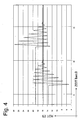
- FIGS. 3 and 4 The convergence in the direction of the sought operating position resulting from carrying out the procedure described above is illustrated in FIGS. 3 and 4 by experimental measurements.
- a system in which, for example, theoretically an actuation position should lie at 16 °, as indicated by the teach-in procedure, is actually located at 15.8 ° can be seen in FIG.
- the initial position of the actuating element was predetermined with a greater deviation from the operating position which was sought after. So it was once started at about 13.5 °, in the second attempt at about 19 °. Again, there was a clear convergence towards the actual existing angle of about 15.8 ° for the sought operating position.
- the force equilibrium between the provided actuating force and a restoring force was specified as a criterion for the reversal of the drive, ie as a criterion for generating an actuating force acting in the opposite direction.
- the equilibrium of forces ie in principle a stoppage of movement, is assumed as a reversal criterion, but the achievement of a specific deflection, starting, for example, from the initial starting position present, or a certain total movement with respect to the last reversal of motion in the other direction.
- the actuation force will initially be so great that it is sufficient to fulfill this criterion or to achieve and thus obtain a reversal. With decreasing the operating force However, this is no longer sufficient to completely pass through or reach the predetermined amplitude of movement or the predetermined range of motion, so that even before reaching, for example, a certain deflection, the criterion of balance of forces and thus a movement arrest occurs. From this phase, this is then also used as a reversal criterion, since the amplitude and the given range of motion which were previously specified and present as a reversal criterion are then no longer attainable or exploitable.
- the further procedure can then be run through to finding the desired position with the balance of power or the movement stop as Um Kunststoffkriterium.
- Um Kunststoffkriterium it is also possible to provide a gradation in the deflection or in the range of motion in the initial phase, so that a certain degree of convergence can already be enforced by initially limiting or reducing the range of motion or the amplitude already here initially acting as a reversal criterion ,
- a convergence takes place, namely a convergence in the area in which ultimately the desired operating position, so for example, the neutral position, associated biasing arrangement is effective, so that then also conditional on the above-described power relationships, a state will set in which the actuating element occupies a position which corresponds to the desired operating end position or is still movable in a range of motion play which covers this actuating position.
- this detected position or the game area are then evaluated in a plausibility check, namely whether compliance with certain requirements exists, so for example, guidelines regarding the theoretical position of the position to be determined. If there is too great a deviation here, that is, a deviation that is too far away from the desired operating position, even taking into account the generally acceptable manufacturing and assembly tolerances, then the procedure can be repeated, for example, possibly occurring during the execution of the procedure Eliminate errors or it may be concluded that in the transmission or the actuation system of the transmission problems exist that do not allow the exact finding a sought operating position. Then, for example, a closer examination can then be made in order to prevent a possibly defective transmission system from being integrated into a vehicle or from a vehicle equipped with it being delivered.
Landscapes
- Engineering & Computer Science (AREA)
- General Engineering & Computer Science (AREA)
- Mechanical Engineering (AREA)
- Gear-Shifting Mechanisms (AREA)
- Control Of Transmission Device (AREA)
- Hydraulic Clutches, Magnetic Clutches, Fluid Clutches, And Fluid Joints (AREA)
Claims (13)
- Procédé pour déterminer une position de commande sur un système de commande de mécanisme, lequel système de commande de mécanisme comprend un élément de commande pouvant être amené par un dispositif actionneur dans une pluralité de positions de commande (P, R, N, D), un dispositif de précontrainte (14) étant attribué à l'élément de commande (10) pour au moins l'une des positions de commande (P, R, N, D), lequel dispositif précontraint l'élément de commande (10) en direction de la position de commande (P, R, N, D) dans le cas où l'élément de commande (10) présente une position située dans une zone de précontrainte autour de la position de commande (P, R, N, D), lequel procédé présente les mesures suivantes :a) déplacement de l'élément de positionnement (10) dans une position initiale dans ou à proximité de la zone de précontrainte,b) sollicitation alternative de l'élément de commande (10) dans des directions opposées avec des forces de commande respectives pour le va-et-vient de l'élément de commande (10) dans la zone de précontrainte,c) pendant l'application de la mesure b) réduction des forces de commande et/ou d'une déviation de l'élément de commande (10),d) dans le cas où l'élément de commande (10) ne se déplace plus d'un côté et de l'autre avec la sollicitation de force présente, détermination de la position occupée dans cet état de l'élément de commande (10) en tant que position de commande, ou lorsque le mouvement de va-et-vient de l'élément de commande (10) est limité à une zone de déplacement prédéfinie, détermination d'une position de l'élément de commande (10) dans la zone de déplacement en tant que position de commande,caractérisé en ce que
un dispositif d'enregistrement de position (12) est attribué à l'élément de commande (10) pour l'enregistrement de la position de l'élément de commande (10) sous la forme d'une valeur réelle d'angle. - Procédé selon la revendication 1,
caractérisé en ce que, au début de la mesure b), l'élément de commande (10) est sollicité de telle sorte qu'il ne peut pas être déplacé à partir de la zone de précontrainte. - Procédé selon la revendication 1 ou 2,
caractérisé en ce que, pendant une période du mouvement de va-et-vient de l'élément de commande (10), les forces de commande agissant sur cet élément dans des directions opposées sont sensiblement identiques. - Procédé selon l'une quelconque des revendications 1 à 3,
caractérisé en ce que la mesure c) comprend la réduction des forces de commande agissant sur l'élément de commande (10) et/ou de la déviation à chaque fois après une période du mouvement de va-et-vient de l'élément de commande (10). - Procédé selon l'une quelconque des revendications 1 à 4,
caractérisé en ce que la mesure c) comprend la réduction des forces de commande agissant sur l'élément de commande (10) et/ou de la déviation dans des étapes prédéfinies. - Procédé selon la revendication 5,
caractérisé en ce que la grandeur d'incrément est modifiable. - Procédé selon l'une quelconque des revendications 1 à 6,
caractérisé en ce que, lors de la mesure b), après la sollicitation de l'élément de commande (10) avec une force de commande dans l'une des directions opposées, cet élément est sollicité alors avec une force de commande dans l'autre des directions opposées lorsque, en cas de sollicitation dans l'une des directions opposées, pratiquement aucun autre déplacement de l'élément de commande (10) n'est généré. - Procédé selon l'une quelconque des revendications 1 à 7,
caractérisé en ce que, lors de la mesure b), après la sollicitation de l'élément de commande (10) avec une force de commande dans l'une des directions opposées, cet élément est sollicité alors avec une force de commande dans l'autre des directions opposées lorsque, en cas de sollicitation dans l'une des directions opposées, une zone de déplacement prédéfinie est traversée et/ou une amplitude de déviation prédéfinie est atteinte. - Procédé selon la revendication 7 et la revendication 8,
caractérisé en ce que, lors de la mesure b), on utilise le critère d'arrêt de mouvement avec sollicitation de force et obtention d'une déviation prédéfinie ou traversée d'une zone de déplacement prédéfinie pour la sollicitation avec une force de commande agissant dans la direction opposée, lequel critère est satisfait en premier. - Procédé selon l'une quelconque des revendications 1 à 9,
caractérisé en ce que, lors de la mesure a), l'élément de commande (10) est amené dans une position qui correspond à une position admise de la position de commande. - Procédé selon l'une quelconque des revendications 1 à 10,
caractérisé en ce que le dispositif de précontrainte (14) comprend un dispositif d'encliquetage (18, 20). - Procédé selon l'une quelconque des revendications 1 à 11,
caractérisé en ce que les mesures a) - d) sont appliquées les unes après les autres pour déterminer plusieurs positions de commande (P, R, N, D). - Procédé pour déterminer une position de commande sur un système de commande de mécanisme, lequel système de commande de mécanisme comprend un élément de commande (10) pouvant être amené par un dispositif actionneur dans une pluralité de positions de commande (P, R, N, D), un dispositif de précontrainte (14) étant attribué à l'élément de commande (10) pour au moins l'une des positions de commande (P, R, N, D), lequel dispositif précontraint l'élément de commande (10) en direction de la position de commande dans le cas où l'élément de commande (10) présente une position disposée dans une zone de précontrainte autour de la position de commande (P, R, N, D), lequel procédé présente les mesures suivantes :a1) sollicitation alternative de l'élément de commande (10) dans des directions opposées avec des forces de commande respectives pour le va-et-vient de l'élément de commande (10) entre deux positions finales de déplacement,b1) pendant l'application de la mesure a1) réduction des forces de commande et/ou d'une déviation de l'élément de positionnement de sorte que la distance aux positions finales de déplacement augmente en cas d'inversion de mouvement,c1) dans les cas où l'élément de commande (10) ne se déplace plus d'un côté ou de l'autre avec la sollicitation de force présente, détermination de la position occupée dans cet état de l'élément de commande (10) en tant que position de commande, ou lorsque le mouvement de va-et-vient de l'élément de commande (10) est limité à une zone de déplacement prédéfinie, détermination d'une position de l'élément de commande (10) dans la zone de déplacement en tant que position de commande,caractérisé en ce que
un dispositif d'enregistrement de position (12) est attribué à l'élément de commande (10) pour l'enregistrement de la position de l'élément de commande (10) sous la forme d'une valeur réelle d'angle.
Applications Claiming Priority (2)
| Application Number | Priority Date | Filing Date | Title |
|---|---|---|---|
| DE102004007082 | 2004-02-13 | ||
| DE102004007082A DE102004007082A1 (de) | 2004-02-13 | 2004-02-13 | Verfahren zum Ermitteln einer Betätigungsstellung bei einem Getriebbetätigungssystem |
Publications (2)
| Publication Number | Publication Date |
|---|---|
| EP1564448A1 EP1564448A1 (fr) | 2005-08-17 |
| EP1564448B1 true EP1564448B1 (fr) | 2006-12-13 |
Family
ID=34684035
Family Applications (1)
| Application Number | Title | Priority Date | Filing Date |
|---|---|---|---|
| EP05001868A Expired - Lifetime EP1564448B1 (fr) | 2004-02-13 | 2005-01-29 | Méthode de détermination de la position d'un système d'actionnement d'une transmission |
Country Status (3)
| Country | Link |
|---|---|
| EP (1) | EP1564448B1 (fr) |
| AT (1) | ATE348279T1 (fr) |
| DE (2) | DE102004007082A1 (fr) |
Families Citing this family (1)
| Publication number | Priority date | Publication date | Assignee | Title |
|---|---|---|---|---|
| DE502007006382D1 (de) | 2007-10-23 | 2011-03-10 | Getrag Ford Transmissions Gmbh | Verfahren zum Erreichen einer Neutralstellung einer Schaltgabel in einem Schaltgetriebe |
Family Cites Families (6)
| Publication number | Priority date | Publication date | Assignee | Title |
|---|---|---|---|---|
| JPS58180327A (ja) * | 1982-04-17 | 1983-10-21 | Diesel Kiki Co Ltd | 自動変速機用位置制御装置 |
| JPH0672659B2 (ja) * | 1985-08-29 | 1994-09-14 | いすゞ自動車株式会社 | 車両用自動変速機のシフト制御装置 |
| AU6147800A (en) * | 1999-06-08 | 2000-12-28 | Luk Lamellen Und Kupplungsbau Beteiligungs Kg | Method for operating an actuation device of an automated transmission |
| DE19957750A1 (de) * | 1999-12-01 | 2001-06-07 | Wabco Gmbh & Co Ohg | Getriebesteuerung |
| DE10045730B4 (de) * | 2000-09-15 | 2007-08-02 | Zf Sachs Ag | Verfahren zum Einlernen wenigstens einer Referenz-Betätigungsstellung einer Stelleinrichtung |
| DE10148666A1 (de) * | 2001-10-02 | 2003-04-10 | Bosch Gmbh Robert | Verfahren zum Auffinden einer Neutralstellung einer automatisierten Schaltung |
-
2004
- 2004-02-13 DE DE102004007082A patent/DE102004007082A1/de not_active Withdrawn
-
2005
- 2005-01-29 AT AT05001868T patent/ATE348279T1/de not_active IP Right Cessation
- 2005-01-29 DE DE502005000222T patent/DE502005000222D1/de not_active Expired - Lifetime
- 2005-01-29 EP EP05001868A patent/EP1564448B1/fr not_active Expired - Lifetime
Also Published As
| Publication number | Publication date |
|---|---|
| DE502005000222D1 (de) | 2007-01-25 |
| ATE348279T1 (de) | 2007-01-15 |
| DE102004007082A1 (de) | 2005-08-25 |
| EP1564448A1 (fr) | 2005-08-17 |
Similar Documents
| Publication | Publication Date | Title |
|---|---|---|
| DE69809245T2 (de) | Automatisches toroidgetriebe für kraftfahrzeuge | |
| DE69011455T2 (de) | Getriebe-Steuervorrichtung mit Detektion fehlerhaften Gangwechsels. | |
| DE3885844T2 (de) | Getriebesteuerungsgerät. | |
| DE19823050B4 (de) | Verfahren und Vorrichtung zur Steuerung einer Kupplung und/oder eines Getriebes | |
| WO2015144148A1 (fr) | Procédé de détermination d'un mode de fonctionnement d'un actionneur à un seul moteur pour boîte de vitesses | |
| EP0795701A2 (fr) | Dispositif de commande d'une boîte de vitesses | |
| EP2992249B1 (fr) | Actionneur de boîte de vitesses pour véhicule automobile, et procédé de commande d'un actionneur de boîte de vitesses | |
| DE112018002004T5 (de) | Schaltbereichssteuerungsvorrichtung | |
| DE102019216643B4 (de) | System zum Lernen einer Position für ein elektrisches shift-by-wire-Schaltsystem | |
| DE112019003001T5 (de) | Elektronischer Parksperrenbetätiger mit begrenzter Drehtrennung | |
| EP2715190B1 (fr) | Procédé pour initialiser l'unité d'actionnement d'un dispositif de commande et dispositif de commande pour boîte de vitesses avec commande sous charge | |
| DE3315221A1 (de) | Betaetigungseinrichtung zum schalten von gaengen und gassen eines fahrzeug-getriebes | |
| WO2009112342A1 (fr) | Procédé d'initialisation d'un dispositif d'actionnement d'un dispositif de couplage d'une transmission | |
| EP1564448B1 (fr) | Méthode de détermination de la position d'un système d'actionnement d'une transmission | |
| DE68913463T2 (de) | Automatisches Steuerungssystem für Getriebe. | |
| DE29621794U1 (de) | Verstellvorrichtung insbesondere für ein Schiebe-Hebe-Dach eines Kraftfahrzeugs | |
| EP1763601B1 (fr) | Dispositif d'entrainement pour un metier a tisser | |
| DE60001985T2 (de) | Schaltstangensteuerung für Getriebe | |
| DE19857714A1 (de) | Getriebe | |
| EP1770313B1 (fr) | Procédé et dispositf destinés à l'utilisation d'un dispositif d'entraînement | |
| WO2015149798A1 (fr) | Système d'actionnement de commutateur à cames dans une réalisation augmentant la dynamique par une élévation de la tension | |
| DE10224062C1 (de) | Verfahren zum Betrieb eines automatisierten Zahnräderwechselgetriebes | |
| DE10225467A1 (de) | Vorrichtung zur Durchführung von Schaltvorgängen von Getrieben eines Kraftfahrzeuges | |
| DE10217908A1 (de) | Stelleinrichtung | |
| DE102006002492A1 (de) | Kraftfahrzeug-Getriebeaktor für die Betätigung eines Kraftfahrzeug Getriebes, Kraftfahrzeug-Getriebeeinrichtung sowie Verfahren zur Bestimmung einer Referenzposition eines Kraftfahrzeug-Getriebeaktors für eine Inkrementalgeber-Einrichtung |
Legal Events
| Date | Code | Title | Description |
|---|---|---|---|
| PUAI | Public reference made under article 153(3) epc to a published international application that has entered the european phase |
Free format text: ORIGINAL CODE: 0009012 |
|
| AK | Designated contracting states |
Kind code of ref document: A1 Designated state(s): AT BE BG CH CY CZ DE DK EE ES FI FR GB GR HU IE IS IT LI LT LU MC NL PL PT RO SE SI SK TR |
|
| AX | Request for extension of the european patent |
Extension state: AL BA HR LV MK YU |
|
| 17P | Request for examination filed |
Effective date: 20050625 |
|
| AKX | Designation fees paid |
Designated state(s): AT BE BG CH CY CZ DE DK EE ES FI FR GB GR HU IE IS IT LI LT LU MC NL PL PT RO SE SI SK TR |
|
| GRAP | Despatch of communication of intention to grant a patent |
Free format text: ORIGINAL CODE: EPIDOSNIGR1 |
|
| GRAS | Grant fee paid |
Free format text: ORIGINAL CODE: EPIDOSNIGR3 |
|
| GRAA | (expected) grant |
Free format text: ORIGINAL CODE: 0009210 |
|
| AK | Designated contracting states |
Kind code of ref document: B1 Designated state(s): AT BE BG CH CY CZ DE DK EE ES FI FR GB GR HU IE IS IT LI LT LU MC NL PL PT RO SE SI SK TR |
|
| PG25 | Lapsed in a contracting state [announced via postgrant information from national office to epo] |
Ref country code: CZ Free format text: LAPSE BECAUSE OF FAILURE TO SUBMIT A TRANSLATION OF THE DESCRIPTION OR TO PAY THE FEE WITHIN THE PRESCRIBED TIME-LIMIT Effective date: 20061213 Ref country code: PL Free format text: LAPSE BECAUSE OF FAILURE TO SUBMIT A TRANSLATION OF THE DESCRIPTION OR TO PAY THE FEE WITHIN THE PRESCRIBED TIME-LIMIT Effective date: 20061213 Ref country code: IT Free format text: LAPSE BECAUSE OF FAILURE TO SUBMIT A TRANSLATION OF THE DESCRIPTION OR TO PAY THE FEE WITHIN THE PRESCRIBED TIME-LIMIT;WARNING: LAPSES OF ITALIAN PATENTS WITH EFFECTIVE DATE BEFORE 2007 MAY HAVE OCCURRED AT ANY TIME BEFORE 2007. THE CORRECT EFFECTIVE DATE MAY BE DIFFERENT FROM THE ONE RECORDED. Effective date: 20061213 Ref country code: NL Free format text: LAPSE BECAUSE OF FAILURE TO SUBMIT A TRANSLATION OF THE DESCRIPTION OR TO PAY THE FEE WITHIN THE PRESCRIBED TIME-LIMIT Effective date: 20061213 Ref country code: RO Free format text: LAPSE BECAUSE OF FAILURE TO SUBMIT A TRANSLATION OF THE DESCRIPTION OR TO PAY THE FEE WITHIN THE PRESCRIBED TIME-LIMIT Effective date: 20061213 Ref country code: SI Free format text: LAPSE BECAUSE OF FAILURE TO SUBMIT A TRANSLATION OF THE DESCRIPTION OR TO PAY THE FEE WITHIN THE PRESCRIBED TIME-LIMIT Effective date: 20061213 Ref country code: SK Free format text: LAPSE BECAUSE OF FAILURE TO SUBMIT A TRANSLATION OF THE DESCRIPTION OR TO PAY THE FEE WITHIN THE PRESCRIBED TIME-LIMIT Effective date: 20061213 Ref country code: DK Free format text: LAPSE BECAUSE OF FAILURE TO SUBMIT A TRANSLATION OF THE DESCRIPTION OR TO PAY THE FEE WITHIN THE PRESCRIBED TIME-LIMIT Effective date: 20061213 Ref country code: FI Free format text: LAPSE BECAUSE OF FAILURE TO SUBMIT A TRANSLATION OF THE DESCRIPTION OR TO PAY THE FEE WITHIN THE PRESCRIBED TIME-LIMIT Effective date: 20061213 Ref country code: LT Free format text: LAPSE BECAUSE OF FAILURE TO SUBMIT A TRANSLATION OF THE DESCRIPTION OR TO PAY THE FEE WITHIN THE PRESCRIBED TIME-LIMIT Effective date: 20061213 Ref country code: IE Free format text: LAPSE BECAUSE OF FAILURE TO SUBMIT A TRANSLATION OF THE DESCRIPTION OR TO PAY THE FEE WITHIN THE PRESCRIBED TIME-LIMIT Effective date: 20061213 |
|
| REG | Reference to a national code |
Ref country code: GB Ref legal event code: FG4D Free format text: NOT ENGLISH |
|
| REG | Reference to a national code |
Ref country code: CH Ref legal event code: EP |
|
| REG | Reference to a national code |
Ref country code: IE Ref legal event code: FG4D Free format text: LANGUAGE OF EP DOCUMENT: GERMAN |
|
| REF | Corresponds to: |
Ref document number: 502005000222 Country of ref document: DE Date of ref document: 20070125 Kind code of ref document: P |
|
| PG25 | Lapsed in a contracting state [announced via postgrant information from national office to epo] |
Ref country code: MC Free format text: LAPSE BECAUSE OF NON-PAYMENT OF DUE FEES Effective date: 20070131 |
|
| PG25 | Lapsed in a contracting state [announced via postgrant information from national office to epo] |
Ref country code: BG Free format text: LAPSE BECAUSE OF FAILURE TO SUBMIT A TRANSLATION OF THE DESCRIPTION OR TO PAY THE FEE WITHIN THE PRESCRIBED TIME-LIMIT Effective date: 20070313 Ref country code: SE Free format text: LAPSE BECAUSE OF FAILURE TO SUBMIT A TRANSLATION OF THE DESCRIPTION OR TO PAY THE FEE WITHIN THE PRESCRIBED TIME-LIMIT Effective date: 20070313 |
|
| PG25 | Lapsed in a contracting state [announced via postgrant information from national office to epo] |
Ref country code: ES Free format text: LAPSE BECAUSE OF FAILURE TO SUBMIT A TRANSLATION OF THE DESCRIPTION OR TO PAY THE FEE WITHIN THE PRESCRIBED TIME-LIMIT Effective date: 20070324 |
|
| GBT | Gb: translation of ep patent filed (gb section 77(6)(a)/1977) |
Effective date: 20070314 |
|
| PG25 | Lapsed in a contracting state [announced via postgrant information from national office to epo] |
Ref country code: IS Free format text: LAPSE BECAUSE OF FAILURE TO SUBMIT A TRANSLATION OF THE DESCRIPTION OR TO PAY THE FEE WITHIN THE PRESCRIBED TIME-LIMIT Effective date: 20070413 |
|
| PG25 | Lapsed in a contracting state [announced via postgrant information from national office to epo] |
Ref country code: PT Free format text: LAPSE BECAUSE OF FAILURE TO SUBMIT A TRANSLATION OF THE DESCRIPTION OR TO PAY THE FEE WITHIN THE PRESCRIBED TIME-LIMIT Effective date: 20070514 |
|
| ET | Fr: translation filed | ||
| NLV1 | Nl: lapsed or annulled due to failure to fulfill the requirements of art. 29p and 29m of the patents act | ||
| REG | Reference to a national code |
Ref country code: IE Ref legal event code: FD4D |
|
| PLBE | No opposition filed within time limit |
Free format text: ORIGINAL CODE: 0009261 |
|
| STAA | Information on the status of an ep patent application or granted ep patent |
Free format text: STATUS: NO OPPOSITION FILED WITHIN TIME LIMIT |
|
| 26N | No opposition filed |
Effective date: 20070914 |
|
| BERE | Be: lapsed |
Owner name: ZF FRIEDRICHSHAFEN A.G. Effective date: 20070131 |
|
| PG25 | Lapsed in a contracting state [announced via postgrant information from national office to epo] |
Ref country code: BE Free format text: LAPSE BECAUSE OF NON-PAYMENT OF DUE FEES Effective date: 20070131 |
|
| PG25 | Lapsed in a contracting state [announced via postgrant information from national office to epo] |
Ref country code: GR Free format text: LAPSE BECAUSE OF FAILURE TO SUBMIT A TRANSLATION OF THE DESCRIPTION OR TO PAY THE FEE WITHIN THE PRESCRIBED TIME-LIMIT Effective date: 20070314 |
|
| PG25 | Lapsed in a contracting state [announced via postgrant information from national office to epo] |
Ref country code: AT Free format text: LAPSE BECAUSE OF NON-PAYMENT OF DUE FEES Effective date: 20070129 |
|
| PG25 | Lapsed in a contracting state [announced via postgrant information from national office to epo] |
Ref country code: EE Free format text: LAPSE BECAUSE OF FAILURE TO SUBMIT A TRANSLATION OF THE DESCRIPTION OR TO PAY THE FEE WITHIN THE PRESCRIBED TIME-LIMIT Effective date: 20061213 |
|
| PG25 | Lapsed in a contracting state [announced via postgrant information from national office to epo] |
Ref country code: LU Free format text: LAPSE BECAUSE OF NON-PAYMENT OF DUE FEES Effective date: 20070129 Ref country code: CY Free format text: LAPSE BECAUSE OF FAILURE TO SUBMIT A TRANSLATION OF THE DESCRIPTION OR TO PAY THE FEE WITHIN THE PRESCRIBED TIME-LIMIT Effective date: 20061213 |
|
| REG | Reference to a national code |
Ref country code: CH Ref legal event code: PL |
|
| PG25 | Lapsed in a contracting state [announced via postgrant information from national office to epo] |
Ref country code: TR Free format text: LAPSE BECAUSE OF FAILURE TO SUBMIT A TRANSLATION OF THE DESCRIPTION OR TO PAY THE FEE WITHIN THE PRESCRIBED TIME-LIMIT Effective date: 20061213 Ref country code: HU Free format text: LAPSE BECAUSE OF FAILURE TO SUBMIT A TRANSLATION OF THE DESCRIPTION OR TO PAY THE FEE WITHIN THE PRESCRIBED TIME-LIMIT Effective date: 20070614 |
|
| PG25 | Lapsed in a contracting state [announced via postgrant information from national office to epo] |
Ref country code: LI Free format text: LAPSE BECAUSE OF NON-PAYMENT OF DUE FEES Effective date: 20090131 Ref country code: CH Free format text: LAPSE BECAUSE OF NON-PAYMENT OF DUE FEES Effective date: 20090131 |
|
| PGFP | Annual fee paid to national office [announced via postgrant information from national office to epo] |
Ref country code: FR Payment date: 20100208 Year of fee payment: 6 |
|
| PGFP | Annual fee paid to national office [announced via postgrant information from national office to epo] |
Ref country code: DE Payment date: 20100121 Year of fee payment: 6 Ref country code: GB Payment date: 20100202 Year of fee payment: 6 |
|
| GBPC | Gb: european patent ceased through non-payment of renewal fee |
Effective date: 20110129 |
|
| REG | Reference to a national code |
Ref country code: FR Ref legal event code: ST Effective date: 20110930 |
|
| PG25 | Lapsed in a contracting state [announced via postgrant information from national office to epo] |
Ref country code: FR Free format text: LAPSE BECAUSE OF NON-PAYMENT OF DUE FEES Effective date: 20110131 |
|
| PG25 | Lapsed in a contracting state [announced via postgrant information from national office to epo] |
Ref country code: GB Free format text: LAPSE BECAUSE OF NON-PAYMENT OF DUE FEES Effective date: 20110129 |
|
| REG | Reference to a national code |
Ref country code: DE Ref legal event code: R119 Ref document number: 502005000222 Country of ref document: DE Effective date: 20110802 |
|
| PG25 | Lapsed in a contracting state [announced via postgrant information from national office to epo] |
Ref country code: DE Free format text: LAPSE BECAUSE OF NON-PAYMENT OF DUE FEES Effective date: 20110802 |