EP1563958A1 - Procédé et dispositif de préhension et maintien d'un panneau mince, flexible, avec une pluralité de ventouses - Google Patents
Procédé et dispositif de préhension et maintien d'un panneau mince, flexible, avec une pluralité de ventouses Download PDFInfo
- Publication number
- EP1563958A1 EP1563958A1 EP20050100865 EP05100865A EP1563958A1 EP 1563958 A1 EP1563958 A1 EP 1563958A1 EP 20050100865 EP20050100865 EP 20050100865 EP 05100865 A EP05100865 A EP 05100865A EP 1563958 A1 EP1563958 A1 EP 1563958A1
- Authority
- EP
- European Patent Office
- Prior art keywords
- panel
- suction
- suction cup
- face
- suction cups
- Prior art date
- Legal status (The legal status is an assumption and is not a legal conclusion. Google has not performed a legal analysis and makes no representation as to the accuracy of the status listed.)
- Granted
Links
Images


Classifications
-
- B—PERFORMING OPERATIONS; TRANSPORTING
- B23—MACHINE TOOLS; METAL-WORKING NOT OTHERWISE PROVIDED FOR
- B23Q—DETAILS, COMPONENTS, OR ACCESSORIES FOR MACHINE TOOLS, e.g. ARRANGEMENTS FOR COPYING OR CONTROLLING; MACHINE TOOLS IN GENERAL CHARACTERISED BY THE CONSTRUCTION OF PARTICULAR DETAILS OR COMPONENTS; COMBINATIONS OR ASSOCIATIONS OF METAL-WORKING MACHINES, NOT DIRECTED TO A PARTICULAR RESULT
- B23Q1/00—Members which are comprised in the general build-up of a form of machine, particularly relatively large fixed members
- B23Q1/03—Stationary work or tool supports
- B23Q1/035—Stationary work or tool supports with an array of longitudinally movable rods defining a reconfigurable support surface
-
- B—PERFORMING OPERATIONS; TRANSPORTING
- B23—MACHINE TOOLS; METAL-WORKING NOT OTHERWISE PROVIDED FOR
- B23Q—DETAILS, COMPONENTS, OR ACCESSORIES FOR MACHINE TOOLS, e.g. ARRANGEMENTS FOR COPYING OR CONTROLLING; MACHINE TOOLS IN GENERAL CHARACTERISED BY THE CONSTRUCTION OF PARTICULAR DETAILS OR COMPONENTS; COMBINATIONS OR ASSOCIATIONS OF METAL-WORKING MACHINES, NOT DIRECTED TO A PARTICULAR RESULT
- B23Q3/00—Devices holding, supporting, or positioning work or tools, of a kind normally removable from the machine
- B23Q3/02—Devices holding, supporting, or positioning work or tools, of a kind normally removable from the machine for mounting on a work-table, tool-slide, or analogous part
- B23Q3/06—Work-clamping means
- B23Q3/062—Work-clamping means adapted for holding workpieces having a special form or being made from a special material
- B23Q3/065—Work-clamping means adapted for holding workpieces having a special form or being made from a special material for holding workpieces being specially deformable, e.g. made from thin-walled or elastic material
-
- B—PERFORMING OPERATIONS; TRANSPORTING
- B25—HAND TOOLS; PORTABLE POWER-DRIVEN TOOLS; MANIPULATORS
- B25B—TOOLS OR BENCH DEVICES NOT OTHERWISE PROVIDED FOR, FOR FASTENING, CONNECTING, DISENGAGING, OR HOLDING
- B25B11/00—Work holders not covered by any preceding group in the subclass, e.g. magnetic work holders, vacuum work holders
- B25B11/005—Vacuum work holders
-
- B—PERFORMING OPERATIONS; TRANSPORTING
- B25—HAND TOOLS; PORTABLE POWER-DRIVEN TOOLS; MANIPULATORS
- B25B—TOOLS OR BENCH DEVICES NOT OTHERWISE PROVIDED FOR, FOR FASTENING, CONNECTING, DISENGAGING, OR HOLDING
- B25B11/00—Work holders not covered by any preceding group in the subclass, e.g. magnetic work holders, vacuum work holders
- B25B11/005—Vacuum work holders
- B25B11/007—Vacuum work holders portable, e.g. handheld
Definitions
- the present invention relates to a method of gripping and holding located in the isostatic position of a thin, flexible panel, particularly complex form that can be non-developable.
- the invention applies to any panel-shaped part in particular metal, with a thin wall and any dimensions that can be important, such as aircraft fuselage liner panels.
- the position is measured by report to said support of each sucker in order to calculate the actual shape of the part of the face of the panel opposite said suckers.
- the subject of the invention is also a device for implementing the process above, characterized in that it comprises a support plate carrying three positioning stops arranged in a triangle and a plurality of devices with a suction cup regularly distributed in the space between said stops, each device comprising a suction cup slidably mounted perpendicular to the platinum, and means adapted to apply the suction cup against the face of the panel, the vacuum, then lock it in its gripping position without deformation local of said panel.
- each device to Suction cup is associated with a sensor measuring the position of the suction cup by relative to said support plate.
- the assembly forms a device for holding the panel part in look at platinum under isostatic conditions that can serve as a reference useful for various interventions requiring stable positioning without constraints at least in the area of application of the suction cups as well that eventually the precise knowledge of the actual shape of the face of the panel facing the suction cups.
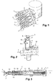
- FIG. 1 shows a gripping and holding device located of a panel according to the invention.
- the device comprises a support plate 1, for example square, of 500 mm side, on the side facing the panel to be seized of which are arranged projecting, on the one hand, three fixed stops 2 arranged in a triangle and, on the other hand, a number of suction devices 2 regularly distributed, all elements 2,3 covering the entire surface of the plate 1.
- the stops 2 are rectilinear pins with spherical ends arranged perpendicular to the plate 1 and the same length.
- the stops 2 are preferably the farthest possible between them and are, as illustrated by the figure, arranged, two in two angles of the plate 1 and the third in the middle of the opposite side of the stage.
- the suction devices 3 are preferably regularly distributed and aligned on the entire remaining surface of the plate, parallel to the stops 2, with a step between devices 3 constant, less than 150 mm.
- Each device 3 comprises ( Figures 1 to 3) a sleeve 4 mounted mobile axially on the plate 1 and in which slides a centralizer 5 provided with its end of a suction cup.
- the sheath 4 is moved by a training-and-locking device comprising a motor 7 driving a ball screw 8 stopped in the plate 1, by through a bearing, a nut 9 engaged with the screw 8 and a device fastening 10 secured to the nut 9 whose jaws 11, when spaced apart, plaque against the inner wall of the sleeve 4 making it integral with the nut 9.
- a training-and-locking device comprising a motor 7 driving a ball screw 8 stopped in the plate 1, by through a bearing, a nut 9 engaged with the screw 8 and a device fastening 10 secured to the nut 9 whose jaws 11, when spaced apart, plaque against the inner wall of the sleeve 4 making it integral with the nut 9.
- the sheath 4 carries at its end the centering device (5) and suction device (6) comprising (FIGS. 4a, 4b) a sleeve 12 connected to the sleeve 4 by by means of a pivoted connection 13 and closed by a movable cover 14 by relative to the sheath 12, axially to the latter under the action of an element tire called muscle 15, capable of contraction (FIG. 4b) or elongation (relaxation, figure 4a).
- a sleeve 12 connected to the sleeve 4 by by means of a pivoted connection 13 and closed by a movable cover 14 by relative to the sheath 12, axially to the latter under the action of an element tire called muscle 15, capable of contraction (FIG. 4b) or elongation (relaxation, figure 4a).
- FIG. 2 there is shown a locking device for the sheath 4 relative to the plate 1.
- the device 16 is fixed on the plate and squeezes by two arm 17 the sheath 4.
- In 18 is represented a sensor for measuring the distance separating it from the face of the panel opposite, that is to say the distance of the suction cup 6 opposite platinum 1.
- the sensor 18 is fixed by a lug 19 laterally to the sheath 4.
- the panel to be maintained for example the panel p (FIG. 5), is all first brought into contact by its convex face 1a, for example, against the three stops 2 of the device of FIG. 1, without deformation of the panel, by any appropriate means, for example through several Pusher arms symbolized in P in Figure 5, applied against the concave face 1b towards the support plate 1 of the device.
- Suction devices 3 is performed by operating the motor 7 of the devices 3.
- the rotation of the screw 8 drives, the jaws 11 of the device 10 being expanded and the arms 17 of the device 16 being loosened, the displacement in translation of the sleeve 4-centralizer assembly 5 in direction of the face 1a of the panel p.
- step 21, FIG. 4c is the depression of the cupping 6 together.
- the panel p thus "sucked” is sticking against the bottom suction cups. These being offset with respect to the theoretical position of the panel p, it is placed locally in constraint.
- the muscles 15 (FIG. 4a) are then released (step 22, FIG. 4c) so that that, by elastic return, the panel p resumes its free form of stress, the lid 14 separating from the sheath 12.
- the suction cup 6 is then glued to the panel and the assembly 6, 14 being maintained by the elasticity (empty) of the pneumatic muscle 15. Because of their own weight, low, and their maintenance by the elasticity of the muscle 15, said elements 6, 14 do not solicit or little p panel (step 23, Figure 4c).
- the next step is to re-rigidify the set 1-3, the panel p having resumed its natural form, without constraint.
- step 24, FIG. 4c we go to release externally the sleeve 4 by loosening the arms 17 and retract the jaws 11 to liberate the sleeve 4.
- step 25, FIG. muscle 15 the assembly 5-4 approaches the panel p and the sheath 12 becomes re-inserted in the cover 14 ( Figure 4b).
- step 26 consists in re-immobilizing the sheath 4 with respect to the plate 1, by the jaws 11 of the device 10 and by the arms 17 of the device 16.
- the panel p is, at the right of the plate 1, perfectly immobilized, of stably, without deformation or strain in this part of the panel and, extra, we can know the actual shape of the face 1a next to the turntable 1 by calculation from the measurements given by the sensors 18 which give the precise position of the face 1a relative to the plate 1 to the right of each Suction device 3. Interpolation calculation from these measurement points allows to know the actual shape of said face 1a.
- the sleeves 4 of the devices 3 are more or less protruding from the face of the plate 1 facing the panel p because of the curvature of the latter.
- the set of suction cups 6 automatically adapts to the shape (convex or concave) of the panel p.
- the device as shown in FIG. 1 can be mounted on a multi-axis manipulator and be integrated for example on a machining machine.
- FIGS. 6A and 6B An example of a suction device is more particularly represented in FIGS. 6A and 6B in the context of a variant of the invention allowing a gripping of the panel in four phases, namely docking, locking in position sheaths suction devices, loosening device by device for to obtain an elastic relaxation of the stress free panel then a reblocking device panel by device to re-stiffen the assembly.
- the suction device comprises according to this example a guide 40 which slides a sleeve 4 carrying the suction cup 6, mounted on a ball 61, FIG. 6A.
- the sheath 4 is actuated by a jack 42 to exit the guide 40 during the docking phase until a touch point 43 comes into contact with the panel, this touch tip coming into contact with a combined sensor 44 to the sensor 18 for moving the suction cup that commands the stop of the movement of the sheath 4.
- a locking device 45 then blocks the sheath in position which secures the sleeve 4 to the guide 40 by opposing the effort applied by the cylinder 42 whose thrust force is chosen less than the force developed by the blocking device.
- a vacuum is then created in the suction cup 6 using the vacuum tube 46 for stick the lips of the sucker on the panel.
- the docking phase takes place simultaneously for all suction cups on the panel and once this phase is completed, the set of cylinders 42 is put in the open air so they do not exert any more effort on the sheaths.
- a measure of the shape of the panel is made once the looseness completed using the sensors 18 for measuring the position of the suction cup.
- the invention applies to all types of panels in the broad sense defined more high, regardless of the constituent material, such as metal or composite material and whatever the manufacturing process.
Landscapes
- Engineering & Computer Science (AREA)
- Mechanical Engineering (AREA)
- Manipulator (AREA)
- Hooks, Suction Cups, And Attachment By Adhesive Means (AREA)
- Automatic Assembly (AREA)
- Sheets, Magazines, And Separation Thereof (AREA)
- Feeding Of Articles By Means Other Than Belts Or Rollers (AREA)
- Length Measuring Devices With Unspecified Measuring Means (AREA)
- Laminated Bodies (AREA)
Abstract
Description
- plaquer l'une des faces du panneau sans déformation, contre un système d'appui à trois points,
- appliquer sur ladite face, dans la zone d'appui, une pluralité de ventouses de saisie, mobiles par rapport à un support de référence, et
- bloquer par rapport audit support chaque ventouse dans sa position de préhension sans déformation locale de la face du panneau.
- la figure 1 est une vue en perspective d'un dispositif de maintien en position selon l'invention ;
- la figure 2 est une vue d'un dispositif à ventouse,
- la figure 3 est une vue en coupe axiale du dispositif de la figure 2 ;
- la figure 4a et 4b illustrent le fonctionnement du dispositif à ventouse ;
- la figure 4c est un organigramme de fonctionnement du dispositif à ventouse, et
- la figure 5 est un schéma illustrant l'application sur une face d'un panneau à double courbure d'un dispositif de l'invention;
- les figures 6A, 6B sont des vues en coupe d'un dispositif à ventouse d'un dispositif de maintien selon l'invention.
Claims (10)
- Procédé de préhension et maintien localisé d'un panneau mince (p), flexible, en particulier de forme complexe, notamment non-développable, caractérisé en ce qu'il comporte les étapes consistant à :plaquer l'une des faces (1a) du panneau (p) sans déformation, contre un système d'appui (2) à trois points,appliquer sur ladite face (1a), dans la zone d'appui, une pluralité de ventouses (6) de saisie, mobiles par rapport à un support de référence (1), etbloquer par rapport audit support (1) chaque ventouse (6) dans sa position de préhension sans déformation locale de la face (1a) du panneau (p).
- Procédé suivant la revendication 1, caractérisé en ce qu'on mesure la position par rapport audit support (1) de chaque ventouse (6) afin de calculer la forme réelle de la partie de la face (1a) du panneau (p) en regard desdites ventouses (6).
- ; Procédé suivant la revendication 1 ou 2, caractérisé en ce qu'il comporte en outre une étape consistant en un relâchement du blocage de la position des ventouses et une étape ultérieure consistant à re-bloquer chaque ventouse dans sa position de préhension sans déformation locale de la face (1a) du panneau.
- Procédé selon la revendication 3, caractérisé en ce que les ventouses étant orientables, il comporte une étape de réorientation des ventouses par application d'une dépression entre la ventouse et le panneau lors dudit relâchement.
- Dispositif pour la mise en oeuvre du procédé selon l'une des revendications 1 à 4, caractérisé en ce qu'il comprend une platine-support (1) portant trois butées (2) de positionnement disposées en triangle et une pluralité de dispositifs à ventouse (3) distribués régulièrement dans l'espace entre lesdites butées (2), chaque dispositif (3) comprenant une ventouse (6) montée coulissante perpendiculairement à la platine (1), et des moyens (7 à 17) aptes à appliquer la ventouse (6) contre la face (1a) du panneau (p), la mettre sous vide, puis la bloquer dans une position de saisie sans déformation locale dudit panneau.
- Dispositif suivant la revendication 5, caractérisé en ce qu'à chaque dispositif à ventouse (3) est associé un capteur (18) de mesure de la position de la ventouse (6) par rapport à ladite platine-support (1).
- Dispositif suivant la revendication 5 ou 6, caractérisé en ce que lesdits moyens de positionnement-blocage de chaque ventouse (6) comportent des moyens (9,10,11), désolidarisables, d'entraínement en translation d'un fourreau (4, 41) et des moyens (16,17, 45), désolidarisables, de blocage du déplacement dudit fourreau (4, 41)
- Dispositif suivant la revendication 7, caractérisé en ce qu'il comporte un centreur (5) monté coulissant dans ledit fourreau (4) et relié à une ventouse (6) par l'intermédiaire d'un muscle (15) contractible.
- Dispositif selon l'une des revendications 7 ou 8, caractérisé en ce que les ventouses (6) sont des ventouses orientables reliées aux fourreaux par l'intermédiaire de rotules (61).
- Dispositif selon l'une des revendications 7 à 9 caractérisé en ce que les ventouses (6) sont associées à des pointes de touche (43) de détection de contact avec le panneau (p).
Applications Claiming Priority (2)
| Application Number | Priority Date | Filing Date | Title |
|---|---|---|---|
| FR0401278 | 2004-02-10 | ||
| FR0401278A FR2865953B1 (fr) | 2004-02-10 | 2004-02-10 | Procede et dispositif de prehension et maintien localise d'un panneau mince, flexible, en particulier de forme complexe |
Publications (2)
| Publication Number | Publication Date |
|---|---|
| EP1563958A1 true EP1563958A1 (fr) | 2005-08-17 |
| EP1563958B1 EP1563958B1 (fr) | 2007-08-15 |
Family
ID=34684999
Family Applications (1)
| Application Number | Title | Priority Date | Filing Date |
|---|---|---|---|
| EP20050100865 Expired - Lifetime EP1563958B1 (fr) | 2004-02-10 | 2005-02-08 | Procédé et dispositif de préhension et maintien d'un panneau mince, flexible, avec une pluralité de ventouses |
Country Status (6)
| Country | Link |
|---|---|
| US (1) | US7416176B2 (fr) |
| EP (1) | EP1563958B1 (fr) |
| AT (1) | ATE369943T1 (fr) |
| CA (1) | CA2496754C (fr) |
| DE (1) | DE602005001950T2 (fr) |
| FR (1) | FR2865953B1 (fr) |
Cited By (7)
| Publication number | Priority date | Publication date | Assignee | Title |
|---|---|---|---|---|
| CN103128567A (zh) * | 2013-02-26 | 2013-06-05 | 哈尔滨汽轮机厂有限责任公司 | 轴向拉紧夹具 |
| WO2014179107A1 (fr) * | 2013-05-02 | 2014-11-06 | The Boeing Company | Système et procédé d'assemblage de composants |
| CN104647090A (zh) * | 2014-12-08 | 2015-05-27 | 南京航空航天大学 | 飞机蒙皮自适应吸附装夹装置 |
| WO2016046474A1 (fr) * | 2014-09-26 | 2016-03-31 | Stelia Aerospace | Dispositif de bridage d'une pièce brute à usiner |
| EP2277777A4 (fr) * | 2008-05-19 | 2017-12-27 | Airbus Operations S.L. | Procédé et outil de montage de caissons de torsion pour une utilisation aéronautique |
| EP3395496A1 (fr) * | 2017-04-07 | 2018-10-31 | Schunk GmbH & Co. KG Spann- und Greiftechnik | Unité de serrage pourvue de module de serrage et système de serrage |
| CN119551208A (zh) * | 2024-11-12 | 2025-03-04 | 四川大学 | 一种飞机柔性工装系统及其控制方法 |
Families Citing this family (36)
| Publication number | Priority date | Publication date | Assignee | Title |
|---|---|---|---|---|
| FR2865954B1 (fr) * | 2004-02-10 | 2006-06-23 | Airbus France | Procede et dispositif d'usinage par fenetrage de panneaux minces non-developpables |
| FR2865953B1 (fr) * | 2004-02-10 | 2006-08-04 | Airbus France | Procede et dispositif de prehension et maintien localise d'un panneau mince, flexible, en particulier de forme complexe |
| JP5073230B2 (ja) * | 2006-06-20 | 2012-11-14 | 東京応化工業株式会社 | 支持ピン |
| US20080164646A1 (en) * | 2007-01-09 | 2008-07-10 | Chi Wah Cheng | Workholder for supporting electronic devices |
| KR100817254B1 (ko) * | 2007-03-27 | 2008-03-27 | 한국뉴매틱(주) | 내장 진공펌프를 갖는 레벨 보정기 |
| EP2093018B2 (fr) * | 2008-02-25 | 2017-11-01 | Satisloh AG | Pièce de bloc pour maintenir une pièce de travail optique, en particulier un verre de lunette, pour traitement associé, et procédé de fabrication de verres de lunettes selon une prescription |
| DE202008010424U1 (de) * | 2008-07-30 | 2009-12-24 | J. Schmalz Gmbh | Mit Druckluft betriebener Flächensauggreifer |
| KR20120036954A (ko) * | 2009-07-17 | 2012-04-18 | 로버트 에이. 사막 | 자동화되고 조절가능한, 공작기계 가공물 장착 장치 |
| CN102549511B (zh) * | 2009-08-06 | 2014-12-17 | 美国派尔(PaR)系统有限公司 | 柔性固定设备 |
| CN102490131B (zh) * | 2011-11-11 | 2014-02-19 | 江苏大学 | 可调式薄壁箱体真空夹具 |
| EP2602099B1 (fr) * | 2011-12-08 | 2014-02-12 | Harro Höfliger Verpackungsmaschinen GmbH | Pince aspirante et système de manipulation pour lentilles de contact |
| US9327376B2 (en) | 2012-10-30 | 2016-05-03 | The Boeing Company | Dual function movement component for automated assembly systems |
| US10065280B2 (en) | 2012-10-30 | 2018-09-04 | The Boeing Company | Multifunction legs for autonomous crawling assembly equipment |
| US9475527B2 (en) | 2012-10-30 | 2016-10-25 | The Boeing Company | Autonomous crawling assembly system |
| CN103878605A (zh) * | 2014-02-28 | 2014-06-25 | 成都飞机工业(集团)有限责任公司 | 飞机蒙皮零件自动钻铆成型定位装置 |
| EP3180159B1 (fr) * | 2014-07-22 | 2021-04-07 | Blue Photon Technology&workholding Systems LLC | Procédé et dispositifs pour minimiser une distorsion de pièce à travailler due à des contraintes d'adhérence et à des changements dans des contraintes internes |
| CN104191271B (zh) * | 2014-09-01 | 2016-08-03 | 宁夏共享精密加工有限公司 | 一种大型薄壁磨机端盖防变形支顶装置及方法 |
| DE202014007224U1 (de) * | 2014-09-11 | 2015-12-14 | Sauer Gmbh | Werkzeugmaschine |
| CN104589118B (zh) * | 2014-11-24 | 2017-08-25 | 上海拓璞数控科技股份有限公司 | 薄壁件镜像加工的多点阻尼支撑装置 |
| US10655658B2 (en) * | 2016-01-20 | 2020-05-19 | Persimmon Technologies, Corp. | Material handling system |
| KR101897023B1 (ko) * | 2016-10-05 | 2018-09-12 | 한국생산기술연구원 | 가공지지부를 갖는 복합가공장비 |
| CN107627127A (zh) * | 2017-11-17 | 2018-01-26 | 哈尔滨哈飞工业有限责任公司 | 一种薄壁件加工防变形装置 |
| CN109968156A (zh) * | 2017-12-27 | 2019-07-05 | 中国科学院宁波材料技术与工程研究所 | 一种纤维制品自动化综合工作台及其运行方法 |
| US10814459B2 (en) * | 2018-02-09 | 2020-10-27 | The Boeing Company | Apparatus and method for holding a workpiece |
| CN109031710B (zh) * | 2018-03-27 | 2023-11-10 | 中山市正科电器实业有限公司 | 一种液晶显示器的检查装置 |
| CN110920927A (zh) * | 2019-11-06 | 2020-03-27 | 浙江大学 | 一种柔性壁板装配工装 |
| CN110715851A (zh) * | 2019-12-10 | 2020-01-21 | 安徽鼎元新材料有限公司 | 一种pir聚异氰尿酸脂制品的抗压强度检测装置 |
| US12343828B2 (en) * | 2020-11-25 | 2025-07-01 | Tpi Composites, Inc. | Universal supporting member for wind turbine blade |
| WO2022238316A1 (fr) * | 2021-05-10 | 2022-11-17 | IMI Norgren Herion Pvt. Ltd. | Appareil de fixation et de serrage adaptatif et modulaire |
| EP4359177A4 (fr) * | 2021-06-09 | 2025-10-08 | Plus One Robotics Inc | Système de préhension par aspiration ayant un bras de préhension extensible |
| CN113816144A (zh) * | 2021-08-23 | 2021-12-21 | 甘肃旭盛显示科技有限公司 | 玻璃基板取板装置及玻璃基板生产线 |
| CN114559275B (zh) * | 2022-03-17 | 2023-03-14 | 南京航空航天大学 | 弱刚度薄壁件加工用位姿调节支撑装置 |
| CN115070451B (zh) * | 2022-07-22 | 2023-06-13 | 大连理工大学 | 一种壁板整体形变可控的移动式柔性夹具及操控方法 |
| CN117020279B (zh) * | 2023-10-08 | 2023-12-19 | 江苏科源阀门制造有限公司 | 一种手柄蝶阀生产加工用铣槽装置 |
| CN118906014B (zh) * | 2024-10-12 | 2024-12-06 | 华能伊敏煤电有限责任公司 | 一种异形管道类零件加工定位装置 |
| CN120516784B (zh) * | 2025-07-18 | 2025-10-10 | 赣州市超跃科技股份有限公司 | 一种数控锣机及其加工方法 |
Citations (3)
| Publication number | Priority date | Publication date | Assignee | Title |
|---|---|---|---|---|
| EP0490746A1 (fr) * | 1990-12-11 | 1992-06-17 | AEROSPATIALE Société Nationale Industrielle | Procédé et dispositif pour conformer et maintenir des pièces minces, de grandes dimensions, à un profil théorique prédéterminé |
| US5457868A (en) * | 1991-03-26 | 1995-10-17 | Gfm Gesellschaft Fur Fertigungstechnik Und Maschinenbau Aktiengesellschaft | Work supporting method using a deck for use in machine tools, particularly in cutting machines |
| US6250619B1 (en) * | 1998-02-03 | 2001-06-26 | Cna Manufacturing Systems, Inc. | Clamp suitable for use at high temperatures in a flexible tooling apparatus |
Family Cites Families (4)
| Publication number | Priority date | Publication date | Assignee | Title |
|---|---|---|---|---|
| IT1210376B (it) * | 1987-06-04 | 1989-09-14 | Jobs Spa | Apparecchiatura e metodo per il fissaggio di lastre curve da sottoporre a lavorazione |
| US5364083A (en) * | 1992-07-15 | 1994-11-15 | The Boeing Company | Universal holding fixture end effector |
| FR2865953B1 (fr) * | 2004-02-10 | 2006-08-04 | Airbus France | Procede et dispositif de prehension et maintien localise d'un panneau mince, flexible, en particulier de forme complexe |
| FR2865954B1 (fr) * | 2004-02-10 | 2006-06-23 | Airbus France | Procede et dispositif d'usinage par fenetrage de panneaux minces non-developpables |
-
2004
- 2004-02-10 FR FR0401278A patent/FR2865953B1/fr not_active Expired - Fee Related
-
2005
- 2005-02-08 DE DE200560001950 patent/DE602005001950T2/de not_active Expired - Lifetime
- 2005-02-08 AT AT05100865T patent/ATE369943T1/de not_active IP Right Cessation
- 2005-02-08 US US11/053,192 patent/US7416176B2/en not_active Expired - Lifetime
- 2005-02-08 EP EP20050100865 patent/EP1563958B1/fr not_active Expired - Lifetime
- 2005-02-09 CA CA 2496754 patent/CA2496754C/fr not_active Expired - Fee Related
Patent Citations (3)
| Publication number | Priority date | Publication date | Assignee | Title |
|---|---|---|---|---|
| EP0490746A1 (fr) * | 1990-12-11 | 1992-06-17 | AEROSPATIALE Société Nationale Industrielle | Procédé et dispositif pour conformer et maintenir des pièces minces, de grandes dimensions, à un profil théorique prédéterminé |
| US5457868A (en) * | 1991-03-26 | 1995-10-17 | Gfm Gesellschaft Fur Fertigungstechnik Und Maschinenbau Aktiengesellschaft | Work supporting method using a deck for use in machine tools, particularly in cutting machines |
| US6250619B1 (en) * | 1998-02-03 | 2001-06-26 | Cna Manufacturing Systems, Inc. | Clamp suitable for use at high temperatures in a flexible tooling apparatus |
Cited By (11)
| Publication number | Priority date | Publication date | Assignee | Title |
|---|---|---|---|---|
| EP2277777A4 (fr) * | 2008-05-19 | 2017-12-27 | Airbus Operations S.L. | Procédé et outil de montage de caissons de torsion pour une utilisation aéronautique |
| CN103128567A (zh) * | 2013-02-26 | 2013-06-05 | 哈尔滨汽轮机厂有限责任公司 | 轴向拉紧夹具 |
| WO2014179107A1 (fr) * | 2013-05-02 | 2014-11-06 | The Boeing Company | Système et procédé d'assemblage de composants |
| US9364926B2 (en) | 2013-05-02 | 2016-06-14 | The Boeing Company | System and method of assembling components |
| US10137544B2 (en) | 2013-05-02 | 2018-11-27 | The Boeing Company | Method of assembling components |
| WO2016046474A1 (fr) * | 2014-09-26 | 2016-03-31 | Stelia Aerospace | Dispositif de bridage d'une pièce brute à usiner |
| FR3026332A1 (fr) * | 2014-09-26 | 2016-04-01 | Aerolia | Dispositif de bridage d'une piece brute a usiner |
| CN104647090A (zh) * | 2014-12-08 | 2015-05-27 | 南京航空航天大学 | 飞机蒙皮自适应吸附装夹装置 |
| CN104647090B (zh) * | 2014-12-08 | 2016-09-14 | 南京航空航天大学 | 飞机蒙皮自适应吸附装夹装置 |
| EP3395496A1 (fr) * | 2017-04-07 | 2018-10-31 | Schunk GmbH & Co. KG Spann- und Greiftechnik | Unité de serrage pourvue de module de serrage et système de serrage |
| CN119551208A (zh) * | 2024-11-12 | 2025-03-04 | 四川大学 | 一种飞机柔性工装系统及其控制方法 |
Also Published As
| Publication number | Publication date |
|---|---|
| CA2496754C (fr) | 2012-11-13 |
| FR2865953A1 (fr) | 2005-08-12 |
| DE602005001950D1 (de) | 2007-09-27 |
| US7416176B2 (en) | 2008-08-26 |
| FR2865953B1 (fr) | 2006-08-04 |
| US20050263950A1 (en) | 2005-12-01 |
| EP1563958B1 (fr) | 2007-08-15 |
| CA2496754A1 (fr) | 2005-08-10 |
| ATE369943T1 (de) | 2007-09-15 |
| DE602005001950T2 (de) | 2008-05-08 |
Similar Documents
| Publication | Publication Date | Title |
|---|---|---|
| CA2496754C (fr) | Procede et dispositif de prehension et maintien localise d'un panneau mince, flexible, en particulier de forme complexe | |
| EP1569058B1 (fr) | Procédé et dispositif d'usinage par fenêtrage de panneaux minces non-développables | |
| EP1996377B1 (fr) | Procede de positionnement d'un outil d'assemblage a l'extremite d'un bras articule et dispositif pour sa mise en oeuvre | |
| EP1883800B1 (fr) | Collier de mesure de la deformation laterale d'une eprouvette lors d'essais de compression, notamment uniaxiale ou triaxiale | |
| WO2008025922A2 (fr) | Procede et dispositif d'etablissement et de controle d'un serrage hydraulique d'un ou de plusieurs boulons | |
| EP3028807B1 (fr) | Machine-outil comportant un rail longitudinal, un bras transversal, et une unité motorisée | |
| FR3011494A1 (fr) | Machine-outil comportant un rail longitudinal et un bras transversal | |
| FR2527968A1 (fr) | Poignet souple sensitif pour organe de manipulation | |
| FR3023577B1 (fr) | Procede de forage d'un sol a l'aide d'un bras robotise | |
| EP1672309B1 (fr) | Tête de mesure orientable motorisée | |
| FR2909572A1 (fr) | Machine de pose d'organes de fixation de type rivet, notamment pour pieces de fuselage ou de sous-ensembles d'aeronefs. | |
| EP1319479B1 (fr) | Dispositif de transfert d'objets industriels entre deux positions | |
| WO2005085752A1 (fr) | Procede pour mesurer l'epaisseur d'articles de courrier | |
| EP3542028B1 (fr) | Dispositif mobile d'inspection d'une ligne de production, apte à franchir une zone d'éclaboussement dans une étendue d'eau, installation et procédé associé | |
| EP2827008A1 (fr) | Dispositif de serrage d'écrou | |
| EP4444514B1 (fr) | Dispositif pour la réalisation d'au moins une tâche sur une structure à travailler, ledit dispositif comprenant un élément presseur téléscopique | |
| WO2011157933A1 (fr) | Procédé de positionnement à la normale d'un axe de translation d'un dispositif de vérin | |
| FR3067633B1 (fr) | Dispositif de prehension pour une piece de turbomachine | |
| EP0085605A1 (fr) | Dispositif de préhension à mesure d'effort à structure articulée possédant plusieurs degrés de liberté intercalée entre la plaque et son support | |
| FR3133553A1 (fr) | Préhenseur, notamment pour l’application d’une pièce en nid d’abeille sur une surface cible et automate pourvu d’un tel préhenseur | |
| FR2871570A1 (fr) | Dispositif de mesure de la rigidite d'une paroi et procede correspondant | |
| FR3098430A1 (fr) | Système de préhension par couplage magnétique | |
| FR2948449A1 (fr) | Appareil de caracterisation de la geometrie interne de la zone de transition que comporte un tube de tige de forage | |
| EP4739472A1 (fr) | Système de préhension d'un objet, notamment d'un élément élastomérique, procédé de manipulation dudit objet et installation de fabrication d'ébauches de pneumatique | |
| FR3153886A1 (fr) | Dispositif de mesure d’évolution de fissures, platine de fixation et procédé correspondants |
Legal Events
| Date | Code | Title | Description |
|---|---|---|---|
| PUAI | Public reference made under article 153(3) epc to a published international application that has entered the european phase |
Free format text: ORIGINAL CODE: 0009012 |
|
| AK | Designated contracting states |
Kind code of ref document: A1 Designated state(s): AT BE BG CH CY CZ DE DK EE ES FI FR GB GR HU IE IS IT LI LT LU MC NL PL PT RO SE SI SK TR |
|
| AX | Request for extension of the european patent |
Extension state: AL BA HR LV MK YU |
|
| 17P | Request for examination filed |
Effective date: 20060119 |
|
| AKX | Designation fees paid |
Designated state(s): AT BE BG CH CY CZ DE DK EE ES FI FR GB GR HU IE IS IT LI LT LU MC NL PL PT RO SE SI SK TR |
|
| 17Q | First examination report despatched |
Effective date: 20060809 |
|
| GRAP | Despatch of communication of intention to grant a patent |
Free format text: ORIGINAL CODE: EPIDOSNIGR1 |
|
| GRAS | Grant fee paid |
Free format text: ORIGINAL CODE: EPIDOSNIGR3 |
|
| GRAA | (expected) grant |
Free format text: ORIGINAL CODE: 0009210 |
|
| AK | Designated contracting states |
Kind code of ref document: B1 Designated state(s): AT BE BG CH CY CZ DE DK EE ES FI FR GB GR HU IE IS IT LI LT LU MC NL PL PT RO SE SI SK TR |
|
| REG | Reference to a national code |
Ref country code: GB Ref legal event code: FG4D Free format text: NOT ENGLISH |
|
| REG | Reference to a national code |
Ref country code: CH Ref legal event code: EP |
|
| REG | Reference to a national code |
Ref country code: IE Ref legal event code: FG4D Free format text: LANGUAGE OF EP DOCUMENT: FRENCH |
|
| REF | Corresponds to: |
Ref document number: 602005001950 Country of ref document: DE Date of ref document: 20070927 Kind code of ref document: P |
|
| REG | Reference to a national code |
Ref country code: SE Ref legal event code: TRGR |
|
| GBT | Gb: translation of ep patent filed (gb section 77(6)(a)/1977) |
Effective date: 20071122 |
|
| PG25 | Lapsed in a contracting state [announced via postgrant information from national office to epo] |
Ref country code: ES Free format text: LAPSE BECAUSE OF FAILURE TO SUBMIT A TRANSLATION OF THE DESCRIPTION OR TO PAY THE FEE WITHIN THE PRESCRIBED TIME-LIMIT Effective date: 20071126 Ref country code: FI Free format text: LAPSE BECAUSE OF FAILURE TO SUBMIT A TRANSLATION OF THE DESCRIPTION OR TO PAY THE FEE WITHIN THE PRESCRIBED TIME-LIMIT Effective date: 20070815 Ref country code: NL Free format text: LAPSE BECAUSE OF FAILURE TO SUBMIT A TRANSLATION OF THE DESCRIPTION OR TO PAY THE FEE WITHIN THE PRESCRIBED TIME-LIMIT Effective date: 20070815 Ref country code: IS Free format text: LAPSE BECAUSE OF FAILURE TO SUBMIT A TRANSLATION OF THE DESCRIPTION OR TO PAY THE FEE WITHIN THE PRESCRIBED TIME-LIMIT Effective date: 20071215 Ref country code: LT Free format text: LAPSE BECAUSE OF FAILURE TO SUBMIT A TRANSLATION OF THE DESCRIPTION OR TO PAY THE FEE WITHIN THE PRESCRIBED TIME-LIMIT Effective date: 20070815 Ref country code: BG Free format text: LAPSE BECAUSE OF FAILURE TO SUBMIT A TRANSLATION OF THE DESCRIPTION OR TO PAY THE FEE WITHIN THE PRESCRIBED TIME-LIMIT Effective date: 20071115 |
|
| NLV1 | Nl: lapsed or annulled due to failure to fulfill the requirements of art. 29p and 29m of the patents act | ||
| PG25 | Lapsed in a contracting state [announced via postgrant information from national office to epo] |
Ref country code: PL Free format text: LAPSE BECAUSE OF FAILURE TO SUBMIT A TRANSLATION OF THE DESCRIPTION OR TO PAY THE FEE WITHIN THE PRESCRIBED TIME-LIMIT Effective date: 20070815 Ref country code: AT Free format text: LAPSE BECAUSE OF FAILURE TO SUBMIT A TRANSLATION OF THE DESCRIPTION OR TO PAY THE FEE WITHIN THE PRESCRIBED TIME-LIMIT Effective date: 20070815 |
|
| REG | Reference to a national code |
Ref country code: IE Ref legal event code: FD4D |
|
| PG25 | Lapsed in a contracting state [announced via postgrant information from national office to epo] |
Ref country code: DK Free format text: LAPSE BECAUSE OF FAILURE TO SUBMIT A TRANSLATION OF THE DESCRIPTION OR TO PAY THE FEE WITHIN THE PRESCRIBED TIME-LIMIT Effective date: 20070815 Ref country code: GR Free format text: LAPSE BECAUSE OF FAILURE TO SUBMIT A TRANSLATION OF THE DESCRIPTION OR TO PAY THE FEE WITHIN THE PRESCRIBED TIME-LIMIT Effective date: 20071116 |
|
| PG25 | Lapsed in a contracting state [announced via postgrant information from national office to epo] |
Ref country code: SK Free format text: LAPSE BECAUSE OF FAILURE TO SUBMIT A TRANSLATION OF THE DESCRIPTION OR TO PAY THE FEE WITHIN THE PRESCRIBED TIME-LIMIT Effective date: 20070815 Ref country code: CZ Free format text: LAPSE BECAUSE OF FAILURE TO SUBMIT A TRANSLATION OF THE DESCRIPTION OR TO PAY THE FEE WITHIN THE PRESCRIBED TIME-LIMIT Effective date: 20070815 Ref country code: IE Free format text: LAPSE BECAUSE OF FAILURE TO SUBMIT A TRANSLATION OF THE DESCRIPTION OR TO PAY THE FEE WITHIN THE PRESCRIBED TIME-LIMIT Effective date: 20070815 Ref country code: PT Free format text: LAPSE BECAUSE OF FAILURE TO SUBMIT A TRANSLATION OF THE DESCRIPTION OR TO PAY THE FEE WITHIN THE PRESCRIBED TIME-LIMIT Effective date: 20080115 |
|
| PLBE | No opposition filed within time limit |
Free format text: ORIGINAL CODE: 0009261 |
|
| STAA | Information on the status of an ep patent application or granted ep patent |
Free format text: STATUS: NO OPPOSITION FILED WITHIN TIME LIMIT |
|
| PG25 | Lapsed in a contracting state [announced via postgrant information from national office to epo] |
Ref country code: RO Free format text: LAPSE BECAUSE OF FAILURE TO SUBMIT A TRANSLATION OF THE DESCRIPTION OR TO PAY THE FEE WITHIN THE PRESCRIBED TIME-LIMIT Effective date: 20070815 |
|
| 26N | No opposition filed |
Effective date: 20080516 |
|
| BERE | Be: lapsed |
Owner name: AIRBUS FRANCE Effective date: 20080228 |
|
| PG25 | Lapsed in a contracting state [announced via postgrant information from national office to epo] |
Ref country code: MC Free format text: LAPSE BECAUSE OF NON-PAYMENT OF DUE FEES Effective date: 20080228 |
|
| PG25 | Lapsed in a contracting state [announced via postgrant information from national office to epo] |
Ref country code: EE Free format text: LAPSE BECAUSE OF FAILURE TO SUBMIT A TRANSLATION OF THE DESCRIPTION OR TO PAY THE FEE WITHIN THE PRESCRIBED TIME-LIMIT Effective date: 20070815 |
|
| PG25 | Lapsed in a contracting state [announced via postgrant information from national office to epo] |
Ref country code: BE Free format text: LAPSE BECAUSE OF NON-PAYMENT OF DUE FEES Effective date: 20080228 |
|
| PG25 | Lapsed in a contracting state [announced via postgrant information from national office to epo] |
Ref country code: SI Free format text: LAPSE BECAUSE OF FAILURE TO SUBMIT A TRANSLATION OF THE DESCRIPTION OR TO PAY THE FEE WITHIN THE PRESCRIBED TIME-LIMIT Effective date: 20070815 |
|
| PG25 | Lapsed in a contracting state [announced via postgrant information from national office to epo] |
Ref country code: CY Free format text: LAPSE BECAUSE OF FAILURE TO SUBMIT A TRANSLATION OF THE DESCRIPTION OR TO PAY THE FEE WITHIN THE PRESCRIBED TIME-LIMIT Effective date: 20070815 |
|
| REG | Reference to a national code |
Ref country code: CH Ref legal event code: PL |
|
| PG25 | Lapsed in a contracting state [announced via postgrant information from national office to epo] |
Ref country code: CH Free format text: LAPSE BECAUSE OF NON-PAYMENT OF DUE FEES Effective date: 20090228 Ref country code: LI Free format text: LAPSE BECAUSE OF NON-PAYMENT OF DUE FEES Effective date: 20090228 |
|
| PG25 | Lapsed in a contracting state [announced via postgrant information from national office to epo] |
Ref country code: HU Free format text: LAPSE BECAUSE OF FAILURE TO SUBMIT A TRANSLATION OF THE DESCRIPTION OR TO PAY THE FEE WITHIN THE PRESCRIBED TIME-LIMIT Effective date: 20080216 Ref country code: LU Free format text: LAPSE BECAUSE OF NON-PAYMENT OF DUE FEES Effective date: 20080208 |
|
| PG25 | Lapsed in a contracting state [announced via postgrant information from national office to epo] |
Ref country code: TR Free format text: LAPSE BECAUSE OF FAILURE TO SUBMIT A TRANSLATION OF THE DESCRIPTION OR TO PAY THE FEE WITHIN THE PRESCRIBED TIME-LIMIT Effective date: 20070815 |
|
| REG | Reference to a national code |
Ref country code: GB Ref legal event code: 732E Free format text: REGISTERED BETWEEN 20110721 AND 20110727 |
|
| REG | Reference to a national code |
Ref country code: FR Ref legal event code: TP Owner name: AIRBUS HOLDING, FR Effective date: 20110913 Ref country code: FR Ref legal event code: CA Effective date: 20110916 Ref country code: FR Ref legal event code: CJ Effective date: 20110916 Ref country code: FR Ref legal event code: CD Owner name: AIRBUS HOLDING, FR Effective date: 20110916 |
|
| REG | Reference to a national code |
Ref country code: DE Ref legal event code: R082 Ref document number: 602005001950 Country of ref document: DE Representative=s name: SPARING - ROEHL - HENSELER, DE |
|
| REG | Reference to a national code |
Ref country code: DE Ref legal event code: R082 Ref document number: 602005001950 Country of ref document: DE Representative=s name: SPARING - ROEHL - HENSELER, DE Effective date: 20120326 Ref country code: DE Ref legal event code: R081 Ref document number: 602005001950 Country of ref document: DE Owner name: AIRBUS OPERATIONS SAS, FR Free format text: FORMER OWNER: AIRBUS FRANCE, TOULOUSE, FR Effective date: 20120326 |
|
| PGFP | Annual fee paid to national office [announced via postgrant information from national office to epo] |
Ref country code: SE Payment date: 20130219 Year of fee payment: 9 |
|
| REG | Reference to a national code |
Ref country code: SE Ref legal event code: EUG |
|
| PG25 | Lapsed in a contracting state [announced via postgrant information from national office to epo] |
Ref country code: SE Free format text: LAPSE BECAUSE OF NON-PAYMENT OF DUE FEES Effective date: 20140209 |
|
| REG | Reference to a national code |
Ref country code: FR Ref legal event code: PLFP Year of fee payment: 12 |
|
| REG | Reference to a national code |
Ref country code: FR Ref legal event code: PLFP Year of fee payment: 13 |
|
| REG | Reference to a national code |
Ref country code: FR Ref legal event code: PLFP Year of fee payment: 14 |
|
| PGFP | Annual fee paid to national office [announced via postgrant information from national office to epo] |
Ref country code: DE Payment date: 20200219 Year of fee payment: 16 Ref country code: IT Payment date: 20200225 Year of fee payment: 16 Ref country code: GB Payment date: 20200219 Year of fee payment: 16 |
|
| PGFP | Annual fee paid to national office [announced via postgrant information from national office to epo] |
Ref country code: FR Payment date: 20200219 Year of fee payment: 16 |
|
| REG | Reference to a national code |
Ref country code: DE Ref legal event code: R119 Ref document number: 602005001950 Country of ref document: DE |
|
| GBPC | Gb: european patent ceased through non-payment of renewal fee |
Effective date: 20210208 |
|
| PG25 | Lapsed in a contracting state [announced via postgrant information from national office to epo] |
Ref country code: DE Free format text: LAPSE BECAUSE OF NON-PAYMENT OF DUE FEES Effective date: 20210901 Ref country code: GB Free format text: LAPSE BECAUSE OF NON-PAYMENT OF DUE FEES Effective date: 20210208 Ref country code: FR Free format text: LAPSE BECAUSE OF NON-PAYMENT OF DUE FEES Effective date: 20210228 |
|
| PG25 | Lapsed in a contracting state [announced via postgrant information from national office to epo] |
Ref country code: IT Free format text: LAPSE BECAUSE OF NON-PAYMENT OF DUE FEES Effective date: 20210208 |