EP1563787A1 - Blood sugar level measuring apparatus - Google Patents
Blood sugar level measuring apparatus Download PDFInfo
- Publication number
- EP1563787A1 EP1563787A1 EP04007592A EP04007592A EP1563787A1 EP 1563787 A1 EP1563787 A1 EP 1563787A1 EP 04007592 A EP04007592 A EP 04007592A EP 04007592 A EP04007592 A EP 04007592A EP 1563787 A1 EP1563787 A1 EP 1563787A1
- Authority
- EP
- European Patent Office
- Prior art keywords
- surface contact
- blood
- contact portion
- blood sugar
- measuring
- Prior art date
- Legal status (The legal status is an assumption and is not a legal conclusion. Google has not performed a legal analysis and makes no representation as to the accuracy of the status listed.)
- Withdrawn
Links
Images


Classifications
-
- A—HUMAN NECESSITIES
- A61—MEDICAL OR VETERINARY SCIENCE; HYGIENE
- A61B—DIAGNOSIS; SURGERY; IDENTIFICATION
- A61B5/00—Measuring for diagnostic purposes; Identification of persons
- A61B5/145—Measuring characteristics of blood in vivo, e.g. gas concentration, pH value; Measuring characteristics of body fluids or tissues, e.g. interstitial fluid, cerebral tissue
- A61B5/1455—Measuring characteristics of blood in vivo, e.g. gas concentration, pH value; Measuring characteristics of body fluids or tissues, e.g. interstitial fluid, cerebral tissue using optical sensors, e.g. spectral photometrical oximeters
-
- A—HUMAN NECESSITIES
- A61—MEDICAL OR VETERINARY SCIENCE; HYGIENE
- A61B—DIAGNOSIS; SURGERY; IDENTIFICATION
- A61B5/00—Measuring for diagnostic purposes; Identification of persons
- A61B5/01—Measuring temperature of body parts ; Diagnostic temperature sensing, e.g. for malignant or inflamed tissue
-
- A—HUMAN NECESSITIES
- A61—MEDICAL OR VETERINARY SCIENCE; HYGIENE
- A61B—DIAGNOSIS; SURGERY; IDENTIFICATION
- A61B5/00—Measuring for diagnostic purposes; Identification of persons
- A61B5/145—Measuring characteristics of blood in vivo, e.g. gas concentration, pH value; Measuring characteristics of body fluids or tissues, e.g. interstitial fluid, cerebral tissue
- A61B5/14532—Measuring characteristics of blood in vivo, e.g. gas concentration, pH value; Measuring characteristics of body fluids or tissues, e.g. interstitial fluid, cerebral tissue for measuring glucose, e.g. by tissue impedance measurement
-
- A—HUMAN NECESSITIES
- A61—MEDICAL OR VETERINARY SCIENCE; HYGIENE
- A61B—DIAGNOSIS; SURGERY; IDENTIFICATION
- A61B5/00—Measuring for diagnostic purposes; Identification of persons
- A61B5/68—Arrangements of detecting, measuring or recording means, e.g. sensors, in relation to patient
- A61B5/6801—Arrangements of detecting, measuring or recording means, e.g. sensors, in relation to patient specially adapted to be attached to or worn on the body surface
- A61B5/6813—Specially adapted to be attached to a specific body part
- A61B5/6825—Hand
- A61B5/6826—Finger
-
- A—HUMAN NECESSITIES
- A61—MEDICAL OR VETERINARY SCIENCE; HYGIENE
- A61B—DIAGNOSIS; SURGERY; IDENTIFICATION
- A61B5/00—Measuring for diagnostic purposes; Identification of persons
- A61B5/68—Arrangements of detecting, measuring or recording means, e.g. sensors, in relation to patient
- A61B5/6801—Arrangements of detecting, measuring or recording means, e.g. sensors, in relation to patient specially adapted to be attached to or worn on the body surface
- A61B5/683—Means for maintaining contact with the body
- A61B5/6838—Clamps or clips
-
- A—HUMAN NECESSITIES
- A61—MEDICAL OR VETERINARY SCIENCE; HYGIENE
- A61B—DIAGNOSIS; SURGERY; IDENTIFICATION
- A61B5/00—Measuring for diagnostic purposes; Identification of persons
- A61B5/68—Arrangements of detecting, measuring or recording means, e.g. sensors, in relation to patient
- A61B5/6801—Arrangements of detecting, measuring or recording means, e.g. sensors, in relation to patient specially adapted to be attached to or worn on the body surface
- A61B5/6844—Monitoring or controlling distance between sensor and tissue
-
- A—HUMAN NECESSITIES
- A61—MEDICAL OR VETERINARY SCIENCE; HYGIENE
- A61B—DIAGNOSIS; SURGERY; IDENTIFICATION
- A61B5/00—Measuring for diagnostic purposes; Identification of persons
- A61B5/68—Arrangements of detecting, measuring or recording means, e.g. sensors, in relation to patient
- A61B5/6846—Arrangements of detecting, measuring or recording means, e.g. sensors, in relation to patient specially adapted to be brought in contact with an internal body part, i.e. invasive
- A61B5/6886—Monitoring or controlling distance between sensor and tissue
Definitions
- the present invention relates to a non-invasive blood sugar level measuring apparatus for measuring glucose concentration in a living body without blood sampling.
- Non-Patent Document 1 Hilson et al . report facial and sublingual temperature changes in diabetics following intravenous glucose injection (Non-Patent Document 1). Scott et al . discuss the issue of diabetics and thermoregulation (Non-Patent Document 2). Based on such researches, Cho et al . suggests a method and apparatus for determining blood glucose concentration by temperature measurement without requiring the collection of a blood sample (Patent Documents 1 and 2).
- Patent Document 3 a method has been suggested (Patent Document 3) whereby a measurement site is irradiated with near-infrared light of three wavelengths, and the intensity of transmitted light as well as the temperature of the living body is detected. Then, a representative value of the second-order differentiated values of absorbance is calculated, and the representative value is corrected in accordance with the difference between the living body temperature and a predetermined reference temperature. A blood sugar level corresponding to the thus corrected representative value is then determined.
- An apparatus is also provided (Patent Document 4) whereby a measurement site is heated or cooled while monitoring the living body temperature.
- the degree of attenuation of light based on light irradiation is measured at the moment of temperature change so that the glucose concentration responsible for the temperature-dependency of the degree of light attenuation can be measured. Further, an apparatus is reported (Patent Document 5) whereby an output ratio between reference light and the light transmitted by an irradiated sample is taken, and then a glucose concentration is calculated by a linear expression of the logarithm of the output ratio and the living body temperature.
- Glucose blood sugar in blood is used for glucose oxidation reaction in cells to produce necessary energy for the maintenance of a living body.
- the basal metabolism state in particular, most of the produced energy is converted into heat energy for the maintenance of body temperature.
- body temperature in the basal metabolism state, in particular, most of the produced energy is converted into heat energy for the maintenance of body temperature.
- blood glucose concentration in the basal metabolism state, in particular, most of the produced energy is converted into heat energy for the maintenance of body temperature.
- body temperature also varies due to factors other than blood glucose concentration. While methods have been proposed to determine blood glucose concentration by temperature measurement without blood sampling, they lack sufficient accuracy.
- Blood sugar is delivered to the cells throughout the human body via the blood vessel system, particularly the capillary blood vessels.
- Glucose oxidation is a reaction in which, fundamentally, blood sugar reacts with oxygen to produce water, carbon dioxide, and energy.
- Oxygen herein refers to the oxygen delivered to the cells via blood.
- the amount of oxygen supply is determined by the blood hemoglobin concentration, the hemoglobin oxygen saturation, and the volume of blood flow.
- the heat produced in the body by glucose oxidation is dissipated from the body by convection, heat radiation, conduction, and so on.
- the body temperature is determined by the balance between the amount of energy produced in the body by glucose burning, namely heat production, and heat dissipation such as mentioned above, we set up the following model:
- the inventors have achieved the present invention after realizing that blood sugar levels can be accurately determined on the basis of the results of measuring the temperature of the body surface and parameters relating to oxygen concentration in blood and blood flow volume, in accordance with the aforementioned model.
- the parameters can be measured from a part of the human body, such as the fingertip.
- Parameters relating to convection and radiation can be determined by carrying out thermal measurements on the fingertip.
- Parameters relating to blood hemoglobin concentration and blood hemoglobin oxygen saturation can be obtained by spectroscopically measuring blood hemoglobin and determining the ratio of hemoglobin bound with oxygen to hemoglobin not bound with oxygen.
- the parameter relating to the volume of blood flow can be determined by measuring the amount of heat transfer from the skin.
- the invention provides a blood sugar level measuring apparatus comprising:
- the invention provides a blood sugar level measuring apparatus comprising:
- the invention provides a blood sugar level measuring apparatus comprising:
- the aforementioned guide may be disposed such that it surrounds the body-surface contact portion. Further, the guide may include a stopper for positioning the subject.
- the stopper may be formed by a first stopper for defining the position of the tip of the subject, and a second and a third stopper for defining the position of the subject along the thickness thereof.
- the position of the stopper may be variable.
- the stopper has a heat conductivity of not more than 0.1 W/m ⁇ k.
- the guide may comprise a depression that conforms to the shape of the subject.
- blood sugar levels can be determined in an non-invasive measurement with the same level of accuracy with that of the conventional invasive methods.
- convective heat transfer which is one of the main causes of heat dissipation, is related to temperature difference between the ambient (room) temperature and the body-surface temperature.
- the amount of heat dissipation due to radiation is proportional to the fourth power of the body-surface temperature according to the Stefan-Boltzmann law.
- the amount of heat dissipation from the human body is related to the room temperature and the body-surface temperature.
- Another major factor related to the amount of heat production, the oxygen supply amount is expressed as the product of hemoglobin concentration, hemoglobin oxygen saturation, and blood flow volume.
- the hemoglobin concentration can be measured based on the absorbance of light at the wavelength (iso-absorption wavelength) at which the molar absorption coefficient of the oxy-hemoglobin and that of the reduced (deoxygenated) hemoglobin are equal.
- the hemoglobin oxygen saturation can be measured by measuring the absorbance of the iso-absorption wavelength and at least one other wavelength at which the ratio of the molar absorption coefficient of the oxy-hemoglobin to that of the reduced (deoxygenated) hemoglobin is known, and then solving simultaneous equations.
- the hemoglobin concentration and the hemoglobin oxygen saturation can be obtained by measuring absorbance at at least two wavelengths.
- the rest is the blood flow volume, which can be measured by various methods. One example will be described below.
- Fig. 1 shows a model for the description of the transfer of heat from the body surface to a solid block with a certain heat capacity as the block is brought into contact with the body surface for a certain time and then separated.
- the block is made of resin such as plastic or vinyl chloride.
- attention will be focused on the chronological variation of a temperature T 1 of a portion of the block in contact with the body surface, and the chronological variation of a temperature T 2 at a point on the block away from the body surface.
- the blood flow volume can be estimated by monitoring mainly the chronological variation of the temperature T 2 (at the spatially distant point on the block). The details will be described later.
- the temperatures T 1 and T 2 at the two points of the block are equal to the room temperature T r .
- the temperature T 1 swiftly rises as the block comes into contact with the body surface, due to the transfer of heat from the skin, and it approaches the body-surface temperature T s .
- the temperature T 2 which is lower than the temperature T 1 due to the dissipation of the heat conducted through the block from its surface, rises more gradually than the temperature T 1 .
- the chronological variation of the temperatures T 1 and T 2 depends on the amount of heat transferred from the body surface to the block, which in turn depends on the blood flow volume in the capillary blood vessels under the skin. If the capillary blood vessels are regarded as a heat exchanger, the coefficient of heat transfer from the capillary blood vessels to the surrounding cell tissues is given as a function of the blood flow volume. Thus, by measuring the amount of heat transfer from the body surface to the block by monitoring the chronological variation of the temperatures T 1 and T 2 , the amount of heat transmitted from the capillary blood vessels to the cell tissues can be estimated, which in turn makes it possible to estimate the blood flow volume.
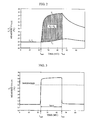
- Fig. 2 shows the chronological variation of the measured values of the temperature T 1 at the portion of the block in contact with the body surface and the temperature T 2 at the point on the block away from the body-surface contact position.
- Fig. 3 shows the chronological variation of the measured value of a temperature T 3 measured by a radiation temperature detector.
- the temperature T 3 measured is that due to the radiation from the body surface, this sensor can more sensitively react to temperature changes than other sensors. Because radiation heat propagates as an electromagnetic wave, it can transmit temperature changes instantaneously.
- contact start time t start and contact end time tend of contact between the block and body surface can be detected based on a change in temperature T 3 .
- a temperature threshold value is set as shown in Fig. 3, it can be determined that contact start time t start is when the temperature threshold value is exceeded, and contact end time tend is when the measured temperature drops below the temperature threshold value.
- the temperature threshold value may be set at 32°C, for example.
- T b 1+ c ⁇ exp( a ⁇ t ) + d
- T temperature
- t time
- the measured value can be approximated by determining factors a, b, c, and d by the non-linear least-squares method.
- T is integrated between time t start and time tend to obtain a value S 1 .
- an integrated value S 2 is calculated from the T 2 measured value.
- (S 1 - S 2 ) becomes larger with increasing finger contact time t cont ( t end - tstart).
- a 5 /(t cont ⁇ (S 1 - S 2 )) is designated as a parameter X 5 indicating the volume of blood flow, where a 5 is a proportionality coefficient.
- the measured quantities necessary for the determination of blood glucose concentration by the aforementioned model are the room temperature (ambient temperature), body surface temperature, temperature changes in the block in contact with the body surface, the temperature due to radiation from the body surface, and the absorbance of at least two wavelengths.
- Fig. 4 shows the relationships between the measured values provided by various sensors and the parameters derived therefrom.
- a block is brought into contact with the body surface, and chronological changes in the two kinds of temperatures T 1 and T 2 are measured by two temperature sensors provided at two locations of the block. Separately, the radiation temperature T 3 on the body surface and the room temperature T 4 are measured.
- Absorbance A 1 and A 2 are measured at at least two wavelengths related to the absorption of hemoglobin.
- the temperatures T 1 , T 2 , T 3 , and T 4 provide parameters related to the volume of blood flow.
- the temperature T 3 provides a parameter related to the amount of heat transferred by radiation.
- the temperatures T 3 and T 4 provide parameters related to the amount of heat transferred by convection.
- Absorbance A 1 provides a parameter relating to hemoglobin concentration.
- Absorbance A 1 and A 2 provide parameters relating to hemoglobin oxygen saturation.
- Fig. 5 shows a top plan view of the non-invasive blood sugar level measuring apparatus according to the invention. While in this example the skin on the ball of the fingertip is used as the body surface, other parts of the body surface may be used.
- an operating portion 11 On the upper surface of the apparatus are provided an operating portion 11, a measurement portion 12 where the finger to be measured is to be placed, and a display portion 13 for displaying the result of measurement, the state of the apparatus, measured values, and so on.
- the operating portion 11 includes four push buttons 11a to 11d for operating the apparatus.
- the measurement portion 12 has a cover 14 which, when opened (as shown), reveals a finger rest portion 15 with an oval periphery disposed within a finger rest guide 36.
- the finger rest portion 15 accommodates an opening end 16 of a radiation temperature sensor portion, a contact temperature sensor portion 17, and an optical sensor portion 18.
- Fig. 6 shows the operation procedure for the apparatus.
- the LCD displays "WARMING UP,” during which the electronic circuitry in the apparatus is warmed up.
- a check program is activated to automatically check the electronic circuitry.
- the LCD portion displays "PLACE FINGER.”
- the LCD portion displays a countdown.
- the LCD portion displays "RELEASE FINGER.”
- the LCD displays "DATA PROCESSING,” followed by the display of a blood sugar level.
- the thus displayed blood sugar level is stored in an IC card, together with the date and time.
- the subject reads the displayed blood sugar level and then presses a button in the operation portion. Approximately one minute later, the LCD portion displays "PLACE FINGER,” indicating that the apparatus is now ready for the next measurement.
- Fig. 7 shows the details of the measurement portion.
- Fig. 7(a) is a top plan view
- (b) is a cross section taken along line XX of (a)
- (c) is a cross section taken along YY of (a).
- the temperature sensors include a thermistor 23, which is an adjacent temperature detector with respect to the measured portion for measuring the temperature of the plate 21.
- thermistor 24 which is an indirect temperature detector with respect to the measured portion for measuring the temperature of a portion of the heat-conducting member away from the plate 21 by a certain distance.
- An infrared lens 25 is disposed inside the apparatus at such a position that the measured portion (ball of the finger) placed on the finger rest portion 15 can be seen through the lens.
- a pyroelectric detector 27 via an infrared radiation-transmitting window 26.
- Another thermistor 28 is disposed near the pyroelectric detector 27.
- the temperature sensor portion of the measurement portion has four temperature sensors, and they measure four kinds of temperatures as follows: (1) Temperature on the finger surface (thermistor 23): T 1 . (2) Temperature of the heat-conducting member (thermistor 24): T 2 . (3) Temperature of radiation from the finger (pyroelectric detector 27): T 3 . (4) Room temperature (thermistor 28): T 4 .
- Fig. 8 shows the details of the finger rest portion and a finger rest guide.
- Fig. 8(a) is a top plan view
- Fig. 8(b) is a cross section taken along line XX of (a).
- finger 37 is placed on the finger rest portion 15 during measurement.
- the movement of the finger is as follows. First, the apparatus is located in front of the subject in the direction as shown in Fig. 5, and then the finger is horizontally moved while maintaining its height to approximately the height of the finger rest portion 15, until the finger is placed on the finger rest portion 15 for measurement. In this way, the finger comes into contact with the finger rest portion 15 and the plate 21 of the contact temperature sensor portion, as shown.
- the finger rest guide 36 serves as a visual guide when the finger is moved for placement, so that substantially the same position of the ball of the finger can be measured each time the finger is placed.
- the guide 36 has an oval shape similar to the shape of the finger and is slightly larger than the finger.
- the guide is disposed around the finger rest portion 15 such that it is not in contact with the finger when the finger is placed, as shown in Fig. 8(b).
- the finger rest guide 36 which does not come into contact with the finger, can guide the finger to the finger rest 15 without permitting the heat of the finger to be transferred to the finger rest guide 36.
- the material for the finger rest guide 36 is not particularly limited, and vinyl chloride, ABS resin, and so on can be used, for example.
- the guide may be either assembled inside the sensor portion of the external casing of the apparatus, or formed integrally with the sensor portion.
- the size of the finger rest guide 36 may be 20 to 30 mm in external diameter across the width direction of the finger, and 40 to 60 mm in external diameter along the lengthwise direction of the finger.
- a groove with a depth of approximately 3 to 5 mm may be provided between the finger rest guide 36 and the finger rest portion 15.
- the finger rest guide 36 has a thermal conductivity similar to that of air
- the thermal conductivity of the finger rest guide 36, which comes into contact with the finger may be substantially equal to or smaller than that of air.
- the material of the finger rest guide 36 should have a low thermal conductivity within a range of ⁇ 15% of that of air. This is due to the fact that it is preferable to measure the finger in a state that is as close to the state in which the finger is placed in air.
- the material with a thermal conductivity close to that of air includes polyethylene foam (0.027 W/m.k), for example. However, the measurement accuracy would not be greatly affected if materials with a thermal conductivity of less than 0.1 W/m ⁇ k is used.
- Figs. 9 and 10 show examples of the finger rest guide 36 made of materials having thermal conductivities similar to that of air.
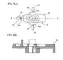
- Fig. 9 shows an example of the finger rest guide of a finger-contact type.
- Fig. 9(a) is a top plan view
- Fig. 9(b) is a cross section taken along line XX of (a).
- the finger rest guide shown in Fig. 9 includes a vertical finger rest guide 36a made of a low-thermal conductivity material, in addition to the guide 36.
- the vertical finger rest guide surrounds the finger rest portion 15 and is positioned to be opposite the ball of the finger.
- the vertical finger rest guide 36a abuts the tip of the finger and positions the finger lengthwise.
- vertical finger rest guide 36b or 36c may be added, such that the finger can be positioned in the width direction of the finger.
- These vertical finger rest guides may be adapted to be movable laterally or lengthwise, such that they can be adjusted to conform to the position of the position of the ball of the finger of each subject.
- an actuation mechanism comprises a groove 38 for moving the finger rest guides 36a, 36b, and 36c laterally or longitudinally.
- the groove 38 there are provided a number of notches for positioning and securing the finger rest guides within the range of motion.
- the finger rest guides are positioned and secured as a notch 39 fixed or integrally formed with the finger rest guides fit into the notches.
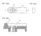
- Fig. 10 shows another example of the finger-contact type finger rest guide.
- Fig. 10(a) is a top plan view
- (b) is a cross section taken along line XX of (a)
- (c) is a side view.
- a low thermal conductivity material having a thermal conductivity that is approximately similar to that of air is used.
- the finger rest guide 36 itself has a depression that roughly conforms to the shape of the finger. Thus, by placing the finger in the depression, the ball of the finger can be positioned with respect to the finger rest portion.
- finger rest guide 36 can thus improve the situation where an accurate placement of the ball of the finger on the finger rest portion 15 is prevented by the finger rest portion 15 being covered entirely by the fingertip. Thus, the finger can be more easily placed.
- the optical sensor portion 18 will be described.
- the optical sensor portion measures the hemoglobin concentration and hemoglobin oxygen saturation for obtaining the oxygen supply amount.
- absorbance must be measured at at least two wavelengths.
- Fig. 7(c) shows an example of an arrangement for performing the two-wavelength measurement using two light sources 33 and 34 and one detector 35.
- the optical fiber 31 is for irradiating light
- the optical fiber 32 is for receiving light.
- the optical fiber 31 is connected to branch fibers 31a and 31b at the ends of which light-emitting diodes 33 and 34 with two different wavelengths are provided.
- a photodiode 35 At the end of the optical fiber 32, there is provided a photodiode 35.
- the light-emitting diode 33 emits light of a wavelength 810 nm.
- the light-emitting diode 34 emits light of a wavelength 950 nm.
- the wavelength 810 nm is the iso-absorption wavelength at which the molar absorption coefficients of oxy-hemoglobin and reduced (deoxy-) hemoglobin are equal.
- the wavelength 950 nm is the wavelength at which the difference in molar absorption coefficients between the oxy-hemoglobin and the reduced hemoglobin is large.
- the two light-emitting diodes 33 and 34 emit light in a time-divided manner.
- the light emitted by the light-emitting diodes 33 and 34 is irradiated via the light-emitting optical fiber 31 onto the finger of the subject.
- the light with which the finger is irradiated is reflected by the finger skin, incident on the light-receiving optical fiber 32, and then detected by the photodiode 35.
- the light with which the finger is irradiated is reflected by the finger skin, some of the light penetrates through the skin and into the tissue, and is then absorbed by the hemoglobin in the blood flowing in capillary blood vessels.
- the measurement data obtained by the photodiode 35 is reflectance R, and the absorbance is approximated by log (1/R). Irradiation is conducted with light of the wavelengths 810 nm and 950 nm, and R is measured for each, and then log (1/R) is calculated, thereby measuring absorbance A 1 for wavelength 810 nm and absorbance A 2 for wavelength 950 nm.
- absorbance A 1 and A 2 are expressed by the following equations:
- a Hb (810 nm) and A Hb (950 nm), and A HbO2 (810 nm) and A HbO2 (950 nm) are molar absorption coefficients of reduced hemoglobin and oxy-hemoglobin, respectively, and are known at the respective wavelengths. Sign a is a proportional coefficient.
- hemoglobin concentration and hemoglobin oxygen saturation are measured by measuring absorbance at two wavelengths, it is possible to reduce the influence of interfering components and increase measurement accuracy by measuring at three or more wavelengths.
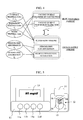
- Fig. 11 is a conceptual chart illustrating the flow of data processing in the apparatus.
- the apparatus according to the present example is equipped with five sensors, namely thermistor 23, thermistor 24, pyroelectric detector 27, thermistor 28 and photodiode 35.
- the photodiode 35 measures the absorbance at wavelength 810 nm and the absorbance at wavelength 950 nm. Thus, six kinds of measurement values are fed to the apparatus.
- normalized parameters are calculated from mean values and standard deviations of parameters x i obtained for each patient from actual data from large numbers of able-bodied people and diabetic patients.
- Calculations are conducted to convert the above five normalized parameters into a glucose concentration to be eventually displayed.
- Programs necessary for computations are stored in the ROM built inside the microprocessor in the apparatus. Memory areas necessary for computations are ensured in a RAM built inside the apparatus. The results of the calculations are displayed on the LCD portion.
- the ROM stores, as a constituent element of the program necessary for the computations, a function for determining glucose concentration C in particular.
- the function is defined as follows.
- the regression equation (1) indicating the relationship between the glucose concentration C and the normalized parameters X 1 , X 2 , X 3 , X 4 and X 5 is formulated.
- equation (1) yields equation (4) thus:
- Constant term a 0 is obtained by means of equation (4).
- the normalized parameters X 1 to X 5 obtained from the measured values are substituted into regression equation (1) to calculate the glucose concentration C.
- the coefficients in equation (1) are determined in advance based on a large quantity of data obtained from able-bodied persons and diabetic patients.
- X 1 to X 5 are the results of normalization of parameters x 1 to x 5 . Assuming the distribution of the parameters is normal, 95% of the normalized parameters take on values between -2 and +2.
- a blood sample is reacted with a reagent and the amount of resultant electrons is measured to determine blood sugar level.
- Fig. 9 shows a chart plotting on the vertical axis the values of glucose concentration calculated by the inventive method and on the horizontal axis the values of glucose concentration measured by the enzymatic electrode method, based on measurement values obtained from a plurality of patients.
- the parameters relating to blood hemoglobin concentration and blood hemoglobin oxygen saturation are obtained by spectroscopically measuring the hemoglobin in blood.
- the hemoglobin concentration is stable in persons without such symptoms as anemia, bleeding or erythrocytosis.
- the hemoglobin concentration is normally in the range between 13 to 18 g/dL for males and between 12 to 17 g/dL for females, and the range of variation of hemoglobin concentration from the normal values is 5 to 6%.
- the weight of the term in the aforementioned formula for calculating blood sugar level is smaller than other terms. Therefore, the hemoglobin concentration can be treated as a constant without greatly lowering the measurement accuracy.
- the hemoglobin oxygen saturation is stable between 97 to 98% if the person is undergoing aerial respiration at atmospheric pressure, at rest and in a relaxed state.
- the hemoglobin concentration and the hemoglobin oxygen saturation can be treated as constants, and the oxygen supply amount can be determined from the product of the hemoglobin concentration constant, the hemoglobin oxygen saturation constant and the blood flow volume.
- the sensor arrangement for measuring blood sugar level can be simplified by removing the optical sensors, for example. Further, by eliminating the time necessary for optical measurement and the processing thereof, the procedure for blood sugar level measurement can be accomplished in less time.
- the hemoglobin oxygen saturation takes on a stable value when at rest, in particular, by treating the hemoglobin concentration and hemoglobin oxygen saturation as constants, the measurement accuracy for blood sugar level measurement when at rest can be increased, and the procedure blood sugar level measurement can be accomplished in less time.
- “when at rest” herein is meant the state in which the test subject has been either sitting on a chair or lying and thus moving little for approximately five minutes.
- the hemoglobin concentration and hemoglobin oxygen saturation shown in Fig. 4 are not measured but treated as constants. Therefore, as shown in Fig. 19, the measurement portion of the present embodiment has the structure of the measurement portion of the earlier embodiment shown in Fig. 7 from which the light sources 33 and 34, photodiode 35 and optical fibers 31 and 32 are removed.
- Parameters used in the present embodiment are parameter x 1 proportional to heat radiation, parameter x 2 related to heat convection, and parameter x 3 proportional to the oxygen supply amount (hereafter, parameter proportional to oxygen supply amount will be indicated as x 3 ).
- Fig. 20 shows a functional block diagram of the apparatus according to the embodiment.
- the apparatus runs on battery 41.
- a signal measured by sensor portion 48 including a temperature sensor is fed to analog/digital converters 44 (AD1 to AD4) provided for individual signals and is converted into a digital signal.
- Analog/digital converters AD1 to AD4, LCD 13 and RAM 42 are peripheral circuits for microprocessor 55. They are accessed by the microprocessor 55 via bus line 46.
- the push buttons 11a to 11d are connected to microprocessor 55.
- the microprocessor 55 includes the ROM for storing software. By pressing the buttons 11a to 11d, external instructions can be entered into microprocessor 55.
- the ROM 47 included in the microprocessor 55 stores a program necessary for computations, i.e., it has the function of an arithmetic unit.
- the microprocessor 55 further includes a hemoglobin concentration constant storage portion 50 for storing hemoglobin concentration constants, and a hemoglobin oxygen saturation constant storage portion 49 for storing hemoglobin oxygen saturation constants.
- the computing program calls optimum constants from the hemoglobin concentration storage portion 50 and hemoglobin oxygen saturation constant storage portion 49 and perform calculations.
- a memory area necessary for computations is ensured in the RAM 42 similarly incorporated into the apparatus. The result of computations is displayed on the LCD portion.
- the ROM stores, as a constituent element of the program necessary for the computations, a function for determining glucose concentration C in particular.
- the function is defined as follows.
- Constant term a 0 is obtained by means of equation (11).
- the normalized parameters X 1 to X 3 obtained from the measured values are substituted into regression equation (8) to calculate the glucose concentration C.
- the coefficients in equation (8) are determined in advance based on a large quantity of data obtained from able-bodied persons and diabetic patients.
- X 1 to X 3 are the results of normalization of parameters x 1 to x 3 . Assuming the distribution of the parameters is normal, 95% of the normalized parameters take on values between -2 and +2.
- Fig. 21 shows a chart plotting on the vertical axis the values of glucose concentration calculated by the inventive method and on the horizontal axis the values of glucose concentration measured by the enzymatic electrode method, based on measurement values obtained from a plurality of patients.
Abstract
Blood sugar levels are measured non-invasively based on temperature
measurement. Non-invasively measured blood sugar level values obtained by a
temperature measurement scheme are corrected by blood oxygen saturation and
blood flow volume, thereby stabilizing the measurement data. A guide is
provided for guiding an analyte to a measurement portion.
Description
The present application claims priority from Japanese application JP
2004-040493 filed in February 17, 2004, the content of which is hereby incorporated by reference of this application.
The present invention relates to a non-invasive blood sugar level
measuring apparatus for measuring glucose concentration in a living body without
blood sampling.
Hilson et al. report facial and sublingual temperature changes in diabetics
following intravenous glucose injection (Non-Patent Document 1). Scott et al.
discuss the issue of diabetics and thermoregulation (Non-Patent Document 2).
Based on such researches, Cho et al. suggests a method and apparatus for
determining blood glucose concentration by temperature measurement without
requiring the collection of a blood sample (Patent Documents 1 and 2).
Various other attempts have been made to determine glucose concentration
without blood sampling. For example, a method has been suggested (Patent
Document 3) whereby a measurement site is irradiated with near-infrared light of
three wavelengths, and the intensity of transmitted light as well as the
temperature of the living body is detected. Then, a representative value of the
second-order differentiated values of absorbance is calculated, and the
representative value is corrected in accordance with the difference between the
living body temperature and a predetermined reference temperature. A blood
sugar level corresponding to the thus corrected representative value is then
determined. An apparatus is also provided (Patent Document 4) whereby a
measurement site is heated or cooled while monitoring the living body
temperature. The degree of attenuation of light based on light irradiation is
measured at the moment of temperature change so that the glucose concentration
responsible for the temperature-dependency of the degree of light attenuation can
be measured. Further, an apparatus is reported (Patent Document 5) whereby an
output ratio between reference light and the light transmitted by an irradiated
sample is taken, and then a glucose concentration is calculated by a linear
expression of the logarithm of the output ratio and the living body temperature.
Glucose (blood sugar) in blood is used for glucose oxidation reaction in
cells to produce necessary energy for the maintenance of a living body. In the
basal metabolism state, in particular, most of the produced energy is converted
into heat energy for the maintenance of body temperature. Thus, it can be
expected that there is some relationship between blood glucose concentration and
body temperature. However, as is evident from the way sicknesses cause fever,
the body temperature also varies due to factors other than blood glucose
concentration. While methods have been proposed to determine blood glucose
concentration by temperature measurement without blood sampling, they lack
sufficient accuracy.
It is the object of the invention to provide a method and apparatus for
determining blood glucose concentration with high accuracy based on temperature
data of a subject without blood sampling.
Blood sugar is delivered to the cells throughout the human body via the
blood vessel system, particularly the capillary blood vessels. In the human body,
complex metabolic pathways exist. Glucose oxidation is a reaction in which,
fundamentally, blood sugar reacts with oxygen to produce water, carbon dioxide,
and energy. Oxygen herein refers to the oxygen delivered to the cells via blood.
The amount of oxygen supply is determined by the blood hemoglobin
concentration, the hemoglobin oxygen saturation, and the volume of blood flow.
On the other hand, the heat produced in the body by glucose oxidation is
dissipated from the body by convection, heat radiation, conduction, and so on.
On the assumption that the body temperature is determined by the balance
between the amount of energy produced in the body by glucose burning, namely
heat production, and heat dissipation such as mentioned above, we set up the
following model:
The inventors have achieved the present invention after realizing that
blood sugar levels can be accurately determined on the basis of the results of
measuring the temperature of the body surface and parameters relating to oxygen
concentration in blood and blood flow volume, in accordance with the
aforementioned model. The parameters can be measured from a part of the
human body, such as the fingertip. Parameters relating to convection and
radiation can be determined by carrying out thermal measurements on the
fingertip. Parameters relating to blood hemoglobin concentration and blood
hemoglobin oxygen saturation can be obtained by spectroscopically measuring
blood hemoglobin and determining the ratio of hemoglobin bound with oxygen to
hemoglobin not bound with oxygen. With regard to the parameters relating to
blood hemoglobin concentration and blood hemoglobin oxygen saturation,
measurement accuracy would not be significantly lowered if pre-stored constants
are employed rather than taking measurements. The parameter relating to the
volume of blood flow can be determined by measuring the amount of heat transfer
from the skin.
In one aspect, the invention provides a blood sugar level measuring
apparatus comprising:
In another aspect, the invention provides a blood sugar level measuring
apparatus comprising:
In yet another aspect, the invention provides a blood sugar level
measuring apparatus comprising:
The aforementioned guide may be disposed such that it surrounds the
body-surface contact portion. Further, the guide may include a stopper for
positioning the subject. The stopper may be formed by a first stopper for
defining the position of the tip of the subject, and a second and a third stopper for
defining the position of the subject along the thickness thereof. The position of
the stopper may be variable. Preferably, the stopper has a heat conductivity of
not more than 0.1 W/m·k. The guide may comprise a depression that conforms
to the shape of the subject.
In accordance with the invention, blood sugar levels can be determined in
an non-invasive measurement with the same level of accuracy with that of the
conventional invasive methods.
The invention will now be described by way of preferred embodiments
thereof with reference made to the drawings. For ease of understanding, similar
reference characters refer to similar functional portions in all figures of the
drawing.
Initially, the above-mentioned model will be described in more specific
terms. Regarding the amount of heat dissipation, convective heat transfer, which
is one of the main causes of heat dissipation, is related to temperature difference
between the ambient (room) temperature and the body-surface temperature. The
amount of heat dissipation due to radiation, another main cause of dissipation, is
proportional to the fourth power of the body-surface temperature according to the
Stefan-Boltzmann law. Thus, it can be seen that the amount of heat dissipation
from the human body is related to the room temperature and the body-surface
temperature. Another major factor related to the amount of heat production, the
oxygen supply amount, is expressed as the product of hemoglobin concentration,
hemoglobin oxygen saturation, and blood flow volume.
The hemoglobin concentration can be measured based on the absorbance
of light at the wavelength (iso-absorption wavelength) at which the molar
absorption coefficient of the oxy-hemoglobin and that of the reduced
(deoxygenated) hemoglobin are equal. The hemoglobin oxygen saturation can be
measured by measuring the absorbance of the iso-absorption wavelength and at
least one other wavelength at which the ratio of the molar absorption coefficient
of the oxy-hemoglobin to that of the reduced (deoxygenated) hemoglobin is
known, and then solving simultaneous equations. Thus, the hemoglobin
concentration and the hemoglobin oxygen saturation can be obtained by
measuring absorbance at at least two wavelengths.
The rest is the blood flow volume, which can be measured by various
methods. One example will be described below.
Fig. 1 shows a model for the description of the transfer of heat from the
body surface to a solid block with a certain heat capacity as the block is brought
into contact with the body surface for a certain time and then separated. The
block is made of resin such as plastic or vinyl chloride. In the illustrated
example, attention will be focused on the chronological variation of a temperature
T1 of a portion of the block in contact with the body surface, and the
chronological variation of a temperature T2 at a point on the block away from the
body surface. The blood flow volume can be estimated by monitoring mainly
the chronological variation of the temperature T2 (at the spatially distant point on
the block). The details will be described later.
Before the block comes into contact with the body surface, the
temperatures T1 and T2 at the two points of the block are equal to the room
temperature Tr. When a body-surface temperature Ts is higher than the room
temperature Tr, the temperature T1 swiftly rises as the block comes into contact
with the body surface, due to the transfer of heat from the skin, and it approaches
the body-surface temperature Ts. On the other hand, the temperature T2, which
is lower than the temperature T1 due to the dissipation of the heat conducted
through the block from its surface, rises more gradually than the temperature T1.
The chronological variation of the temperatures T1 and T2 depends on the amount
of heat transferred from the body surface to the block, which in turn depends on
the blood flow volume in the capillary blood vessels under the skin. If the
capillary blood vessels are regarded as a heat exchanger, the coefficient of heat
transfer from the capillary blood vessels to the surrounding cell tissues is given as
a function of the blood flow volume. Thus, by measuring the amount of heat
transfer from the body surface to the block by monitoring the chronological
variation of the temperatures T1 and T2, the amount of heat transmitted from the
capillary blood vessels to the cell tissues can be estimated, which in turn makes it
possible to estimate the blood flow volume.
Fig. 2 shows the chronological variation of the measured values of the
temperature T1 at the portion of the block in contact with the body surface and the
temperature T2 at the point on the block away from the body-surface contact
position. As the block comes into contact with the body surface, T1 swiftly
rises, and it gradually drops as the block is brought out of contact.
Fig. 3 shows the chronological variation of the measured value of a
temperature T3 measured by a radiation temperature detector. As the
temperature T3 measured is that due to the radiation from the body surface, this
sensor can more sensitively react to temperature changes than other sensors.
Because radiation heat propagates as an electromagnetic wave, it can transmit
temperature changes instantaneously. Thus, as shown in Fig. 7, reference to
which will be made below, by providing the radiation temperature detector near
the position where the block is in contact with the body surface in order to detect
the radiant heat from the body surface, contact start time tstart and contact end
time tend of contact between the block and body surface can be detected based on
a change in temperature T3. For example, when a temperature threshold value is
set as shown in Fig. 3, it can be determined that contact start time tstart is when
the temperature threshold value is exceeded, and contact end time tend is when the
measured temperature drops below the temperature threshold value. The
temperature threshold value may be set at 32°C, for example.
Then, the T1 measured value between tstart and tend is approximated by an
S curve, such as a logistic curve. A logistic curve is expressed by the following
equation:
T = b 1+c ×exp(a ×t ) + d
where T is temperature, and t is time.
The measured value can be approximated by determining factors a, b, c,
and d by the non-linear least-squares method. For the resultant approximate
expression, T is integrated between time tstart and time tend to obtain a value S1.
Similarly, an integrated value S2 is calculated from the T2 measured value.
The smaller the (S1 - S2) is, the larger the amount of transfer of heat from the
finger surface to the position of T2. (S1 - S2) becomes larger with increasing
finger contact time tcont (=tend - tstart). Thus, a5/(tcont × (S1 - S2)) is designated as
a parameter X5 indicating the volume of blood flow, where a5 is a proportionality
coefficient.
It will be seen from the above description that the measured quantities
necessary for the determination of blood glucose concentration by the
aforementioned model are the room temperature (ambient temperature), body
surface temperature, temperature changes in the block in contact with the body
surface, the temperature due to radiation from the body surface, and the
absorbance of at least two wavelengths.
Fig. 4 shows the relationships between the measured values provided by
various sensors and the parameters derived therefrom. A block is brought into
contact with the body surface, and chronological changes in the two kinds of
temperatures T1 and T2 are measured by two temperature sensors provided at two
locations of the block. Separately, the radiation temperature T3 on the body
surface and the room temperature T4 are measured. Absorbance A1 and A2 are
measured at at least two wavelengths related to the absorption of hemoglobin.
The temperatures T1, T2, T3, and T4 provide parameters related to the volume of
blood flow. The temperature T3 provides a parameter related to the amount of
heat transferred by radiation. The temperatures T3 and T4 provide parameters
related to the amount of heat transferred by convection. Absorbance A1 provides
a parameter relating to hemoglobin concentration. Absorbance A1 and A2
provide parameters relating to hemoglobin oxygen saturation.
Hereafter, an example of the apparatus for non-invasively measuring
blood sugar levels according to the principle of the invention will be described.
Fig. 5 shows a top plan view of the non-invasive blood sugar level
measuring apparatus according to the invention. While in this example the skin
on the ball of the fingertip is used as the body surface, other parts of the body
surface may be used.
On the upper surface of the apparatus are provided an operating portion 11,
a measurement portion 12 where the finger to be measured is to be placed, and a
display portion 13 for displaying the result of measurement, the state of the
apparatus, measured values, and so on. The operating portion 11 includes four
push buttons 11a to 11d for operating the apparatus. The measurement portion
12 has a cover 14 which, when opened (as shown), reveals a finger rest portion 15
with an oval periphery disposed within a finger rest guide 36. The finger rest
portion 15 accommodates an opening end 16 of a radiation temperature sensor
portion, a contact temperature sensor portion 17, and an optical sensor portion 18.
Fig. 6 shows the operation procedure for the apparatus. As a button in
the operation portion is pressed and the apparatus is turned on, the LCD displays
"WARMING UP," during which the electronic circuitry in the apparatus is
warmed up. Simultaneously, a check program is activated to automatically
check the electronic circuitry. After the end of "WARMING UP," the LCD
portion displays "PLACE FINGER." As the finger is placed on the finger rest
portion, the LCD portion displays a countdown. When the countdown is over,
the LCD portion displays "RELEASE FINGER." As the finger is released from
the finger rest, the LCD displays "DATA PROCESSING," followed by the display
of a blood sugar level. The thus displayed blood sugar level is stored in an IC
card, together with the date and time. The subject reads the displayed blood
sugar level and then presses a button in the operation portion. Approximately
one minute later, the LCD portion displays "PLACE FINGER," indicating that the
apparatus is now ready for the next measurement.
Fig. 7 shows the details of the measurement portion. Fig. 7(a) is a top
plan view, (b) is a cross section taken along line XX of (a), and (c) is a cross
section taken along YY of (a).
First, temperature measurement by the non-invasive blood sugar level
measuring apparatus according to the invention will be described. A thin plate
21 of a highly heat-conductive material, such as gold, is disposed on a portion
where a measured portion (ball of the finger) is to come into contact. A
bar-shaped heat-conductive member 22 made of a material with a heat
conductivity lower than that of the plate 21, such as polyvinylchloride, is
thermally connected to the plate 21 and extends into the apparatus. The
temperature sensors include a thermistor 23, which is an adjacent temperature
detector with respect to the measured portion for measuring the temperature of
the plate 21. There is also a thermistor 24, which is an indirect temperature
detector with respect to the measured portion for measuring the temperature of a
portion of the heat-conducting member away from the plate 21 by a certain
distance. An infrared lens 25 is disposed inside the apparatus at such a position
that the measured portion (ball of the finger) placed on the finger rest portion 15
can be seen through the lens. Below the infrared lens 25, there is disposed a
pyroelectric detector 27 via an infrared radiation-transmitting window 26.
Another thermistor 28 is disposed near the pyroelectric detector 27.
Thus, the temperature sensor portion of the measurement portion has four
temperature sensors, and they measure four kinds of temperatures as follows:
(1) Temperature on the finger surface (thermistor 23): T1. (2) Temperature of
the heat-conducting member (thermistor 24): T2. (3) Temperature of radiation
from the finger (pyroelectric detector 27): T3. (4) Room temperature (thermistor
28): T4.
Fig. 8 shows the details of the finger rest portion and a finger rest guide.
Fig. 8(a) is a top plan view, and Fig. 8(b) is a cross section taken along line XX
of (a). As mentioned in the description of the operation procedure for the
apparatus, finger 37 is placed on the finger rest portion 15 during measurement.
Specifically, the movement of the finger is as follows. First, the apparatus is
located in front of the subject in the direction as shown in Fig. 5, and then the
finger is horizontally moved while maintaining its height to approximately the
height of the finger rest portion 15, until the finger is placed on the finger rest
portion 15 for measurement. In this way, the finger comes into contact with the
finger rest portion 15 and the plate 21 of the contact temperature sensor portion,
as shown.
The finger rest guide 36 serves as a visual guide when the finger is moved
for placement, so that substantially the same position of the ball of the finger can
be measured each time the finger is placed. The guide 36 has an oval shape
similar to the shape of the finger and is slightly larger than the finger. The guide
is disposed around the finger rest portion 15 such that it is not in contact with the
finger when the finger is placed, as shown in Fig. 8(b). Thus, the finger rest
guide 36, which does not come into contact with the finger, can guide the finger
to the finger rest 15 without permitting the heat of the finger to be transferred to
the finger rest guide 36. Accordingly, the material for the finger rest guide 36 is
not particularly limited, and vinyl chloride, ABS resin, and so on can be used, for
example. The guide may be either assembled inside the sensor portion of the
external casing of the apparatus, or formed integrally with the sensor portion.
The size of the finger rest guide 36 may be 20 to 30 mm in external diameter
across the width direction of the finger, and 40 to 60 mm in external diameter
along the lengthwise direction of the finger. A groove with a depth of
approximately 3 to 5 mm may be provided between the finger rest guide 36 and
the finger rest portion 15.
If the finger rest guide 36 has a thermal conductivity similar to that of air,
the finger 37 can be brought into contact with the finger rest guide 36, so that the
finger can be physically positioned. The thermal conductivity of the finger rest
guide 36, which comes into contact with the finger, may be substantially equal to
or smaller than that of air. Preferably, the material of the finger rest guide 36
should have a low thermal conductivity within a range of ±15% of that of air.
This is due to the fact that it is preferable to measure the finger in a state that is
as close to the state in which the finger is placed in air. The material with a
thermal conductivity close to that of air includes polyethylene foam (0.027
W/m.k), for example. However, the measurement accuracy would not be greatly
affected if materials with a thermal conductivity of less than 0.1 W/m·k is used.
Figs. 9 and 10 show examples of the finger rest guide 36 made of materials
having thermal conductivities similar to that of air.
Fig. 9 shows an example of the finger rest guide of a finger-contact type.
Fig. 9(a) is a top plan view, and Fig. 9(b) is a cross section taken along line XX
of (a). The finger rest guide shown in Fig. 9 includes a vertical finger rest guide
36a made of a low-thermal conductivity material, in addition to the guide 36.
The vertical finger rest guide surrounds the finger rest portion 15 and is
positioned to be opposite the ball of the finger. When the finger is placed on the
finger rest portion 15, the vertical finger rest guide 36a abuts the tip of the finger
and positions the finger lengthwise. Preferably, vertical finger rest guide 36b or
36c may be added, such that the finger can be positioned in the width direction of
the finger. These vertical finger rest guides may be adapted to be movable
laterally or lengthwise, such that they can be adjusted to conform to the position
of the position of the ball of the finger of each subject. The larger the area of
contact of the vertical finger rest guides 36a, 36b, and 36c with the finger, the
closer the thermal conductivity of the material should preferably be to that of air.
In the example shown in Fig. 9, an actuation mechanism is provided that
comprises a groove 38 for moving the finger rest guides 36a, 36b, and 36c
laterally or longitudinally. In the groove 38, there are provided a number of
notches for positioning and securing the finger rest guides within the range of
motion. The finger rest guides are positioned and secured as a notch 39 fixed or
integrally formed with the finger rest guides fit into the notches.
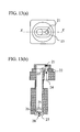
Fig. 10 shows another example of the finger-contact type finger rest guide.
Fig. 10(a) is a top plan view, (b) is a cross section taken along line XX of (a), and
(c) is a side view. For the finger rest guide 36, a low thermal conductivity
material having a thermal conductivity that is approximately similar to that of air
is used. The finger rest guide 36 itself has a depression that roughly conforms to
the shape of the finger. Thus, by placing the finger in the depression, the ball of
the finger can be positioned with respect to the finger rest portion.
Other shapes of the finger rest guide may be employed as long as the
material of the finger rest guide has a thermal conductivity similar to that of air.
The finger rest guide 36 can thus improve the situation where an accurate
placement of the ball of the finger on the finger rest portion 15 is prevented by
the finger rest portion 15 being covered entirely by the fingertip. Thus, the
finger can be more easily placed.
The optical sensor portion 18 will be described. The optical sensor
portion measures the hemoglobin concentration and hemoglobin oxygen
saturation for obtaining the oxygen supply amount. For measuring the
hemoglobin concentration and hemoglobin oxygen saturation, absorbance must be
measured at at least two wavelengths. Fig. 7(c) shows an example of an
arrangement for performing the two-wavelength measurement using two light
sources 33 and 34 and one detector 35.
Inside the optical sensor portion 18, there are disposed the end portions of
two optical fibers 31 and 32. The optical fiber 31 is for irradiating light, and the
optical fiber 32 is for receiving light. As shown in Fig. 7(c), the optical fiber 31
is connected to branch fibers 31a and 31b at the ends of which light-emitting
diodes 33 and 34 with two different wavelengths are provided. At the end of the
optical fiber 32, there is provided a photodiode 35. The light-emitting diode 33
emits light of a wavelength 810 nm. The light-emitting diode 34 emits light of a
wavelength 950 nm. The wavelength 810 nm is the iso-absorption wavelength at
which the molar absorption coefficients of oxy-hemoglobin and reduced (deoxy-)
hemoglobin are equal. The wavelength 950 nm is the wavelength at which the
difference in molar absorption coefficients between the oxy-hemoglobin and the
reduced hemoglobin is large.
The two light-emitting diodes 33 and 34 emit light in a time-divided
manner. The light emitted by the light-emitting diodes 33 and 34 is irradiated
via the light-emitting optical fiber 31 onto the finger of the subject. The light
with which the finger is irradiated is reflected by the finger skin, incident on the
light-receiving optical fiber 32, and then detected by the photodiode 35. When
the light with which the finger is irradiated is reflected by the finger skin, some
of the light penetrates through the skin and into the tissue, and is then absorbed
by the hemoglobin in the blood flowing in capillary blood vessels. The
measurement data obtained by the photodiode 35 is reflectance R, and the
absorbance is approximated by log (1/R). Irradiation is conducted with light of
the wavelengths 810 nm and 950 nm, and R is measured for each, and then log
(1/R) is calculated, thereby measuring absorbance A1 for wavelength 810 nm and
absorbance A2 for wavelength 950 nm.
When the reduced hemoglobin concentration is [Hb], and the
oxy-hemoglobin concentration is [HbO2], absorbance A1 and A2 are expressed by
the following equations:


AHb (810 nm) and AHb (950 nm), and AHbO2 (810 nm) and AHbO2 (950 nm)
are molar absorption coefficients of reduced hemoglobin and oxy-hemoglobin,
respectively, and are known at the respective wavelengths. Sign a is a
proportional coefficient. Based on the above equations, the hemoglobin
concentration ([Hb] + [HbO2]) and the hemoglobin oxygen saturation {[HbO2] /([Hb]
+ [HbO2])} can be determined as follows:
[Hb ] + [HbO 2 ] = A 1 a × A HbO 2 (810nm )
[HbO 2 ][Hb ] + [HbO 2 ] = A 2 × A HbO 2 (810nm ) - A 1 × A Hb (950nm )) A 1 × (A HbO 2 (950nm ) - A Hb (950nm ))
While in the above example the hemoglobin concentration and
hemoglobin oxygen saturation are measured by measuring absorbance at two
wavelengths, it is possible to reduce the influence of interfering components and
increase measurement accuracy by measuring at three or more wavelengths.
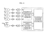
Fig. 11 is a conceptual chart illustrating the flow of data processing in the
apparatus. The apparatus according to the present example is equipped with five
sensors, namely thermistor 23, thermistor 24, pyroelectric detector 27, thermistor
28 and photodiode 35. The photodiode 35 measures the absorbance at
wavelength 810 nm and the absorbance at wavelength 950 nm. Thus, six kinds
of measurement values are fed to the apparatus.
Five kinds of analog signals are supplied via amplifiers A1 to A5 and
digitally converted by analog/digital converters AD1 to AD5. Based on the
digitally converted values, parameters xi (i=1, 2, 3, 4, 5) are calculated. The
following are specific descriptions of xi (where a1 to a5 are proportionality
coefficients):


Then, normalized parameters are calculated from mean values and
standard deviations of parameters xi obtained for each patient from actual data
from large numbers of able-bodied people and diabetic patients. A normalized
parameter Xi (where i=1, 2, 3, 4, 5) is calculated from each parameter xi
according to the following equation:
x i = x i - x i SD (x i )
where
x i : parameter
x i : mean value of the parameter
SD(x i ): standard deviation of the parameter
x i : parameter
SD(x i ): standard deviation of the parameter
Calculations are conducted to convert the above five normalized
parameters into a glucose concentration to be eventually displayed. Programs
necessary for computations are stored in the ROM built inside the microprocessor
in the apparatus. Memory areas necessary for computations are ensured in a
RAM built inside the apparatus. The results of the calculations are displayed on
the LCD portion.
The ROM stores, as a constituent element of the program necessary for
the computations, a function for determining glucose concentration C in particular.
The function is defined as follows. C is expressed by a below-indicated
equation (1), where ai (i=0, 1, 2, 3, 4, 5) is determined from a plurality of pieces
of measurement data in advance according to the following procedure:
Initially, the regression equation (1) indicating the relationship between
the glucose concentration C and the normalized parameters X1, X2, X3, X4 and X5
is formulated.

Then, the least-squares method is employed to obtain a multiple
regression equation that would minimize the error with respect to a measured
value Ci of glucose concentration according to an enzyme electrode method.
When the sum of squares of the residual is D, D is expressed by the following
equation (2):

The sum of squares of the residual D becomes minimum when partial
differentiation of equation (2) with respect to a0, a2, ..., a5 gives zero. Thus, we
have the following equations:

When the mean values of C and X1 to X5 are Cmean and X1mean to X5mean,
respectively, since Ximean=0 (i=1 to 5), equation (1) yields equation (4) thus:

The variation and covariation between the normalized parameters are
expressed by equation (5). Covariation between the normalized parameter Xi
(i=1 to 5) and C is expressed by equation (6).


Substituting equations (4), (5), and (6) into equation (3) and rearranging
yields simultaneous equations (normalized equations) (7). Solving equations (7)
yields a1 to a5.
a 1 S 11 + a 2 S 12 + a 3 S 13 + a 4 S 14 + a 5 S 15 = S 1C a 1 S 21 + a 2 S 22 + a 3 S 23 + a 4 S 24 + a 5 S 25 = S 2C a 1 S 31 + a 2 S 32 + a 3 S 33 + a 4 S 34 + a 5 S 35 = S 3C a 1 S 41 + a 2 S 42 + a 3 S 43 + a 4 S 44 + a 5 S 45 = S 4C a 1 S 51 + a 2 S 52 + a 3 S 53 + a 4 S 54 + a 5 S 55 = S 5C
Constant term a0 is obtained by means of equation (4). The thus
obtained ai (i=0, 1, 2, 3, 4, 5) is stored in ROM at the time of manufacture of the
apparatus. In actual measurement using the apparatus, the normalized
parameters X1 to X5 obtained from the measured values are substituted into
regression equation (1) to calculate the glucose concentration C.
Hereafter, an example of the process of calculating the glucose
concentration will be described. The coefficients in equation (1) are determined
in advance based on a large quantity of data obtained from able-bodied persons
and diabetic patients. The ROM in the microprocessor stores the following
formula for the calculation of glucose concentration:
C = 99.4 +18.3 × X 1 - 20.2 × X 2 - 23.7 × X 3 - 22.0 × X 4 - 25.9 × X 5
X1 to X5 are the results of normalization of parameters x1 to x5.
Assuming the distribution of the parameters is normal, 95% of the normalized
parameters take on values between -2 and +2.
In an example of measured values for an able-bodied person, substituting
normalized parameters X1=-0.06, X2=+0.04 and X3=+0.05, X4=-0.12 and
X5=+0.10 in the above equation yields C=96 mg/dL. In an example of measured
values for a diabetic patient, substituting normalized parameters X1=+1.15,
X2=-1.02, X3=-0.83, X4=-0.91 and X5=-1.24 in the equation yields C=213 mg/dL.
Hereafter, the results of measurement by the conventional enzymatic
electrode method and those by the embodiment of the invention will be described.
In the enzymatic electrode method, a blood sample is reacted with a reagent and
the amount of resultant electrons is measured to determine blood sugar level.
When the glucose concentration was 89 mg/dL according to the enzymatic
electrode method in an example of measured values for an able-bodied person,
substituting normalized parameters X1=-0.06, X2=+0.04, X3=+0.05, X4=-0.12 and
X5=+0.10 obtained by measurement at the same time according to the inventive
method into the above equation yield C=96 mg/dL. Further, when the glucose
concentration was 238 mg/dL according to the enzymatic electrode method in an
example of measurement values for a diabetic patient, substituting X1=+1.15,
X2=-1.02, X3=-0.83, X4=-0.91 and X5=-1.24 obtained by measurement at the
same time according to the inventive method yields C=213 mg/dL. From the
above results, it has been confirmed that the glucose concentration can be
accurately determined using the method of the invention.
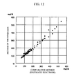
Fig. 9 shows a chart plotting on the vertical axis the values of glucose
concentration calculated by the inventive method and on the horizontal axis the
values of glucose concentration measured by the enzymatic electrode method,
based on measurement values obtained from a plurality of patients. A good
correlation is obtained by measuring the oxygen supply amount and blood flow
volume according to the invention (correlation coefficient = 0.9324).
In the above-described embodiment, the parameters relating to blood
hemoglobin concentration and blood hemoglobin oxygen saturation are obtained
by spectroscopically measuring the hemoglobin in blood. However, the
hemoglobin concentration is stable in persons without such symptoms as anemia,
bleeding or erythrocytosis. The hemoglobin concentration is normally in the
range between 13 to 18 g/dL for males and between 12 to 17 g/dL for females,
and the range of variation of hemoglobin concentration from the normal values is
5 to 6%. Further, the weight of the term in the aforementioned formula for
calculating blood sugar level is smaller than other terms. Therefore, the
hemoglobin concentration can be treated as a constant without greatly lowering
the measurement accuracy. Similarly, the hemoglobin oxygen saturation is
stable between 97 to 98% if the person is undergoing aerial respiration at
atmospheric pressure, at rest and in a relaxed state. Thus the hemoglobin
concentration and the hemoglobin oxygen saturation can be treated as constants,
and the oxygen supply amount can be determined from the product of the
hemoglobin concentration constant, the hemoglobin oxygen saturation constant
and the blood flow volume.
By treating the hemoglobin concentration and hemoglobin oxygen
saturation as constants, the sensor arrangement for measuring blood sugar level
can be simplified by removing the optical sensors, for example. Further, by
eliminating the time necessary for optical measurement and the processing thereof,
the procedure for blood sugar level measurement can be accomplished in less
time.
Because the hemoglobin oxygen saturation takes on a stable value when at
rest, in particular, by treating the hemoglobin concentration and hemoglobin
oxygen saturation as constants, the measurement accuracy for blood sugar level
measurement when at rest can be increased, and the procedure blood sugar level
measurement can be accomplished in less time. By "when at rest" herein is
meant the state in which the test subject has been either sitting on a chair or lying
and thus moving little for approximately five minutes.
Hereafter, an embodiment will be described in which the blood
hemoglobin concentration and blood hemoglobin oxygen saturation are treated as
constants. This embodiment is similar to the above-described embodiment
except that the blood hemoglobin concentration and blood hemoglobin oxygen
saturation are treated as constants, and therefore the following description mainly
concerns the differences from the earlier embodiment.
In the present embodiment, the hemoglobin concentration and hemoglobin
oxygen saturation shown in Fig. 4 are not measured but treated as constants.
Therefore, as shown in Fig. 19, the measurement portion of the present
embodiment has the structure of the measurement portion of the earlier
embodiment shown in Fig. 7 from which the light sources 33 and 34, photodiode
35 and optical fibers 31 and 32 are removed. Parameters used in the present
embodiment are parameter x1 proportional to heat radiation, parameter x2 related
to heat convection, and parameter x3 proportional to the oxygen supply amount
(hereafter, parameter proportional to oxygen supply amount will be indicated as
x3). From these parameters, normalized parameters are calculated in the manner
described above, and a glucose concentration is calculated based on the three
normalized parameters Xi (i=1, 2, 3). During data processing, the step
"CONVERSION OF OPTICAL MEASUREMENT DATA INTO NORMALIZED
PARAMETERS" (see Fig. 8), which is necessary in the previous embodiment, can
be omitted.
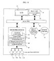
Fig. 20 shows a functional block diagram of the apparatus according to
the embodiment. The apparatus runs on battery 41. A signal measured by
sensor portion 48 including a temperature sensor is fed to analog/digital
converters 44 (AD1 to AD4) provided for individual signals and is converted into
a digital signal. Analog/digital converters AD1 to AD4, LCD 13 and RAM 42
are peripheral circuits for microprocessor 55. They are accessed by the
microprocessor 55 via bus line 46. The push buttons 11a to 11d are connected to
microprocessor 55. The microprocessor 55 includes the ROM for storing
software. By pressing the buttons 11a to 11d, external instructions can be
entered into microprocessor 55.
The ROM 47 included in the microprocessor 55 stores a program
necessary for computations, i.e., it has the function of an arithmetic unit. The
microprocessor 55 further includes a hemoglobin concentration constant storage
portion 50 for storing hemoglobin concentration constants, and a hemoglobin
oxygen saturation constant storage portion 49 for storing hemoglobin oxygen
saturation constants. After the measurement of the finger is finished, the
computing program calls optimum constants from the hemoglobin concentration
storage portion 50 and hemoglobin oxygen saturation constant storage portion 49
and perform calculations. A memory area necessary for computations is ensured
in the RAM 42 similarly incorporated into the apparatus. The result of
computations is displayed on the LCD portion.
The ROM stores, as a constituent element of the program necessary for
the computations, a function for determining glucose concentration C in particular.
The function is defined as follows. C is expressed by a below-indicated
equation (8), where ai (i=0, 1, 2, 3) is determined from a plurality of pieces of
measurement data in advance according to the following procedure:
Initially, the regression equation (8) indicating the relationship between
the glucose concentration C and the normalized parameters X1, X2 and X3 is
formulated.

Then, the least-squares method is employed to obtain a multiple
regression equation that would minimize the error with respect to a measured
value Ci of glucose concentration according to an enzyme electrode method.
When the sum of squares of the residual is D, D is expressed by the following
equation (9):

The sum of squares of the residual D becomes minimum when partial
differentiation of equation (9) with respect to a0 to a3 gives zero. Thus, we have
the following equations:

When the mean values of C and X1 to X3 are Cmean and X1mean to X3mean,
respectively, since Ximean=0 (i=1 to 3), equation (8) yields equation (11) thus:

The variation and covariation between the normalized parameters are
expressed by equation (12). Covariation between the normalized parameter Xi
(i=1 to 3) and C is expressed by equation (13).


Substituting equations (11), (12), and (13) into equation (10) and
rearranging yields simultaneous equations (normalized equations) (14). Solving
equations (14) yields a1 to a3.
a 1 S 11 + a 2 S 12 + a 3 S 13 = S 1C a 1 S 21 + a 2 S 22 + a 3 S 23 = S 2C a 1 S 31 + a 2 S 32 + a 3 S 3 3 = S 3C
Constant term a0 is obtained by means of equation (11). The thus
obtained ai (i=0, 1, 2, 3) is stored in ROM at the time of manufacture of the
apparatus. In actual measurement using the apparatus, the normalized
parameters X1 to X3 obtained from the measured values are substituted into
regression equation (8) to calculate the glucose concentration C.
Hereafter, an example of the process of calculating the glucose
concentration will be described. The coefficients in equation (8) are determined
in advance based on a large quantity of data obtained from able-bodied persons
and diabetic patients. The ROM in the microprocessor stores the following
formula for the calculation of glucose concentration:
C = 101.7 + 25.8 × X 1 - 23.2 × X 2 - 12.9 × X 3
X1 to X3 are the results of normalization of parameters x1 to x3.
Assuming the distribution of the parameters is normal, 95% of the normalized
parameters take on values between -2 and +2.
In an example of measured values for an able-bodied person, substituting
normalized parameters X1=-0.06, X2=+0.04 and X3=+0.10 in the above equation
yields C=101 mg/dL. In an example of measured values for a diabetic patient,
substituting normalized parameters X1=+1.35, X2=-1.22 and X3=-1.24 in the
equation yields C=181 mg/dL. In the above equation, the hemoglobin
concentration and hemoglobin oxygen saturation are rendered into constants of 15
g/dL and 97%, respectively.
Hereafter, the results of measurement by the conventional enzymatic
electrode method and those by the embodiment of the invention will be described.
In the enzymatic electrode method, a blood sample is reacted with a reagent and
the amount of resultant electrons is measured to determine glucose concentration.
When the glucose concentration was 93 mg/dL according to the enzymatic
electrode method in an example of measured values for an able-bodied person,
substituting normalized parameters X1=-0.06, X2=+0.04 and X3=+0.10 obtained
by measurement at the same time according to the inventive method into the
above equation yielded C=101 mg/dL. Further, when the glucose concentration
was 208 mg/dL according to the enzymatic electrode method in an example of
measurement values for a diabetic patient, substituting X1=+1.35, X2=-1.22 and
X3=-1.24 obtained by measurement at the same time according to the inventive
method yielded C=181 mg/dL. Although the calculation results indicate an error
of about 13%, this level of accuracy is considered sufficient because normally
errors between 15% and 20% are considered acceptable in blood sugar level
measuring apparatuses in general. Thus, it has been confirmed that the method
of the invention can allow glucose concentrations to be determined with high
accuracy.
Fig. 21 shows a chart plotting on the vertical axis the values of glucose
concentration calculated by the inventive method and on the horizontal axis the
values of glucose concentration measured by the enzymatic electrode method,
based on measurement values obtained from a plurality of patients. A good
correlation is obtained by measuring according to the invention (correlation
coefficient = 0.8932).
r
Claims (9)
- A blood sugar level measuring apparatus comprising:a heat amount measurement portion for measuring a plurality of temperatures derived from a body surface and obtaining information used for calculating the amount of heat transferred by convection and the amount of heat transferred by radiation, both related to the dissipation of heat from said body surface;an oxygen amount measuring portion for obtaining information about blood oxygen amount; a storage portion for storing a relationship between parameters corresponding to said plurality of temperatures and blood oxygen amount and blood sugar levels;a calculating portion which converts a plurality of measurement values fed from said heat amount measuring portion and said oxygen amount measurement portion into said parameters, and computes a blood sugar level by applying said parameters to said relationship stored in said storage portion; anda display portion for displaying the blood sugar level calculated by said calculating portion, wherein:said oxygen amount measurement portion includes a blood flow volume measurement portion for obtaining information about blood flow volume, and an optical measurement portion for obtaining blood hemoglobin concentration and hemoglobin oxygen saturation, wherein said blood flow volume measurement portion includes: a body-surface contact portion;a guide for guiding the subject to said body-surface contact portion;an adjacent temperature detector disposed adjacent to said body-surface contact portion;an indirect temperature detector for detecting the temperature at a position spaced apart from said body-surface contact portion; anda heat conducting member connecting said body-surface contact portion and said indirect temperature detector.
- A blood sugar level measuring apparatus comprising:an ambient temperature measuring device for measuring ambient temperature;a body-surface contact portion to which a body surface is brought into contact;a guide for guiding an analyte to said body-surface contact portion;an adjacent temperature detector disposed adjacent to said body-surface contact portion;a radiant heat detector for measuring radiant heat from said body surface;a heat conducting member disposed in contact with said body-surface contact portion;an indirect temperature detector disposed at a position that is adjacent to said heat conducting member and that is spaced apart from said body-surface contact portion, said indirect temperature detector measuring temperature at the position spaced apart from said body-surface contact portion;a light source for irradiating said body-surface contact portion light with at least two different wavelengths;a light detector for detecting reflected light produced as said light is reflected by said body surface;a converter for converting outputs from said adjacent temperature detector, said indirect temperature detector, said ambient temperature detector, said radiant temperature detector and said light detector, into parameters;a calculating portion in which a relationship between said parameters and blood sugar levels is stored in advance, and which calculates a blood sugar level by applying said parameters to said relationship; anda display for displaying the blood sugar level outputted from said calculating portion.
- A blood sugar level measuring apparatus comprising:an ambient temperature measuring device for measuring ambient temperature;a body-surface contact portion to which a body surface is brought into contact;a guide for guiding an analyte to said body-surface contact portion;an adjacent temperature detector disposed adjacent to said body-surface contact portion;a radiant heat detector for measuring radiant heat from said body surface;a heat conducting member disposed in contact with said body-surface contact portion;an indirect temperature detector disposed at a position that is adjacent to said heat conducting member and that is spaced apart from said body-surface contact portion, said indirect temperature detector measuring temperature at the position spaced apart from said body-surface contact portion;a storage portion where information about blood hemoglobin concentration and blood hemoglobin oxygen saturation is stored;a converter for converting outputs from said adjacent temperature detector, said indirect temperature detector, said ambient temperature measuring device and said radiant heat detector, into a plurality of parameters;a calculating portion in which a relationship between said parameters and blood sugar levels is stored in advance, said calculating portion including a processing portion for calculating a blood sugar level by applying said parameters to said relationship; anda display for displaying the blood sugar level outputted from said calculating portion.
- The apparatus of any preceding claim, wherein said guide is disposed such that it surrounds said body-surface contact portion.
- The apparatus of any one of claims 1 to 3, wherein said guide comprises a stopper for positioning a analyte.
- The apparatus of claim 5, wherein said stopper comprises a first stopper for defining the position of the tip of said analyte, and a second and a third stopper for defining the position of said analyte in the direction along the width thereof.
- The apparatus of claim 5, wherein the position of said stopper is variable.
- The apparatus of claim 5, wherein said stopper has a thermal conductivity of not more than 0.1 W/m·k.
- The apparatus of any one of claims 1 to 3, wherein said guide has a depression that conforms to the shape of said analyte.
Applications Claiming Priority (2)
| Application Number | Priority Date | Filing Date | Title |
|---|---|---|---|
| JP2004040493 | 2004-02-17 | ||
| JP2004040493A JP3557425B1 (en) | 2004-02-17 | 2004-02-17 | Blood glucose meter |
Publications (1)
| Publication Number | Publication Date |
|---|---|
| EP1563787A1 true EP1563787A1 (en) | 2005-08-17 |
Family
ID=32959783
Family Applications (1)
| Application Number | Title | Priority Date | Filing Date |
|---|---|---|---|
| EP04007592A Withdrawn EP1563787A1 (en) | 2004-02-17 | 2004-03-29 | Blood sugar level measuring apparatus |
Country Status (4)
| Country | Link |
|---|---|
| US (1) | US7254428B2 (en) |
| EP (1) | EP1563787A1 (en) |
| JP (1) | JP3557425B1 (en) |
| CN (1) | CN1321614C (en) |
Cited By (1)
| Publication number | Priority date | Publication date | Assignee | Title |
|---|---|---|---|---|
| EP1774902A1 (en) * | 2005-10-14 | 2007-04-18 | Hitachi, Ltd. | Blood glucose measurement device and metabolic rate measurement device |
Families Citing this family (61)
| Publication number | Priority date | Publication date | Assignee | Title |
|---|---|---|---|---|
| US6391005B1 (en) | 1998-03-30 | 2002-05-21 | Agilent Technologies, Inc. | Apparatus and method for penetration with shaft having a sensor for sensing penetration depth |
| US8641644B2 (en) | 2000-11-21 | 2014-02-04 | Sanofi-Aventis Deutschland Gmbh | Blood testing apparatus having a rotatable cartridge with multiple lancing elements and testing means |
| US7033371B2 (en) | 2001-06-12 | 2006-04-25 | Pelikan Technologies, Inc. | Electric lancet actuator |
| WO2002100254A2 (en) | 2001-06-12 | 2002-12-19 | Pelikan Technologies, Inc. | Method and apparatus for lancet launching device integrated onto a blood-sampling cartridge |
| EP1404233B1 (en) | 2001-06-12 | 2009-12-02 | Pelikan Technologies Inc. | Self optimizing lancing device with adaptation means to temporal variations in cutaneous properties |
| US8337419B2 (en) | 2002-04-19 | 2012-12-25 | Sanofi-Aventis Deutschland Gmbh | Tissue penetration device |
| US9795747B2 (en) | 2010-06-02 | 2017-10-24 | Sanofi-Aventis Deutschland Gmbh | Methods and apparatus for lancet actuation |
| US7344507B2 (en) | 2002-04-19 | 2008-03-18 | Pelikan Technologies, Inc. | Method and apparatus for lancet actuation |
| US7981056B2 (en) | 2002-04-19 | 2011-07-19 | Pelikan Technologies, Inc. | Methods and apparatus for lancet actuation |
| US9226699B2 (en) | 2002-04-19 | 2016-01-05 | Sanofi-Aventis Deutschland Gmbh | Body fluid sampling module with a continuous compression tissue interface surface |
| US7025774B2 (en) | 2001-06-12 | 2006-04-11 | Pelikan Technologies, Inc. | Tissue penetration device |
| US9427532B2 (en) | 2001-06-12 | 2016-08-30 | Sanofi-Aventis Deutschland Gmbh | Tissue penetration device |
| US7909778B2 (en) | 2002-04-19 | 2011-03-22 | Pelikan Technologies, Inc. | Method and apparatus for penetrating tissue |
| US8784335B2 (en) | 2002-04-19 | 2014-07-22 | Sanofi-Aventis Deutschland Gmbh | Body fluid sampling device with a capacitive sensor |
| US8360992B2 (en) | 2002-04-19 | 2013-01-29 | Sanofi-Aventis Deutschland Gmbh | Method and apparatus for penetrating tissue |
| US7976476B2 (en) | 2002-04-19 | 2011-07-12 | Pelikan Technologies, Inc. | Device and method for variable speed lancet |
| US7892185B2 (en) | 2002-04-19 | 2011-02-22 | Pelikan Technologies, Inc. | Method and apparatus for body fluid sampling and analyte sensing |
| US7713214B2 (en) | 2002-04-19 | 2010-05-11 | Pelikan Technologies, Inc. | Method and apparatus for a multi-use body fluid sampling device with optical analyte sensing |
| US8221334B2 (en) | 2002-04-19 | 2012-07-17 | Sanofi-Aventis Deutschland Gmbh | Method and apparatus for penetrating tissue |
| US9248267B2 (en) | 2002-04-19 | 2016-02-02 | Sanofi-Aventis Deustchland Gmbh | Tissue penetration device |
| US8267870B2 (en) | 2002-04-19 | 2012-09-18 | Sanofi-Aventis Deutschland Gmbh | Method and apparatus for body fluid sampling with hybrid actuation |
| US8702624B2 (en) | 2006-09-29 | 2014-04-22 | Sanofi-Aventis Deutschland Gmbh | Analyte measurement device with a single shot actuator |
| US7229458B2 (en) | 2002-04-19 | 2007-06-12 | Pelikan Technologies, Inc. | Method and apparatus for penetrating tissue |
| US7674232B2 (en) | 2002-04-19 | 2010-03-09 | Pelikan Technologies, Inc. | Method and apparatus for penetrating tissue |
| US7331931B2 (en) | 2002-04-19 | 2008-02-19 | Pelikan Technologies, Inc. | Method and apparatus for penetrating tissue |
| US7892183B2 (en) | 2002-04-19 | 2011-02-22 | Pelikan Technologies, Inc. | Method and apparatus for body fluid sampling and analyte sensing |
| US9795334B2 (en) | 2002-04-19 | 2017-10-24 | Sanofi-Aventis Deutschland Gmbh | Method and apparatus for penetrating tissue |
| US8579831B2 (en) | 2002-04-19 | 2013-11-12 | Sanofi-Aventis Deutschland Gmbh | Method and apparatus for penetrating tissue |
| US7901362B2 (en) | 2002-04-19 | 2011-03-08 | Pelikan Technologies, Inc. | Method and apparatus for penetrating tissue |
| US7547287B2 (en) | 2002-04-19 | 2009-06-16 | Pelikan Technologies, Inc. | Method and apparatus for penetrating tissue |
| US7232451B2 (en) | 2002-04-19 | 2007-06-19 | Pelikan Technologies, Inc. | Method and apparatus for penetrating tissue |
| US9314194B2 (en) | 2002-04-19 | 2016-04-19 | Sanofi-Aventis Deutschland Gmbh | Tissue penetration device |
| US7297122B2 (en) | 2002-04-19 | 2007-11-20 | Pelikan Technologies, Inc. | Method and apparatus for penetrating tissue |
| US7491178B2 (en) | 2002-04-19 | 2009-02-17 | Pelikan Technologies, Inc. | Method and apparatus for penetrating tissue |
| US8574895B2 (en) | 2002-12-30 | 2013-11-05 | Sanofi-Aventis Deutschland Gmbh | Method and apparatus using optical techniques to measure analyte levels |
| DE602004028463D1 (en) | 2003-05-30 | 2010-09-16 | Pelikan Technologies Inc | METHOD AND DEVICE FOR INJECTING LIQUID |
| US7850621B2 (en) | 2003-06-06 | 2010-12-14 | Pelikan Technologies, Inc. | Method and apparatus for body fluid sampling and analyte sensing |
| WO2006001797A1 (en) | 2004-06-14 | 2006-01-05 | Pelikan Technologies, Inc. | Low pain penetrating |
| US8282576B2 (en) | 2003-09-29 | 2012-10-09 | Sanofi-Aventis Deutschland Gmbh | Method and apparatus for an improved sample capture device |
| EP1680014A4 (en) | 2003-10-14 | 2009-01-21 | Pelikan Technologies Inc | Method and apparatus for a variable user interface |
| EP1706026B1 (en) | 2003-12-31 | 2017-03-01 | Sanofi-Aventis Deutschland GmbH | Method and apparatus for improving fluidic flow and sample capture |
| US7822454B1 (en) | 2005-01-03 | 2010-10-26 | Pelikan Technologies, Inc. | Fluid sampling device with improved analyte detecting member configuration |
| JP3590053B1 (en) * | 2004-02-24 | 2004-11-17 | 株式会社日立製作所 | Blood glucose measurement device |
| EP1751546A2 (en) | 2004-05-20 | 2007-02-14 | Albatros Technologies GmbH & Co. KG | Printable hydrogel for biosensors |
| EP1765194A4 (en) | 2004-06-03 | 2010-09-29 | Pelikan Technologies Inc | Method and apparatus for a fluid sampling device |
| US9775553B2 (en) | 2004-06-03 | 2017-10-03 | Sanofi-Aventis Deutschland Gmbh | Method and apparatus for a fluid sampling device |
| JP2006115947A (en) * | 2004-10-19 | 2006-05-11 | Hitachi Ltd | Blood-sugar level measuring apparatus |
| US8652831B2 (en) | 2004-12-30 | 2014-02-18 | Sanofi-Aventis Deutschland Gmbh | Method and apparatus for analyte measurement test time |
| JP4613900B2 (en) * | 2006-09-11 | 2011-01-19 | ティアック株式会社 | Information device with fingerprint authentication function |
| WO2009126900A1 (en) | 2008-04-11 | 2009-10-15 | Pelikan Technologies, Inc. | Method and apparatus for analyte detecting device |
| US9375169B2 (en) | 2009-01-30 | 2016-06-28 | Sanofi-Aventis Deutschland Gmbh | Cam drive for managing disposable penetrating member actions with a single motor and motor and control system |
| US8965476B2 (en) | 2010-04-16 | 2015-02-24 | Sanofi-Aventis Deutschland Gmbh | Tissue penetration device |
| US8676284B2 (en) | 2010-10-15 | 2014-03-18 | Novanex, Inc. | Method for non-invasive blood glucose monitoring |
| WO2013065248A1 (en) * | 2011-11-01 | 2013-05-10 | パナソニック株式会社 | Biological sample measuring apparatus |
| KR102335739B1 (en) | 2014-12-19 | 2021-12-06 | 삼성전자주식회사 | Apparatus and method for measuring a blood glucose in a noninvasive manner |
| JP2015111438A (en) * | 2015-01-20 | 2015-06-18 | ヘルスグリッド株式会社 | Biological information evaluation system and evaluation method |
| JP2016185364A (en) * | 2016-06-24 | 2016-10-27 | ヘルスグリッド株式会社 | Biological information evaluation system and evaluation method |
| JP2018126519A (en) * | 2018-02-28 | 2018-08-16 | ヘルスグリッド株式会社 | Biological information evaluation system and evaluation method |
| WO2020017028A1 (en) * | 2018-07-20 | 2020-01-23 | 桐生電子開発合同会社 | Nondestructive inspection device |
| JP2019205897A (en) * | 2019-08-09 | 2019-12-05 | ヘルスグリッド株式会社 | Biological information evaluation system and evaluation method |
| JP2021049429A (en) * | 2020-12-28 | 2021-04-01 | ヘルスグリッド株式会社 | Biological information evaluation system and evaluation method |
Citations (4)
| Publication number | Priority date | Publication date | Assignee | Title |
|---|---|---|---|---|
| WO1996001075A1 (en) * | 1994-07-06 | 1996-01-18 | Med Science Gmbh | Process and device for sensing heat transfer between a living body and a sensor |
| US5551422A (en) * | 1992-11-09 | 1996-09-03 | Boehringer Mannheim Gmbh | Method and apparatus for analytical determination of glucose in a biological matrix |
| WO2001028414A2 (en) * | 1999-10-20 | 2001-04-26 | Kaufmann-Kim, Yun-Oak | Device for carrying out the non-invasive determination of the concentration of constituents in the blood |
| EP1484006A1 (en) * | 2003-05-07 | 2004-12-08 | Hitachi, Ltd. | Blood sugar level measuring apparatus |
Family Cites Families (31)
| Publication number | Priority date | Publication date | Assignee | Title |
|---|---|---|---|---|
| US4306569A (en) * | 1979-10-10 | 1981-12-22 | Institute Of Critical Care Medicine | Apparatus and method for assessing the condition of critically ill patients |
| US4333803A (en) * | 1980-10-03 | 1982-06-08 | Aluminum Company Of America | Method and apparatus for controlling the heat balance in aluminum reduction cells |
| US4750140A (en) * | 1984-11-30 | 1988-06-07 | Kawasaki Steel Corporation | Method of and apparatus for determining glossiness of surface of a body |
| IL79541A (en) * | 1986-07-29 | 1991-01-31 | Jerusalem College Tech | Method for carrying out blood flow measurements and a probe therefor |
| CA2028261C (en) * | 1989-10-28 | 1995-01-17 | Won Suck Yang | Non-invasive method and apparatus for measuring blood glucose concentration |
| JPH0771945A (en) | 1992-08-07 | 1995-03-17 | Kao Corp | Method and device for measuring surface shape |
| JPH06317566A (en) | 1993-05-06 | 1994-11-15 | Hitachi Ltd | Method and apparatus for optoacoustic analysis as well as blood component measuring apparatus utilizing them |
| DE4342105A1 (en) * | 1993-12-12 | 1995-06-14 | Cho Ok Kyung | Method and device for the non-invasive determination of the concentration of glucose in parts of the human body, in particular in human blood, by performing highly accurate temperature measurements of the human body |
| JP3859746B2 (en) | 1995-05-31 | 2006-12-20 | 株式会社島津製作所 | Optical measuring device for light absorber |
| US5743262A (en) | 1995-06-07 | 1998-04-28 | Masimo Corporation | Blood glucose monitoring system |
| US6240306B1 (en) * | 1995-08-09 | 2001-05-29 | Rio Grande Medical Technologies, Inc. | Method and apparatus for non-invasive blood analyte measurement with fluid compartment equilibration |
| US5769784A (en) * | 1995-11-27 | 1998-06-23 | Hill-Rom, Inc. | Skin perfusion evaluation apparatus and method |
| US5803915A (en) | 1995-12-07 | 1998-09-08 | Ohmeda Inc. | System for detection of probe dislodgement |
| US5725480A (en) | 1996-03-06 | 1998-03-10 | Abbott Laboratories | Non-invasive calibration and categorization of individuals for subsequent non-invasive detection of biological compounds |
| US5732711A (en) * | 1996-08-27 | 1998-03-31 | Air-Shields, Inc. | Body function measuring apparatus |
| JPH10108857A (en) | 1996-10-04 | 1998-04-28 | Hitachi Ltd | Biochemical measuring device |
| US6269314B1 (en) * | 1997-08-19 | 2001-07-31 | Omron Corporation | Blood sugar measuring device |
| JPH11155840A (en) | 1997-11-27 | 1999-06-15 | Matsushita Electric Ind Co Ltd | Blood suger meter |
| JPH11230901A (en) | 1998-02-09 | 1999-08-27 | Shimadzu Corp | Measuring apparatus for reflection of light |
| JPH11318872A (en) | 1998-05-18 | 1999-11-24 | Matsushita Electric Ind Co Ltd | Blood sugar meter with diabetes judging function |
| JP2000037355A (en) * | 1998-07-24 | 2000-02-08 | Fuji Photo Film Co Ltd | Method for measuring glucose concentration and apparatus therefor |
| JP2000074829A (en) | 1998-09-02 | 2000-03-14 | Mitsui Chemicals Inc | Glucose sensor |
| US6353226B1 (en) * | 1998-11-23 | 2002-03-05 | Abbott Laboratories | Non-invasive sensor capable of determining optical parameters in a sample having multiple layers |
| US6615061B1 (en) * | 1998-11-23 | 2003-09-02 | Abbott Laboratories | Optical sensor having a selectable sampling distance for determination of analytes |
| JP2002535023A (en) | 1999-01-22 | 2002-10-22 | インストルメンテーション メトリックス インコーポレイテッド | Systems and methods for non-invasive blood analysis measurements |
| US6280381B1 (en) * | 1999-07-22 | 2001-08-28 | Instrumentation Metrics, Inc. | Intelligent system for noninvasive blood analyte prediction |
| JP2000258343A (en) | 1999-03-12 | 2000-09-22 | Mitsui Mining & Smelting Co Ltd | Method and apparatus for measurement of blood sugar level |
| EP1223854A1 (en) | 1999-10-15 | 2002-07-24 | Abbott Laboratories | Method for modulating light penetration depth in tissue and diagnostic applications using same |
| US6595929B2 (en) | 2001-03-30 | 2003-07-22 | Bodymedia, Inc. | System for monitoring health, wellness and fitness having a method and apparatus for improved measurement of heat flow |
| AU2002355272A1 (en) | 2001-07-25 | 2003-02-17 | Argose, Inc. | Adjunct quantitative system and method for non-invasive measurement of in vivo analytes |
| US6923571B2 (en) | 2002-02-08 | 2005-08-02 | Compliance Laboratories, L.L.C. | Temperature-based sensing device for detecting presence of body part |
-
2004
- 2004-02-17 JP JP2004040493A patent/JP3557425B1/en not_active Expired - Fee Related
- 2004-03-29 EP EP04007592A patent/EP1563787A1/en not_active Withdrawn
- 2004-03-31 US US10/813,029 patent/US7254428B2/en not_active Expired - Fee Related
- 2004-03-31 CN CNB2004100316513A patent/CN1321614C/en not_active Expired - Fee Related
Patent Citations (4)
| Publication number | Priority date | Publication date | Assignee | Title |
|---|---|---|---|---|
| US5551422A (en) * | 1992-11-09 | 1996-09-03 | Boehringer Mannheim Gmbh | Method and apparatus for analytical determination of glucose in a biological matrix |
| WO1996001075A1 (en) * | 1994-07-06 | 1996-01-18 | Med Science Gmbh | Process and device for sensing heat transfer between a living body and a sensor |
| WO2001028414A2 (en) * | 1999-10-20 | 2001-04-26 | Kaufmann-Kim, Yun-Oak | Device for carrying out the non-invasive determination of the concentration of constituents in the blood |
| EP1484006A1 (en) * | 2003-05-07 | 2004-12-08 | Hitachi, Ltd. | Blood sugar level measuring apparatus |
Cited By (1)
| Publication number | Priority date | Publication date | Assignee | Title |
|---|---|---|---|---|
| EP1774902A1 (en) * | 2005-10-14 | 2007-04-18 | Hitachi, Ltd. | Blood glucose measurement device and metabolic rate measurement device |
Also Published As
| Publication number | Publication date |
|---|---|
| JP3557425B1 (en) | 2004-08-25 |
| US20050182311A1 (en) | 2005-08-18 |
| CN1657006A (en) | 2005-08-24 |
| CN1321614C (en) | 2007-06-20 |
| JP2005230124A (en) | 2005-09-02 |
| US7254428B2 (en) | 2007-08-07 |
Similar Documents
| Publication | Publication Date | Title |
|---|---|---|
| US7254428B2 (en) | Blood sugar level measuring apparatus | |
| US7251514B2 (en) | Blood sugar level measuring apparatus | |
| US7251517B2 (en) | Blood sugar level measuring apparatus | |
| EP1484006B1 (en) | Blood sugar level measuring apparatus | |
| US7215983B2 (en) | Blood sugar level measuring apparatus | |
| US7251515B2 (en) | Blood sugar level measuring apparatus | |
| US7156810B2 (en) | Blood sugar level measuring method and apparatus | |
| US6954661B2 (en) | Blood sugar level measuring apparatus | |
| EP1568309A1 (en) | Blood sugar level measuring apparatus | |
| EP1649803A1 (en) | Blood sugar level measuring apparatus | |
| EP1518494A1 (en) | Optical measurement apparatus and blood sugar level measuring apparatus using the same | |
| EP1495714B1 (en) | Blood sugar level measuring apparatus | |
| US20060079742A1 (en) | Method and apparatus for measuring blood sugar levels | |
| EP1595493A1 (en) | Blood sugar level measuring apparatus | |
| EP1537822A1 (en) | Blood sugar level measuring apparatus | |
| US20060084853A1 (en) | Blood sugar level measuring apparatus | |
| JP3874743B2 (en) | Temperature measuring device |
Legal Events
| Date | Code | Title | Description |
|---|---|---|---|
| PUAI | Public reference made under article 153(3) epc to a published international application that has entered the european phase |
Free format text: ORIGINAL CODE: 0009012 |
|
| 17P | Request for examination filed |
Effective date: 20050202 |
|
| AK | Designated contracting states |
Kind code of ref document: A1 Designated state(s): AT BE BG CH CY CZ DE DK EE ES FI FR GB GR HU IE IT LI LU MC NL PL PT RO SE SI SK TR |
|
| AX | Request for extension of the european patent |
Extension state: AL LT LV MK |
|
| AKX | Designation fees paid |
Designated state(s): DE FR GB |
|
| STAA | Information on the status of an ep patent application or granted ep patent |
Free format text: STATUS: THE APPLICATION IS DEEMED TO BE WITHDRAWN |
|
| 18D | Application deemed to be withdrawn |
Effective date: 20080125 |