EP1563203B1 - Dispositif pour accoupler deux arbres - Google Patents
Dispositif pour accoupler deux arbres Download PDFInfo
- Publication number
- EP1563203B1 EP1563203B1 EP03776834.8A EP03776834A EP1563203B1 EP 1563203 B1 EP1563203 B1 EP 1563203B1 EP 03776834 A EP03776834 A EP 03776834A EP 1563203 B1 EP1563203 B1 EP 1563203B1
- Authority
- EP
- European Patent Office
- Prior art keywords
- discs
- coupling
- axis
- offset
- another
- Prior art date
- Legal status (The legal status is an assumption and is not a legal conclusion. Google has not performed a legal analysis and makes no representation as to the accuracy of the status listed.)
- Expired - Lifetime
Links
- 230000008878 coupling Effects 0.000 title claims description 94
- 238000010168 coupling process Methods 0.000 title claims description 94
- 238000005859 coupling reaction Methods 0.000 title claims description 94
- 238000013016 damping Methods 0.000 claims description 52
- 230000006835 compression Effects 0.000 claims description 15
- 238000007906 compression Methods 0.000 claims description 15
- 230000033001 locomotion Effects 0.000 description 16
- 238000002485 combustion reaction Methods 0.000 description 13
- 230000005540 biological transmission Effects 0.000 description 12
- 238000006073 displacement reaction Methods 0.000 description 4
- 230000013011 mating Effects 0.000 description 4
- 230000008901 benefit Effects 0.000 description 3
- 238000007373 indentation Methods 0.000 description 3
- 238000005461 lubrication Methods 0.000 description 3
- 238000000429 assembly Methods 0.000 description 2
- 230000008859 change Effects 0.000 description 2
- 238000004904 shortening Methods 0.000 description 2
- 239000007858 starting material Substances 0.000 description 2
- 230000000712 assembly Effects 0.000 description 1
- 238000010276 construction Methods 0.000 description 1
- 238000005520 cutting process Methods 0.000 description 1
- CNQCVBJFEGMYDW-UHFFFAOYSA-N lawrencium atom Chemical compound [Lr] CNQCVBJFEGMYDW-UHFFFAOYSA-N 0.000 description 1
- 230000007246 mechanism Effects 0.000 description 1
- 238000000034 method Methods 0.000 description 1
- 230000010355 oscillation Effects 0.000 description 1
- 230000008569 process Effects 0.000 description 1
- 238000005096 rolling process Methods 0.000 description 1
- 238000003860 storage Methods 0.000 description 1
Images


Classifications
-
- F—MECHANICAL ENGINEERING; LIGHTING; HEATING; WEAPONS; BLASTING
- F16—ENGINEERING ELEMENTS AND UNITS; GENERAL MEASURES FOR PRODUCING AND MAINTAINING EFFECTIVE FUNCTIONING OF MACHINES OR INSTALLATIONS; THERMAL INSULATION IN GENERAL
- F16F—SPRINGS; SHOCK-ABSORBERS; MEANS FOR DAMPING VIBRATION
- F16F15/00—Suppression of vibrations in systems; Means or arrangements for avoiding or reducing out-of-balance forces, e.g. due to motion
- F16F15/10—Suppression of vibrations in rotating systems by making use of members moving with the system
- F16F15/12—Suppression of vibrations in rotating systems by making use of members moving with the system using elastic members or friction-damping members, e.g. between a rotating shaft and a gyratory mass mounted thereon
- F16F15/131—Suppression of vibrations in rotating systems by making use of members moving with the system using elastic members or friction-damping members, e.g. between a rotating shaft and a gyratory mass mounted thereon the rotating system comprising two or more gyratory masses
- F16F15/13164—Suppression of vibrations in rotating systems by making use of members moving with the system using elastic members or friction-damping members, e.g. between a rotating shaft and a gyratory mass mounted thereon the rotating system comprising two or more gyratory masses characterised by the supporting arrangement of the damper unit
-
- F—MECHANICAL ENGINEERING; LIGHTING; HEATING; WEAPONS; BLASTING
- F16—ENGINEERING ELEMENTS AND UNITS; GENERAL MEASURES FOR PRODUCING AND MAINTAINING EFFECTIVE FUNCTIONING OF MACHINES OR INSTALLATIONS; THERMAL INSULATION IN GENERAL
- F16F—SPRINGS; SHOCK-ABSORBERS; MEANS FOR DAMPING VIBRATION
- F16F15/00—Suppression of vibrations in systems; Means or arrangements for avoiding or reducing out-of-balance forces, e.g. due to motion
- F16F15/10—Suppression of vibrations in rotating systems by making use of members moving with the system
- F16F15/12—Suppression of vibrations in rotating systems by making use of members moving with the system using elastic members or friction-damping members, e.g. between a rotating shaft and a gyratory mass mounted thereon
- F16F15/131—Suppression of vibrations in rotating systems by making use of members moving with the system using elastic members or friction-damping members, e.g. between a rotating shaft and a gyratory mass mounted thereon the rotating system comprising two or more gyratory masses
-
- F—MECHANICAL ENGINEERING; LIGHTING; HEATING; WEAPONS; BLASTING
- F16—ENGINEERING ELEMENTS AND UNITS; GENERAL MEASURES FOR PRODUCING AND MAINTAINING EFFECTIVE FUNCTIONING OF MACHINES OR INSTALLATIONS; THERMAL INSULATION IN GENERAL
- F16D—COUPLINGS FOR TRANSMITTING ROTATION; CLUTCHES; BRAKES
- F16D3/00—Yielding couplings, i.e. with means permitting movement between the connected parts during the drive
- F16D3/02—Yielding couplings, i.e. with means permitting movement between the connected parts during the drive adapted to specific functions
- F16D3/04—Yielding couplings, i.e. with means permitting movement between the connected parts during the drive adapted to specific functions specially adapted to allow radial displacement, e.g. Oldham couplings
-
- F—MECHANICAL ENGINEERING; LIGHTING; HEATING; WEAPONS; BLASTING
- F16—ENGINEERING ELEMENTS AND UNITS; GENERAL MEASURES FOR PRODUCING AND MAINTAINING EFFECTIVE FUNCTIONING OF MACHINES OR INSTALLATIONS; THERMAL INSULATION IN GENERAL
- F16D—COUPLINGS FOR TRANSMITTING ROTATION; CLUTCHES; BRAKES
- F16D3/00—Yielding couplings, i.e. with means permitting movement between the connected parts during the drive
- F16D3/50—Yielding couplings, i.e. with means permitting movement between the connected parts during the drive with the coupling parts connected by one or more intermediate members
- F16D3/60—Yielding couplings, i.e. with means permitting movement between the connected parts during the drive with the coupling parts connected by one or more intermediate members comprising pushing or pulling links attached to both parts
- F16D3/62—Yielding couplings, i.e. with means permitting movement between the connected parts during the drive with the coupling parts connected by one or more intermediate members comprising pushing or pulling links attached to both parts the links or their attachments being elastic
-
- F—MECHANICAL ENGINEERING; LIGHTING; HEATING; WEAPONS; BLASTING
- F16—ENGINEERING ELEMENTS AND UNITS; GENERAL MEASURES FOR PRODUCING AND MAINTAINING EFFECTIVE FUNCTIONING OF MACHINES OR INSTALLATIONS; THERMAL INSULATION IN GENERAL
- F16D—COUPLINGS FOR TRANSMITTING ROTATION; CLUTCHES; BRAKES
- F16D3/00—Yielding couplings, i.e. with means permitting movement between the connected parts during the drive
- F16D3/50—Yielding couplings, i.e. with means permitting movement between the connected parts during the drive with the coupling parts connected by one or more intermediate members
- F16D3/72—Yielding couplings, i.e. with means permitting movement between the connected parts during the drive with the coupling parts connected by one or more intermediate members with axially-spaced attachments to the coupling parts
-
- F—MECHANICAL ENGINEERING; LIGHTING; HEATING; WEAPONS; BLASTING
- F16—ENGINEERING ELEMENTS AND UNITS; GENERAL MEASURES FOR PRODUCING AND MAINTAINING EFFECTIVE FUNCTIONING OF MACHINES OR INSTALLATIONS; THERMAL INSULATION IN GENERAL
- F16D—COUPLINGS FOR TRANSMITTING ROTATION; CLUTCHES; BRAKES
- F16D47/00—Systems of clutches, or clutches and couplings, comprising devices of types grouped under at least two of the preceding guide headings
- F16D47/02—Systems of clutches, or clutches and couplings, comprising devices of types grouped under at least two of the preceding guide headings of which at least one is a coupling
Definitions
- the invention relates to a device for coupling two spaced apart axially parallel or at an angle arranged waves with at least one coupling element.
- Devices of the generic type are, for example, by the WO 00/57073 A .
- such devices are used for engines with variable compression and / or variable displacement.
- the adjustment of the compression can be done in such engines by an eccentric bearing of the crankshaft, so that there is an offset between the crankshaft and the actual output shaft of the engine.
- the disadvantage is that the known systems, or the coupling elements used to bridge the axial offset, require a relatively large amount of space, bring high energy losses due to friction and also have no possibility for damping torsional vibrations.
- the object of the invention is therefore to provide a device of the generic type, which allows an overall optimum in terms of efficiency, compact design and damping of torsional vibrations.
- a device which is characterized by the fact that at least a first rotating mass and a second rotating mass are provided, which are rotationally coupled for damping torsional vibrations via at least one vibration damper, wherein a The crankshaft associated with the first rotating mass and the output shaft associated with the second rotating mass have an axial offset, wherein the vibration damper has elastic elements formed as compression springs which can be clamped between stops rotatably connected to the mutually rotatable masses, whereby elements enabling compensation of the axial offset , with the elastic elements in series are effective.
- Such a device may be used as a coupling unit for a variable compression internal combustion engine.
- the object underlying the invention is also achieved by a device according to claim 2, in particular for a device according to claim 1 for coupling two spaced apart axially parallel waves arranged.
- a device according to claim 2 for a device according to claim 1 for coupling two spaced apart axially parallel waves arranged.
- This is characterized by the fact that at least one elastic element is provided to compensate for the offset.
- the elastic element serves to transmit the torque and to dampen torsional vibrations.
- the at least one elastic element cyclically absorbs and releases energy these off again.
- the losses occurring when bridging the offset are particularly low, which has a good efficiency of the coupling element result.
- the device which is characterized in that the at least one elastic element as a spiral spring, in particular as a compression spring, is formed.
- Spiral springs can take relatively large amounts of energy and release again with relatively little space and good efficiency.
- the device which is characterized in that the at least one elastic element is biased. This is advantageous because larger torques can be transmitted via the coupled waves by the bias.
- an embodiment of the device which is characterized by four parallel to each other, coupled via the at least one elastic element discs. Two of the four discs are firmly connected. Thus, a torque can be transmitted via the at least one elastic element between the two disks which are fixedly connected to one another.
- an embodiment of the device is preferred, which is characterized in that the discs each have at least one opening, which is preferably elongated and extends in the circumferential direction of the discs curved.
- the at least one elastic element may be for coupling the discs in the respective at least one breakthrough be introduced, which can be minimized the need for space.
- Another preferred embodiment of the device is characterized in that the at least one breakthrough are associated with two elastic elements. This makes it possible to connect the elastic elements in series.
- a particularly preferred embodiment of the device is characterized in that two inner discs and two outer discs, which are each firmly connected to each other, are provided.
- torque can thus be transmitted from the two inner disks to the two outer disks, or vice versa.
- a further preferred exemplary embodiment of the device is distinguished by the fact that the respective disks which are connected to one another are constructed and arranged essentially symmetrically with respect to an imaginary center plane.
- the respective interconnected discs can be coupled via the at least one elastic element. Due to the symmetry results in an advantageous power flow, so that the bearing load is minimized.
- a further preferred embodiment of the device is characterized in that the at least one opening of the two inner disks is arranged twisted against the at least one opening of the two outer disks.
- the breakthroughs therefore only partially overlap. In the partial overlap, the at least one elastic element can be introduced.
- an embodiment of the device is preferred, which is characterized in that the at least one elastic element with a bearing formed by the inner discs bearing, in particular a spring channel and a spring stop, and formed by the outer discs bearing, in particular a spring channel and a spring stop , cooperates.
- the inner and outer disks are thus coupled to one another via the at least one elastic element and the bearings.
- a further preferred embodiment of the device is characterized in that the inner discs are elastically coupled with the outer discs so that they are mutually axially offset, and that in the staggered, paraxial or coaxial state from the inner to the outer discs -or vice versa- a torque is transferable. It is advantageous that in the coaxial state or at a maximum upper limit any large axial displacement torques are transmitted via the coupling element.
- an exemplary embodiment of the device is preferred, which is characterized in that the inner disks and the outer disks each have an area, in particular a web and / or flange, for transmitting a torque to another component.
- two waves to be coupled can be connected via the regions to the coupling element.
- an embodiment of the device is preferred, which is characterized in that the elements for compensating the axial offset comprise at least one adjustable eccentric.
- a further preferred embodiment of the coupling element is characterized in that the two rotating masses are coupled together via the at least one elastic element and the four discs.
- the two rotating masses can thus be coupled together despite an axial offset.
- an attenuation of torsional oscillations between the rotating masses can take place.
- a coupling element according to claim 16 for a device according to one of claims 1 or 2, for coupling two spaced axially parallel or at an angle arranged waves, with at least one universal joint.
- the universal joint has at least one ball joint with a ball head and a ball socket.
- the universal joint with the ball joint it is possible to arrange the two waves at an angle to each other and at the same time to couple very precisely.
- the ball head on at least a first ball portion surface and the at least one ball socket has a mating surface adapted thereto.
- the at least one ball portion surface and the mating counter surface it is possible to transmit a torque, in particular large torques, via the universal joint.
- Another preferred embodiment of the coupling element is characterized in that two universal joints are provided.
- two universal joints are provided.
- an embodiment of the coupling element is preferred, which is characterized by a spherical shell with an inner ball socket and an outer ball head.
- the spherical shell represents, as it were, two intermeshing ball joints.
- These ball joints can each have a spherical segment surface and a mating surface adapted thereto. The surfaces reduce the degrees of freedom of the ball joints located inside each other to a pivot bearing.
- the pivot axes can be chosen so that there is a universal joint.
- the universal joint has a fixing pin for fixing the ball socket.
- the ball cup is additionally guided by the fixing pin, which improves the quality of storage.
- Another preferred embodiment is characterized in that the universal joint is coupled to the vibration damping element.
- the vibration damping element can be designed so that this when transmitting torques and also absorbs and releases energy during one revolution, that is, assumes a damping function.
- the coupling element which is characterized in that the rotating masses are coupled together via the universal joint and the coupling element.
- the rotating masses can be designed for the occurring torque fluctuations, resulting in a particularly good damping.
- an embodiment of the coupling element is preferred, which is characterized in that the at least one vibration damping element in the coaxial, load-free state of the two waves radially, under load at an angle to an imaginary diameter line and in the bent state of the two waves during a rotation of the same an angular range goes through to an imaginary plane of rotation of one of the two waves.
- the vibration damping element can emit and absorb energy, resulting in an attenuation of the two coupled waves result.
- an embodiment of the coupling element is preferred, which is characterized in that the two rotating masses are coupled together via the universal joint.
- the two rotating masses can thus be offset axially or arranged at an angle to each other and coupled to each other via the universal joint. It is also possible to dampen torsional vibrations occurring between the two rotating masses via the vibration damping element.
- the object underlying the invention is also achieved by a coupling element according to claim 25, in particular for the device according to one of claims 1 or 2, for coupling two spaced apart axially parallel waves arranged.
- a coupling element according to claim 25, in particular for the device according to one of claims 1 or 2, for coupling two spaced apart axially parallel waves arranged.
- this has to compensate for the offset at least one eccentric, which is associated with two discs and a coupling plate. Through the eccentric torque can be transmitted between the two discs and the clutch plate despite an axial offset.
- the coupling element which is characterized in that the coupling plate, in particular via a flange, the second rotating mass is assigned.
- the coupling plate can be rotationally fixedly connected to the second rotating mass, resulting in a uniform rotating mass.
- the coupling plate is part of the second rotating mass. Consequently, no weight increase of the overall arrangement results from the coupling plate.
- the coupling element which is characterized in that the two rotating masses are coupled together via the two discs and the coupling plate. This makes it possible to transmit torque from one rotating mass to the other rotating mass.
- an embodiment of the coupling element is preferred, which is characterized in that the two rotating masses are rotatable relative to each other, wherein the vibration damping element is mounted so that it counteracts the relative rotation of the two rotating masses. So it is possible that when applying a torque, the two rotating masses while relative to each other are rotatable, but always absorbs the vibration damping element energy, which it can at least partially release again. In this way, torsional vibrations occurring between the two rotating masses can be damped.
- the object underlying the invention is also achieved by a pre-device according to claim 29.
- This is characterized by a coupling element according to one of claims 3 to 15 and / or 16 to 24 and / or 25 to 28. Taking advantage of the respective advantageous properties of the coupling element used, such a device can be optimized in terms of the overall efficiency, the compact design and the damping of torsional vibrations.
- FIG. 1 shows a part of a device 1 for coupling two shafts with a coupling element 3, of which also only one inner disc 5 is shown.
- the inner disc 5 has three longitudinally extending openings 5 in the circumferential direction 5, which each have at their ends two grooves 9.
- the grooves 9 widen slightly conically in the direction of the apertures 7.
- two of the inner discs 5 can be joined together so that their openings 7 with the grooves 9 are each exactly opposite.
- Opposing grooves 9 thus form a spring channel 13, in which an elastic element, in particular designed as a compression spring coil spring, can be introduced.
- a spring stop 15 At the end of the spring channels 13 results in each case a spring stop 15, which together form a bearing for the elastic element, in particular designed as a spiral spring compression spring. Since the grooves 9 and thus also the spring channels 13 of the two inner discs 5 open slightly conically, it is possible to store the compression spring therein so that it is movable relative to its central axis corresponding to the opening angle of the spring channels 13.
- the inner disc 5 at least one, here three webs 17, each with two stops 19.
- the webs 17, in particular their stops 19 can be used with other elements of the device 1, in particular a vibration damping element, which is not shown here, for transmitting a torque from and on the inner discs.
- FIG. 2 shows an outer disc 21, which is also part of the coupling element 3. Equally formed details are provided with the same reference numerals, so that in this regard to the description FIG. 1 is referenced.
- the outer disk 21 also has openings 7, the ends of the difference in gutters 9 ', which are designed somewhat flatter. Also, the outer disc 21 can be joined together via the attachment points 11 with a further, substantially mirror-image outer disk so that spring channels 13 'result with spring stops 15'. Two of the outer discs 21 are about the attachment points 11 connected with a distance. The distance between the discs 21 and the depth of the grooves 9 'are coordinated so that the compression spring, not shown here equally in the spring channel 13' of the outer discs 21 and / or the spring channel 13 of the inner discs 5 can be stored.
- FIG. 3 shows a plan view of the coupling element 3 with two inner discs 5 and two outer discs 21, which lie exactly above each other.
- the inner discs 5 are indicated by dash-dot and the outer discs 21 by solid lines.
- the same parts are provided with the same reference numerals, so that reference is made to the description of the preceding figures.
- the coupling element 3 has a sandwich-like construction of a total of four discs 5, 21.
- the two internally mounted inner discs 5 are firmly connected and movable relative to the also firmly interconnected outer discs 21.
- the fixing means used for the attachment points 11 of the outer discs 21 engage through the holes 7 located in the cover of the inner discs 5 therethrough. It is thus possible for the two outer disks 21 and the two inner disks 5 to be firmly connected to one another and still be able to move relative to one another.
- Each breakthrough 7 of the discs 5, 21 are two elastic elements 27, which are designed here as pressure-resilient coil springs assigned. It can be seen that each of the elastic elements 27 is mounted on both sides in the spring channels 13, 13 '. Thus causes each of the elastic elements 27 a compressive force on the respective spring stop 15 of the inner discs 5 and the respective spring stop 15 'of outer discs 21. Since each of the apertures 7 are associated with two elastic elements 27, which are each formed the same, there is a rest position, based on the length of the openings 7 and the spring channels 13, 13 ', each cover to 50% , An individually considered breakthrough 7 of the inner discs 5 or the outer discs 21 thus corresponds to a spring system of two series-connected compression springs with a center tap.
- the disks 5, 21 are arranged coaxially in the idle state and the compression springs each deflected exactly the same.
- the two inner discs 5 and the two outer discs 21 can be rotated relative to each other. Due to the conical configuration of the spring channels 13, 13 'but it is also possible to bring about an axial offset of the discs.
- the spring forces of the elastic elements 27 counteract the relative rotation and also the axial offset.
- the elastic elements 27 are to be interpreted in such a way that they have a certain prestress and still sufficient reserve in the equilibrium state have, so that even at maximum rotation or maximum axial displacement of the discs 5, 21 still on the spring stops 15, 15 'abut.
- the coupling element 3 is associated with at least one vibration damping element 29, which has three bow springs 31 here.
- the bow springs 31 abut respectively on the stops 19 of the webs 17 of the inner discs 5.
- a torque can be transmitted. It is advantageous that, on the one hand, a certain damping of torsional vibrations is possible and the torque transmission can also take place at a certain axial offset.
- three of the elastic elements 27 can stretch to block, while the other three elastic elements 27 relax accordingly, but still on the spring stops 15, 15 ', to avoid attack noise at a load reversal, abut. This minimizes wear, since no friction occurs on the elastic elements 27.
- FIG. 4 shows a longitudinal section through an overall arrangement 33 with the device 1 and the coupling element 3 for coupling two shafts.
- the same parts are provided with the same reference numerals, so that reference is made to the description of the preceding figures.
- first axis 39 which is shown in phantom, a crankshaft 41.
- the crankshaft 41 is associated with a first rotating mass 43.
- the assignment takes place here by means of a first connection via a flange 45.
- the first mass 43 is designed here in several parts and has a bearing 47 and stops 49 for the bow springs 31.
- the stops 49 are formed by indentations 51 of the otherwise dish-shaped first mass 43.
- the coupling element 3 is assigned via the flange 23 to an intermediate piece 53, which in turn is associated with a second rotating mass 55.
- the outer discs 21, the intermediate piece 53 and the second mass 55 are rotatably mounted on a second axis 57, which is indicated by dash-dotted lines.
- the second rotating mass 55 of an output shaft 59 in particular a transmission input shaft, assigned, whose axis of rotation also corresponds to the second axis 57.
- the crankshaft 41 of the internal combustion engine and the output shaft 59, in particular the transmission input shaft, are thus arranged offset from one another.
- the axial offset is preferably 4 mm.
- the design of the rotating masses 43, 55 of the vibration damping elements 29 of the device 1 and the elastic elements of the coupling element 3 can be designed so that yourself give particularly good transmission properties, ie damping properties in the respective types of internal combustion engines.
- a starter 60 For driving the first mass 43 for starting the internal combustion engine, a starter 60 may be provided, which is only partially shown here.
- FIG. 5 also shows a longitudinal section through part of the device 1 before final assembly.
- the same parts are provided with the same reference numerals, so that reference is made to the description of the preceding figures.
- FIG. 5 shows the device 1 without mounted second mass 55 before the offset of the axes 39, 57 has been adjusted.
- a housing 61 is assembled with the engine block 35.
- the housing is guided by means of a pin 63 which is fixed to the motor block 35, and a slot 65 of the housing 61.
- the first rotating mass 43 can be screwed to the crankshaft 41 via a further intermediate piece 67 with a fixing aid 69.
- the fixing aid 69 can be inserted into a threaded bore 71 of the intermediate piece 53 of the second rotating mass 55.
- FIG. 6 shows a further longitudinal section of in FIG. 5 illustrated apparatus 1, but in the assembled state with the second mass 55 and the offset of the axes 39, 57.
- the same parts are provided with the same reference numerals, so that reference is made to the description of the preceding figures.
- the housing 61 is fixed by means of a screw 79 which is screwed into the bores 75, 77, so on the engine block 35 that the pin 63 abuts the upper end of the elongated hole 65 of the housing 61.
- outer discs 21, the intermediate piece 53 and the second mass 55 which are fixedly connected to each other, are rotatably mounted on the housing 61 about the second axis 57 by means of bearings 81, 83. It can also be seen that the outer discs 21 are designed differently. In the FIG. 2 illustrated outer disc 21, which has the flange 23 which is associated with the intermediate piece 53, is fixedly connected to a further inner disc 21 '.
- the inner disc 21 ' has, instead of the flange, a larger central opening 85, through which the bearing of the inner discs 5 can take place.
- the inner discs 5 are designed differently, with an inner disc 5 'transmits radial bearing forces on a bearing 87.
- the discs 5, 5 ' are fixed together so that they are in abutting contact, and bent in the region of the bearing 87 so that a bearing seat for the bearing 87 results over which also axial forces can be transmitted.
- the inner bearing seat of the bearing 87 is formed by the intermediate piece 67 flanged to the crankshaft 41 and the first mass 43.
- the crankshaft 41, the first mass 43 and the intermediate piece 67 are rotatably supported against the inner discs 5, 5 '.
- the bow spring 31 of the vibration damping element 29 in the device 1 with the webs 17 of the inner discs 5, 5 'of the coupling element 3 and formed by the indentations 51 stops 49 of the first mass 43 cooperates, the angle of rotation is limited.
- the vibration damping element 29 can absorb energy or release or at least partially convert it into frictional energy.
- the principle of a torsional vibration damper is realized. It is advantageous in this arrangement that in addition to the realization of a Torsionsschwingungsdämpfungssystems also by the coupling element 3, an axial displacement of the axes 57, 39 and an additional damping can be carried out.
- the two masses 43, 55 are decoupled from each other by the realized torsional vibration damper.
- the coupling element 3 is arranged between the two masses 43, 55, ie is completely integrated into the device 1.
- the space required by the device 1 is not greater than in a conventional so-called two-mass flywheel, which also has a first mass 43 and a second mass 55 and, for example, a bow spring 31.
- FIG. 7 shows a modified section of the in the FIGS. 5 and 6 Identical parts are provided with the same reference numerals, so that reference is made to the description of the preceding figures.
- FIG. 7 shown section shows that the in FIG. 5 indicated by the arrow 73, which is necessary to produce the offset of the axes 39, 57 during assembly of the housing 61 of the device 1, by a screw 89 can be applied.
- the screw is screwed into a threaded bore 91 of the housing 61 until it abuts the first mass 43. Since the housing 61 are assigned via the bearings 81 of the second axis 57 and the first mass 43 via the bearing 87 of the second axis 57, so the offset of the axes 39, 57 against the forces of the elastic elements 27 of the coupling element 3 can be produced.
- the housing 61 as in FIG FIG.
- the screw 89 must be removed again or at least turned out so far that it does not hinder the rotational movement of the first mass 43.
- the bore 91 must be closed again because the device has an oil lubrication.
- the oil is passed through a central bore 93 of the crankshaft 41 via an oil guide element 95 and an oil passage 97 of the intermediate piece 53 into the interior of the housing 61.
- the oil is distributed within the housing 1, to then be discharged again through an opening, not shown here.
- FIG. 8 shows a further coupling element 101, which is in particular part of a device 103 for coupling two shafts.
- the coupling element 101 has two mirror-image mutually arranged and constructed ball joint arrangements 105. Parts that are mirror images of each other are described in the singular.
- the ball joint assembly 105 has a ball shell 107 with an inner ball socket 109 and an outer ball head 111.
- the ball shell 107 is fixed by means of a fixing pin 113 to an intermediate shaft 115.
- the ball shell 107 and the intermediate shaft 115 have a common bore 117 into which the fixing pin 113 is inserted.
- the intermediate shaft 115 has at its two ends in each case an inner ball head 119 which is part of the ball joint arrangement 105.
- the ball heads 111 and 119 each have at least one ball portion surface of which a first ball portion surface 121 of the inner ball head 119, which in FIG. 8 is perpendicular to the image plane, is visible.
- the ball portion surface of the outer ball head 111 is parallel to the image plane and is therefore in the illustration according to FIG. 8 not visible.
- Each of the ball portion surfaces cooperates with a matching counter surface of the corresponding ball socket.
- the first ball portion surface 121 thus interacts with a counter surface 123 of the inner ball socket 109.
- two spherical section surfaces 121 are provided, which interact with two corresponding counter surfaces 123.
- the respective at least one ball portion surface of the ball heads 111, 119 with the corresponding mating surfaces cause that the intermediate shaft can not rotate freely about its own axis. Rather, 5 two pivot bearings are realized with offset by 90 ° pivot axes by the ball joint assembly 5, so that a universal joint is formed.
- the outer ball head 111 cooperates with an intermediate piece 125 which is assigned to a crankshaft 129 via suitable fixing points 127.
- the intermediate piece 125 has an outer ball socket 126 with a counter surface, which is parallel to the image plane, therefore in FIG. 8 is not visible and cooperates with the at least one ball portion surface of the outer ball head 111.
- the crankshaft 129 is rotatably mounted about a first axis 131, which is indicated here by dash-dotted lines. Due to the gimbal mechanism implemented by the ball joint assembly 5, rotation of the crankshaft 129 about the first axis 131 causes rotation of the intermediate shaft 115 about an intermediate axis 133, which also dot-dashed is indicated.
- the second ball joint arrangement 105 of the here symmetrically constructed intermediate shaft 115 cooperates with a further intermediate piece 135, which is an output shaft, which is not shown here, with a second axis 137, which is shown in phantom, assigned.
- the ball joint assemblies 5 of the intermediate shaft 15 so two universal joints, so that despite the axial offset between the crankshaft 129 and the output shaft, not shown, ie the axes 31, 37, a rotational movement, in particular a torque up to 1000 Nm, can be transmitted.
- a rotational movement in particular a torque up to 1000 Nm
- the angle which the intermediate axis 133 takes to the axes 31, 37 is 6 °.
- the intermediate pieces 125 are associated with two rotating masses and a vibration damping element.
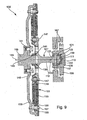
- FIG. 9 shows a longitudinal section of a further device 103 'for coupling two waves with a coupling element 101'.
- the same parts are provided with the same reference numerals, so that in this respect to the description of FIG. 8 is referenced.
- the ball head 141 and the ball socket 143 of the ball joint 139 are formed here only as spherical zones, so as two-sided, parallel truncated spherical surfaces.
- the ball joint 139 thus allows a wobbling movement of the associated intermediate shaft 115 'and a rotation thereof about the intermediate axis 133.
- the ball socket 143 is associated with a swash plate 145.
- the swash plate 145 is by means of suitable fixing means 147th fixed to the intermediate shaft 115 '.
- a spherical bearing 149 is fixed to the swash plate 145 and the intermediate shaft 115 '.
- a vibration damping element 151 which is designed here as a linear spring damper element 151, connected. Spring damper systems, in particular with spiral springs, are known, so that will not be discussed further here.
- the vibration damping element is connected between the spherical bearing 149 and another spherical bearing 155.
- This spherical bearing 155 is connected by means of suitable fixing means 157 to a first rotating mass 159.
- the first rotating mass 159 can be connected via a flange 161 to a shaft with a first axis 163, which is shown in phantom here.
- the shaft is a crankshaft 165 of an internal combustion engine.
- the in FIG. 9 shown state corresponds to the idle state.
- the vibration damping elements 151 are arranged radially to the first axis 162 of the crankshaft 165.
- a wobbling movement causes a deflection of the vibration damping elements 151 relative to the plane of rotation of the crankshaft 65.
- the vibration damping elements counteract the rotation and limit the maximum possible angle of rotation.
- a tumbling motion or a relative rotation causes an extension or shortening of the vibration damping element 151, so that this can absorb or release energy.
- an angled transmission of a rotational movement from the first axis 163 to the intermediate axis 133 of the intermediate shaft 115 ' is possible.
- a torque in particular up to 500 Nm, can be transmitted via the device 103 'with damping of torsional vibrations.
- the coupling element 103 ' can be applied weaker. From the intermediate shaft 115 ', this rotational movement and the torque can be further transmitted to the intermediate piece 135, which is assigned to the ball joint assembly 105.
- the intermediate piece 135 is in particular an output shaft, which is not shown here, and / or a second rotating mass, which is also not shown here assigned.
- the intermediate piece 135 is rotatably supported by means of suitable bearings 167, wherein its axis of rotation can adopt a certain angle and / or axial offset to the first axis 163 within certain limits.
- An axial offset of 4 mm and an angular offset of the intermediate axis 133 to the first axis 163 of 6 ° are preferred.
- FIG. 10 shows a further advantageous device 103 "with a coupling element 101".
- the same parts are provided with the same reference numerals, so that in this respect to the description of FIGS. 8 and 9 is referenced.
- a first shaft 169 and a second shaft 171 can be seen.
- the shafts 169, 171 are coupled via the device 103 "and the coupling element 101".
- the intermediate shaft 115 is associated with two swash plates 145 which lie opposite one another in a mirror image in addition to the first mass 159, a further, mirror-image constructed rotating mass 173 on.
- the entire device 103 "here is characterized by parts constructed in mirror image to one another, but it is also conceivable to have a different design in which the parts lying opposite one another are dimensioned and designed in a mirror-inverted manner FIG. 9 was done, will be discussed here only on the operation.
- the representation according to FIG. 10 shows the arrangement with offset axes of rotation 163, 137 of the shafts 169, 171.
- a torque and / or rotational movement is from the first shaft 169 via the first mass 159, the spherical bearings 155, the vibration damping elements 151, the spherical bearings 149 on the swash plate 145 and From there, the torque and / or rotational movement is transmitted in reverse order to the shaft 171.
- the swash plates 145 lead relative to the masses 159, 173 a complete tumbling movement within a wobble area corresponding to the angle between the first axis 163 and the intermediate axis 133 of the intermediate shaft 115 ".
- the vibration damping elements 151 absorb energy in accordance with their lengthening and shortening and at least partially release them again. If a torque is transmitted in addition to the rotational movement, there is still a deflection of the vibration damping elements 151 with respect to an imaginary diameter line. In this case, the vibration damping elements 151 are additionally lengthened, as a result of which they absorb energy or convert it into friction energy to a desired extent. Thus, the principle of a torsion damping system is realized. It can be seen that the coupling element 101 "is part of this vibration damping system, thus resulting in a particularly compact design of the arrangement.” Depending on the design of the vibration damping elements, more or less energy is converted into friction To optimize compact design and damping of torsional vibrations. In this arrangement too, the coupling element 101 "is arranged between the rotating masses 159 and 173, which results in a small space requirement for the device 103".
- FIGS. 11 to 13 show a coupling element 201, in particular for a device 203 for coupling two shafts, and various sub-assemblies of the device 203rd
- Coupling element 201 shown has an eccentric 205 which is associated with an eccentric pin 207 and a coupling plate 209.
- the coupling element 201 here has a total of six eccentrics 205 with the associated eccentric pins 207, of which, due to the cutting path along the in FIG. 15 drawn line XI-XI only one is visible. It is possible to provide more or fewer eccentric 205 on the coupling plate 209.
- the eccentric 205 is rotatably mounted about an eccentric axis 211 and a pin axis 213, which are each indicated by dash-dotted lines.
- the eccentric bolt 207 is two Assigned discs 215, 215 '.
- the eccentric 205 is inserted into a bore 217 of the coupling plate 209, whose bore axis corresponds to the eccentric axis 213.
- the eccentric 205 is freely rotatably mounted in the bore 217.
- the discs 215, 215 'and the coupling plate 209 are coupled via the eccentric 205 with its eccentric pin 207.
- the coupling element 201 is in particular a first rotating mass 219, which in FIG. 11 and a second rotating mass 221 shown in FIG FIG. 13 is shown assigned.
- the assignment takes place by means of suitable fixing means, in particular by means of a flange. It is also possible, instead of the fixed connection of the rotating masses 219, 221 produced by a flange, to choose for at least one of the masses 219, 221 a connection which permits a relative rotation.
- FIG. 11 is such a connection of the first mass 219 to the discs 215, 215 'shown.
- the first rotating mass 219 is screwed via a flange 223 to a bearing plate 225.
- a bearing area 227 of the disk 215, a bearing shell 231 and a bearing portion 229 of the bearing plate 225 form a friction bearing 232 for the discs 215, 215 'fixedly connected to one another via the eccentric pins about a first axis of rotation 233 which is indicated by dash-dotted lines.
- the first rotating mass 219 is also rotatably mounted about the first axis 233 by means of a bearing, not shown here.
- the coupling of the two disks 215, 215 'and the first masses 219 takes place via a vibration damping element 235, which here comprises an inner bow spring 237, an outer bow spring 239, a friction bearing 241 for the outer bow spring 239 and the friction bearing 232 described above.
- the vibration damping element 235 Since the second rotating mass 221 is coupled via the coupling plate 209 and the eccentric 205 to the two disks 215, 215 ', ultimately the two rotating masses 219, 221 can be rotated relative to one another.
- the vibration damping element 235 according to the angle of rotation, absorbs energy or releases it again or converts part of it into frictional energy.
- device 203 realized the principle of a Torsionsschwingungsdämpfungssystems.
- the rotating masses 219, 221 and the vibration damping element 235 are to be interpreted in the respective application, ie on the expected torsional vibrations. It does not matter which type of bearings 232, 241 are used. Also possible at this point ball bearings, roller bearings, plain bearings or other known bearings.
- FIGS. 11 to 13 It can also be seen that a rotational movement of the first mass 219 about the first axis 233 via the eccentric 205 and the clutch plate 209 is transmitted so that the second rotating mass 221 along a second axis 243, which is shown here in phantom rotated.
- corresponding bearings which are not shown here are provided for the second rotating mass 221.
- the spring stops 251 For transmitting a torque between the vibration damping element 235 and the two disks 215, 215 ', these webs 249, the spring stops 251 form.
- the rotating mass 221 and the coupling plate 209 have a flange 253, over which they are screwed.
- FIG. 13 shown second mass 221 a ring gear 255, via which this, for example by an electric motor or a starter for internal combustion engines, can be driven. Furthermore, a captive, in particular a central bore for introducing a screw can be provided.
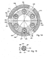
- FIG. 14 shows a schematic cross section of the in the FIGS. 11 and 12
- the same parts are provided with the same reference numerals, so far as the description of the FIGS. 11 and 12 is referenced.
- FIG. 15 shows an eccentric 205 of the coupling element 201.
- the same parts are provided with the same reference numerals, so that reference is made to the description of the preceding figures.
- the eccentric 205 and the eccentric pin 207 are surrounded by bearing areas 261.
- the bearing areas 261 can be interpreted from a tribological point of view so that minimal wear and minimal friction occurs to maximize the life and efficiency of the To achieve coupling element 201. It is also advantageous that the eccentric 205 is coupled via the vibration damping element 235 with the crankshaft 263, which also minimizes friction and wear.
- the bearing portions 261 are formed as a friction bearing. Conceivable, however, are other advantageous bearing principles, such as ball bearings, rolling bearings or the like.
- FIG. 16 shows the in the FIGS. 11 to 13 shown device 203 in the mounted state.
- the same parts are provided with the same reference numerals, so that reference is made to the description of the preceding figures.
- the discs 215, 215 ' are assigned via the flange 223 of a crankshaft 263 of an internal combustion engine.
- the axis of rotation of the crankshaft 263 thus corresponds to the first axis 233.
- the crankshaft 263 is mounted eccentrically relative to an engine block 267 of the internal combustion engine. This eccentric movement, which also displaces the first axis 233, can be utilized to change the compression of the internal combustion engine.
- FIG. 14 is indicated by a half circle 269 caused by the Exzenter Swiss 265 trajectory of the first axis 233 of the crankshaft 263.
- eccentric 265 caused eccentricity of the first axis 233 of the crankshaft 263 corresponds exactly to the offset of the axes 233 and 243. Since the inner discs 215, 215 'and the first mass 219 are flanged to the crankshaft, they are adjusted with an adjustment of the crankshaft ,
- the second mass 221 is connected by the flange 253 fixed to the clutch plate 209 and rotatably supported by a suitable bearings 271 together with this relative to a housing 273 of the device 203.
- the housing 273 in turn is fixedly connected to the engine block 267. Since the eccentricity of the crankshaft 263, which is caused by the Exzenter Swiss 265, exactly corresponds to the axial offset of the axes 233 and 243, is guided by an adjustment of the crankshaft 263 whose axis 233 at a constant distance about the second axis 243 of the second mass 221. However, this axial offset is offset by the arrangement of the discs 215, 215 ', the eccentric 205 and the clutch plate 209. It is thus possible, despite an adjustment of the crankshaft axis 233 of the second mass 221, to assign a fixed shaft, for example an output shaft, in particular a transmission input shaft.
- the coupling element 201 is completely integrated into the device 203, which compensates for the axial offset between the crankshaft 263 and the output shaft.
- the space of the device 203 is particularly small. Since the transmission of the torque over the axial offset causes no radial bearing forces, the bearing losses are particularly low.
- the device 203 provides an optimum compromise in terms of efficiency, compactness, and damping of torsional vibrations.
- FIG. 17 shows the bolt circle of the flange 253 of FIG. 16
- the same parts are provided with the same reference numerals, so that reference is made to the description of the preceding figures.
- the bolt circle of the flange 253 is offset relative to its axis of rotation, that is to say the first axis 233 or the crankshaft axis 233.
- the offset is indicated by the two lines 257 and corresponds exactly to the axial offset of the axes 233, 243.
- the bolt circle of the flange is thus arranged eccentrically to the first axis 233 and centric to the second axis 243. This is advantageous in the assembly of the device 203, with reference to FIGS FIG. 16 shortly received:
- the screw connection of the flange 253 of the crankshaft 263 and the first mass 219 is produced by means of an assembly aid 275 which can be introduced into a bore 277 of the flange 253 for this purpose.
- the flange 253 also has a bolt circle having the same diameter of the bolt circle of the flange 223 and is arranged centrally to the axis 243 of the second mass 221. The bolt holes of the flanges 223 and 253 can therefore be brought exactly to coincide, so that the mounting aid 275 in the bore 277 of the flange 253 for tightening the flange 223 is inserted.
- the screws of the flange 253 can be tightened in a second step.
- FIG. 18 shows the device 203 with the coupling element 201 in combination with the direction indicated by the partially shown engine block 267 internal combustion engine and a dry clutch 279.
- the same parts are provided with the same reference numerals, so that reference is made to the description of the preceding figures.
- the dry clutch 279 is assigned by means of suitable connecting means 281, the second rotating mass 221, which is in particular a cast plate. Depending on the operating position of the same, a rigid connection to an output shaft 283, in particular a transmission input shaft, can be produced via the clutch 279.
- the axis of rotation of the output shaft 283 corresponds to the second axis 243, ie the axis of rotation of the second rotating mass 221.
- the adjustable crankshaft 263 and the output shaft 283 are coupled via the device 203 to the coupling element 201 despite the axial offset of the axes 233, 243, that in the smallest space, under damping of torsional vibrations with good efficiency, a torque or a rotational movement can be transmitted.
- the device 203 has an oil lubrication.
- oil passages 285 are provided in the various components, which are partially shown in dashed lines.
- various oil lakes 287 are provided for guiding the oil, which are indicated by horizontal lines.
- the oil lakes 287 are formed due to the centrifugal forces acting on the oil, which is entrained by the rotating parts of the device 203.
Landscapes
- Engineering & Computer Science (AREA)
- General Engineering & Computer Science (AREA)
- Mechanical Engineering (AREA)
- Physics & Mathematics (AREA)
- Acoustics & Sound (AREA)
- Aviation & Aerospace Engineering (AREA)
- Mechanical Operated Clutches (AREA)
Claims (14)
- Dispositif pour accoupler deux arbres disposés à distance l'un de l'autre avec leurs axes parallèles ou inclinés l'un par rapport à l'autre, comprenant au moins un élément d'accouplement (3), au moins une première masse rotative (43) et une deuxième masse rotative (55) étant prévues, lesquelles sont accouplées en rotation pour l'amortissement d'oscillations de torsion par le biais d'au moins un amortisseur d'oscillations (29), un vilebrequin (41) associé à la première masse rotative (43) et un arbre de prise de force (59) associé à la deuxième masse rotative (55) présentant un décalage axial, l'amortisseur d'oscillations (29) présentant des éléments élastiques (31) réalisés sous forme de ressorts de compression, lesquels peuvent être serrés entre des butées connectées de manière rotative aux masses (43, 55) pouvant tourner l'une par rapport à l'autre, des éléments qui permettent une compensation du décalage axial agissant en série avec les éléments élastiques (31).
- Dispositif selon la revendication 1, caractérisé en ce que les éléments de compensation du décalage axial comprennent au moins un élément élastique (27).
- Dispositif selon la revendication 2, caractérisé en ce que l'au moins un élément élastique (27) est réalisé sous forme de ressort de compression.
- Dispositif selon l'une quelconque des revendications 2 ou 3, caractérisé en ce que l'au moins un élément élastique (27) est précontraint.
- Dispositif selon l'une quelconque des revendications 2 à 4, caractérisé par quatre disques (5, 21) disposés parallèlement les uns aux autres, accouplés par le biais de l'au moins un élément élastique, deux d'entre eux étant à chaque fois connectés fixement l'un à l'autre.
- Dispositif selon la revendication 5, caractérisé en ce que les disques (5, 21) présentent à chaque fois au moins un orifice (7) qui est réalisé de préférence sous forme oblongue et qui s'étend sous forme courbe dans la direction périphérique des disques.
- Dispositif selon la revendication 6, caractérisé en ce que deux éléments élastiques (27) sont associés à l'au moins un orifice (7).
- Dispositif selon l'une quelconque des revendications 2 à 7, caractérisé en ce que deux disques internes (5) et deux disques externes (21), lesquels sont respectivement associés l'un à l'autre, sont prévus.
- Dispositif selon la revendication 8, caractérisé en ce que les disques (5, 21) connectés à chaque fois les uns aux autres sont réalisés et disposés de manière essentiellement symétrique par rapport à un axe médian théorique.
- Dispositif selon l'une quelconque des revendications 8 ou 9, caractérisé en ce que l'au moins un orifice (7) des deux disques internes (5) est disposé de manière tournée par rapport à l'au moins un orifice (7) des deux disques externes (21).
- Dispositif selon l'une quelconque des revendications 8 à 10, caractérisé en ce que l'au moins un élément élastique (27) coopère avec un palier formé par les disques internes (5), en particulier avec un canal de ressort et une butée de ressort, et avec un palier formé par les disques externes (21), en particulier un canal de ressort et une butée de ressort.
- Dispositif selon l'une quelconque des revendications 8 à 11, caractérisé en ce que les disques internes (5) et les disques externes (21) sont accouplés élastiquement de telle sorte qu'ils puissent être décalés axialement les uns par rapport aux autres et qu'un couple puisse être transmis des disques internes (5) aux disques externes (21)- ou inversement - dans l'état décalé, avec les axes parallèles ou coaxiaux.
- Dispositif, en particulier selon l'une quelconque des revendications 8 à 12, caractérisé en ce que les disques internes (5) et les disques externes (21) présentent à chaque fois une région (17), en particulier une nervure et/ou une bride pour le transfert d'un couple à un autre composant.
- Dispositif selon la revendication 1, caractérisé en ce que les éléments de compensation du décalage axial comprennent au moins un excentrique ajustable (205).
Applications Claiming Priority (3)
| Application Number | Priority Date | Filing Date | Title |
|---|---|---|---|
| DE10252965 | 2002-11-14 | ||
| DE10252965 | 2002-11-14 | ||
| PCT/DE2003/003701 WO2004044451A1 (fr) | 2002-11-14 | 2003-11-08 | Dispositif pour accoupler deux arbres |
Publications (2)
| Publication Number | Publication Date |
|---|---|
| EP1563203A1 EP1563203A1 (fr) | 2005-08-17 |
| EP1563203B1 true EP1563203B1 (fr) | 2014-04-30 |
Family
ID=32308538
Family Applications (1)
| Application Number | Title | Priority Date | Filing Date |
|---|---|---|---|
| EP03776834.8A Expired - Lifetime EP1563203B1 (fr) | 2002-11-14 | 2003-11-08 | Dispositif pour accoupler deux arbres |
Country Status (7)
| Country | Link |
|---|---|
| EP (1) | EP1563203B1 (fr) |
| JP (1) | JP4826937B2 (fr) |
| KR (3) | KR101181950B1 (fr) |
| CN (1) | CN100482968C (fr) |
| AU (1) | AU2003286117A1 (fr) |
| DE (1) | DE10393579D2 (fr) |
| WO (1) | WO2004044451A1 (fr) |
Families Citing this family (19)
| Publication number | Priority date | Publication date | Assignee | Title |
|---|---|---|---|---|
| EP1635080A3 (fr) * | 2004-09-10 | 2007-06-20 | LuK Lamellen und Kupplungsbau Beteiligungs KG | Dispositif pour coupler deux arbres à déport axial |
| FR2919696B1 (fr) * | 2007-08-02 | 2010-03-12 | Valeo Embrayages | Dispositif d'accouplement apte a transmettre un couple entre un organe menant et un organe mene |
| DE112007003715A5 (de) * | 2007-12-31 | 2010-11-18 | Fev Motorentechnik Gmbh | Parallelkurbelgetriebe |
| DE102008053632B3 (de) * | 2008-10-29 | 2009-12-24 | Geislinger Gmbh | Drehschwingungsdämpfer und drehendes Bauteil mit Drehschwingungsdämpfer |
| KR101050103B1 (ko) * | 2009-03-27 | 2011-07-19 | 주식회사 서진클러치 | 듀얼 메스 플라이휠 |
| KR101449526B1 (ko) | 2010-12-17 | 2014-10-13 | 현대중공업 주식회사 | 개방형 코일 스프링 비틀림 진동 댐퍼 |
| KR101449530B1 (ko) | 2010-12-17 | 2014-10-13 | 현대중공업 주식회사 | 폐쇄형 코일 스프링 비틀림 진동 댐퍼 |
| DE102010055341A1 (de) | 2010-12-21 | 2012-06-21 | Fev Motorentechnik Gmbh | Exzentrische Kurbelwellenlagerung mit Zweimassenschwungrad |
| DE102011107245A1 (de) * | 2011-07-13 | 2012-03-01 | Daimler Ag | Formschlusskupplungsbetätigungsvorrichtung eines Kraftfahrzeuggetriebes |
| DE102012002660B4 (de) * | 2012-02-10 | 2022-11-17 | Süddeutsche Gelenkscheibenfabrik GmbH & Co. KG | Elastische Doppel-Torsionskupplung |
| BR102014005920A2 (pt) * | 2013-03-15 | 2015-11-24 | Dana Heavy Vehicle Sys Group | dispositivos de cancelamento de pico de torque para um motor de combustão interna e dispositivo de compensação de ondulação de torque |
| DE102013214352A1 (de) * | 2013-07-23 | 2015-01-29 | Zf Friedrichshafen Ag | Drehschwingungsdämpfungsanordnung für den Antriebsstrang eines Kraftfahrzeugs |
| CN105518338B (zh) * | 2013-09-04 | 2019-04-09 | 舍弗勒技术股份两合公司 | 离心力摆止挡弹簧元件,离心力摆装置以及部件组件 |
| CN104653702B (zh) * | 2013-11-25 | 2017-10-31 | 上海汽车集团股份有限公司 | 双质量飞轮 |
| US9500259B1 (en) * | 2015-08-11 | 2016-11-22 | Gm Global Technology Operations, Llc | High performance torsional vibration isolator |
| FR3075293B1 (fr) * | 2017-12-20 | 2019-11-22 | Valeo Embrayages | Amortisseur de torsion, voile et ensemble associes |
| DE102018106287A1 (de) * | 2018-03-19 | 2019-09-19 | Schaeffler Technologies AG & Co. KG | Hybridmodul mit zweigeteiltem Sekundär-Drehschwingungsdämpfer |
| CN113557370B (zh) * | 2019-07-01 | 2023-07-18 | 舍弗勒技术股份两合公司 | 离合器从动盘及离合器 |
| DE102020114017A1 (de) | 2020-05-26 | 2021-12-02 | Schaeffler Technologies AG & Co. KG | Ausgleichskupplung |
Family Cites Families (12)
| Publication number | Priority date | Publication date | Assignee | Title |
|---|---|---|---|---|
| CH424392A (de) * | 1965-05-25 | 1966-11-15 | C Schachenmann & Co Dr | Vorrichtung zum Kuppeln zweier gegenseitig parallel verstellbarer Wellen |
| FR2276623A1 (fr) | 1974-06-28 | 1976-01-23 | Int Vibration Engineer | Dispositif hydraulique de maintien d'alignement d'elements mobiles |
| AT352485B (de) * | 1974-06-29 | 1979-09-25 | Chivari Ilie | Kupplung zum kuppeln achsversetzter umlaufender wellen |
| JPS5712272Y2 (fr) * | 1977-10-24 | 1982-03-11 | ||
| US4208889A (en) * | 1978-08-30 | 1980-06-24 | Barry Wright Corporation | Constant velocity, torsionally rigid, flexible coupling |
| US4331003A (en) | 1979-07-26 | 1982-05-25 | Barry Wright Corporation | Flexible coupling |
| JPH079252B2 (ja) * | 1986-09-30 | 1995-02-01 | アイシン精機株式会社 | トルク変動吸収装置 |
| US5536208A (en) * | 1987-05-21 | 1996-07-16 | Luk Lamellen Und Kupplungsbau Gmbh | Apparatus for damping vibrations in power trains of motor vehicles |
| IN189877B (fr) * | 1997-08-04 | 2003-05-03 | Luk Lamellen & Kupplungsbau | |
| DE50001035D1 (de) * | 1999-03-24 | 2003-02-13 | Fev Motorentech Gmbh | Kupplungselement zur verbindung von zwei gleichachsig hintereinander und mit querabstand zueinander angeordneten achsparallelen wellen |
| JP4605907B2 (ja) * | 1999-03-24 | 2011-01-05 | エフ・エー・フアウ・モトーレンテヒニック・ゲゼルシヤフト・ミト・ベシユレンクテル・ハフツング | 前後で同軸にかつ互いに横方向間隔をおいて配置された軸線平行な2本の軸を連結する連結要素 |
| FR2835298B1 (fr) * | 2002-01-25 | 2004-04-16 | Peugeot Citroen Automobiles Sa | Dispositif d'accouplement elastique entre le rotor d'une machine electrique tournante reversible et l'arbre primaire de la boite de vitesses d'un moteur thermique de vehicule automobile |
-
2003
- 2003-11-08 KR KR1020117020438A patent/KR101181950B1/ko not_active IP Right Cessation
- 2003-11-08 KR KR1020117020439A patent/KR101173002B1/ko not_active IP Right Cessation
- 2003-11-08 KR KR1020057008604A patent/KR101136583B1/ko not_active IP Right Cessation
- 2003-11-08 JP JP2004550642A patent/JP4826937B2/ja not_active Expired - Fee Related
- 2003-11-08 EP EP03776834.8A patent/EP1563203B1/fr not_active Expired - Lifetime
- 2003-11-08 WO PCT/DE2003/003701 patent/WO2004044451A1/fr active Application Filing
- 2003-11-08 AU AU2003286117A patent/AU2003286117A1/en not_active Abandoned
- 2003-11-08 DE DE10393579T patent/DE10393579D2/de not_active Expired - Fee Related
- 2003-11-08 CN CNB2003801034081A patent/CN100482968C/zh not_active Expired - Fee Related
Also Published As
| Publication number | Publication date |
|---|---|
| DE10393579D2 (de) | 2005-07-07 |
| KR101136583B1 (ko) | 2012-04-18 |
| JP2006506583A (ja) | 2006-02-23 |
| AU2003286117A1 (en) | 2004-06-03 |
| KR101181950B1 (ko) | 2012-09-12 |
| WO2004044451A1 (fr) | 2004-05-27 |
| CN1711432A (zh) | 2005-12-21 |
| KR20050074618A (ko) | 2005-07-18 |
| KR20110101258A (ko) | 2011-09-15 |
| KR20110103476A (ko) | 2011-09-20 |
| KR101173002B1 (ko) | 2012-09-04 |
| EP1563203A1 (fr) | 2005-08-17 |
| JP4826937B2 (ja) | 2011-11-30 |
| CN100482968C (zh) | 2009-04-29 |
Similar Documents
| Publication | Publication Date | Title |
|---|---|---|
| EP1563203B1 (fr) | Dispositif pour accoupler deux arbres | |
| EP0304474B1 (fr) | Accouplement elastique | |
| EP1106853B1 (fr) | Embrayage avec amortisseur de torsion | |
| DE102009037481B4 (de) | Drehzahladaptiver Tilger, insbesondere Fliehkraftpendeleinrichtung | |
| WO2007045418A1 (fr) | Dispositif d'accouplement servant a transmettre un couple de rotation | |
| DE19834729A1 (de) | Einrichtung zum Dämpfen von Drehschwingungen | |
| WO2010043193A1 (fr) | Agencement d'arbre de commande pour une transmission d'un véhicule à moteur | |
| DE102007057431B4 (de) | Hydrodynamische Kopplungseinrichtung | |
| DE8535705U1 (de) | Einrichtung zum Kompensieren von Drehstößen | |
| EP2909502A1 (fr) | Système d'amortissement des vibrations de torsion à précontrainte | |
| DE3049670T1 (de) | Zweistufiger koaxialer federdaempfer | |
| EP2347145A1 (fr) | Amortisseur de vibrations torsionnelles pour la chaîne cinématique d'un véhicule | |
| EP1462675B1 (fr) | Amortisseur de vibrations de torsion | |
| DE19818047A1 (de) | Antriebswelle | |
| EP2769117B1 (fr) | Dispositif d'amortissement de vibrations de rotation, en particulier pour la chaîne cinématique d'un véhicule | |
| DE10052786B4 (de) | Torsionsdämpfungsmechanismus mit Zusatzmasse | |
| DE10018955B4 (de) | Antriebssystem | |
| EP1584838B1 (fr) | Amortisseur de vibrations de torsion | |
| EP1496288B1 (fr) | Amortisseur de vibrations torsionelles | |
| EP2598774A1 (fr) | Amortisseur d'oscillations de torsion | |
| DE19808730C2 (de) | Drehschwingungsdämpfer | |
| WO2014026809A1 (fr) | Ensemble amortisseur de vibrations de torsion à dérivation de puissance | |
| DE10066436B4 (de) | Schwingungsdämpfersystem | |
| EP1496289A1 (fr) | Amortisseur de vibrations de torsion et bloc de friction pour un amortisseur de vibrations de torsion | |
| DE102005041946A1 (de) | Vorrichtung zur Kopplung zweier Wellen mit axialem Versatz |
Legal Events
| Date | Code | Title | Description |
|---|---|---|---|
| PUAI | Public reference made under article 153(3) epc to a published international application that has entered the european phase |
Free format text: ORIGINAL CODE: 0009012 |
|
| 17P | Request for examination filed |
Effective date: 20050614 |
|
| AK | Designated contracting states |
Kind code of ref document: A1 Designated state(s): AT BE BG CH CY CZ DE DK EE ES FI FR GB GR HU IE IT LI LU MC NL PT RO SE SI SK TR |
|
| AX | Request for extension of the european patent |
Extension state: AL LT LV MK |
|
| DAX | Request for extension of the european patent (deleted) | ||
| 17Q | First examination report despatched |
Effective date: 20071109 |
|
| RAP1 | Party data changed (applicant data changed or rights of an application transferred) |
Owner name: SCHAEFFLER TECHNOLOGIES GMBH & CO. KG |
|
| RAP1 | Party data changed (applicant data changed or rights of an application transferred) |
Owner name: SCHAEFFLER TECHNOLOGIES AG & CO. KG |
|
| GRAP | Despatch of communication of intention to grant a patent |
Free format text: ORIGINAL CODE: EPIDOSNIGR1 |
|
| INTG | Intention to grant announced |
Effective date: 20131115 |
|
| RAP1 | Party data changed (applicant data changed or rights of an application transferred) |
Owner name: SCHAEFFLER TECHNOLOGIES GMBH & CO. KG |
|
| GRAS | Grant fee paid |
Free format text: ORIGINAL CODE: EPIDOSNIGR3 |
|
| GRAA | (expected) grant |
Free format text: ORIGINAL CODE: 0009210 |
|
| STAA | Information on the status of an ep patent application or granted ep patent |
Free format text: STATUS: THE PATENT HAS BEEN GRANTED |
|
| AK | Designated contracting states |
Kind code of ref document: B1 Designated state(s): AT BE BG CH CY CZ DE DK EE ES FI FR GB GR HU IE IT LI LU MC NL PT RO SE SI SK TR |
|
| REG | Reference to a national code |
Ref country code: CH Ref legal event code: EP Ref country code: GB Ref legal event code: FG4D Free format text: NOT ENGLISH |
|
| REG | Reference to a national code |
Ref country code: AT Ref legal event code: REF Ref document number: 665355 Country of ref document: AT Kind code of ref document: T Effective date: 20140515 |
|
| REG | Reference to a national code |
Ref country code: IE Ref legal event code: FG4D Free format text: LANGUAGE OF EP DOCUMENT: GERMAN |
|
| REG | Reference to a national code |
Ref country code: DE Ref legal event code: R096 Ref document number: 50315037 Country of ref document: DE Effective date: 20140612 |
|
| REG | Reference to a national code |
Ref country code: NL Ref legal event code: VDEP Effective date: 20140430 |
|
| PG25 | Lapsed in a contracting state [announced via postgrant information from national office to epo] |
Ref country code: NL Free format text: LAPSE BECAUSE OF FAILURE TO SUBMIT A TRANSLATION OF THE DESCRIPTION OR TO PAY THE FEE WITHIN THE PRESCRIBED TIME-LIMIT Effective date: 20140430 Ref country code: GR Free format text: LAPSE BECAUSE OF FAILURE TO SUBMIT A TRANSLATION OF THE DESCRIPTION OR TO PAY THE FEE WITHIN THE PRESCRIBED TIME-LIMIT Effective date: 20140731 Ref country code: BG Free format text: LAPSE BECAUSE OF FAILURE TO SUBMIT A TRANSLATION OF THE DESCRIPTION OR TO PAY THE FEE WITHIN THE PRESCRIBED TIME-LIMIT Effective date: 20140730 Ref country code: FI Free format text: LAPSE BECAUSE OF FAILURE TO SUBMIT A TRANSLATION OF THE DESCRIPTION OR TO PAY THE FEE WITHIN THE PRESCRIBED TIME-LIMIT Effective date: 20140430 Ref country code: CY Free format text: LAPSE BECAUSE OF FAILURE TO SUBMIT A TRANSLATION OF THE DESCRIPTION OR TO PAY THE FEE WITHIN THE PRESCRIBED TIME-LIMIT Effective date: 20140430 |
|
| PG25 | Lapsed in a contracting state [announced via postgrant information from national office to epo] |
Ref country code: ES Free format text: LAPSE BECAUSE OF FAILURE TO SUBMIT A TRANSLATION OF THE DESCRIPTION OR TO PAY THE FEE WITHIN THE PRESCRIBED TIME-LIMIT Effective date: 20140430 Ref country code: SE Free format text: LAPSE BECAUSE OF FAILURE TO SUBMIT A TRANSLATION OF THE DESCRIPTION OR TO PAY THE FEE WITHIN THE PRESCRIBED TIME-LIMIT Effective date: 20140430 |
|
| PG25 | Lapsed in a contracting state [announced via postgrant information from national office to epo] |
Ref country code: PT Free format text: LAPSE BECAUSE OF FAILURE TO SUBMIT A TRANSLATION OF THE DESCRIPTION OR TO PAY THE FEE WITHIN THE PRESCRIBED TIME-LIMIT Effective date: 20140901 |
|
| PG25 | Lapsed in a contracting state [announced via postgrant information from national office to epo] |
Ref country code: RO Free format text: LAPSE BECAUSE OF FAILURE TO SUBMIT A TRANSLATION OF THE DESCRIPTION OR TO PAY THE FEE WITHIN THE PRESCRIBED TIME-LIMIT Effective date: 20140430 Ref country code: CZ Free format text: LAPSE BECAUSE OF FAILURE TO SUBMIT A TRANSLATION OF THE DESCRIPTION OR TO PAY THE FEE WITHIN THE PRESCRIBED TIME-LIMIT Effective date: 20140430 Ref country code: DK Free format text: LAPSE BECAUSE OF FAILURE TO SUBMIT A TRANSLATION OF THE DESCRIPTION OR TO PAY THE FEE WITHIN THE PRESCRIBED TIME-LIMIT Effective date: 20140430 Ref country code: EE Free format text: LAPSE BECAUSE OF FAILURE TO SUBMIT A TRANSLATION OF THE DESCRIPTION OR TO PAY THE FEE WITHIN THE PRESCRIBED TIME-LIMIT Effective date: 20140430 Ref country code: SK Free format text: LAPSE BECAUSE OF FAILURE TO SUBMIT A TRANSLATION OF THE DESCRIPTION OR TO PAY THE FEE WITHIN THE PRESCRIBED TIME-LIMIT Effective date: 20140430 |
|
| REG | Reference to a national code |
Ref country code: DE Ref legal event code: R026 Ref document number: 50315037 Country of ref document: DE |
|
| PLBI | Opposition filed |
Free format text: ORIGINAL CODE: 0009260 |
|
| RAP2 | Party data changed (patent owner data changed or rights of a patent transferred) |
Owner name: SCHAEFFLER TECHNOLOGIES AG & CO. KG |
|
| PLAX | Notice of opposition and request to file observation + time limit sent |
Free format text: ORIGINAL CODE: EPIDOSNOBS2 |
|
| 26 | Opposition filed |
Opponent name: ZF FRIEDRICHSHAFEN AG Effective date: 20150130 |
|
| REG | Reference to a national code |
Ref country code: DE Ref legal event code: R081 Ref document number: 50315037 Country of ref document: DE Owner name: SCHAEFFLER TECHNOLOGIES AG & CO. KG, DE Free format text: FORMER OWNER: LUK LAMELLEN UND KUPPLUNGSBAU BETEILIGUNGS KG, 77815 BUEHL, DE Effective date: 20140430 Ref country code: DE Ref legal event code: R081 Ref document number: 50315037 Country of ref document: DE Owner name: SCHAEFFLER TECHNOLOGIES AG & CO. KG, DE Free format text: FORMER OWNER: SCHAEFFLER TECHNOLOGIES GMBH & CO. KG, 91074 HERZOGENAURACH, DE Effective date: 20150213 |
|
| PG25 | Lapsed in a contracting state [announced via postgrant information from national office to epo] |
Ref country code: IT Free format text: LAPSE BECAUSE OF FAILURE TO SUBMIT A TRANSLATION OF THE DESCRIPTION OR TO PAY THE FEE WITHIN THE PRESCRIBED TIME-LIMIT Effective date: 20140430 |
|
| REG | Reference to a national code |
Ref country code: DE Ref legal event code: R026 Ref document number: 50315037 Country of ref document: DE Effective date: 20150130 |
|
| PG25 | Lapsed in a contracting state [announced via postgrant information from national office to epo] |
Ref country code: LU Free format text: LAPSE BECAUSE OF FAILURE TO SUBMIT A TRANSLATION OF THE DESCRIPTION OR TO PAY THE FEE WITHIN THE PRESCRIBED TIME-LIMIT Effective date: 20141108 Ref country code: MC Free format text: LAPSE BECAUSE OF FAILURE TO SUBMIT A TRANSLATION OF THE DESCRIPTION OR TO PAY THE FEE WITHIN THE PRESCRIBED TIME-LIMIT Effective date: 20140430 Ref country code: BE Free format text: LAPSE BECAUSE OF NON-PAYMENT OF DUE FEES Effective date: 20141130 |
|
| REG | Reference to a national code |
Ref country code: CH Ref legal event code: PL |
|
| GBPC | Gb: european patent ceased through non-payment of renewal fee |
Effective date: 20141108 |
|
| PG25 | Lapsed in a contracting state [announced via postgrant information from national office to epo] |
Ref country code: CH Free format text: LAPSE BECAUSE OF NON-PAYMENT OF DUE FEES Effective date: 20141130 Ref country code: LI Free format text: LAPSE BECAUSE OF NON-PAYMENT OF DUE FEES Effective date: 20141130 Ref country code: SI Free format text: LAPSE BECAUSE OF FAILURE TO SUBMIT A TRANSLATION OF THE DESCRIPTION OR TO PAY THE FEE WITHIN THE PRESCRIBED TIME-LIMIT Effective date: 20140430 |
|
| PLAF | Information modified related to communication of a notice of opposition and request to file observations + time limit |
Free format text: ORIGINAL CODE: EPIDOSCOBS2 |
|
| REG | Reference to a national code |
Ref country code: IE Ref legal event code: MM4A |
|
| PLBB | Reply of patent proprietor to notice(s) of opposition received |
Free format text: ORIGINAL CODE: EPIDOSNOBS3 |
|
| PG25 | Lapsed in a contracting state [announced via postgrant information from national office to epo] |
Ref country code: GB Free format text: LAPSE BECAUSE OF NON-PAYMENT OF DUE FEES Effective date: 20141108 Ref country code: IE Free format text: LAPSE BECAUSE OF NON-PAYMENT OF DUE FEES Effective date: 20141108 |
|
| REG | Reference to a national code |
Ref country code: FR Ref legal event code: PLFP Year of fee payment: 13 |
|
| REG | Reference to a national code |
Ref country code: AT Ref legal event code: MM01 Ref document number: 665355 Country of ref document: AT Kind code of ref document: T Effective date: 20141108 |
|
| PG25 | Lapsed in a contracting state [announced via postgrant information from national office to epo] |
Ref country code: AT Free format text: LAPSE BECAUSE OF NON-PAYMENT OF DUE FEES Effective date: 20141108 |
|
| PG25 | Lapsed in a contracting state [announced via postgrant information from national office to epo] |
Ref country code: HU Free format text: LAPSE BECAUSE OF FAILURE TO SUBMIT A TRANSLATION OF THE DESCRIPTION OR TO PAY THE FEE WITHIN THE PRESCRIBED TIME-LIMIT; INVALID AB INITIO Effective date: 20031108 Ref country code: TR Free format text: LAPSE BECAUSE OF FAILURE TO SUBMIT A TRANSLATION OF THE DESCRIPTION OR TO PAY THE FEE WITHIN THE PRESCRIBED TIME-LIMIT Effective date: 20140430 |
|
| REG | Reference to a national code |
Ref country code: FR Ref legal event code: PLFP Year of fee payment: 14 |
|
| RDAF | Communication despatched that patent is revoked |
Free format text: ORIGINAL CODE: EPIDOSNREV1 |
|
| STAA | Information on the status of an ep patent application or granted ep patent |
Free format text: STATUS: THE PATENT HAS BEEN GRANTED |
|
| APBM | Appeal reference recorded |
Free format text: ORIGINAL CODE: EPIDOSNREFNO |
|
| APBP | Date of receipt of notice of appeal recorded |
Free format text: ORIGINAL CODE: EPIDOSNNOA2O |
|
| APAH | Appeal reference modified |
Free format text: ORIGINAL CODE: EPIDOSCREFNO |
|
| APBQ | Date of receipt of statement of grounds of appeal recorded |
Free format text: ORIGINAL CODE: EPIDOSNNOA3O |
|
| REG | Reference to a national code |
Ref country code: FR Ref legal event code: PLFP Year of fee payment: 15 |
|
| PGFP | Annual fee paid to national office [announced via postgrant information from national office to epo] |
Ref country code: FR Payment date: 20171129 Year of fee payment: 15 |
|
| PGFP | Annual fee paid to national office [announced via postgrant information from national office to epo] |
Ref country code: DE Payment date: 20180131 Year of fee payment: 15 |
|
| REG | Reference to a national code |
Ref country code: DE Ref legal event code: R119 Ref document number: 50315037 Country of ref document: DE |
|
| PG25 | Lapsed in a contracting state [announced via postgrant information from national office to epo] |
Ref country code: DE Free format text: LAPSE BECAUSE OF NON-PAYMENT OF DUE FEES Effective date: 20190601 Ref country code: FR Free format text: LAPSE BECAUSE OF NON-PAYMENT OF DUE FEES Effective date: 20181130 |
|
| APBU | Appeal procedure closed |
Free format text: ORIGINAL CODE: EPIDOSNNOA9O |
|
| PLAB | Opposition data, opponent's data or that of the opponent's representative modified |
Free format text: ORIGINAL CODE: 0009299OPPO |
|
| R26 | Opposition filed (corrected) |
Opponent name: ZF FRIEDRICHSHAFEN AG Effective date: 20150130 |
|
| PLBD | Termination of opposition procedure: decision despatched |
Free format text: ORIGINAL CODE: EPIDOSNOPC1 |
|
| REG | Reference to a national code |
Ref country code: DE Ref legal event code: R100 Ref document number: 50315037 Country of ref document: DE |
|
| PLBM | Termination of opposition procedure: date of legal effect published |
Free format text: ORIGINAL CODE: 0009276 |
|
| 27C | Opposition proceedings terminated |
Effective date: 20220917 |
|
| P01 | Opt-out of the competence of the unified patent court (upc) registered |
Effective date: 20230523 |