EP1563198B1 - Systeme a double embrayage - Google Patents
Systeme a double embrayage Download PDFInfo
- Publication number
- EP1563198B1 EP1563198B1 EP03775366A EP03775366A EP1563198B1 EP 1563198 B1 EP1563198 B1 EP 1563198B1 EP 03775366 A EP03775366 A EP 03775366A EP 03775366 A EP03775366 A EP 03775366A EP 1563198 B1 EP1563198 B1 EP 1563198B1
- Authority
- EP
- European Patent Office
- Prior art keywords
- dual clutch
- secondary side
- vibration damper
- torsional vibration
- primary side
- Prior art date
- Legal status (The legal status is an assumption and is not a legal conclusion. Google has not performed a legal analysis and makes no representation as to the accuracy of the status listed.)
- Expired - Lifetime
Links
- 230000009977 dual effect Effects 0.000 claims abstract description 41
- 230000005540 biological transmission Effects 0.000 claims description 18
- 230000033001 locomotion Effects 0.000 claims description 15
- 230000000712 assembly Effects 0.000 claims description 5
- 238000000429 assembly Methods 0.000 claims description 5
- 230000008878 coupling Effects 0.000 description 31
- 238000010168 coupling process Methods 0.000 description 31
- 238000005859 coupling reaction Methods 0.000 description 31
- 239000013536 elastomeric material Substances 0.000 description 7
- 230000007246 mechanism Effects 0.000 description 6
- 238000010276 construction Methods 0.000 description 5
- 230000015572 biosynthetic process Effects 0.000 description 2
- 230000006835 compression Effects 0.000 description 2
- 238000007906 compression Methods 0.000 description 2
- 238000005755 formation reaction Methods 0.000 description 2
- 239000002184 metal Substances 0.000 description 2
- 230000002093 peripheral effect Effects 0.000 description 2
- 238000002485 combustion reaction Methods 0.000 description 1
- 230000003111 delayed effect Effects 0.000 description 1
- 238000006073 displacement reaction Methods 0.000 description 1
- 239000013013 elastic material Substances 0.000 description 1
- 239000000463 material Substances 0.000 description 1
- 238000000034 method Methods 0.000 description 1
- 230000004048 modification Effects 0.000 description 1
- 238000012986 modification Methods 0.000 description 1
- 229920003052 natural elastomer Polymers 0.000 description 1
- 229920001194 natural rubber Polymers 0.000 description 1
- 239000007787 solid Substances 0.000 description 1
- 229920003051 synthetic elastomer Polymers 0.000 description 1
- 239000005061 synthetic rubber Substances 0.000 description 1
- 238000003466 welding Methods 0.000 description 1
Images


Classifications
-
- F—MECHANICAL ENGINEERING; LIGHTING; HEATING; WEAPONS; BLASTING
- F16—ENGINEERING ELEMENTS AND UNITS; GENERAL MEASURES FOR PRODUCING AND MAINTAINING EFFECTIVE FUNCTIONING OF MACHINES OR INSTALLATIONS; THERMAL INSULATION IN GENERAL
- F16D—COUPLINGS FOR TRANSMITTING ROTATION; CLUTCHES; BRAKES
- F16D21/00—Systems comprising a plurality of actuated clutches
- F16D21/02—Systems comprising a plurality of actuated clutches for interconnecting three or more shafts or other transmission members in different ways
- F16D21/06—Systems comprising a plurality of actuated clutches for interconnecting three or more shafts or other transmission members in different ways at least two driving shafts or two driven shafts being concentric
-
- F—MECHANICAL ENGINEERING; LIGHTING; HEATING; WEAPONS; BLASTING
- F16—ENGINEERING ELEMENTS AND UNITS; GENERAL MEASURES FOR PRODUCING AND MAINTAINING EFFECTIVE FUNCTIONING OF MACHINES OR INSTALLATIONS; THERMAL INSULATION IN GENERAL
- F16D—COUPLINGS FOR TRANSMITTING ROTATION; CLUTCHES; BRAKES
- F16D21/00—Systems comprising a plurality of actuated clutches
- F16D21/02—Systems comprising a plurality of actuated clutches for interconnecting three or more shafts or other transmission members in different ways
- F16D21/06—Systems comprising a plurality of actuated clutches for interconnecting three or more shafts or other transmission members in different ways at least two driving shafts or two driven shafts being concentric
- F16D2021/0607—Double clutch with torque input plate in-between the two clutches, i.e. having a central input plate
-
- F—MECHANICAL ENGINEERING; LIGHTING; HEATING; WEAPONS; BLASTING
- F16—ENGINEERING ELEMENTS AND UNITS; GENERAL MEASURES FOR PRODUCING AND MAINTAINING EFFECTIVE FUNCTIONING OF MACHINES OR INSTALLATIONS; THERMAL INSULATION IN GENERAL
- F16D—COUPLINGS FOR TRANSMITTING ROTATION; CLUTCHES; BRAKES
- F16D21/00—Systems comprising a plurality of actuated clutches
- F16D21/02—Systems comprising a plurality of actuated clutches for interconnecting three or more shafts or other transmission members in different ways
- F16D21/06—Systems comprising a plurality of actuated clutches for interconnecting three or more shafts or other transmission members in different ways at least two driving shafts or two driven shafts being concentric
- F16D2021/0684—Mechanically actuated clutches with two clutch plates
Definitions
- the present invention relates to a dual clutch assembly
- a dual clutch assembly comprising a torsional vibration damper assembly having a primary side fixedly coupled to a drive member for common rotation about an axis of rotation and a secondary side rotatable about the axis of rotation against the action of a damper element assembly with respect to the primary side and a dual clutch with an input region and two output regions, wherein each of the output regions can be coupled in a torque-proof manner to one of two output devices.
- a major problem of such torque transmission between a drive unit and a transmission serving systems is that in particular in the engaged state of one of the coupling portions of the double clutch is present a mechanical overdetermination. In other words, if different assemblies have an axial offset or an axial inclination relative to one another, this will lead to overstraining or strains due to overdetermination, which considerably affect the existing bearings or support regions.
- the object of the present invention is to provide a dual clutch arrangement in which motion irregularities introduced by shaft misalignment or shaft inclination can not lead to an overload of storage areas.
- a double clutch arrangement comprising a torsional vibration damper arrangement with a primary side, which is fixedly coupled to a drive member for common rotation about a rotation axis, and a secondary side, which against the action of a damper element arrangement with respect to the
- the input side of the dual clutch with respect to the secondary side of the Torsionsschwingungsdämpferantechnisch on the one hand and with respect to a fixed assembly on the other hand in each case via an elastic Coupling arrangement is supported.
- the elastic coupling arrangements allow movement of the Eingansgs Schemes the double clutch in the radial direction and / or in the axial direction.
- the secondary side of the torsional vibration damper arrangement is supported via an axial bearing and a radial bearing on the primary side of the torsional vibration damper arrangement.
- the fixed assembly comprises a transmission housing.
- a dual clutch arrangement comprising a torsional vibration damper arrangement with a primary side connected to a drive member for common rotation about an axis of rotation is coupled, and a secondary side, which is rotatable against the action of a damper element arrangement with respect to the primary side about the axis of rotation, a double clutch with an input area and two output areas, each of the output areas is rotatably coupled to one of two output members, wherein the secondary side of the torsional vibration damper assembly is supported relative to the primary side of the torsional vibration damper assembly via an axial / radial bearing assembly which permits tilting of the secondary side with respect to the primary side, the secondary side of the torsional damper assembly being non-rotatably coupled to the input portion of the dual clutch via a coupling assembly which is tiltable the secondary side with respect to the input area.
- the secondary side can be effective as a compensation element, which can compensate for a possible axial offset between the primary side and thus for example
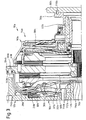
- a dual clutch assembly is designated 10.
- the dual clutch assembly 10 includes two system areas. On the one hand, this is a torsional vibration damper arrangement 12, here designed as a dual mass flywheel and, on the other hand, a double clutch 14.
- the torsional vibration damper arrangement 12 comprises a primary side 16, which essentially comprises a primary mass 18 and, fixedly connected thereto by screw bolts 20, a central disk element 22. By the bolts 20, the primary side 16 rotatably coupled to a drive member, such as a crankshaft of an internal combustion engine, coupled.
- a drive member such as a crankshaft of an internal combustion engine
- the torsional vibration damper assembly 12 further comprises a secondary side 24.
- This is essentially formed of two formed for example by forming sheet metal parts cover disk elements 26, 28. In their radially inner region these two cover disk elements 26, 28 lie on both sides of the central disk element 22. Radially outward they are, for example Screwing, riveting, welding or the like. firmly connected.
- spring windows 30, 32, 34 are provided at a plurality of circumferential positions.
- the spring windows 30, 32, 34 have mutually corresponding circumferential extents - with respect to a rotation axis A - and serve to receive respective damper springs 36, which form a damper element arrangement 37 in their entirety.
- these damper springs 36 are received under compression in the spring windows 30, 32, 34.
- the cover disk elements 26, 28 are rotatable under compression of these springs 36 with respect to the central disk element 32, whereby basically the primary side 16 with respect to the secondary side 24 about the rotational axis A is rotatable.
- a permanent or delayed acting friction device 38 of known type can act between the primary side 16 and the secondary side 24.
- the double clutch 14 essentially comprises two coupling regions 40, 42.
- the first coupling region 40 has a pressure plate 44, which is secured by tangential leaf springs or the like. rotatably with an annular disk-like abutment plate 46, with respect to this, however, is coupled axially movable.
- An actuating force transmission arrangement 48 of the first coupling region 40 comprises two, for example, pot-shaped force transmission parts 50, 52 which axially bridge the abutment plate 46.
- the force transmission element 50 is supported on the pressure plate 48, for example via a wear adjustment device.
- the force transmission element 52 is under the action of a Kraftbeetzleyungsan Aunt 54, which in turn is supported on a bottom portion 56 of a fixedly connected to the abutment plate 46 housing assembly 58.
- Actuator mechanism 60 biases the radially inner portion of force application assembly 54, wherein actuator mechanism 60 is shown here only symbolically and is substantially represented by a rotary decoupling bearing axially displaceable along a support member 62 for engaging operations about the radially inner portion of the force application assembly 54 in the direction of the Torsionsschwingungsdämpferan Aunt 12 to move and thereby move the actuating force transmission assembly 48 in the opposite direction and to move the pressure plate 48 toward the abutment plate 46 to.
- the friction linings 64 of a clutch disc 66 are clamped and a torque transmitted via this first clutch portion 40 to a non-rotatably coupled to the clutch disc transmission input shaft.
- the second coupling portion 42 also has a pressure plate 68 which is rotatably coupled to the abutment plate 46 and the housing 58, for example, again via tangential leaf springs or the like, with respect to this assembly, however, in the direction of the axis of rotation A is displaced.
- a Kraftbeetzungsan extract 70 of the second coupling portion 42 is radially outwardly supported on the bottom portion 56 of the housing 58 and radially further inside the pressure plate 68 act.
- an actuator mechanism 72 engages, such that upon movement of the mechanism also substantially represented by a rotary decoupling bearing, that bearing may in turn be displaced along the axis of the support member 62 and by movement of the force application assembly 70 in the direction can move to the pressure plate 68 to this in the direction of the abutment plate 46.
- the above-described dual clutch 10 as well as the previously described torsional vibration damper 12 may be configured differently.
- the double clutch in place of the previously described normal-open structure, in which an engagement force in the respective actuator mechanisms 60, 72 must be generated when using force accumulators at least one of the coupling portions 40, 42 may be formed as a normal-closed system.
- the housing 58 is supported via another rotary decoupling bearing 88 both axially and radially on the support member 62, which in turn is fixedly supported relative to the gear housing 80.
- the secondary side 24 is substantially fixedly connected to the input portion 90 of the dual clutch 10, which input portion 90 in turn is axially and radially fixed relative to the gear housing 80, with respect to this but also rotatably supported.
- the input area 90 of the double clutch 10 essentially comprises the abutment plate 46, the housing 58 and the components coupled therewith in a rotationally fixed manner, in particular the pressure plates 48, 68.
- various actuation system components such as actuation force transfer assembly 48, may be attributed to this entryway 90.
- This construction makes it possible to compensate for an axial offset or an axial inclination between the drive shaft and the output shafts, since relative movements between the primary side 16 and the secondary side 24 occur, in particular in the region of the torsional vibration damper arrangement 12 can, both in the radial and in the axial direction. Also, the implementation of wobbling in this area is possible.
- this dual clutch assembly 10 is carried out such that first the Torsionsschwingungsdämpferan extract 12 is radially inwardly connected by the bolts 20 to the drive unit. Subsequently, the dual clutch 14 already assembled with a transmission is introduced axially, and then the screw connection can be produced by means of the threaded bolts 86.
- this screw has both a rotary coupling function, as well as the function of the axial fixing.
- FIG. 2 shows an embodiment of a dual-clutch arrangement according to the invention, in which components which correspond to components described above with regard to construction or function are designated by the same reference number with the addition of an appendix "a".
- the basic structure here corresponds to that described above, so that only the differences are discussed.
- the double clutch 14a is coupled in the input region 90a, here in the region of the abutment plate 46a, to the mass portion 92a of the secondary side 24a.
- an elastically effective coupling arrangement 98a is provided.
- This may, for example, on the abutment plate 46a comprise a plurality of coupling pins 100a, which engage in the mass portion 92a provided or partially embedded therein elastomeric material 102a.
- the input portion 90a of the dual clutch 14a is elastically coupled to the secondary side 24a of the torsional vibration damper assembly 12a.
- This can, for example, at the carrier element 78a already mentioned above again comprise coupling pins 106a which engage in elastomeric material 108a.
- This elastomeric material 108a is supported on and partially embedded in the gear housing 80a.
- the dual clutch 14a is first set again on the transmission, while the Torsionsschwingungsdämpferan Aunt 12a is fixed to the drive unit. These two system areas are then brought axially together so that the pins 100a are inserted into the elastomeric material 102a. In this way, the pins 100a with the elastomeric material 102a simultaneously also fulfill the function of the rotary coupling.
- any elastomeric material is used here can, which can absorb corresponding loads, such as natural or synthetic rubber material.
- this elastomeric material overmolded metal bushings can be provided preferably at several circumferential positions with this elastomeric material overmolded metal bushings.
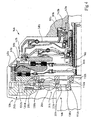
- FIG. 1 A further embodiment of a dual-clutch arrangement according to the invention is shown in FIG.
- Components which correspond to the above-described components in terms of structure and function are described by the same reference numeral with the addition of an appendix "b".
- appendix "b" the addition of an appendix
- the secondary side 24b of the torsional vibration damper arrangement 12b is via a bearing arrangement essentially comprising a bearing ring 110b with respect to the primary side 16b, namely with respect to a radially inner cylindrical projection 112b of the mass part 18b supported: At its axial end, this cylindrical projection 112b has a crowned or convex curved end surface 114b.
- the bearing ring 110b Associated with this crowned or convexly curved surface 114b, the bearing ring 110b has a concavely curved annular surface 116b which rests against the surface 114b of the mass portion 18b.
- the cover disk element 28b of the secondary side 24b is supported in its radially inner region on the bearing ring 110b. Due to the already discussed with reference to FIG. 1 basic mobility of the two cover disk elements 26b, 28b with respect to the central disk element 22b, which is not hindered by the bearing ring 110b and its mobility on the convex surface 114b substantially, also here is a Taumelentkopplung between the primary side 16b and the secondary side 24b. Also, minor relative axial movements of these two assemblies may occur with respect to each other.
- the double clutch 14b is in turn with its input portion 90b on the support member 62b and the support member 78b with respect to a fixed assembly, so for example, the gear housing 80b, held.
- coupling pins 118 can be used as well as the bolts shown in Fig. 1.
- a defined support of the input area 90b that is essentially also the housing 58b and the abutment plate 46b is provided.
- a rotary driving coupling allowing such a decoupling is provided between the cover disk element 28b and the abutment plate 46b.
- pivotal coupling pins 120b are provided, which engage in associated openings of a radial flange 122b of the cover disk element 28b.
- a plate spring 124b which provides an axial bias for the secondary side 24b, so that a firm abutting contact between the two surfaces 114b, 116b is realized.
- the assembly of this embodiment is made by first screwing back the torsional vibration damper assembly 12b to the drive shaft. Thereafter, the already assembled with the transmission dual clutch 14b is brought axially and realized in the region of the pins 120b, the coupling with the cover plate element 28b.
- the secondary side 24b comprises two coaxially nested annular disk elements 130b and 132b.
- the annular disk element 130b is fixedly connected to the cover disk element 28b, for example by riveting, while the radially outer annular disk element 132b is firmly connected by screwing to the input region 90b of the double clutch 14b.
- annular disk elements 130b, 132b adjoin one another, they are decoupled from each other, for example, by toothing formations and optionally with the interposition of elastic materials, so that, in principle, a rotational drive function is realized by positive locking, but otherwise the inner annular disk element 130b with respect to the outer annular disk element 132b at least slightly tilted.
- a bearing ring 110b is provided on which now the inner annular disk element 130b of the secondary side 24b is supported on the one hand, and which in turn with a now convex curved surface 116b on a correspondingly concave surface 114b of the primary side 16b, namely at one with the Central disk element 22b by the bolt 20b coupled support member 138b, is supported.
- the inner annular disk element 130b, together with the two cover disk elements 26b, 28b can in turn be tilted relative to the primary side 16b.
- the input region 90b of the dual clutch 14b is supported in the region of its housing 58b via the rotary decoupling bearing 88b and the abovementioned support member 62b with respect to the gear housing 80b, wherein a biasing spring 140b ensures that the entire input portion 90b biased towards the Torsionsschwingungsdämpferantechnisch 12b is.
- a biasing spring 140b ensures that the bearing ring 110b in fixed bearing contact with the surface 114b remains on the support element 138b. In the construction of this system, the procedure is again such that initially the torsional vibration damper arrangement 12b is fixed to the drive element.
- the dual clutch 14b already assembled with the transmission is introduced, the outer annular disk element 132b already being firmly connected to the abutment plate 46b and, as can be seen in FIG. 4, itself forming an abutment plate for the first coupling region 40b.
- the two annular disk elements 130b, 132b then engage in coupling engagement in their coupling region 134b, while retaining the aforesaid wobble of the secondary side 24b to a limited extent.
- the present invention provides various possibilities for coupling different system areas of a dual clutch arrangement, which either avoid overdetermination in the definition and thus allow compensating movements even when axial misalignment or axial misalignment occurs, or nevertheless allow a certain relative movement if redundancy is present due to elastic connection of different system areas ,
Landscapes
- Engineering & Computer Science (AREA)
- General Engineering & Computer Science (AREA)
- Mechanical Engineering (AREA)
- Mechanical Operated Clutches (AREA)
Claims (4)
- Ensemble d'embrayage double, comprenant:- un ensemble (12a) d'amortisseur de vibrations de torsion, avec un côté primaire (16a) qui peut être accouplé fixement à un organe d'entraînement en rotation conjointe autour d'un axe de rotation (A), et avec un côté secondaire (24a) qui est rotatif par rapport au côté primaire (16a) autour de l'axe de rotation (A) à l'encontre de l'action d'un ensemble (37a) d'éléments amortisseurs,- un embrayage double (14a) avec une région d'entrée (90a) et deux régions de sortie (66a, 76a), chacune des régions de sortie (66a, 76a) pouvant être accouplée en solidarité de rotation à l'un de deux organes menés,caractérisé en ce que la région d'entrée (90a) de l'embrayage double (14a) est soutenue par rapport au côté secondaire (24a) de l'ensemble (12a) d'amortisseur de vibrations de torsion d'une part et par rapport à un sous-ensemble fixe (80a) d'autre part par l'intermédiaire d'un ensemble d'accouplement élastique respectif (98a, 104a), sachant que les ensembles d'accouplement élastiques (98a, 104a) autorisent un mouvement de la région d'entrée (90a) de l'embrayage double (14a) en direction radiale et/ou en direction axiale.
- Ensemble d'embrayage double selon la revendication 1, caractérisé en ce que le sous-ensemble fixe (80a) comprend un carter de boîte (80a).
- Ensemble d'embrayage double selon la revendication 1 ou 2, caractérisé en ce que le côté secondaire (24a) de l'ensemble (12a) d'amortisseur de vibrations de torsion est soutenu sur le côté primaire (16a) de l'ensemble (12a) d'amortisseur de vibrations de torsion par l'intermédiaire d'un palier axial (94a) et d'un palier radial (96a).
- Ensemble d'embrayage double, comprenant :- un ensemble (12b) d'amortisseur de vibrations de torsion, avec un côté primaire (16b) qui peut être accouplé fixement à un organe d'entraînement en rotation conjointe autour d'un axe de rotation (A), et avec un côté secondaire (24b) qui est rotatif par rapport au côté primaire (16b) autour de l'axe de rotation (A) à l'encontre de l'action d'un ensemble (37b) d'éléments amortisseurs,- un embrayage double (14b) avec une région d'entrée (90b) et deux régions de sortie (66b, 76b), chacune des régions de sortie (66b, 76b) pouvant être accouplée en solidarité de rotation à l'un de deux organes menés,caractérisé en ce que le côté secondaire (24b) de l'ensemble (12b) d'amortisseur de vibrations de torsion est soutenu par rapport au côté primaire (16b) de l'ensemble (12b) d'amortisseur de vibrations de torsion par l'intermédiaire d'un ensemble (110b) de palier axial/radial qui autorise un basculement du côté secondaire (24b) par rapport au côté primaire (16b), sachant que le côté secondaire (24b) de l'ensemble (12b) d'amortisseur de vibrations de torsion est accouplé en solidarité de rotation à la région d'entrée (90b) de l'embrayage double (14b) par l'intermédiaire d'un ensemble d'accouplement (134b) qui autorise un basculement du côté secondaire (24b) par rapport à la région d'entrée (90b).
Applications Claiming Priority (3)
| Application Number | Priority Date | Filing Date | Title |
|---|---|---|---|
| DE10254900A DE10254900A1 (de) | 2002-11-22 | 2002-11-22 | Doppelkupplungsanordnung |
| DE10254900 | 2002-11-22 | ||
| PCT/EP2003/012869 WO2004048794A1 (fr) | 2002-11-22 | 2003-11-18 | Systeme a double embrayage |
Publications (2)
| Publication Number | Publication Date |
|---|---|
| EP1563198A1 EP1563198A1 (fr) | 2005-08-17 |
| EP1563198B1 true EP1563198B1 (fr) | 2007-04-04 |
Family
ID=32240387
Family Applications (1)
| Application Number | Title | Priority Date | Filing Date |
|---|---|---|---|
| EP03775366A Expired - Lifetime EP1563198B1 (fr) | 2002-11-22 | 2003-11-18 | Systeme a double embrayage |
Country Status (6)
| Country | Link |
|---|---|
| US (1) | US7264100B2 (fr) |
| EP (1) | EP1563198B1 (fr) |
| AT (1) | ATE358786T1 (fr) |
| AU (1) | AU2003283408A1 (fr) |
| DE (2) | DE10254900A1 (fr) |
| WO (1) | WO2004048794A1 (fr) |
Families Citing this family (14)
| Publication number | Priority date | Publication date | Assignee | Title |
|---|---|---|---|---|
| FR2871106B1 (fr) * | 2004-06-03 | 2007-10-05 | Peugeot Citroen Automobiles Sa | Element de transmission a double embrayage pour chaine de traction hybride de vehicule automobile, procede de montage, et vehicule automobile equipe d'un tel element |
| FR2871205B1 (fr) * | 2004-06-03 | 2007-10-05 | Peugeot Citroen Automobiles Sa | Element de transmission a embrayages humides pour chaine de traction de vehicule automobile, et vehicule automobile equipe d'un tel element |
| ATE415572T1 (de) * | 2004-09-03 | 2008-12-15 | Luk Lamellen & Kupplungsbau | Drehmomentübertragungseinrichtung |
| DE102004044518B4 (de) * | 2004-09-15 | 2008-04-17 | Zf Friedrichshafen Ag | Betätigungseinrichtung für eine Doppelkupplung eines Kraftfahrzeuges |
| WO2007062618A1 (fr) * | 2005-12-03 | 2007-06-07 | Luk Lamellen Und Kupplungsbau Beteiligungs Kg | Dispositif de transfert de couple |
| KR100892693B1 (ko) * | 2006-10-31 | 2009-04-15 | 현대자동차주식회사 | 더블 클러치 변속기 |
| DE102008004150A1 (de) | 2007-01-31 | 2008-08-07 | Luk Lamellen Und Kupplungsbau Beteiligungs Kg | Drehmomentübertragungseinrichtung |
| WO2010006578A1 (fr) * | 2008-07-14 | 2010-01-21 | Luk Lamellen Und Kupplungsbau Beteiligungs Kg | Embrayage double |
| WO2010006580A1 (fr) * | 2008-07-14 | 2010-01-21 | Luk Lamellen Und Kupplungsbau Beteiligungs Kg | Embrayage double |
| DE102008034627A1 (de) * | 2008-07-25 | 2010-01-28 | Schaeffler Kg | Wälzlager mit Flansch |
| DE112009001808A5 (de) * | 2008-08-22 | 2011-04-28 | Schaeffler Technologies Gmbh & Co. Kg | Doppelkupplung |
| US8413780B2 (en) | 2009-08-26 | 2013-04-09 | GM Global Technology Operations LLC | Dual clutch for a transmission having multiple input shafts |
| EP3123044B1 (fr) | 2014-03-27 | 2018-03-21 | Schaeffler Technologies GmbH & Co. KG | Plaque de pression et boîte de sécurité sous forme de composant commun |
| JP2016033003A (ja) * | 2014-07-29 | 2016-03-10 | アイシン・エィ・ダブリュ株式会社 | ハイブリッド駆動装置 |
Family Cites Families (7)
| Publication number | Priority date | Publication date | Assignee | Title |
|---|---|---|---|---|
| DE19713132A1 (de) * | 1997-03-27 | 1998-10-01 | Mannesmann Sachs Ag | Torsionsschwingungsdämpfer |
| DE50113312D1 (de) * | 2000-07-17 | 2008-01-10 | Zf Sachs Ag | Mehrfach-Kupplungseinrichtung in Kombination mit einer Torsionsschwingungsdämpferanordnung oder/und einer Elektromaschine |
| DE50001452D1 (de) | 2000-10-05 | 2003-04-17 | Ford Global Tech Inc | Doppelkupplung für ein Getriebe mit zwei Getriebeeingangswellen |
| JP5023372B2 (ja) * | 2000-11-22 | 2012-09-12 | シェフラー テクノロジーズ アクチエンゲゼルシャフト ウント コンパニー コマンディートゲゼルシャフト | クラッチ装置 |
| DE10134118B4 (de) | 2001-07-13 | 2013-02-21 | Volkswagen Ag | Doppelkupplung |
| US6830139B2 (en) * | 2001-10-09 | 2004-12-14 | Zf Sachs Ag | Multi-clutch arrangement |
| EP1302687B1 (fr) * | 2001-10-09 | 2006-11-08 | ZF Sachs AG | Dispositif à embrayages multiples |
-
2002
- 2002-11-22 DE DE10254900A patent/DE10254900A1/de not_active Ceased
-
2003
- 2003-11-18 US US10/529,103 patent/US7264100B2/en not_active Expired - Lifetime
- 2003-11-18 AT AT03775366T patent/ATE358786T1/de not_active IP Right Cessation
- 2003-11-18 WO PCT/EP2003/012869 patent/WO2004048794A1/fr not_active Ceased
- 2003-11-18 EP EP03775366A patent/EP1563198B1/fr not_active Expired - Lifetime
- 2003-11-18 DE DE50306980T patent/DE50306980D1/de not_active Expired - Lifetime
- 2003-11-18 AU AU2003283408A patent/AU2003283408A1/en not_active Abandoned
Non-Patent Citations (1)
| Title |
|---|
| None * |
Also Published As
| Publication number | Publication date |
|---|---|
| AU2003283408A1 (en) | 2004-06-18 |
| ATE358786T1 (de) | 2007-04-15 |
| DE10254900A1 (de) | 2004-06-03 |
| EP1563198A1 (fr) | 2005-08-17 |
| DE50306980D1 (de) | 2007-05-16 |
| US20060163019A1 (en) | 2006-07-27 |
| WO2004048794A1 (fr) | 2004-06-10 |
| US7264100B2 (en) | 2007-09-04 |
Similar Documents
| Publication | Publication Date | Title |
|---|---|---|
| EP2310704B1 (fr) | Embrayage double | |
| EP2109722B1 (fr) | Dispositif de transmission de couple | |
| EP1862689B1 (fr) | Agencement de transmission d'un couple de rotation pour le conducteur de commande d'un véhicule | |
| EP1479934B1 (fr) | Système de transmission | |
| DE69404572T2 (de) | Zweimassenschwungrad | |
| WO2007045418A1 (fr) | Dispositif d'accouplement servant a transmettre un couple de rotation | |
| EP1563198A1 (fr) | Systeme a double embrayage | |
| DE8504809U1 (de) | Geteiltes Schwungrad mit Rutschkupplung | |
| DE102009035912A1 (de) | Doppelkupplung | |
| DE102006063096B3 (de) | Mehrfach-Kupplungsmechanismus mit zweiteiliger Kupplungsscheibennabe | |
| DE10013576B4 (de) | Kupplungsaggregat | |
| EP1462675B1 (fr) | Amortisseur de vibrations de torsion | |
| EP1302687B1 (fr) | Dispositif à embrayages multiples | |
| EP2347145B1 (fr) | Amortisseur de vibrations torsionnelles pour la chaîne cinématique d'un véhicule | |
| EP1637766B1 (fr) | Amortisseur de vibrations de torsion | |
| EP1862685A1 (fr) | Agencement de transmission d'un couple de rotation pour le conducteur de commande d'un véhicule | |
| DE10003044A1 (de) | Torsionsschwingungsdämpfer | |
| DE19634382B4 (de) | Zweimassen-Dämpfungsschwungrad, insbesondere für Kraftfahrzeuge, mit Momentbegrenzungsmitteln | |
| EP1384911A2 (fr) | Ensemble à embrayage double | |
| DE10231513A1 (de) | Mehrfach-Kupplungsanordnung | |
| EP1862687A2 (fr) | Agencement de transmission d'un couple de rotation pour ligne de transmission de véhicule | |
| DE102004049238B4 (de) | Torsionsschwingungsdämpfer für eine Kupplungsscheibe | |
| DE69508557T2 (de) | Vorschaltbare dämpfungseinheit zur dämpfung von rotationsschwingungen | |
| EP1491792A1 (fr) | Systéme de transmission de couple dans la chaîne cinématique d'un véhicule à moteur | |
| DE102021107964A1 (de) | Drehmomentübertragungseinrichtung |
Legal Events
| Date | Code | Title | Description |
|---|---|---|---|
| PUAI | Public reference made under article 153(3) epc to a published international application that has entered the european phase |
Free format text: ORIGINAL CODE: 0009012 |
|
| 17P | Request for examination filed |
Effective date: 20050216 |
|
| AK | Designated contracting states |
Kind code of ref document: A1 Designated state(s): AT BE BG CH CY CZ DE DK EE ES FI FR GB GR HU IE IT LI LU MC NL PT RO SE SI SK TR |
|
| AX | Request for extension of the european patent |
Extension state: AL LT LV MK |
|
| DAX | Request for extension of the european patent (deleted) | ||
| GRAP | Despatch of communication of intention to grant a patent |
Free format text: ORIGINAL CODE: EPIDOSNIGR1 |
|
| GRAS | Grant fee paid |
Free format text: ORIGINAL CODE: EPIDOSNIGR3 |
|
| GRAA | (expected) grant |
Free format text: ORIGINAL CODE: 0009210 |
|
| AK | Designated contracting states |
Kind code of ref document: B1 Designated state(s): AT BE BG CH CY CZ DE DK EE ES FI FR GB GR HU IE IT LI LU MC NL PT RO SE SI SK TR |
|
| PG25 | Lapsed in a contracting state [announced via postgrant information from national office to epo] |
Ref country code: SI Free format text: LAPSE BECAUSE OF FAILURE TO SUBMIT A TRANSLATION OF THE DESCRIPTION OR TO PAY THE FEE WITHIN THE PRESCRIBED TIME-LIMIT Effective date: 20070404 Ref country code: FI Free format text: LAPSE BECAUSE OF FAILURE TO SUBMIT A TRANSLATION OF THE DESCRIPTION OR TO PAY THE FEE WITHIN THE PRESCRIBED TIME-LIMIT Effective date: 20070404 |
|
| REG | Reference to a national code |
Ref country code: GB Ref legal event code: FG4D Free format text: NOT ENGLISH |
|
| REG | Reference to a national code |
Ref country code: CH Ref legal event code: EP |
|
| REF | Corresponds to: |
Ref document number: 50306980 Country of ref document: DE Date of ref document: 20070516 Kind code of ref document: P |
|
| REG | Reference to a national code |
Ref country code: IE Ref legal event code: FG4D Free format text: LANGUAGE OF EP DOCUMENT: GERMAN |
|
| GBT | Gb: translation of ep patent filed (gb section 77(6)(a)/1977) |
Effective date: 20070604 |
|
| REG | Reference to a national code |
Ref country code: HU Ref legal event code: AG4A Ref document number: E001570 Country of ref document: HU |
|
| PG25 | Lapsed in a contracting state [announced via postgrant information from national office to epo] |
Ref country code: SE Free format text: LAPSE BECAUSE OF FAILURE TO SUBMIT A TRANSLATION OF THE DESCRIPTION OR TO PAY THE FEE WITHIN THE PRESCRIBED TIME-LIMIT Effective date: 20070704 |
|
| PG25 | Lapsed in a contracting state [announced via postgrant information from national office to epo] |
Ref country code: ES Free format text: LAPSE BECAUSE OF FAILURE TO SUBMIT A TRANSLATION OF THE DESCRIPTION OR TO PAY THE FEE WITHIN THE PRESCRIBED TIME-LIMIT Effective date: 20070715 |
|
| ET | Fr: translation filed | ||
| PG25 | Lapsed in a contracting state [announced via postgrant information from national office to epo] |
Ref country code: PT Free format text: LAPSE BECAUSE OF FAILURE TO SUBMIT A TRANSLATION OF THE DESCRIPTION OR TO PAY THE FEE WITHIN THE PRESCRIBED TIME-LIMIT Effective date: 20070904 |
|
| NLV1 | Nl: lapsed or annulled due to failure to fulfill the requirements of art. 29p and 29m of the patents act | ||
| REG | Reference to a national code |
Ref country code: IE Ref legal event code: FD4D |
|
| PG25 | Lapsed in a contracting state [announced via postgrant information from national office to epo] |
Ref country code: DK Free format text: LAPSE BECAUSE OF FAILURE TO SUBMIT A TRANSLATION OF THE DESCRIPTION OR TO PAY THE FEE WITHIN THE PRESCRIBED TIME-LIMIT Effective date: 20070404 Ref country code: BG Free format text: LAPSE BECAUSE OF FAILURE TO SUBMIT A TRANSLATION OF THE DESCRIPTION OR TO PAY THE FEE WITHIN THE PRESCRIBED TIME-LIMIT Effective date: 20070704 Ref country code: NL Free format text: LAPSE BECAUSE OF FAILURE TO SUBMIT A TRANSLATION OF THE DESCRIPTION OR TO PAY THE FEE WITHIN THE PRESCRIBED TIME-LIMIT Effective date: 20070404 Ref country code: IE Free format text: LAPSE BECAUSE OF FAILURE TO SUBMIT A TRANSLATION OF THE DESCRIPTION OR TO PAY THE FEE WITHIN THE PRESCRIBED TIME-LIMIT Effective date: 20070404 Ref country code: CZ Free format text: LAPSE BECAUSE OF FAILURE TO SUBMIT A TRANSLATION OF THE DESCRIPTION OR TO PAY THE FEE WITHIN THE PRESCRIBED TIME-LIMIT Effective date: 20070404 |
|
| PLBE | No opposition filed within time limit |
Free format text: ORIGINAL CODE: 0009261 |
|
| STAA | Information on the status of an ep patent application or granted ep patent |
Free format text: STATUS: NO OPPOSITION FILED WITHIN TIME LIMIT |
|
| PG25 | Lapsed in a contracting state [announced via postgrant information from national office to epo] |
Ref country code: SK Free format text: LAPSE BECAUSE OF FAILURE TO SUBMIT A TRANSLATION OF THE DESCRIPTION OR TO PAY THE FEE WITHIN THE PRESCRIBED TIME-LIMIT Effective date: 20070404 |
|
| 26N | No opposition filed |
Effective date: 20080107 |
|
| PG25 | Lapsed in a contracting state [announced via postgrant information from national office to epo] |
Ref country code: GR Free format text: LAPSE BECAUSE OF FAILURE TO SUBMIT A TRANSLATION OF THE DESCRIPTION OR TO PAY THE FEE WITHIN THE PRESCRIBED TIME-LIMIT Effective date: 20070705 Ref country code: IT Free format text: LAPSE BECAUSE OF FAILURE TO SUBMIT A TRANSLATION OF THE DESCRIPTION OR TO PAY THE FEE WITHIN THE PRESCRIBED TIME-LIMIT Effective date: 20070404 |
|
| PG25 | Lapsed in a contracting state [announced via postgrant information from national office to epo] |
Ref country code: RO Free format text: LAPSE BECAUSE OF FAILURE TO SUBMIT A TRANSLATION OF THE DESCRIPTION OR TO PAY THE FEE WITHIN THE PRESCRIBED TIME-LIMIT Effective date: 20070404 |
|
| BERE | Be: lapsed |
Owner name: ZF SACHS A.G. Effective date: 20071130 |
|
| PG25 | Lapsed in a contracting state [announced via postgrant information from national office to epo] |
Ref country code: MC Free format text: LAPSE BECAUSE OF NON-PAYMENT OF DUE FEES Effective date: 20071130 |
|
| PG25 | Lapsed in a contracting state [announced via postgrant information from national office to epo] |
Ref country code: LI Free format text: LAPSE BECAUSE OF NON-PAYMENT OF DUE FEES Effective date: 20071130 Ref country code: CH Free format text: LAPSE BECAUSE OF NON-PAYMENT OF DUE FEES Effective date: 20071130 |
|
| REG | Reference to a national code |
Ref country code: CH Ref legal event code: PL |
|
| PG25 | Lapsed in a contracting state [announced via postgrant information from national office to epo] |
Ref country code: BE Free format text: LAPSE BECAUSE OF NON-PAYMENT OF DUE FEES Effective date: 20071130 |
|
| PG25 | Lapsed in a contracting state [announced via postgrant information from national office to epo] |
Ref country code: EE Free format text: LAPSE BECAUSE OF FAILURE TO SUBMIT A TRANSLATION OF THE DESCRIPTION OR TO PAY THE FEE WITHIN THE PRESCRIBED TIME-LIMIT Effective date: 20070404 |
|
| PG25 | Lapsed in a contracting state [announced via postgrant information from national office to epo] |
Ref country code: AT Free format text: LAPSE BECAUSE OF NON-PAYMENT OF DUE FEES Effective date: 20071118 |
|
| PG25 | Lapsed in a contracting state [announced via postgrant information from national office to epo] |
Ref country code: CY Free format text: LAPSE BECAUSE OF FAILURE TO SUBMIT A TRANSLATION OF THE DESCRIPTION OR TO PAY THE FEE WITHIN THE PRESCRIBED TIME-LIMIT Effective date: 20070404 |
|
| PG25 | Lapsed in a contracting state [announced via postgrant information from national office to epo] |
Ref country code: LU Free format text: LAPSE BECAUSE OF NON-PAYMENT OF DUE FEES Effective date: 20071118 |
|
| PG25 | Lapsed in a contracting state [announced via postgrant information from national office to epo] |
Ref country code: TR Free format text: LAPSE BECAUSE OF FAILURE TO SUBMIT A TRANSLATION OF THE DESCRIPTION OR TO PAY THE FEE WITHIN THE PRESCRIBED TIME-LIMIT Effective date: 20070404 |
|
| REG | Reference to a national code |
Ref country code: DE Ref legal event code: R081 Ref document number: 50306980 Country of ref document: DE Owner name: ZF FRIEDRICHSHAFEN AG, DE Free format text: FORMER OWNER: ZF SACHS AG, 97424 SCHWEINFURT, DE Effective date: 20121030 |
|
| REG | Reference to a national code |
Ref country code: HU Ref legal event code: GB9C Owner name: ZF FRIEDRICHSHAFEN AG, DE Free format text: FORMER OWNER(S): ZF SACHS AG, DE Ref country code: HU Ref legal event code: FH1C Free format text: FORMER REPRESENTATIVE(S): MESZAROSNE DONUSZ KATALIN, S.B.G. & K. SZABADALMI UEGYVIVOEI IRODA, HU Representative=s name: DANUBIA SZABADALMI ES JOGI IRODA KFT., HU |
|
| REG | Reference to a national code |
Ref country code: FR Ref legal event code: TP Owner name: ZF FRIEDRICHSHAFEN AG, DE Effective date: 20150210 |
|
| REG | Reference to a national code |
Ref country code: GB Ref legal event code: 732E Free format text: REGISTERED BETWEEN 20150326 AND 20150401 |
|
| REG | Reference to a national code |
Ref country code: HU Ref legal event code: GB9C Owner name: ZF FRIEDRICHSHAFEN AG, DE Free format text: FORMER OWNER(S): ZF SACHS AG, DE; ZF FRIEDRICHSHAFEN AG, DE; ZF SACHS AG, DE |
|
| REG | Reference to a national code |
Ref country code: FR Ref legal event code: PLFP Year of fee payment: 13 |
|
| REG | Reference to a national code |
Ref country code: FR Ref legal event code: PLFP Year of fee payment: 14 |
|
| REG | Reference to a national code |
Ref country code: FR Ref legal event code: PLFP Year of fee payment: 15 |
|
| REG | Reference to a national code |
Ref country code: FR Ref legal event code: PLFP Year of fee payment: 16 |
|
| PGFP | Annual fee paid to national office [announced via postgrant information from national office to epo] |
Ref country code: GB Payment date: 20220930 Year of fee payment: 20 |
|
| PGFP | Annual fee paid to national office [announced via postgrant information from national office to epo] |
Ref country code: FR Payment date: 20220908 Year of fee payment: 20 |
|
| PGFP | Annual fee paid to national office [announced via postgrant information from national office to epo] |
Ref country code: DE Payment date: 20220921 Year of fee payment: 20 |
|
| PGFP | Annual fee paid to national office [announced via postgrant information from national office to epo] |
Ref country code: HU Payment date: 20221005 Year of fee payment: 20 |
|
| P01 | Opt-out of the competence of the unified patent court (upc) registered |
Effective date: 20230528 |
|
| REG | Reference to a national code |
Ref country code: DE Ref legal event code: R071 Ref document number: 50306980 Country of ref document: DE |
|
| REG | Reference to a national code |
Ref country code: GB Ref legal event code: PE20 Expiry date: 20231117 |
|
| PG25 | Lapsed in a contracting state [announced via postgrant information from national office to epo] |
Ref country code: GB Free format text: LAPSE BECAUSE OF EXPIRATION OF PROTECTION Effective date: 20231117 |
|
| PG25 | Lapsed in a contracting state [announced via postgrant information from national office to epo] |
Ref country code: GB Free format text: LAPSE BECAUSE OF EXPIRATION OF PROTECTION Effective date: 20231117 |