EP1563167B1 - Selbstregelnde turbine - Google Patents
Selbstregelnde turbine Download PDFInfo
- Publication number
- EP1563167B1 EP1563167B1 EP03767398A EP03767398A EP1563167B1 EP 1563167 B1 EP1563167 B1 EP 1563167B1 EP 03767398 A EP03767398 A EP 03767398A EP 03767398 A EP03767398 A EP 03767398A EP 1563167 B1 EP1563167 B1 EP 1563167B1
- Authority
- EP
- European Patent Office
- Prior art keywords
- turbine
- gas
- steam
- turbine blades
- blades
- Prior art date
- Legal status (The legal status is an assumption and is not a legal conclusion. Google has not performed a legal analysis and makes no representation as to the accuracy of the status listed.)
- Expired - Lifetime
Links
Images


Classifications
-
- F—MECHANICAL ENGINEERING; LIGHTING; HEATING; WEAPONS; BLASTING
- F01—MACHINES OR ENGINES IN GENERAL; ENGINE PLANTS IN GENERAL; STEAM ENGINES
- F01D—NON-POSITIVE DISPLACEMENT MACHINES OR ENGINES, e.g. STEAM TURBINES
- F01D5/00—Blades; Blade-carrying members; Heating, heat-insulating, cooling or antivibration means on the blades or the members
- F01D5/02—Blade-carrying members, e.g. rotors
- F01D5/04—Blade-carrying members, e.g. rotors for radial-flow machines or engines
- F01D5/043—Blade-carrying members, e.g. rotors for radial-flow machines or engines of the axial inlet- radial outlet, or vice versa, type
- F01D5/048—Form or construction
-
- F—MECHANICAL ENGINEERING; LIGHTING; HEATING; WEAPONS; BLASTING
- F01—MACHINES OR ENGINES IN GENERAL; ENGINE PLANTS IN GENERAL; STEAM ENGINES
- F01D—NON-POSITIVE DISPLACEMENT MACHINES OR ENGINES, e.g. STEAM TURBINES
- F01D17/00—Regulating or controlling by varying flow
- F01D17/10—Final actuators
- F01D17/12—Final actuators arranged in stator parts
- F01D17/14—Final actuators arranged in stator parts varying effective cross-sectional area of nozzles or guide conduits
- F01D17/146—Final actuators arranged in stator parts varying effective cross-sectional area of nozzles or guide conduits by throttling the volute inlet of radial machines or engines
-
- F—MECHANICAL ENGINEERING; LIGHTING; HEATING; WEAPONS; BLASTING
- F01—MACHINES OR ENGINES IN GENERAL; ENGINE PLANTS IN GENERAL; STEAM ENGINES
- F01D—NON-POSITIVE DISPLACEMENT MACHINES OR ENGINES, e.g. STEAM TURBINES
- F01D5/00—Blades; Blade-carrying members; Heating, heat-insulating, cooling or antivibration means on the blades or the members
- F01D5/02—Blade-carrying members, e.g. rotors
- F01D5/04—Blade-carrying members, e.g. rotors for radial-flow machines or engines
- F01D5/043—Blade-carrying members, e.g. rotors for radial-flow machines or engines of the axial inlet- radial outlet, or vice versa, type
-
- F—MECHANICAL ENGINEERING; LIGHTING; HEATING; WEAPONS; BLASTING
- F05—INDEXING SCHEMES RELATING TO ENGINES OR PUMPS IN VARIOUS SUBCLASSES OF CLASSES F01-F04
- F05D—INDEXING SCHEME FOR ASPECTS RELATING TO NON-POSITIVE-DISPLACEMENT MACHINES OR ENGINES, GAS-TURBINES OR JET-PROPULSION PLANTS
- F05D2270/00—Control
- F05D2270/30—Control parameters, e.g. input parameters
- F05D2270/304—Spool rotational speed
-
- Y—GENERAL TAGGING OF NEW TECHNOLOGICAL DEVELOPMENTS; GENERAL TAGGING OF CROSS-SECTIONAL TECHNOLOGIES SPANNING OVER SEVERAL SECTIONS OF THE IPC; TECHNICAL SUBJECTS COVERED BY FORMER USPC CROSS-REFERENCE ART COLLECTIONS [XRACs] AND DIGESTS
- Y02—TECHNOLOGIES OR APPLICATIONS FOR MITIGATION OR ADAPTATION AGAINST CLIMATE CHANGE
- Y02E—REDUCTION OF GREENHOUSE GAS [GHG] EMISSIONS, RELATED TO ENERGY GENERATION, TRANSMISSION OR DISTRIBUTION
- Y02E10/00—Energy generation through renewable energy sources
- Y02E10/40—Solar thermal energy, e.g. solar towers
- Y02E10/46—Conversion of thermal power into mechanical power, e.g. Rankine, Stirling or solar thermal engines
Definitions
- the DE 42 00507 A1 discloses a turbine with many geometric adjustment options. Due to the impeller adjustment 3a, the passage gap or size and at the same time the turbine blade length 2 or blade length and the spiral 14 are not changed independently via the leaf spring 9.
- the US 2 442 783 describes a self-regulating turbine according to the preamble of claim 1, wherein the rotor has turbine blades with flexible metal blades, which can change in shape depending on the rotor speed, resulting in an automatic speed control of the turbine.
- the invention is based on the object, especially for a turbine, the variable daily and annual gear load and a possible pulsed operation to adapt the turbine geometry to an optimal efficiency.
- the task set was a self-adapting turbine with almost constant speed and variable torque invent, wherein angularly adjustable vanes and / or blades in view of the required robustness and small size had to be disregarded.
- variable guide vanes for the purpose of changing the angle of attack and the flow velocity has long been tried and tested in known solution concepts.
- Turbine blade sections are designed to be retractable in a negative shape co-rotating axially as an impeller and in a last section via a flow-shaped central flow channel of the impeller go over, in which the turbine blades running from the inside to the outside are again designed retractable in the negative mold.
- the two, the turbine blades supporting rotary body with the turbine blades receiving negative mold in the form of an impeller form an assembly that are biased by one or more springs such that with increasing gas or vapor streams, the turbine blades partially or are given freely.
- the one or more stators and rotors of a turbine set are arranged in one plane and, depending on the amount of gas or steam, the free gap available in the plane of rotation is controlled automatically by a temperature-controlled and pressure-controlled spring force.
- a further embodiment of the invention consists in that the outer wall of the turbine outlet channel has seabed elements whose outer side is formed by a channel through which the working medium of the secondary circuit flows before entering the heat exchanger.
- Another particularly advantageous embodiment of the invention is that either a rotating turbine base plate on the side facing away from the turbine blades or the rotating impeller on the outside of permanent magnets of alternating polarity and against the Rotation gap the excitation windings of the generator are mounted.
- the absorber are completed at the upper edge of the housing with Seebeck electroden that are directly on the outside shaded forcibly cooled by air.
- the above-mentioned measures mean that the turbine, which adapts itself to different load conditions, quickly reaches its nominal speed even with small steam or gas mass flows, and the generator connected to the turbine likewise quickly reaches its nominal voltage.
- a speed limit of the turbine is achieved by controlling the flow of current through the generator by suitable voltage controlled control and the increasing current flow opposes the moment of the turbine with a suitably high electromagnetic moment.
- the outer wall of the turbine outlet channel allows the passage of heat through Peltier elements to a cooling channel of the Working medium of the secondary circuit is flowed through before entering the heat exchanger. This allows a further power generation in the preferred temperature difference of 150 ° C to 30 ° C.
- the self-adapting turbine should preferably be used for power generation with solar absorbers, but is equally applicable to other operating purposes with changing loads. With a suitable choice of material, the operation with hot gas from combustion processes is conceivable.
- the invention completing devices are provided for optimal operation of the solar absorber in response to the solar irradiation.
- the solar absorber is intended to equip the solar absorber at the upper end of the housing with a Peltier heat exchanger element whose warm side closes the solar absorber housing inside and the outer side shaded and forcibly thermally ventilated and thus cooled.
- a heat exchanger is further provided after the turbine and generator set, which cools the selected working medium again to the absorber inlet temperature and the heat exchange energy obtained, for example. a heat cycle or a heat storage provides.
- the working medium may be a gas or a fluid which evaporates in the absorber and condenses again in the turbine downstream of the heat exchanger.
- the desired working direction of the working medium is ensured by a check valve at the bottom of the working medium in the solar absorber, which allows only the inflow from below into the absorber.
- the absorber tubes lying in or on the absorber surface can be used to bring about a better heat transfer from the absorber surface through the absorber tube wall surface to the working medium to be heated be filled well gas or vapor-permeable and good heat transfer filling material such as copper wool.
- the absorber tube can also be an extruded hollow profile with star-shaped individual sections in order to provide the largest possible heat transfer surface available.
- an automatic device in which the interior of the absorber tubes is connected to a pressure regulating body, which is connected via a gas and vapor impermeable membrane with the working medium of the secondary circuit. At low flow temperatures, the membrane is stretched over a bimetallic spring, thus lowering the pressure inside the evaporation device.
Landscapes
- Engineering & Computer Science (AREA)
- Mechanical Engineering (AREA)
- General Engineering & Computer Science (AREA)
- Engine Equipment That Uses Special Cycles (AREA)
- Control Of Turbines (AREA)
Description
- Die
DE 42 00507 A1 offenbart eine Turbine mit sehr vielen geometrischen Einstellmöglichkeiten. Durch die Laufradverstellung 3a wird der Durchlassspalt oder -größe und gleichzeitig die Turbinenschaufellänge 2 oder -blattlänge und die Spirale 14 über die Blattfeder 9 nicht selbständig verändert. - Selbständige geometrische Veränderungen offenbaren die Schriften
US 3 149 820 undUS 4 540 337 . - Diese Schriften stellen nur die Auswahl von vielen bekannten technischen Lösungen dar.
- Die
US 2 442 783 beschreibt eine selbstregelnde Turbine gemäß dem Oberbegriff des Anspruchs 1, bei der der Rotor Turbinenschaufeln mit flexiblen Metallblättern aufweist, die sich abhängig von der Rotordrehzahl in ihrer Form ändern können, wodurch sich eine automatische Geschwindigkeitsregelung der Turbine ergibt. - Der Erfindung liegt die Aufgabe zu Grunde, speziell für eine Turbine die variable Tages- und Jahresgangbelastung und einem möglichen Pulsbetrieb die Turbinengeometrie zu einem optimalen Wirkungsgrad anzupassen.
- Die gestellte Aufgabe war es also z.B. für einen Massenstrom von 0,5 bis 20,0 1/s zwischen 0,2 Mpa auf der Eingangsseite und 0,1 Mpa auf der Austrittseite eine sich selbst anpassende Turbine mit nahezu gleichbleibender Drehzahl bei variablem Drehmoment zu erfinden, wobei im Winkel verstellbare Leit- und /oder Laufschaufeln angesichts der geforderten Robustheit und kleinen Baugröße außer Betracht bleiben mussten.
- An bekannten Lösungskonzepten sind insbesondere die Verwendung von variablen Leitschaufeln zwecks Veränderung des Anströmwinkels und der Anströmgeschwindigkeit seit langem erprobt.
- Die bekannten Ausführungsformen von Turbinen zeigen jedoch bei der gestellten Aufgabe hinsichtlich des optimalen Wirkungsgrades den negativen Effekt, dass bei der gestellten Aufgabe aufgrund der im wesentlichen starren Geometrie des Turbinenläufers, besser der Turbinenschaufeln, nur zweimal täglich bei Verwendung eines vorgeschalteten Solarabsorbers als Dampf- oder Heißgaserzeuger das Wirkungsgradoptimum erreicht wird und die Turbine in der verbleibenden Zeit entweder deutlich im Unterlastbereich oder im Überlastbereich unwirtschaftlich arbeitet (s.a.
Abbildung 1 ).
- Zudem ist bei Verwendung einer Turbine nach einem Solarabsorber zu beachten, dass die Turbinengeometrie für einen mittleren optimalen Arbeitsbereich ausgelegt wird, der den Tages- und Jahresgang optimal nutzen sollte. Damit wird bei herkömmlicher Turbinengeometrie der optimale Arbeitspunkt relativ niedrig angesetzt werden. Im Ergebnis wird eine herkömmliche Turbine zu mindestens 90% der nutzbaren Zeit in deutlicher Entfernung von optimalen Betriebszuständen im Unterlast- oder Überlastbereich arbeiten, d.h. nur einen mittleren Wirkungsgrad von vielleicht 25% gegenüber erreichbaren 70% erzielen.
- Erkennbar können zur Anpassung der Turbine an wechselnde Betriebszustände mit großen Varianzen weitere Maßnahmen neben der möglichen Verwendung verstellbarer Leitschaufeln getroffen werden. Diese Maßnahmen betreffen insbesondere
- die Anpassung des Anströmkanales der Turbine sowie
- eine veränderliche Turbinenschaufellänge bei Radialturbinen sowie
- die elektronische Steuerung des im Generator erzeugten Stromes zwecks Drehzahlbegrenzung nach Erreichen der Nenndrehzahl und der Nennspannung sowie
- einen Seebeck-Wärme-Strom-Tauscher im Turbinenauslasskanal.
- Die oben genannte Aufgabe wird erfindungsgemäß dadurch gelöst, dass als eine Regelgröße zur Drehzahlbegrenzung der Turbine die Veränderung des Stromflusses in dem der Turbine nachgeschalteten Generator eingesetzt wird und bei radialer Anströmung der Turbine in einem ersten Abschnitt des Kanals zwischen den Turbinenblättern die von außen nach innen laufenden Turbinenschaufelabschnitte in einer axial als Impeller mitrotierenden Negativform versenkbar ausgestaltet sind und über einen strömungsgünstig ausgeformten zentralen Strömungskanal des Impellers in einen letzten Abschnitt übergehen, in dem die von innen nach außen laufenden Turbinenblätter wiederum versenkbar in der Negativform ausgestaltet sind.
- Weitere Ausgestaltungen der Erfindung ergeben sich aus den Unteransprüchen. Dabei kann insbesondere vorgesehen sein, dass die beiden, die Turbinenschaufeln tragenden Rotationskörper mit der die Turbinenschaufeln aufnehmenden Negativform in Form eines Impellers eine Baugruppe bilden, die durch jeweils eine oder mehrere Federn derart vorgespannt werden, dass bei zunehmenden Gas- oder Dampfströmen die Turbinenschaufeln teilweise oder ganz frei gegeben sind.
- Vorteilhaft kann es darüber hinaus auch sein, dass die einen oder mehrere Statoren und Rotoren eines Turbinensatzes in einer Ebene angeordnet sind und je nach Gas- oder Dampfmenge der in der Rotationsebene zur Verfügung stehende freie Spalt selbsttätig durch eine temperatur- und druckgesteuerte Federkraft geregelt wird.
- Mit diesen erfindungsgemäßen Maßnahmen lässt sich eine Anpassung an variable Gas- und Dampfmengen erreichen und die Turbine unterschiedlichen Lastzuständen angepasst werden.
- Eine weitere Ausgestaltung der Erfindung besteht darin, dass die äußere Wandung des Turbinenauslasskanals Seebeckelemente aufweist, deren Außenseite durch einen Kanal gebildet wird, der von dem Arbeitsmedium des Sekundärkreislaufes vor Eintritt in den Wärmetauscher durchströmt wird.
- Eine weitere besonders zweckmäßige Ausgestaltung der Erfindung besteht darin, dass entweder eine rotierende Turbinengrundplatte auf der den Turbinenschaufeln abgewandten Seite oder der rotierende Impeller auf der Außenseite Permanentmagnete abwechselnder Polarität aufweisen und gegenüber dem Rotationsspalt die Erregerwicklungen des Generators angebracht sind.
- Schließlich kann in weiterer vorteilhafter Ausgestaltung nach der Erfindung vorgesehen sein, dass die Absorber am oberen Gehäuserand mit Seebeckelementen abgeschlossen sind, die auf der Außenseite unmittelbar beschattet zwangsweise durch Luft gekühlt werden.
- Die oben genannten Maßnahmen führen dazu, dass die sich selbst an unterschiedliche Lastzustände anpassende Turbine auch bei kleinen Dampf- oder Gasmassenströmen schnell ihre Nenndrehzahl erreicht und der mit der Turbine verbundene Generator ebenfalls schnell seine Nennspannung erreicht. Eine Drehzahlbegrenzung der Turbine wird erreicht, in dem durch eine geeignete, spannungsgesteuerte Steuerung der Stromfluss durch den Generator gesteuert wird und der zunehmende Stromfluss dem Moment der Turbine ein geeignet hohes elektromagnetisches Moment entgegensetzt.
- Die äußere Wandung des Turbinenauslasskanales erlaubt den wärmedurchgang durch Peltierelemente zu einem Kühlkanal, der von dem Arbeitsmedium des Sekundärkreislaufes vor Eintritt in den Wärmetauscher durchströmt wird. Damit wird eine weitere Stromgewinnung in der bevorzugten Temperaturdifferenz von 150 °C zu 30 °C ermöglicht.
- Die sich selbst anpassende Turbine soll vorzugsweise zur Stromgewinnung mit Solarabsorbern eingesetzt werden, ist aber gleichermaßen auch für andere Betriebszwecke mit wechselnden Lasten einsetzbar. Bei geeigneter Werkstoffwahl ist auch der Betrieb mit Heißgas aus Verbrennungsprozessen vorstellbar.
- Bei dem Einsatz mit Solarabsorbern werden für eine optimale Betriebsführung des Solarabsorbers in Abhängigkeit von der Solareinstrahlung weitere notwendige, die Erfindung vervollständigende Vorrichtungen vorgesehen. So ist beabsichtigt, den Solarabsorber am oberen Gehäuseabschluß mit einem Peltier-Wärme-Stromtauscherelement auszustatten, dessen warme Seite das Solarabsorbergehäuse innen abschließt und dessen äußere Seite beschattet und zwangsweise thermisch belüftet und damit gekühlt wird.
- So ist weiter nach dem Turbinen- und Generatorsatz ein Wärmetauscher vorgesehen, der das jeweils gewählte Arbeitsmedium wieder auf die Absorbereintrittstemperatur abkühlt und die gewonnene Wärmetauscherenergie z.B. einem Wärmekreislauf oder einem Wärmespeicher zur Verfügung stellt.
- Hierbei kann das Arbeitsmedium ein Gas oder ein Fluid sein, das im Absorber verdampft und in dem der Turbine nachgeordneten Wärmetauscher wieder kondensiert.
Die gewünschte Arbeitsrichtung des Arbeitsmediums wird sichergestellt durch ein Rückschlagventil am unteren Eintritt des Arbeitsmediums in den Solarabsorber, das nur die von unten erfolgende Zuströmung in den Absorber zuläßt. - Die in oder auf der Absorberfläche aufliegenden Absorberrohre können zur Herbeiführung eines besseren Wärmeüberganges von der Absorberfläche durch die Absorberrohrwandfläche auf das zu erwärmende Arbeitsmedium mit einem gut gas- oder dampfdurchlässigen und gut wärmeübertragenden Füllmaterial wie z.B. Kupferwolle gefüllt sein. Das Absorberrohr kann auch ein stranggepresstes Hohlprofil mit sternförmigen Einzelsektionen sein, um eine möglichst große Wärmeübertragungsfläche zur Verfügung stellen zu können.
- Es erweist sich bei Verwendung eines zu verdampfenden Arbeitsmediums weiter als vorteilhaft, den Vorrichtungsinnendruck in den Absorberrohren variabel zu gestalten um in Abhängigkeit von der gemäß Sonneneinstrahlung erreichbaren Prozeßtemperatur eine optimale Dampfmenge erzeugen zu können. So würde Wasser bei Normaldruck erst bei 100 °C verdampfen, bekannte Kältemittel dagegen schon bei etwa 50 °C. Der Innendruck im Primärkreislauf soll so mit der Vorlauftemperatur des Sekundärkreislaufes abgestimmt sein, daß das Arbeitsmedium im Primärkreislauf einem Druck ausgesetzt wird, dessen zugehörige Siedetemperatur mehr als 5 °C über der Vorlauftemperatur des Sekundärkreislaufes liegt.
- Dies wird durch eine selbsttätige Vorrichtung erreicht, bei der das Innere der Absorberrohre mit einem Druckregelkörper verbunden ist, der über eine gas-und dampfundurchlässige Membran mit dem Arbeitsmedium des Sekundärkreislaufes verbunden ist. Bei niedrigen Vorlauftemperaturen wird die Membran über eine Bimetallfeder gespannt und damit der Druck im Inneren der Verdampfungsvorrichtung abgesenkt.
- Es erweist sich als besonders vorteilhaft bei wirkungsgradkritischen, niedrigen Arbeitstemperaturen und niedrigen Gas- oder Dampfmengen pro Zeiteinheit, das System im Pulsbetrieb zu fahren, in dem die Absorberrohre in einem gemeinsamen Absorberrohr zusammengeführt werden und dieses gemeinsame Absorberrohr erst mit einem federgesteuerten Rückschlagventil bei einem voreingestellten Druck öffnet und die durch den Energieeintrag erzeugte Gas-oder Dampfmenge impulsartig die Turbine beaufschlagt. Dieser Impulsbetrieb kann geglättet werden, in dem zwei oder mehr gemeinsame Absorberrohre abwechselnd zur Beaufschlagung der Turbine freigegeben werden.
- Die Erfindung und entsprechendes technisches Umfeld wird in sechs Zeichnungen dargestellt:
- Zeichnung 1
- Turbine mit axialer Anströmung und radialer Ausströmung
- Zeichnung 2
- Turbine mit versenkbaren Turbinenschaufeln
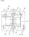
- Zeichnung 3
- Turbine mit radialer An- und Ausströmung
- Zeichnung 4
- Ausbildung der radialen Anströmkanäle
- Zeichnung 5
- Beschaufelung der Einlass-, Mittel- und Auslassturbinenteile
- Zeichnung 6
- Systemdarstellung gekoppelter Solarabsorber mit erfindungsgemäßer Turbine
-
- 1.
- Turbinensatz
- 2.
- Gas- bzw. Dampfeintrittsbohrung
- 3.
- Steuerzylinder
- 4.
- Turbinenstator
- 5.
- Turbinenrotor
- 6.
- Impeller mit Turbinenschaufelaufnahmen
- 7.
- Rotationskörper Turbineneinlass mit Turbinenschaufeln
- 8.
- Rotationskörper Turbinenauslass mit Turbinenschaufeln
- 9.
- Feder/-n zum Vorspannen der Rotationskörper gegen Impeller
- 10.
- veränderliches Höhenprofil Einlasskanal
- 11.
- veränderliches Tiefenprofil Einlasskanal
- 12.
- Spannfedern Höhen- bzw. Tiefenprofil
- 13.
- Drucksensitive, elastische Wandung Einlasskanal
- 14.
- Peltier-Wärme-Strom-Tauscher am Turbinenauslasskanal
- 15.
- Kühlungskanal des Seebecktauschers
- 16.
- Wärmetauscher zum Sekundärkreislauf
- 17.
- Fallrohr zum Absorbereintritt
- 18.
- Rückschlagventil
- 19.
- Absorberrohre
- 20.
- Druckregelbehälter
- 21.
- bimetallgesteuerte Membran
- 22.
- gas- bzw. dampfdurchlässiger Füllkörper
- 23.
- gemeinsame Absorberrohre
- 24.
- Gekoppelte Rückschlagventile für Pulsbetrieb
- 25.
- Seebeck-Wärme-Strom-Tauscherelement am Absorber
- 26.
- Temperatur- und druckelastisches Federblatt
Claims (6)
- Turbine zur Beaufschlagung mit unterschiedlichen Gas- oder Dampfmengen bei unterschiedlichen Temperaturen und Drücken, wobei in Abhängigkeit von der zur Verfügung stehenden erhitzten Gas- oder Dampfmenge nach Erreichen der Nenndrehzahl die Durchlassspaltgröße zwischen den Turbinenschaufeln oder die Turbinenblattneigung selbständig druck- und/oder temperaturabhängig eingestellt wird,
dadurch gekennzeichnet,
dass als eine Regelgröße zur Drehzahlbegrenzung der Turbine die Veränderung des Stromflusses in dem der Turbine nachgeschalteten Generator eingesetzt wird und bei radialer Anströmung der Turbine in einem ersten Abschnitt des Kanals zwischen den Turbinenblättern die von außen nach innen laufenden Turbinenschaufelabschnitte in einer axial als Impeller (6) mitrotierenden Negativform versenkbar ausgestaltet sind und über einen strömungsgünstig ausgeformten zentralen Strömungskanal des Impellers in einen letzten Abschnitt übergehen, in dem die von innen nach außen laufenden Turbinenblätter wiederum versenkbar in der Negativform ausgestaltet sind. - Turbine nach Anspruch 1,
dadurch gekennzeichnet, dass
die Turbine zwei Turbinenschaufeln tragenden Rotationskörper (7, 8) umfasst, und
dass die beiden, Rotationskörper (7,8) mit der die Turbinenschaufeln aufnehmenden Negativform in Form eines Impellers eine Baugruppe bilden, die durch jeweils eine oder mehrere Federn (9) derart vorgespannt werden, dass bei zunehmenden Gas- oder Dampfströmen die Turbinenschaufeln teilweise oder ganz frei gegeben sind. - Turbine nach Anspruch 1,
dadurch gekennzeichnet,
dass die einen oder mehrere Statoren (4) und Rotoren (5) eines Turbinensatzes in einer Ebene angeordnet sind und je nach Gas- oder Dampfmenge der in der Rotationsebene zur Verfügung stehende freie Spalt selbsttätig durch eine temperatur- und druckgesteuerte Federkraft geregelt wird. - Turbine nach einem der Ansprüche 1 bis 3,
dadurch gekennzeichnet,
dass die äußere Wandung des Turbinenauslasskanals Seebeckelemente (25) aufweist, deren Außenseite durch einen Kanal (15) gebildet wird, der von dem Arbeitsmedium des Sekundärkreislaufes vor Eintritt in den Wärmetauscher (16) durchströmt wird. - Turbine nach einem der Ansprüche 1 bis 4,
dadurch gekennzeichnet,
dass entweder eine rotierende Turbinengrundplatte auf der den Turbinenschaufeln abgewandten Seite oder der rotierende Impeller (6) auf der Außenseite Permanentmagnete abwechselnder Polarität aufweisen und gegenüber dem Rotationsspalt die Erregerwicklungen des Generators angebracht sind. - Turbine nach einem der Ansprüche 1 bis 5,
dadurch gekennzeichnet,
dass die Absorber (23) am oberen Gehäuserand mit Seebeckelementen (25) abgeschlossen sind, die auf der Außenseite unmittelbar beschattet zwangsweise durch Luft gekühlt werden.
Applications Claiming Priority (3)
| Application Number | Priority Date | Filing Date | Title |
|---|---|---|---|
| DE10251752A DE10251752C1 (de) | 2002-11-05 | 2002-11-05 | Selbstregelnde Turbine |
| DE10251752 | 2002-11-05 | ||
| PCT/DE2003/003607 WO2004042198A2 (de) | 2002-11-05 | 2003-10-30 | Selbstregelnde turbine |
Publications (2)
| Publication Number | Publication Date |
|---|---|
| EP1563167A2 EP1563167A2 (de) | 2005-08-17 |
| EP1563167B1 true EP1563167B1 (de) | 2008-07-09 |
Family
ID=28685402
Family Applications (1)
| Application Number | Title | Priority Date | Filing Date |
|---|---|---|---|
| EP03767398A Expired - Lifetime EP1563167B1 (de) | 2002-11-05 | 2003-10-30 | Selbstregelnde turbine |
Country Status (8)
| Country | Link |
|---|---|
| US (1) | US20050244268A1 (de) |
| EP (1) | EP1563167B1 (de) |
| CN (1) | CN100458105C (de) |
| AT (1) | ATE400729T1 (de) |
| AU (1) | AU2003291926A1 (de) |
| DE (3) | DE10251752C1 (de) |
| ES (1) | ES2307984T3 (de) |
| WO (1) | WO2004042198A2 (de) |
Families Citing this family (3)
| Publication number | Priority date | Publication date | Assignee | Title |
|---|---|---|---|---|
| DE102007045993A1 (de) * | 2007-09-26 | 2009-04-02 | Continental Automotive Gmbh | Laufradgehäuse mit einem variabel einstellbaren Strömungskanal |
| CN109505696B (zh) * | 2019-01-16 | 2021-07-02 | 势加透博洁净动力如皋有限公司 | 一种自动调节式涡轮增压机 |
| CN116378775B (zh) * | 2023-03-21 | 2025-09-12 | 西安交通大学 | 一种多部位联合调节的燃机叶片中弦冷却结构及控制方法 |
Family Cites Families (22)
| Publication number | Priority date | Publication date | Assignee | Title |
|---|---|---|---|---|
| DE448685C (de) * | 1925-11-10 | 1927-08-20 | Karl Wernert | Regelvorrichtung fuer die Saugseite von Kreiselpumpen, Verdichtern u. dgl. |
| US2442783A (en) * | 1944-07-01 | 1948-06-08 | Us Sec War | Turbine rotor |
| DE866145C (de) * | 1944-07-21 | 1953-02-09 | Daimler Benz Ag | Verfahren und Vorrichtung zum Anlassen von Zweikreis-Strahltriebwerken, insbesonderefuer Luftfahrzeuge |
| GB602706A (en) * | 1945-11-09 | 1948-06-01 | Albert Victor Gilbert | Improvements in or relating to gas turbines |
| DE819094C (de) * | 1949-05-26 | 1951-10-29 | Karl Dr-Ing Roeder | Turbinenstufe mit Duesenregelung und mindestens zwei Laufkraenzen |
| US4161371A (en) * | 1949-11-16 | 1979-07-17 | The United States Of America As Represented By The Secretary Of The Army | Self-regulating turbine |
| BE500182A (de) * | 1950-01-25 | |||
| US3352536A (en) * | 1952-06-11 | 1967-11-14 | Nils T Almquist | Self-regulating turbine |
| US2816731A (en) * | 1955-10-07 | 1957-12-17 | Gen Electric | Turbine speed control |
| US3073117A (en) * | 1958-04-01 | 1963-01-15 | Bendix Corp | Axially movable turbine for varying the turbine inlet in response to speed |
| GB905663A (en) * | 1959-06-01 | 1962-09-12 | Havilland Engine Co Ltd | Power plant including a gas turbine |
| US3149820A (en) * | 1961-06-28 | 1964-09-22 | Silencer Mfg Inc | Gas turbine speed control |
| DE1428192A1 (de) * | 1962-03-26 | 1969-03-06 | Mannesmann Meer Ag | Radialverdichter mit veraenderbarem Abstroemquerschnitt |
| US3901474A (en) * | 1973-12-27 | 1975-08-26 | Taimei Kinzoku Kogyo Kabushiki | Rotary valve |
| FR2285514A1 (fr) * | 1974-09-23 | 1976-04-16 | Belet Jean Yves | Regulateur de pression d'echappement pour turbocompresseurs |
| NO150135C (no) * | 1982-05-10 | 1984-08-22 | Kongsberg Vapenfab As | Anordning ved ramluftturbiner |
| DE4200507C2 (de) * | 1992-01-11 | 1994-02-17 | Armin Henry Kultscher | Variable Strömungsmaschine |
| US5794431A (en) * | 1993-07-14 | 1998-08-18 | Hitachi, Ltd. | Exhaust recirculation type combined plant |
| DE19938274A1 (de) * | 1999-08-12 | 2001-02-15 | Asea Brown Boveri | Vorrichtung und Verfahren zur geziehlten Spalteinstellung zwischen Stator- und Rotoranordnung einer Strömungsmaschine |
| US6367261B1 (en) * | 2000-10-30 | 2002-04-09 | Motorola, Inc. | Thermoelectric power generator and method of generating thermoelectric power in a steam power cycle utilizing latent steam heat |
| SE519673C2 (sv) * | 2000-12-22 | 2003-03-25 | Atlas Copco Tools Ab | Varvtalsregulator för en pneumatisk rotationsmotor |
| AT413743B (de) * | 2001-11-08 | 2006-05-15 | Tcg Unitech Ag | Radialpumpe |
-
2002
- 2002-11-05 DE DE10251752A patent/DE10251752C1/de not_active Expired - Fee Related
-
2003
- 2003-10-30 EP EP03767398A patent/EP1563167B1/de not_active Expired - Lifetime
- 2003-10-30 ES ES03767398T patent/ES2307984T3/es not_active Expired - Lifetime
- 2003-10-30 CN CNB2003801025561A patent/CN100458105C/zh not_active Expired - Fee Related
- 2003-10-30 WO PCT/DE2003/003607 patent/WO2004042198A2/de not_active Ceased
- 2003-10-30 AU AU2003291926A patent/AU2003291926A1/en not_active Abandoned
- 2003-10-30 DE DE10394044T patent/DE10394044D2/de not_active Expired - Fee Related
- 2003-10-30 AT AT03767398T patent/ATE400729T1/de not_active IP Right Cessation
- 2003-10-30 DE DE50310124T patent/DE50310124D1/de not_active Expired - Lifetime
-
2005
- 2005-05-04 US US11/121,644 patent/US20050244268A1/en not_active Abandoned
Also Published As
| Publication number | Publication date |
|---|---|
| EP1563167A2 (de) | 2005-08-17 |
| DE10394044D2 (de) | 2005-11-03 |
| WO2004042198A3 (de) | 2004-07-08 |
| ATE400729T1 (de) | 2008-07-15 |
| US20050244268A1 (en) | 2005-11-03 |
| WO2004042198A2 (de) | 2004-05-21 |
| DE10251752C1 (de) | 2003-10-30 |
| ES2307984T3 (es) | 2008-12-01 |
| AU2003291926A8 (en) | 2004-06-07 |
| CN100458105C (zh) | 2009-02-04 |
| CN1708634A (zh) | 2005-12-14 |
| DE50310124D1 (de) | 2008-08-21 |
| AU2003291926A1 (en) | 2004-06-07 |
Similar Documents
| Publication | Publication Date | Title |
|---|---|---|
| DE102004029505B4 (de) | Fluidmaschine zum Umsetzen von Wärmeenergie in mechanische Drehkraft | |
| DE2945404C2 (de) | Verfahren zum Betrieb einer kombinierten Gas-Dampfturbinenanlage und Gas-Dampfturbinenanlage zur Durchführung dieses Verfahrens | |
| EP3006682B1 (de) | Vorrichtung und Verfahren für den Betrieb einer Wärmeübergabestation | |
| WO2015078829A1 (de) | Wärmekraftwerk | |
| WO2011036136A1 (de) | Kraftwerksanlage mit überlast-regelventil | |
| DE3135154A1 (de) | "waermepumpe" | |
| EP1563167B1 (de) | Selbstregelnde turbine | |
| DE69514936T2 (de) | Kühlsystem und verfahren | |
| DE102007048274A1 (de) | Abgasturbolader | |
| CH702376A2 (de) | Erdwärmetauschersystem zur Verwendung in einem Gasturbinenkraftwerk. | |
| EP3222923A1 (de) | Belüftungssystem mit wärmetauscher | |
| DE102021200405B4 (de) | Druckerzeugungsvorrichtung, Kohlendioxid-Zyklusanlage und kombinierte Zyklusanlage | |
| DE102019213613A1 (de) | Verdampfer für eine Wärmepumpe oder Kältemaschine | |
| EP2730755B1 (de) | Anlage zur Nutzung von Wärmeenergie | |
| DE102020003407A1 (de) | Ringflüssigkeitsturbine einer Wärmepumpenanlage und Wärmepumpenanlage mit der Ringflüssigkeitsturbine | |
| DE102023126614A1 (de) | Wärmetauscher für eine Wärmepumpenanlage, Wärmepumpenanlage und Verwendung eines Toroidal-Gebläserades | |
| DE102010029108A1 (de) | Anordnung sowie Verfahren zum Umwandeln von Strömungsenergie eines Fluids | |
| DE102009050583B4 (de) | Einrichtung zur mechanischen oder elektrischen Energiegewinnung aus thermischer Energie | |
| DE102010033942A1 (de) | Verfahren zum Kühlen eines Generators | |
| EP0929737B1 (de) | Dampfturbine mit kondensator sowie verfahren zur kühlung einer dampfturbine im ventilationsbetrieb | |
| AT504762B1 (de) | Wärmepumpe | |
| DE10244677B4 (de) | Kondensator für Arbeitsmaschinen | |
| DE202023104488U1 (de) | Einrichtung zum Erzeugen von Wärme | |
| DE29901789U1 (de) | Kraftwärmevorrichtung | |
| DE102014008114A1 (de) | Elektrisch betriebene Motor-Pumpeneinheit |
Legal Events
| Date | Code | Title | Description |
|---|---|---|---|
| PUAI | Public reference made under article 153(3) epc to a published international application that has entered the european phase |
Free format text: ORIGINAL CODE: 0009012 |
|
| 17P | Request for examination filed |
Effective date: 20050603 |
|
| AK | Designated contracting states |
Kind code of ref document: A2 Designated state(s): AT BE BG CH CY CZ DE DK EE ES FI FR GB GR HU IE IT LI LU MC NL PT RO SE SI SK TR |
|
| AX | Request for extension of the european patent |
Extension state: AL LT LV MK |
|
| DAX | Request for extension of the european patent (deleted) | ||
| 17Q | First examination report despatched |
Effective date: 20060601 |
|
| GRAP | Despatch of communication of intention to grant a patent |
Free format text: ORIGINAL CODE: EPIDOSNIGR1 |
|
| GRAS | Grant fee paid |
Free format text: ORIGINAL CODE: EPIDOSNIGR3 |
|
| RAP1 | Party data changed (applicant data changed or rights of an application transferred) |
Owner name: DEUTSCHE ENERGIE HOLDING GMBH |
|
| RIN1 | Information on inventor provided before grant (corrected) |
Inventor name: PRIEBE, KLAUS-PETER |
|
| GRAA | (expected) grant |
Free format text: ORIGINAL CODE: 0009210 |
|
| AK | Designated contracting states |
Kind code of ref document: B1 Designated state(s): AT BE BG CH CY CZ DE DK EE ES FI FR GB GR HU IE IT LI LU MC NL PT RO SE SI SK TR |
|
| REG | Reference to a national code |
Ref country code: GB Ref legal event code: FG4D Free format text: NOT ENGLISH |
|
| REG | Reference to a national code |
Ref country code: CH Ref legal event code: EP |
|
| REF | Corresponds to: |
Ref document number: 50310124 Country of ref document: DE Date of ref document: 20080821 Kind code of ref document: P |
|
| REG | Reference to a national code |
Ref country code: IE Ref legal event code: FG4D Free format text: LANGUAGE OF EP DOCUMENT: GERMAN |
|
| REG | Reference to a national code |
Ref country code: GR Ref legal event code: EP Ref document number: 20080402459 Country of ref document: GR |
|
| REG | Reference to a national code |
Ref country code: ES Ref legal event code: FG2A Ref document number: 2307984 Country of ref document: ES Kind code of ref document: T3 |
|
| NLV1 | Nl: lapsed or annulled due to failure to fulfill the requirements of art. 29p and 29m of the patents act | ||
| PG25 | Lapsed in a contracting state [announced via postgrant information from national office to epo] |
Ref country code: NL Free format text: LAPSE BECAUSE OF FAILURE TO SUBMIT A TRANSLATION OF THE DESCRIPTION OR TO PAY THE FEE WITHIN THE PRESCRIBED TIME-LIMIT Effective date: 20080709 Ref country code: PT Free format text: LAPSE BECAUSE OF FAILURE TO SUBMIT A TRANSLATION OF THE DESCRIPTION OR TO PAY THE FEE WITHIN THE PRESCRIBED TIME-LIMIT Effective date: 20081209 |
|
| PG25 | Lapsed in a contracting state [announced via postgrant information from national office to epo] |
Ref country code: BG Free format text: LAPSE BECAUSE OF FAILURE TO SUBMIT A TRANSLATION OF THE DESCRIPTION OR TO PAY THE FEE WITHIN THE PRESCRIBED TIME-LIMIT Effective date: 20081009 Ref country code: FI Free format text: LAPSE BECAUSE OF FAILURE TO SUBMIT A TRANSLATION OF THE DESCRIPTION OR TO PAY THE FEE WITHIN THE PRESCRIBED TIME-LIMIT Effective date: 20080709 Ref country code: SI Free format text: LAPSE BECAUSE OF FAILURE TO SUBMIT A TRANSLATION OF THE DESCRIPTION OR TO PAY THE FEE WITHIN THE PRESCRIBED TIME-LIMIT Effective date: 20080709 |
|
| REG | Reference to a national code |
Ref country code: IE Ref legal event code: FD4D |
|
| BERE | Be: lapsed |
Owner name: DEUTSCHE ENERGIE HOLDING G.M.B.H. Effective date: 20081031 |
|
| PG25 | Lapsed in a contracting state [announced via postgrant information from national office to epo] |
Ref country code: IE Free format text: LAPSE BECAUSE OF FAILURE TO SUBMIT A TRANSLATION OF THE DESCRIPTION OR TO PAY THE FEE WITHIN THE PRESCRIBED TIME-LIMIT Effective date: 20080709 Ref country code: EE Free format text: LAPSE BECAUSE OF FAILURE TO SUBMIT A TRANSLATION OF THE DESCRIPTION OR TO PAY THE FEE WITHIN THE PRESCRIBED TIME-LIMIT Effective date: 20080709 Ref country code: DK Free format text: LAPSE BECAUSE OF FAILURE TO SUBMIT A TRANSLATION OF THE DESCRIPTION OR TO PAY THE FEE WITHIN THE PRESCRIBED TIME-LIMIT Effective date: 20080709 |
|
| PLBE | No opposition filed within time limit |
Free format text: ORIGINAL CODE: 0009261 |
|
| STAA | Information on the status of an ep patent application or granted ep patent |
Free format text: STATUS: NO OPPOSITION FILED WITHIN TIME LIMIT |
|
| PG25 | Lapsed in a contracting state [announced via postgrant information from national office to epo] |
Ref country code: MC Free format text: LAPSE BECAUSE OF NON-PAYMENT OF DUE FEES Effective date: 20081031 Ref country code: CZ Free format text: LAPSE BECAUSE OF FAILURE TO SUBMIT A TRANSLATION OF THE DESCRIPTION OR TO PAY THE FEE WITHIN THE PRESCRIBED TIME-LIMIT Effective date: 20080709 Ref country code: RO Free format text: LAPSE BECAUSE OF FAILURE TO SUBMIT A TRANSLATION OF THE DESCRIPTION OR TO PAY THE FEE WITHIN THE PRESCRIBED TIME-LIMIT Effective date: 20080709 Ref country code: SK Free format text: LAPSE BECAUSE OF FAILURE TO SUBMIT A TRANSLATION OF THE DESCRIPTION OR TO PAY THE FEE WITHIN THE PRESCRIBED TIME-LIMIT Effective date: 20080709 |
|
| REG | Reference to a national code |
Ref country code: CH Ref legal event code: PL |
|
| 26N | No opposition filed |
Effective date: 20090414 |
|
| PG25 | Lapsed in a contracting state [announced via postgrant information from national office to epo] |
Ref country code: BE Free format text: LAPSE BECAUSE OF NON-PAYMENT OF DUE FEES Effective date: 20081031 |
|
| PG25 | Lapsed in a contracting state [announced via postgrant information from national office to epo] |
Ref country code: LI Free format text: LAPSE BECAUSE OF NON-PAYMENT OF DUE FEES Effective date: 20081031 Ref country code: CH Free format text: LAPSE BECAUSE OF NON-PAYMENT OF DUE FEES Effective date: 20081031 |
|
| PG25 | Lapsed in a contracting state [announced via postgrant information from national office to epo] |
Ref country code: SE Free format text: LAPSE BECAUSE OF FAILURE TO SUBMIT A TRANSLATION OF THE DESCRIPTION OR TO PAY THE FEE WITHIN THE PRESCRIBED TIME-LIMIT Effective date: 20081009 Ref country code: AT Free format text: LAPSE BECAUSE OF NON-PAYMENT OF DUE FEES Effective date: 20081030 |
|
| PGFP | Annual fee paid to national office [announced via postgrant information from national office to epo] |
Ref country code: TR Payment date: 20091026 Year of fee payment: 7 |
|
| PGFP | Annual fee paid to national office [announced via postgrant information from national office to epo] |
Ref country code: FR Payment date: 20091110 Year of fee payment: 7 Ref country code: GB Payment date: 20091023 Year of fee payment: 7 Ref country code: IT Payment date: 20091027 Year of fee payment: 7 |
|
| PGFP | Annual fee paid to national office [announced via postgrant information from national office to epo] |
Ref country code: GR Payment date: 20091030 Year of fee payment: 7 |
|
| PG25 | Lapsed in a contracting state [announced via postgrant information from national office to epo] |
Ref country code: CY Free format text: LAPSE BECAUSE OF FAILURE TO SUBMIT A TRANSLATION OF THE DESCRIPTION OR TO PAY THE FEE WITHIN THE PRESCRIBED TIME-LIMIT Effective date: 20080709 Ref country code: LU Free format text: LAPSE BECAUSE OF NON-PAYMENT OF DUE FEES Effective date: 20081030 Ref country code: HU Free format text: LAPSE BECAUSE OF FAILURE TO SUBMIT A TRANSLATION OF THE DESCRIPTION OR TO PAY THE FEE WITHIN THE PRESCRIBED TIME-LIMIT Effective date: 20090110 |
|
| GBPC | Gb: european patent ceased through non-payment of renewal fee |
Effective date: 20101030 |
|
| PG25 | Lapsed in a contracting state [announced via postgrant information from national office to epo] |
Ref country code: GR Free format text: LAPSE BECAUSE OF NON-PAYMENT OF DUE FEES Effective date: 20110503 Ref country code: FR Free format text: LAPSE BECAUSE OF NON-PAYMENT OF DUE FEES Effective date: 20101102 |
|
| REG | Reference to a national code |
Ref country code: FR Ref legal event code: ST Effective date: 20110630 |
|
| PG25 | Lapsed in a contracting state [announced via postgrant information from national office to epo] |
Ref country code: GB Free format text: LAPSE BECAUSE OF NON-PAYMENT OF DUE FEES Effective date: 20101030 |
|
| PG25 | Lapsed in a contracting state [announced via postgrant information from national office to epo] |
Ref country code: IT Free format text: LAPSE BECAUSE OF NON-PAYMENT OF DUE FEES Effective date: 20101030 |
|
| PG25 | Lapsed in a contracting state [announced via postgrant information from national office to epo] |
Ref country code: TR Free format text: LAPSE BECAUSE OF NON-PAYMENT OF DUE FEES Effective date: 20101030 |
|
| PGFP | Annual fee paid to national office [announced via postgrant information from national office to epo] |
Ref country code: DE Payment date: 20120915 Year of fee payment: 10 |
|
| PGFP | Annual fee paid to national office [announced via postgrant information from national office to epo] |
Ref country code: ES Payment date: 20121023 Year of fee payment: 10 |
|
| REG | Reference to a national code |
Ref country code: DE Ref legal event code: R119 Ref document number: 50310124 Country of ref document: DE Effective date: 20140501 |
|
| PG25 | Lapsed in a contracting state [announced via postgrant information from national office to epo] |
Ref country code: DE Free format text: LAPSE BECAUSE OF NON-PAYMENT OF DUE FEES Effective date: 20140501 |
|
| REG | Reference to a national code |
Ref country code: ES Ref legal event code: FD2A Effective date: 20141107 |
|
| PG25 | Lapsed in a contracting state [announced via postgrant information from national office to epo] |
Ref country code: ES Free format text: LAPSE BECAUSE OF NON-PAYMENT OF DUE FEES Effective date: 20131031 |