EP1562246A2 - Flüssigbrennstoffzelle - Google Patents
Flüssigbrennstoffzelle Download PDFInfo
- Publication number
- EP1562246A2 EP1562246A2 EP05001786A EP05001786A EP1562246A2 EP 1562246 A2 EP1562246 A2 EP 1562246A2 EP 05001786 A EP05001786 A EP 05001786A EP 05001786 A EP05001786 A EP 05001786A EP 1562246 A2 EP1562246 A2 EP 1562246A2
- Authority
- EP
- European Patent Office
- Prior art keywords
- base material
- fuel cell
- fuel
- electrode
- cell
- Prior art date
- Legal status (The legal status is an assumption and is not a legal conclusion. Google has not performed a legal analysis and makes no representation as to the accuracy of the status listed.)
- Withdrawn
Links
Images




Classifications
-
- H—ELECTRICITY
- H01—ELECTRIC ELEMENTS
- H01M—PROCESSES OR MEANS, e.g. BATTERIES, FOR THE DIRECT CONVERSION OF CHEMICAL ENERGY INTO ELECTRICAL ENERGY
- H01M4/00—Electrodes
- H01M4/86—Inert electrodes with catalytic activity, e.g. for fuel cells
- H01M4/8605—Porous electrodes
-
- H—ELECTRICITY
- H01—ELECTRIC ELEMENTS
- H01M—PROCESSES OR MEANS, e.g. BATTERIES, FOR THE DIRECT CONVERSION OF CHEMICAL ENERGY INTO ELECTRICAL ENERGY
- H01M8/00—Fuel cells; Manufacture thereof
- H01M8/02—Details
- H01M8/0202—Collectors; Separators, e.g. bipolar separators; Interconnectors
- H01M8/023—Porous and characterised by the material
- H01M8/0234—Carbonaceous material
-
- H—ELECTRICITY
- H01—ELECTRIC ELEMENTS
- H01M—PROCESSES OR MEANS, e.g. BATTERIES, FOR THE DIRECT CONVERSION OF CHEMICAL ENERGY INTO ELECTRICAL ENERGY
- H01M8/00—Fuel cells; Manufacture thereof
- H01M8/10—Fuel cells with solid electrolytes
- H01M8/1004—Fuel cells with solid electrolytes characterised by membrane-electrode assemblies [MEA]
-
- H—ELECTRICITY
- H01—ELECTRIC ELEMENTS
- H01M—PROCESSES OR MEANS, e.g. BATTERIES, FOR THE DIRECT CONVERSION OF CHEMICAL ENERGY INTO ELECTRICAL ENERGY
- H01M8/00—Fuel cells; Manufacture thereof
- H01M8/10—Fuel cells with solid electrolytes
- H01M8/1009—Fuel cells with solid electrolytes with one of the reactants being liquid, solid or liquid-charged
- H01M8/1011—Direct alcohol fuel cells [DAFC], e.g. direct methanol fuel cells [DMFC]
-
- Y—GENERAL TAGGING OF NEW TECHNOLOGICAL DEVELOPMENTS; GENERAL TAGGING OF CROSS-SECTIONAL TECHNOLOGIES SPANNING OVER SEVERAL SECTIONS OF THE IPC; TECHNICAL SUBJECTS COVERED BY FORMER USPC CROSS-REFERENCE ART COLLECTIONS [XRACs] AND DIGESTS
- Y02—TECHNOLOGIES OR APPLICATIONS FOR MITIGATION OR ADAPTATION AGAINST CLIMATE CHANGE
- Y02E—REDUCTION OF GREENHOUSE GAS [GHG] EMISSIONS, RELATED TO ENERGY GENERATION, TRANSMISSION OR DISTRIBUTION
- Y02E60/00—Enabling technologies; Technologies with a potential or indirect contribution to GHG emissions mitigation
- Y02E60/30—Hydrogen technology
- Y02E60/50—Fuel cells
Definitions
- the present invention relates to a fuel cell using liquid fuel, more specifically to a fuel cell suitably used as an electric source for portable electronic apppliances such as cellular phones and note type personal computers and a small-sized portable electric source for appliances using small electric power.
- a fuel cell comprises a cell part on which an air electrode layer, an electrolyte layer and a fuel electrode layer are laminated, a fuel-supplying part for supplying fuel as a reducing agent to the fuel electrode layer and an air-supplying part for supplying air as an oxidizing agent to the air electrode layer, and it is an electric cell in which electrochemical reaction is caused in a cell between fuel and oxygen in the air to obtain electric power in the outside.
- Cells of various types are developed.
- sheet-like cells (unit cell) 1, 1--- having an electrolyte membrane/electrode junction assembly (MEA: membrane electrode assembly) are laminated, as shown in Fig. 17, via tabular separators 2, 2--- to attempt reduction in a size of a cell stack and increase in a output density thereof.
- auxiliary devices such as a pump and a blower are necessary in order to allow liquid fuel and oxidizing agent gas (for example; air and oxygen) to flow through passages 2a for the liquid fuel and passages 2b for the oxidizing agent gas which are formed in thin tabular separators 2 interposed between the unit cells 1.
- liquid fuel and oxidizing agent gas for example; air and oxygen
- a fuel cell for small-sized portable appliances is, for example, as shown in Fig, 18, a fuel cell of a self-operating type which has at least one vent hole 4 on a wall face of a liquid fuel vessel 3 and which installs plural sheet-like single cells (unit cells) 5, 5--- having MEA on the wall face of the above liquid fuel vessel 3 and electrically connects the each unit cells and which makes use of a capillary phenomenon of liquid fuel 6 and convention and diffusion of oxidizing agent gas without using auxiliary devices (for example, Japanese Patent Application Laid-Open No. 100315/2003).
- the sheet-like unit cells can not help being connected on a two-dimensional plane, and as a result, caused is the problem that cell junction (stacking) making effective use of a three-dimensional space can not be carried out.
- a fuel cell in which liquid fuel is introduced into a unit cell that contacts with a common absorber at one end of each unit cell by capillary force and in which the liquid fuel is then vaporized in a fuel-vaporizing layer and used (for example, Japanese Patent Application Laid-Open No. 102069/2001).
- a shortage in followability of fuel which is a fundamental problem is not improved, and it has the problems that liquid fuel is instably fed when the fuel is fed to a fuel electrode to bring about variation in an output value during operation and that it is difficult to reduce a size thereof to such an extent that it can be loaded in portable appliances while maintaining stable characteristics.
- the present invention intends to solve them, and an object thereof is to provide a fuel cell which attempts reduction in a size of the whole fuel cell system as an electric source for small-sized portable appliances and a rise in an output and which generates less noises.
- a fuel cell meeting the object described above can be obtained by assuming a structure which comprises a unit cell in which the respective layers of electrode/electrolyte/electrode are formed on the surface of a base material of specific physical properties having electric conductivity in a part or the whole part, or a connected assembly prepared by connecting two or more above unit cells and in which the above base material of the specific physical properties is impregnated with liquid fuel and an electrode surface formed on the outside surface of the base material is exposed to oxidizing agent gas.
- the present invention has come to be completed.
- the present invention comprises the following items (1) to (11).
- plural cells can be connected by only a part of cell end parts by allowing a carbonaceous porous body having electrical conductivity to have functions as an electrode ⁇ collector, an impregnating medium for liquid fuel and oxidizer gas and a cell supporter in common, and a separator can be made unnecessary. Accordingly, the above space which is not necessitated can be used as a field for convecting and diffusing oxidizing agent gas or liquid fuel, whereby a fuel cell which can actualize reduction in a size of a fuel cell system and a rise in an output is provided.
- air is used as oxidizing agent gas.
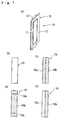
- Fig. 1 and Fig. 2 show a fuel cell A showing the first embodiment of the present invention.
- the fuel cell A showing the first embodiment comprises, as shown in Fig. 1 (a), a base material 10 of a carbonaceous porous body having electrical conductivity and has a unit cell (cell of fuel cell) 14 in which the respective layers (MEA) of electrode 11/electrolyte 12/electrode 13 are formed on the surface of the above base material 10.
- the carbonaceous porous body which is the base material 10 in the present embodiment has electrical conductivity and functions (hereinafter referred to merely as "respective characteristics") as an impregnating medium for liquid fuel and air and a cell supporter, and the material thereof shall not specifically be restricted as long as it has the above characteristics. It includes, for example, amorphous carbon, a composite of amorphous carbon and carbon material powder, an isotropic high density carbon molded article, a carbon fiber papermaking molded article and an activated carbon molded article, and the carbonaceous porous body is preferably constituted from amorphous carbon or a composite of amorphous carbon and carbon material powder from the viewpoints of moldability, a cost and easiness in obtaining the desired physical properties.
- Amorphous carbon is obtained by baking at least one raw material selected from materials showing a carbonization yield of 5 % or more by baking, for example, thermoplastic resins such as polyvinyl chloride, chlorinated vinyl chloride resins, polyacrylonitrile, polyvinyl alcohol and vinyl chloride-vinyl acetate copolymers, thermosetting resins such as phenol resins, furan resins, imide resins and epoxy resins, and natural high molecular substances such as cellulose and gum arabic.
- thermoplastic resins such as polyvinyl chloride, chlorinated vinyl chloride resins, polyacrylonitrile, polyvinyl alcohol and vinyl chloride-vinyl acetate copolymers
- thermosetting resins such as phenol resins, furan resins, imide resins and epoxy resins
- natural high molecular substances such as cellulose and gum arabic.
- the carbon material powder includes, for example, at least one selected from the group consisting of graphite, pitch obtained by subjecting further a tar-like substance to dry distillation, carbon fibers, carbon nanotubes and mesocarbon microbeads.
- the composite of the amorphous carbon and the carbon material powder described above is obtained by mixing 50 to 100 % by weight of an amorphous carbon raw material having a controlled particle diameter with 0 to 50 % by weight of carbon material powder based on the total amount and carbonizing the mixture at 700°C or higher in an inert atmosphere.
- the carbonaceous porous body of the base material 10 has preferably an average pore diameter of 1 to 100 ⁇ m and a porosity of 10 to 85 % and has preferably a liquid-impregnating property by a capillary phenomenon (function for impregnating liquid fuel) and strength sufficient for holding a self form.
- the carbonaceous porous body has more preferably an average pore diameter of 5 to 70 ⁇ m and a porosity of 20 to 70 % and particularly has preferably a liquid-impregnating property by a capillary phenomenon.
- the carbonaceous porous body is allowed to have an average pore diameter of 20 ⁇ m and a porosity of 55 % and have a liquid-impregnating property by a capillary phenomenon and strength sufficient for holding a self form.
- the base material obtained may further be subjected to treatment such as air oxidation and electrochemical oxidation.
- the carbonaceous porous body having the intended continuous pores can be produced by putting the heat-fusible resin particles described above in a mold having an optional form, fusing them with heating and baking them in an inert atmosphere. Further, the carbonaceous porous body having the intended continuous pores can be produced as well by mixing a resin which is a binder with graphite and the like which is carbon material powder, crushing and pelletizing the mixture, putting it in a mold having an optional form and press-molding and baking it in an inert atmosphere.
- the carbonaceous porous body of the base material 10 in the present embodiment assumes, as shown in Fig. 1 (a) and (b), a tabular form and has the respective characteristics described above in the whole.
- the base material 10 may have electrical conductivity at least in a part, and/or at least a part thereof may comprise a carbonaceous porous body.
- a part of the base material 10 may be, as shown in Fig. 1 (c), a non-conductive porous body 10a, and the other part thereof may be a conductive porous body 10b.
- MEA is formed on the surface of the conductive porous body 10b.
- an upper part and a lower part of the base material 10 may be, as shown in Fig. 1 (d), the non-conductive porous body 10a, and the other part thereof may be the conductive porous body 10b.
- MEA is formed on the surface of the conductive porous body 10b.
- a part of the base material 10 may be, as shown in Fig. 1 (e), a conductive or non-conductive non-porous body 10c, and the other part thereof may be the conductive porous body 10b.
- MEA is formed on the surface of the conductive porous body 10b.
- the electrode 11 is a fuel electrode prepared by coating a platinum-ruthenium (Pt-Ru) catalyst, an iridium-ruthenium (Ir-Ru) catalyst or a platinum-tin (Pt-Sn) catalyst on one outside surface of the base material 10.
- Pt-Ru platinum-ruthenium
- Ir-Ru iridium-ruthenium
- Pt-Sn platinum-tin
- an ion exchange membrane having a proton conductivity or a hydroxy ion conductivity for example, a fluorine base ion exchange membrane using Nafion 112 and Nafion 117 (all manufactured by Du Pont Co., Ltd.), and in addition thereto, capable of being used as well are materials which are excellent in heat resistance and inhibition in methanol crossover, for example, a composite membrane comprising an inorganic compound as a proton conductive material and a polymer as a membrane material, to be specific, a composite membrane using zeolite as the inorganic compound and a styrene-butadiene base rubber as the polymer, and a hydrocarbon base graft membrane.
- a fluorine base ion exchange membrane using Nafion 112 and Nafion 117 all manufactured by Du Pont Co., Ltd.
- materials which are excellent in heat resistance and inhibition in methanol crossover for example, a composite membrane comprising an inorganic compound as a proton conductive material and a poly
- the electrode 13 is an air electrode prepared by carrying platinum (Pt), palladium (Pd), rhodium (Rh) or the like on a sheet-like carbon porous body comprising a porous structure such as carbon paper by coating.
- the unit cell 14 of the present embodiment can be formed by interposing the electrolyte membrane 12 between the fuel electrode 11 prepared by coating a Pt-Ru/C catalyst on the surface of the base material 10 having the respective characteristics described above and the air electrode 13 prepared by coating a Pt/C catalyst on the sheet-like carbon porous body and hot-pressing them.
- the unit cell 14 thus obtained stores liquid fuel and is held by a holder member 20 for holding the above unit cell.
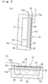
- the holder member 20 has, as shown in Fig. 2 (a) and (b), a cross-section of a concave form in which one side is opened, and the inside thereof is a liquid fuel-storing part 21 for storing liquid fuel 30.
- the unit cell 14 is fitted to the inside of the holder member 20 by fitting members 22, 22 so that the air electrode 13 is situated at an outside surface (atmosphere).
- a material for the above holder member 20 shall not specifically be restricted as long as it has storage stability and durability to the liquid fuel stored therein, and it includes, for example, metals such as stainless steel and synthetic resins such as polypropylene, polyethylene and polyethylene terephthalate (PET).
- An indicated symbol 23 is a fuel-feeding port having a cover, and indicated symbols 11a, 13a each are a fuel electrode terminal and an air electrode terminal.
- the liquid fuel 30 stored in the liquid fuel-storing part 21 described above includes a methanol solution comprising methanol and water, but the liquid fuel shall not specifically be restricted as long as hydrogen fed as fuel can be decomposed to hydrogen ion (H + ) and electron (e - ) at the fuel electrode 11, and capable of being used as well are, though depending on the structure of the fuel electrode 11, for example, liquid fuels each having a hydrogen source such as dimethyl ether (DME, CH 3 OCH 3 ), an ethanol solution, formic acid, hydrazine and an ammonia solution.
- concentrations of the respective liquid fuels such as DME, methanol and ethanol are suitably set up.
- the methanol solution is preferred from the viewpoints of a cost, supply capability and high reactivity, and a concentration thereof is preferably 0.5 to 20 M (mol/L), more preferably 5 to 18 M.
- a methanol concentration of 1 to 3 M was usually regarded as an optimum value, and the performance was lowered at a higher concentration thereof due to crossover.
- use of the base material having the respective characteristics described above makes it possible to use as well a methanol solution having a high concentration of 5 M or more, particularly 10 M or more, which has not been used.
- the fuel cell A of the present embodiment assumes a structure in which the base material 10 comprises the carbonaceous porous body having electrical conductivity and in which the unit cell 14 in which the respective layers of electrode 11/electrolyte 12/electrode 13 are formed on the surface of the base material 10 is installed in the holder member 20 to impregnate the base material 10 with the liquid fuel 30 and further the electrode 13 formed on the outside surface of the base material 10 is exposed to air.
- the base material 10 described above has functions as an electrode ⁇ collector, an impregnating medium for liquid fuel and air and a cell supporter in common, and the liquid fuel 30 in the fuel-storing part 21 is introduced into the cell 14 by an impregnating action to generate power.
- the base material 10 has the characteristic described above, that is, electrical conductivity and functions as an impregnating medium for liquid fuel and air and a cell supporter, the liquid fuel does not leak to the outside, and when the fuel cell A assumes vertical configuration [Fig. 2 (a)] or horizontal configuration [Fig. 2 (b)], the liquid fuel can stably and continuously be fed directly from the fuel-storing part 21 to the unit cell 14 without stopping.
- the base material 10 of the carbonaceous porous body having electrical conductivity is allowed to have functions as an electrode ⁇ collector, an impregnating medium for liquid fuel and air and a cell supporter in common without using auxiliary devices such as a pump, a blower, a fuel vaporizer and a condenser, whereby a separator can be unnecessary. Accordingly, a structure in which the liquid fuel can smoothly be fed as it is without vaporizing is assumed by making use of the above unneeded space as a field for convecting and diffusing air or liquid fuel, so that the fuel cell can be reduced in a size.
- supplementing of the liquid fuel from the fuel-feeding port 23 makes it possible to readily supplement the fuel and stably feed the liquid fuel.
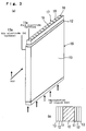
- Fig. 3 (a) and (b) show another embodiment of the cell 14 shown in Fig. 2 and are a perspective drawing and a partial cross-sectional drawing showing an embodiment in which the cell is turned into a cartridge form.
- the same symbols shall be shown in the case of the same structure as that of the embodiment described above, and the explanations thereof shall be omitted (the same shall apply to embodiments described below).
- Fig. 3 shows an embodiment in which liquid fuel (fuel solution) is impregnated from a lower part to an upper part.
- the above cell 15 of the fuel cell comprises, as shown in Fig. 3 (a) and (b), a base material 10 of a tabular carbonaceous porous body having the respective characteristics described above and has the respective layers (MEA) of electrode 11/electrolyte 12/electrode 13 formed on the surfaces (both surfaces) of the base material 10.
- An air vent member 17 having air and liquid holes 16, 16--- for degassing and accelerating impregnation of liquid fuel is fitted on the upper surface of the base material 10.
- the air and liquid holes may be packed with a water-absorbing material having a liquid-impregnating characteristic in order to accelerate impregnation of the liquid fuel.
- the water-absorbing material includes, for example, porous bodies having capillary force which are constituted from felt, sponge and sintered bodies such as resin particle-sintered bodies and resin fiber-sintered bodies and fiber bundles comprising one kind or a combination of two kinds selected from the group consisting of natural fibers, animal hair fibers, a polyacetal base resin, an acryl base resin, a polyester base resin, a polyamide base resin, a polyurethane base resin, a polyolefin base resin, a polyvinyl base resin, a polycarbonate base resin, a polyether base resin and a polyphenylene base resin.
- porous bodies having capillary force which are constituted from felt, sponge and sintered bodies such as resin particle-sintered bodies and resin fiber-sintered bodies and fiber bundles comprising one kind or a combination of two kinds selected from the group consisting of natural fibers, animal hair fibers, a polyacetal base resin, an acryl base resin, a polyester base resin, a polyamide base resin,
- the cell 15 which is turned into a cartridge form makes it possible to raise an efficiency of joining work and electrical connection in the cell 15 and to improve the performances of the fuel cell due to increase in a convecting and diffusing speed of air or the liquid fuel brought about by using a space between the cells.
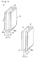
- Fig. 4 (a) is a perspective drawing showing an embodiment in which two cells of the fuel cell are constituted into one unit, and (b) is a perspective drawing showing a structure in which a partition wall for controlling absorption of the liquid fuel and diffusion of air is provided at an opposite side having no electrode layer in the cell.
- the cells 15, 15 in which a cell layer (electrode/electrolyte/electrode) is formed on one outside surface of the tabular carbonaceous porous body having the respective characteristics described above are disposed back to back at a prescribed interval to form a gap part 18 for allowing liquid fuel or air to flow and diffuse between the above cells 15, 15.
- the cells 15, 15 are electrically connected in a serial or parallel manner.
- the gap part 18 makes it possible to improve the performances of the cell due to increase in a convecting and diffusing speed of air or the liquid fuel.
- the gap part 18 may be packed with the water-absorbing material described above having a liquid-impregnating characteristic in order to accelerate impregnation of the liquid fuel.
- one unit is constituted in the form described above, and it is used alone, or two or more units which are electrically connected in a serial or parallel manner are used.
- the partition wall 19 is provided at a prescribed interval so that the gap part 18 having the same function as described above is formed at an opposite side having no electrode layer in the cell 15.
- the above partition wall 19 shall not specifically be restricted as long as it can cut off fuel or air, and it can be constituted from, for example, a plastic plate, a metal plate, a glass plate and a ceramic plate.
- Fig. 5 is a perspective drawing showing a structure in the case where the cells 15, 15 of the fuel cell turned into a cartridge form in Fig. 3 are serially connected
- Fig. 6 is a perspective drawing showing a structure in the case where the cells 15, 15 of the fuel cell turned into a cartridge form in Fig. 3 are parallel connected.
- the fuel cell may have a structure in which a lot of the cells 15, 15--- turned into a cartridge form in Fig. 3 are used to combine serial connection shown in Fig. 5 with parallel connection shown in Fig. 6.
- Fig. 7 is a perspective drawing showing a structure in the case where five cells 15, 15--- turned into a cartridge form in Fig. 3 are joined and serially connected.
- the cells 15, 15--- are preferably fitted so that intervals between the respective cells are equal via spacers, or they are preferably fitted at an equal interval to a holder member which stores the liquid fuel and holds the cells 15, 15---.
- Equalizing the intervals between the respective cells uniformizes flow and a concentration of air or fuel which convects and diffuses between the cells to uniformize the outputs of the respective cells, whereby stabilization in an output of the cell can be exhibited.
- the air may suitably be forcibly convected by means of a small-sized fan in order to obtain a high output by renewal of the air.
- a thickness of the base material 10 and an interval between the respective cells or between the cell and the partition wall body are varied depending on uses of the fuel cell, a size and a form of the cell 15, a liquid-absorbing performance of the base material 10 and liquid fuel used.
- H is preferably 1 to 20 mm
- K is preferably 1 to 20 mm, wherein H is a thickness of the base material, and K is an interval between the respective cells or the cell and the partition wall body.
- a width (W) of the base material (including the air vent member) 10 is varied depending on uses of the fuel cell, a size and a form of the cell 15, a liquid-absorbing performance of the base material 10 and liquid fuel used. It is preferably 1 to 500 mm, and the height (T) is preferably 5 to 300 mm.
- the thickness H of the base material 10 is 2 mm, and the interval K is 2 mm; the height T of the base material (including the air vent member) 10 is 50 mm, and the width W thereof is 50 mm.
- Fig. 8 (a) to (c) are schematic drawings showing a structure in which the cells of the embodiment shown in Fig. 7 are fitted to a holder member.
- the fuel cell B has a structure in which a carbonaceous porous body in the respective cells 15 is impregnated with the liquid fuel 30 and in which an electrode surface formed on the outside surface is exposed to air, and as shown in Fig. 8 (a) to (c), if a longitudinal direction of the respective cells is turned horizontal, vertical or oblique, the respective cells can be impregnated with the liquid fuel 30 from an upper, lower or lateral impregnating direction. Accordingly, the liquid fuel can stably and continuously be fed directly from the liquid fuel tank 31 to the respective cells 15 without stopping, and the liquid fuel is introduced into the respective cells 15 to generate power.
- a fuel cell C shown in Fig. 9 five cells of the cells 15, 15--- turned into a cartridge form shown in Fig. 3 are disposed in the inside of a liquid fuel tank 33 for storing liquid fuel 30 and fitted to the respective fitting parts in air chambers 34, 35 fitted to the upper and lower parts of the above tank 33, and intervals between the respective cells described above are set to an equal interval.
- the fuel cell C has a structure in which air is diffused or convected to the base material of the respective cells 15, 15--- by means of the air chambers 34, 35 described above and in which an electrode surface formed on the outside surface of the base material is exposed to the liquid fuel 30.
- the liquid fuel can stably and continuously be fed directly from the liquid fuel tank 33 to the respective cells 15 without stopping, and the liquid fuel is introduced into the respective cells 15 to generate power.
- Fig. 10 shows the embodiment of a fuel cell for a high output (for example, several ten to 100 W).
- this fuel cell D comprises in order from a lower part, a fuel tank 40 for storing liquid fuel 30, an accommodating part 41 for accommodating a lot of cells 15, 15--- turned into a cartridge form and a holder 42 having an exhaust port for gas produced in the liquid fuel.
- the cells 15, 15--- described above are fitted to the respective fitting parts of the fuel tank 40 for storing the liquid fuel 30 and the holder 42, and intervals between the respective cells are set to an equal interval.
- the peripheral surface of the accomodating part 41 is constituted from an air flow member 43 through which air is easy to pass, for example, a net, a slit and the like.
- the respective cells 15, 15--- are serially connected, and an indicated symbol 44 is a terminal of an electric source.
- the fuel cell D has a structure in which a carbonaceous porous body in the respective cells 15 is impregnated with the liquid fuel 30 and in which an electrode surface formed on the outside surface is exposed to air.
- the liquid fuel can stably and continuously be fed directly from the liquid fuel tank 40 to the respective cells 15 without stopping, and the liquid fuel is introduced into the respective cells 15 to generate power. Air may be blown by means of a fan from the viewpoint of further increase in the output.
- Fig. 11 (a) to (c) are schematic drawings showing a fuel cell of an embodiment which is accommodated in small-sized appliances such as writing instruments, celluar phones and note type personal computers, and it is a fuel cell E in which a cylindrical cell of the fuel cell is used.
- the above fuel cell E is different from the fuel cell D described above in that it is cylindrical in an appearance form. It comprises in order from a lower part, as shown in Fig. 11 (a), a fuel tank 45 for storing liquid fuel 30, an accommodating part 46 for accommodating a lot (6 cells in the present embodiment) of cylindrical cells 16, 16--- and a holder 47 having an exhaust port for gas produced in the liquid fuel.
- the cells 16, 16--- are fitted to the respective fitting parts of the fuel tank 45 for storing the liquid fuel 30 and the holder 47, and intervals between the respective cells are set to an equal interval.
- the peripheral surface of the accommodating part 46 is constituted from an air flow member 48 through which air is easy to pass, for example, a net, a slit and the like.
- the respective cells 16, 16--- are electrically connected in a serial or parallel manner, whereby they can readily be stacked.
- An indicated symbol 49 is a terminal of an electric source.
- the respective cells 16, 16--- have a structure in which a through hole 16a for degassing and accelerating impregnation of the liquid fuel is formed in a central part and in which the respective layers of electrode 11/electrolyte 12/electrode 13 are formed on the outside surface of a cylindrical porous carbon base material 10.
- the fuel cell E has a structure in which a carbonaceous porous body in the respective cells 16 is impregnated with the liquid fuel 30 and in which an electrode surface formed on the outside surface is exposed to air.
- a cylindrical solid space can effectively used, and a separator is unneeded.
- a space in which an air electrode on the outside surface can sufficiently be brought into contact with air can be secured.
- the liquid fuel can stably and continuously be fed directly from the liquid fuel tank 44 to the respective cells 16 without stopping, and the liquid fuel is introduced into the respective cylindrical cells 16 to generate power.
- the fuel cells of the present invention have the structures described above and exhibits the respective actions and effects, but the present invention shall not be restricted to the embodiments described above and can be carried out in various embodiments as long as the scope of the present invention is not changed.
- the carbonaceous porous body which is the base material described above has a tabular or cylindrical form, but it may have a prismatic, circular cylindrical, square cylindrical or corrugated sheet form.
- a part of the carbonaceous porous body may be non-conductive and non-porous.
- a carbonaceous porous body having the following structure produced by the following production process was used for a base material.
- Chlorinated vinyl chloride resin powder 97 parts prepared by classifying chlorinated vinyl chloride resin powder (T-741, manufactured by Nippon Carbide Industries Co., Inc.) in a range of 50 to 300 ⁇ m was mixed well with natural scaly graphite (average particle diameter: 5 ⁇ m, manufactured by Nippon Graphite Industries, Ltd.) by means of a Henschel mixer, and the mixture was put into a mold having a length of 100 mm, a width of 100 mm and a depth of 5 mm. Then, it was baked up to 1000°C under an inert atmosphere, whereby the powder particles were fused to obtain a carbonaceous porous body (average particle diameter: 20 ⁇ m, porosity: 55 %) having continuous pores.
- the carbonaceous porous body thus obtained was processed to obtain a carbonaceous porous body having a width of 25 mm, a length of 65 mm and a thickness of 2 mm.
- the resulting carbonaceous porous body described above having a width of 25 mm, a length of 65 mm and a thickness of 2 mm was used as a base material 10.
- a slurry comprising a mixture of catalyst powder obtained by carrying platinum fine particles on a carbon fine particle carrier in a proportion of 50 wt %, water, glycerol and a solution of Nafion in an alcohol aqueous solution was coated on the surface of carbon paper subjected to water repellent treatment in a thickness of about 50 ⁇ m and dried to form a porous membrane. This was cut to a width of 25 mm and a length of 65 mm to prepare an air electrode 13.
- a Nafion 112 electrolyte membrane having a thickness of 50 ⁇ m was cut to a width of 25 mm and a length of 100 mm to prepare an electrolyte membrane 12.
- a small amount of the 5 wt % solution of Nafion 117 in alcohol was coated on the surface of the fuel electrode layer and the air electrode layer and dried, and then the electrolyte membrane was interposed between the fuel electrode layer and the air electrode layer so that the respective electrode layers were superposed each other, and the laminate was pressed at 130°C and about 80 kgf/cm 2 and held for 3 minutes to stick them, whereby a cell (MEA) was prepared.
- MEA cell
- a power generation test (current-voltage curve) was carried out respectively for the case where the above fuel cell assumed a vertical configuration [refer to Fig. 2 (a)] in which only a lower part of the base material of the carbonaceous porous body is brought into contact with the methanol aqueous solution to self-impregnate the base material with the methanol aqueous solution and the case where the fuel cell assumed a horizontal configuration [refer to Fig. 2 (b)] to impregnate the base material with the methanol aqueous solution.
- the air electrode was exposed to air at room temperature (25°C) and an atmospheric pressure without flow.
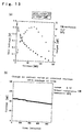
- Fig. 13 (a) shows a current-voltage curve in the case where a methanol concentration is 10 M, and (b) shows the result of continuous power generation at a fixed voltage (0.1 V). It has become clear that almost the same output as the case of 2 M is obtained as well in the case of 10 M and that the fuel cells work so well that the same power generation characteristic is obtained in a wide concentration range. Further, it has become clear that the voltage does not fall to a large extent in the case of continuous power generation for 8 hours or longer to stably output current and that the fuel cells can stably work well.
- the power generation test (current-voltage curve) was carried out for the fuel cells thus obtained in the same manner as described above.
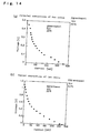
- Fig. 14 (a) shows a current-voltage curve in the case of parallel connection, and (b) shows a current-voltage curve in the case of serial connection. A current value which is almost twice as large as that of the unit cell is obtained in the parallel connection, and voltage which is as almost twice as large as that of the unit cell is obtained in the serial connection. It has become clear that the fuel cells work well in the case of the connected assembly too.
- a carbonaceous porous body having the following structure produced by the following production process was used for a base material.
- Dry-distilled pitch (KH-IP, manufactured by Kureha Chemical Industry Co., Ltd.) 15 parts, a furan resin (VF303, manufactured by Hitachi Chemical Co., Ltd.) 35 parts, polymethyl methacrylate (average particle diameter: 60 ⁇ m, manufactured by Sekisui Plastics Co., Ltd.) 35 parts and natural scaly graphite (average particle diameter: 5 ⁇ m, manufactured by Nippon Graphite Industries, Ltd.) 15 parts were classified, mixed and kneaded, and thereafter the mixture was crushed, classified and then put into a mold having a length of 100 mm, a width of 100 mm and a depth of 5 mm. Then, it was subjected to compression molding to obtain a carbonaceous porous body (average particle diameter: 60 ⁇ m, porosity: 60 %) having continuous pores.
- the carbonaceous porous body thus obtained was processed to obtain a carbonaceous porous body having a width of 25 mm, a length of 65 mm and a thickness of 2 mm.
- the respective cells (MEA) were prepared in the same manner as that of the cells (MEA) prepared in Example 1 described above, provided that two kinds of Nafion 112 and 117 membranes having a thickness of 50 ⁇ m were used for the electrolyte membrane 12.
- a power generation test (current density-voltage curve) was carried out for the case where the above fuel cell assumed a horizontal configuration [Fig. 2 (b)] to impregnate the base material with the methanol aqueous solution.
- the air electrode was exposed to air at room temperature (15 to 18°C, 18°C to 20°C) and an atmospheric pressure without flow.
- the optimum value was usually shown at a methanol concentration of 1 to 3 M, and the performance was reduced at a higher concentration due to crossover of methanol.
- use of the base material having the characteristics described above makes it possible to make use of a methanol solution having a high concentration. As a result, an energy density of fuel per volume is raised, and therefore it is most suited for further reduction in a size of the appliances.
Landscapes
- Chemical & Material Sciences (AREA)
- Chemical Kinetics & Catalysis (AREA)
- Electrochemistry (AREA)
- General Chemical & Material Sciences (AREA)
- Life Sciences & Earth Sciences (AREA)
- Engineering & Computer Science (AREA)
- Manufacturing & Machinery (AREA)
- Sustainable Development (AREA)
- Sustainable Energy (AREA)
- Fuel Cell (AREA)
- Inert Electrodes (AREA)
Applications Claiming Priority (4)
| Application Number | Priority Date | Filing Date | Title |
|---|---|---|---|
| JP2004028326 | 2004-02-04 | ||
| JP2004028326 | 2004-02-04 | ||
| JP2004126978 | 2004-04-22 | ||
| JP2004126978A JP4596814B2 (ja) | 2004-02-04 | 2004-04-22 | 燃料電池 |
Publications (2)
| Publication Number | Publication Date |
|---|---|
| EP1562246A2 true EP1562246A2 (de) | 2005-08-10 |
| EP1562246A3 EP1562246A3 (de) | 2006-06-28 |
Family
ID=34680681
Family Applications (1)
| Application Number | Title | Priority Date | Filing Date |
|---|---|---|---|
| EP05001786A Withdrawn EP1562246A3 (de) | 2004-02-04 | 2005-01-28 | Flüssigbrennstoffzelle |
Country Status (3)
| Country | Link |
|---|---|
| US (1) | US20050170237A1 (de) |
| EP (1) | EP1562246A3 (de) |
| JP (1) | JP4596814B2 (de) |
Cited By (3)
| Publication number | Priority date | Publication date | Assignee | Title |
|---|---|---|---|---|
| DE102006030236A1 (de) * | 2006-06-30 | 2008-01-03 | Fraunhofer-Gesellschaft zur Förderung der angewandten Forschung e.V. | Direktoxidationsbrennstoffzelle für den konvektionsfreien Transport des Brennstoffs und Verfahren zum Betreiben der Brennstoffzelle |
| EP2063477A4 (de) * | 2006-08-25 | 2010-10-06 | Toshiba Kk | Brennstoffzelle |
| EP2600451A3 (de) * | 2011-11-29 | 2015-02-11 | Samsung Electronics Co., Ltd | Elektrodenkatalysator für eine Brennstoffzelle, Verfahren zu seiner Herstellung sowie Membranelektrodenanordnung und Brennstoffzelle mit dem Elektrodenkatalysator |
Families Citing this family (11)
| Publication number | Priority date | Publication date | Assignee | Title |
|---|---|---|---|---|
| US20050158609A1 (en) * | 2004-01-16 | 2005-07-21 | Gennadi Finkelshtain | Hydride-based fuel cell designed for the elimination of hydrogen formed therein |
| US20050260481A1 (en) * | 2004-05-20 | 2005-11-24 | Gennadi Finkelshtain | Disposable fuel cell with and without cartridge and method of making and using the fuel cell and cartridge |
| US20060057435A1 (en) * | 2004-09-15 | 2006-03-16 | Medis Technologies Ltd | Method and apparatus for preventing fuel decomposition in a direct liquid fuel cell |
| JP4715405B2 (ja) * | 2005-09-08 | 2011-07-06 | カシオ計算機株式会社 | 反応装置 |
| JP4939786B2 (ja) * | 2005-09-29 | 2012-05-30 | 株式会社東芝 | 燃料電池及び燃料電池システム |
| DE112007000759T5 (de) | 2006-03-27 | 2009-01-29 | Mitsubishi Pencil Co. Limited | Brennstoffzelle |
| US7704629B2 (en) * | 2007-01-22 | 2010-04-27 | Panasonic Corporation | Direct oxidation fuel cells with improved cathode gas diffusion media for low air stoichiometry operation |
| JP2008181753A (ja) * | 2007-01-24 | 2008-08-07 | Sharp Corp | 燃料電池用電極、膜電極接合体および燃料電池 |
| KR20080105255A (ko) * | 2007-05-30 | 2008-12-04 | 현대자동차주식회사 | 전기전도도가 향상된 5-레이어 mea 제조 방법 |
| JP7418165B2 (ja) | 2019-07-30 | 2024-01-19 | 三菱鉛筆株式会社 | 吸液体 |
| JP7606355B2 (ja) * | 2021-01-28 | 2024-12-25 | 日産自動車株式会社 | 発電体 |
Family Cites Families (17)
| Publication number | Priority date | Publication date | Assignee | Title |
|---|---|---|---|---|
| JPS5966066A (ja) * | 1982-10-06 | 1984-04-14 | Hitachi Ltd | 液体燃料電池 |
| JPS5983352A (ja) * | 1982-11-05 | 1984-05-14 | Nissan Motor Co Ltd | 燃料電池用電極の製造方法 |
| JP2939978B2 (ja) * | 1988-11-30 | 1999-08-25 | 松下電器産業株式会社 | アルコール燃料電池及びその作動方法 |
| US5364711A (en) * | 1992-04-01 | 1994-11-15 | Kabushiki Kaisha Toshiba | Fuel cell |
| JPH06188008A (ja) * | 1992-04-01 | 1994-07-08 | Toshiba Corp | 燃料電池 |
| US5589289A (en) * | 1995-09-27 | 1996-12-31 | Motorola, Inc. | Carbon electrode materials for electrochemical cells and method of making same |
| DE69608770T2 (de) * | 1995-12-06 | 2000-10-12 | Honda Giken Kogyo K.K., Tokio/Tokyo | Direkt Methanol-Brennstoffzelle |
| US6447941B1 (en) * | 1998-09-30 | 2002-09-10 | Kabushiki Kaisha Toshiba | Fuel cell |
| US6492052B2 (en) * | 1999-12-17 | 2002-12-10 | The Regents Of The University Of California | Air breathing direct methanol fuel cell |
| JP2003529195A (ja) * | 2000-03-28 | 2003-09-30 | マンハッタン・サイエンティフィックス・インコーポレイテッド | 燃料電池装置とその動作方法 |
| EP1244165A3 (de) * | 2001-03-19 | 2006-03-29 | Ube Industries, Ltd. | Elektrodenbasismaterial für Brennstoffzelle |
| JP2002343378A (ja) * | 2001-05-18 | 2002-11-29 | Hitachi Ltd | 燃料電池,燃料電池発電装置及びそれを用いた機器 |
| JP2003068325A (ja) * | 2001-08-28 | 2003-03-07 | Sharp Corp | 燃料電池 |
| JP2003187810A (ja) * | 2001-12-13 | 2003-07-04 | Sony Corp | 発電体構造及びその製造方法 |
| KR100450820B1 (ko) * | 2002-04-23 | 2004-10-01 | 삼성에스디아이 주식회사 | 공기 호흡형 직접 메탄올 연료전지 셀팩 |
| JP3747888B2 (ja) * | 2002-06-24 | 2006-02-22 | 日本電気株式会社 | 燃料電池、燃料電池用電極およびそれらの製造方法 |
| US20040001991A1 (en) * | 2002-07-01 | 2004-01-01 | Kinkelaar Mark R. | Capillarity structures for water and/or fuel management in fuel cells |
-
2004
- 2004-04-22 JP JP2004126978A patent/JP4596814B2/ja not_active Expired - Fee Related
-
2005
- 2005-01-28 EP EP05001786A patent/EP1562246A3/de not_active Withdrawn
- 2005-02-02 US US11/047,567 patent/US20050170237A1/en not_active Abandoned
Cited By (3)
| Publication number | Priority date | Publication date | Assignee | Title |
|---|---|---|---|---|
| DE102006030236A1 (de) * | 2006-06-30 | 2008-01-03 | Fraunhofer-Gesellschaft zur Förderung der angewandten Forschung e.V. | Direktoxidationsbrennstoffzelle für den konvektionsfreien Transport des Brennstoffs und Verfahren zum Betreiben der Brennstoffzelle |
| EP2063477A4 (de) * | 2006-08-25 | 2010-10-06 | Toshiba Kk | Brennstoffzelle |
| EP2600451A3 (de) * | 2011-11-29 | 2015-02-11 | Samsung Electronics Co., Ltd | Elektrodenkatalysator für eine Brennstoffzelle, Verfahren zu seiner Herstellung sowie Membranelektrodenanordnung und Brennstoffzelle mit dem Elektrodenkatalysator |
Also Published As
| Publication number | Publication date |
|---|---|
| JP2005251715A (ja) | 2005-09-15 |
| JP4596814B2 (ja) | 2010-12-15 |
| EP1562246A3 (de) | 2006-06-28 |
| US20050170237A1 (en) | 2005-08-04 |
Similar Documents
| Publication | Publication Date | Title |
|---|---|---|
| AU2001242584B2 (en) | Mixed reactant fuel cells | |
| US6492052B2 (en) | Air breathing direct methanol fuel cell | |
| US7407721B2 (en) | Direct oxidation fuel cell operating with direct feed of concentrated fuel under passive water management | |
| US6458479B1 (en) | Air breathing direct methanol fuel cell | |
| US20040058203A1 (en) | Mixed reactant fuel cells | |
| EP1562246A2 (de) | Flüssigbrennstoffzelle | |
| JPWO2005112172A1 (ja) | 燃料電池 | |
| AU2001242590A1 (en) | Mixed reactant fuel cells with flow through porous electrodes | |
| US20080014491A1 (en) | Fuel cell | |
| US20090023046A1 (en) | Porous Transport Structures for Direct-Oxidation Fuel Cell System Operating with Concentrated Fuel | |
| CN100428550C (zh) | 燃料电池,燃料电池用氧化剂流场板 | |
| WO2008091330A2 (en) | Direct oxidation fuel cells with improved cathode gas diffusion media for low air stoichiometry operation | |
| US8153324B2 (en) | Controlled-release vapor fuel cell | |
| US9373851B2 (en) | Fuel cell | |
| JP5182559B2 (ja) | 固体高分子型燃料電池 | |
| US8278001B2 (en) | Low-porosity anode diffusion media for high concentration direct methanol fuel cells and method of making | |
| US6866952B2 (en) | Apparatus and method for controlling undesired water and fuel transport in a fuel cell | |
| JP4778659B2 (ja) | 燃料電池及びその発電方法 | |
| JP2007059234A (ja) | 直接液体型燃料電池 | |
| JP2007109639A (ja) | 直接液体型燃料電池 | |
| US20090269653A1 (en) | Fuel cell | |
| WO2007110941A1 (ja) | 燃料電池 | |
| JP4822695B2 (ja) | 燃料電池 | |
| US20090208783A1 (en) | Low porosity anode diffusion media for fuel cells | |
| Lam | Novel direct liquid fuel cell-membraneless architecture and simple power and fuel crossover control |
Legal Events
| Date | Code | Title | Description |
|---|---|---|---|
| PUAI | Public reference made under article 153(3) epc to a published international application that has entered the european phase |
Free format text: ORIGINAL CODE: 0009012 |
|
| 17P | Request for examination filed |
Effective date: 20050226 |
|
| AK | Designated contracting states |
Kind code of ref document: A2 Designated state(s): AT BE BG CH CY CZ DE DK EE ES FI FR GB GR HU IE IS IT LI LT LU MC NL PL PT RO SE SI SK TR |
|
| AX | Request for extension of the european patent |
Extension state: AL BA HR LV MK YU |
|
| PUAL | Search report despatched |
Free format text: ORIGINAL CODE: 0009013 |
|
| AK | Designated contracting states |
Kind code of ref document: A3 Designated state(s): AT BE BG CH CY CZ DE DK EE ES FI FR GB GR HU IE IS IT LI LT LU MC NL PL PT RO SE SI SK TR |
|
| AX | Request for extension of the european patent |
Extension state: AL BA HR LV MK YU |
|
| RIC1 | Information provided on ipc code assigned before grant |
Ipc: H01M 8/24 20060101ALI20060522BHEP Ipc: H01M 8/02 20060101ALI20060522BHEP Ipc: H01M 4/88 20060101ALI20060522BHEP Ipc: H01M 4/86 20060101ALI20060522BHEP Ipc: H01M 8/10 20060101AFI20050523BHEP |
|
| AKX | Designation fees paid |
Designated state(s): IT |
|
| REG | Reference to a national code |
Ref country code: DE Ref legal event code: 8566 |
|
| 17Q | First examination report despatched |
Effective date: 20070807 |
|
| STAA | Information on the status of an ep patent application or granted ep patent |
Free format text: STATUS: THE APPLICATION HAS BEEN WITHDRAWN |
|
| 18W | Application withdrawn |
Effective date: 20080710 |