EP1561883A1 - Tour d'éolienne, partie de paroi métallique préfabriquée pour utiliser dans un tel tour, et procédé de construction d'un tel tour - Google Patents
Tour d'éolienne, partie de paroi métallique préfabriquée pour utiliser dans un tel tour, et procédé de construction d'un tel tour Download PDFInfo
- Publication number
- EP1561883A1 EP1561883A1 EP05075067A EP05075067A EP1561883A1 EP 1561883 A1 EP1561883 A1 EP 1561883A1 EP 05075067 A EP05075067 A EP 05075067A EP 05075067 A EP05075067 A EP 05075067A EP 1561883 A1 EP1561883 A1 EP 1561883A1
- Authority
- EP
- European Patent Office
- Prior art keywords
- tower
- metal wall
- prefabricated metal
- wind turbine
- flange
- Prior art date
- Legal status (The legal status is an assumption and is not a legal conclusion. Google has not performed a legal analysis and makes no representation as to the accuracy of the status listed.)
- Granted
Links
Images


Classifications
-
- E—FIXED CONSTRUCTIONS
- E04—BUILDING
- E04H—BUILDINGS OR LIKE STRUCTURES FOR PARTICULAR PURPOSES; SWIMMING OR SPLASH BATHS OR POOLS; MASTS; FENCING; TENTS OR CANOPIES, IN GENERAL
- E04H12/00—Towers; Masts or poles; Chimney stacks; Water-towers; Methods of erecting such structures
- E04H12/02—Structures made of specified materials
- E04H12/08—Structures made of specified materials of metal
- E04H12/085—Details of flanges for tubular masts
-
- F—MECHANICAL ENGINEERING; LIGHTING; HEATING; WEAPONS; BLASTING
- F03—MACHINES OR ENGINES FOR LIQUIDS; WIND, SPRING, OR WEIGHT MOTORS; PRODUCING MECHANICAL POWER OR A REACTIVE PROPULSIVE THRUST, NOT OTHERWISE PROVIDED FOR
- F03D—WIND MOTORS
- F03D13/00—Assembly, mounting or commissioning of wind motors; Arrangements specially adapted for transporting wind motor components
- F03D13/10—Assembly of wind motors; Arrangements for erecting wind motors
-
- F—MECHANICAL ENGINEERING; LIGHTING; HEATING; WEAPONS; BLASTING
- F05—INDEXING SCHEMES RELATING TO ENGINES OR PUMPS IN VARIOUS SUBCLASSES OF CLASSES F01-F04
- F05B—INDEXING SCHEME RELATING TO WIND, SPRING, WEIGHT, INERTIA OR LIKE MOTORS, TO MACHINES OR ENGINES FOR LIQUIDS COVERED BY SUBCLASSES F03B, F03D AND F03G
- F05B2230/00—Manufacture
- F05B2230/60—Assembly methods
-
- F—MECHANICAL ENGINEERING; LIGHTING; HEATING; WEAPONS; BLASTING
- F05—INDEXING SCHEMES RELATING TO ENGINES OR PUMPS IN VARIOUS SUBCLASSES OF CLASSES F01-F04
- F05B—INDEXING SCHEME RELATING TO WIND, SPRING, WEIGHT, INERTIA OR LIKE MOTORS, TO MACHINES OR ENGINES FOR LIQUIDS COVERED BY SUBCLASSES F03B, F03D AND F03G
- F05B2240/00—Components
- F05B2240/90—Mounting on supporting structures or systems
- F05B2240/91—Mounting on supporting structures or systems on a stationary structure
- F05B2240/912—Mounting on supporting structures or systems on a stationary structure on a tower
-
- Y—GENERAL TAGGING OF NEW TECHNOLOGICAL DEVELOPMENTS; GENERAL TAGGING OF CROSS-SECTIONAL TECHNOLOGIES SPANNING OVER SEVERAL SECTIONS OF THE IPC; TECHNICAL SUBJECTS COVERED BY FORMER USPC CROSS-REFERENCE ART COLLECTIONS [XRACs] AND DIGESTS
- Y02—TECHNOLOGIES OR APPLICATIONS FOR MITIGATION OR ADAPTATION AGAINST CLIMATE CHANGE
- Y02E—REDUCTION OF GREENHOUSE GAS [GHG] EMISSIONS, RELATED TO ENERGY GENERATION, TRANSMISSION OR DISTRIBUTION
- Y02E10/00—Energy generation through renewable energy sources
- Y02E10/70—Wind energy
- Y02E10/72—Wind turbines with rotation axis in wind direction
-
- Y—GENERAL TAGGING OF NEW TECHNOLOGICAL DEVELOPMENTS; GENERAL TAGGING OF CROSS-SECTIONAL TECHNOLOGIES SPANNING OVER SEVERAL SECTIONS OF THE IPC; TECHNICAL SUBJECTS COVERED BY FORMER USPC CROSS-REFERENCE ART COLLECTIONS [XRACs] AND DIGESTS
- Y02—TECHNOLOGIES OR APPLICATIONS FOR MITIGATION OR ADAPTATION AGAINST CLIMATE CHANGE
- Y02E—REDUCTION OF GREENHOUSE GAS [GHG] EMISSIONS, RELATED TO ENERGY GENERATION, TRANSMISSION OR DISTRIBUTION
- Y02E10/00—Energy generation through renewable energy sources
- Y02E10/70—Wind energy
- Y02E10/728—Onshore wind turbines
-
- Y—GENERAL TAGGING OF NEW TECHNOLOGICAL DEVELOPMENTS; GENERAL TAGGING OF CROSS-SECTIONAL TECHNOLOGIES SPANNING OVER SEVERAL SECTIONS OF THE IPC; TECHNICAL SUBJECTS COVERED BY FORMER USPC CROSS-REFERENCE ART COLLECTIONS [XRACs] AND DIGESTS
- Y02—TECHNOLOGIES OR APPLICATIONS FOR MITIGATION OR ADAPTATION AGAINST CLIMATE CHANGE
- Y02P—CLIMATE CHANGE MITIGATION TECHNOLOGIES IN THE PRODUCTION OR PROCESSING OF GOODS
- Y02P70/00—Climate change mitigation technologies in the production process for final industrial or consumer products
- Y02P70/50—Manufacturing or production processes characterised by the final manufactured product
Definitions
- This invention relates to a tower for a wind turbine which has an exterior side and an interior side and which tower is at least partly composed of prefabricated metal wall parts.
- the invention also relates to a prefabricated metal wall part for use in a tower for a wind turbine.
- the invention further relates to a method for constructing a tower for a wind turbine which has an exterior side and an interior side and wherein the tower is at least partly composed of prefabricated metal wall parts.
- the forces exerted on the top of the tower by the rotor-turbine assembly determine the load, i.e. the bending moments at all essentially horizontal flange connections and welds.
- the ultimate strength is determined by the yield strength of the bolts and by the buckling strength of the tubular metal wall.
- the welds are critical. During service, it is very difficult to inspect the quality of a weld. Also, on-site repairs are awkward.
- Hybrid towers such as towers with concrete walls, poured between an inner and outer steel shell have also been proposed.
- the problem is to assure the quality of the wall, once it has been poured.
- tension means are required to keep the concrete wall under compressive forces.
- concrete towers are not an economical solution.
- a tower for a wind turbine wherein the tower has an exterior side and an interior side and wherein the tower is at least partly composed of prefabricated metal wall parts wherein each wall part comprises an essentially quadrangular portion having an outwardly facing surface in the direction of the exterior of the tower and an inwardly facing surface in the direction of the interior of the tower, said portion having a top edge, a bottom edge, a first side edge and a second side edge, wherein the first side edge is provided with a first flange along at least part of the length of the first side edge and wherein the second side edge is provided with a second flange along at least part of the length of the second side edge.
- the stiffness of the construction is increased by the presence of the flanges of the prefabricated metal wall parts, which act as a rib.
- the transport of complete tower sections is no longer required, thus solving the transport problem.
- the prefabricated metal wall parts are easy to transport with ordinary transport means such as trucks.
- the size of the tower at the foundation is no longer limited by the transport restrictions and a wider base can be used. It also allows construction of higher towers because the size of the base is no longer an issue. The wider base results in a lower local pressure on the foundation, thus enabling to use a simpler foundation.
- the tower is substantially composed of prefabricated metal wall parts.
- the tower according to this embodiment relies on prefabricated metal wall parts as the load bearing elements, and are readily distinguishable from concrete towers, where a wall part serves as a mould for the concrete to be poured in and where, after setting, the concrete serves as the main load bearing material. It should be noted that the tower according to the invention does not comprise concrete as a load bearing material at the location of the prefabricated metal wall parts.
- a tower according to the invention on top of a concrete foundation or base wherein the concrete base extends upwardly, the base forming the lower part of the tower, and a tower according to the invention forming the upper part of the tower.
- first flanges and the second flanges of the prefabricated metal wall parts extend towards the interior side of the tower. This enables to produce a tower where the rib, formed by the adjacent flanges, is located on the inside of the tower, leaving a smooth exterior appearance. A smooth exterior leads to a reduced impact of wind force on the tower and a smooth exterior is considered to be visually more attractive.
- the prefabricated metal wall parts having a height and a width, at least two of the prefabricated metal wall parts have a height which is about 2.5 times larger than the width of the bottom edge, preferably more than five times larger, more preferably more than 10 times larger.
- the height of the prefabricated metal wall parts is to be understood to be the distance between the bottom edge and the top edge of the prefabricated metal wall parts when present in the tower.
- the length direction is defined in the direction of the height of the tower.
- the tower comprises prefabricated metal wall parts which are considerably higher than wide, thus resulting in long side edges of the essentially quadrangular portion of the prefabricated metal wall parts and thereby enabling long flanges being provided at least partly on the side edge thereof. These long flanges enable a large stiffening potential of the tower.
- the first flange of a prefabricated metal wall part is attached to the second flange of an adjacent second prefabricated metal wall part by fastening means.
- the flanges are now fixedly connected, thereby increasing the stiffening potential because of the double thickness of the rib.
- Fastening means comprise for instance a weld or a rivet.
- the fastening means comprise nuts and bolts. This enables to fasten quickly the first and second flange of two adjacent panels to each other.
- the holes required for the bolts to be inserted into may already be present in the prefabricated metal wall parts or may be drilled at the site where the connection between the adjacent panels is made.
- the use of nuts and bolts also enables to temporarily undo the connection, for instance to remove a prefabricated metal wall part from the construction, or to replace a prefabricated metal wall part. It also allows easy on-site and/or off-site inspection.
- the essentially quadrangular portion of the prefabricated metal wall parts is preferably orthogonal or trapezial wherein the length of the first side edge is approximately equal to the length of the second side edge and wherein the bottom edge is longer than the top edge.
- the use of orthogonal prefabricated metal wall parts is called for
- trapezial prefabricated metal wall parts are called for.
- Conical towers enable to construct a tower with a large base and become slimmer with increasing height of the tower. Tapering can be over the entire height of the tower or over part of the length of the tower. The latter can also be achieved by using prefabricated metal wall parts to form essentially cylindrical tower sections and by using prefabricated metal wall parts to form essentially conical tower sections and combine these tower sections into one tower.
- Kinked prefabricated metal wall parts may be used in the upper levels of a conically tapered tower or tower section for a wind turbine wherein the lower levels are made using prefabricated metal wall parts with an essentially flat quadrangular portion, thus reducing the number of prefabricated metal wall parts required for a full ring.
- One prefabricated metal wall part with one kink in the essentially quadrangular portion in a given upper level ring will link up with two prefabricated metal wall parts which have an essentially flat quadrangular portion in the ring immediately below the upper level ring.
- the kinked prefabricated metal wall parts contains more kinks, it may link up with a corresponding number of prefabricated metal wall parts with an essentially flat quadrangular portion. It will be clear that kinked prefabricated metal wall parts in a lower level can also be combined with kinked prefabricated metal wall parts in the upper level.
- the tower has an essentially annular, preferably essentially circular horizontal cross-section.
- An essentially annular horizontal cross section is also obtained if a polygonal horizontal cross section is taken with a large number of facets such as a pentagon or hexagon.
- the essentially quadrangular portion of the prefabricated metal wall parts are curved with a radius corresponding to the radius of the tower at the position of the location of the prefabricated metal wall part. This allows constructing a tower with a smooth curvature, and in case the first and second flanges extend towards the interior side of the tower, the exterior of the tower will be smooth.
- the quadrangular portion of the first prefabricated metal wall parts is essentially flat. The use of an essentially flat quadrangular portion has the advantage that there is no need for a locally dependent curvature in the quadrangular portion and is therefore easier to produce. It is also more convenient during transport of the prefabricated metal wall parts.
- the essentially flat quadrangular prefabricated metal wall parts also comprises at least one kink essentially in the direction between the bottom edge and the top edge of the prefabricated metal wall part.
- the kink (or kinks) therefore runs in the direction of the height of the tower. With the kink (or kinks) a higher buckling stiffness of the prefabricated metal wall part is obtained. It may alo increases the number of facets of the polygonal thereby achieving a smoother exterior of the tower.
- the invention is also embodied in a tower for a wind turbine as described hereinabove wherein the first flange is provided with an additional first flange along at least part of the length of the first flange and/or wherein the second flange is provided with an additional second flange along at least part of the length of the second flange.
- This is advantageous for instance for a further increase in stiffening the tower, particularly when the first flange and second flange are both provided with an additional flange, wherein the first flange with its respective additional flange preferably essentially forms an L-shape and/or wherein the second flange with its respective additional flange preferably essentially forms an L-shape.
- these additional flanges on the first and/or second flanges may be used to attach objects thereto such as stairs, or internal floors.
- the invention is also embodied in a tower for a wind turbine as described hereinabove wherein the first and/or second flanges are at least partly folded back towards the inwardly facing surface of the essentially quadrangular portion of the prefabricated metal wall part, thereby effectively doubling the thickness of the flanges.
- This doubling of the flanges causes an additional stiffening of the construction. It will be clear to the skilled person that the flange could also be folded back twice or more contributing to the stiffening effect.
- the prefabricated metal wall parts are steel parts, preferably high strength steel parts, for instance having a yield strength of about 355 MPa or higher.
- the use of steel enables to use prefabricated metal wall parts of a small thickness, which reduces the weight of the tower.
- the use of high strength steel prefabricated metal wall parts enables a further reduction in weight of the tower. As a result, the foundation of the tower can be constructed more efficient.
- the first flange of a first prefabricated metal wall part is vertically staggeredly attached to the second flange of an adjacent second prefabricated metal wall part by fastening means.
- This application of prefabricated metal wall parts by a stretching bond type connection of the flanges of two adjacent prefabricated metal wall parts also requires the application of prefabricated metal wall parts of different lengths, at least in the first and last ring of the tower or tower section.
- the application of this staggered connection has the advantage over constructing the tower from rings of connected non-staggeredly connected prefabricated metal wall parts that the forces are lead through the construction without having to be led through horizontal flanges which connect the aforementioned rings.
- the overlap at the edges between the staggeredly connected prefabricated metal wall parts is between 1:2 and 1:4, preferably about 1:3, meaning that about 1 ⁇ 2 to 3 ⁇ 4, preferably about 2 / 3 of the respective side edges of adjacent prefabricated metal wall parts overlap.
- the circumference of the tower consists of n adjacently positioned prefabricated metal wall parts, wherein the angle between the first flange and the second flange is 360/ n .
- the prefabricated metal wall part for use in a tower for a wind turbine as described hereinabove is characterised in that the prefabricated metal wall part comprises an essentially quadrangular portion having an outwardly facing surface and an inwardly facing surface, said portion having a top edge, a bottom edge, a first side edge and a second side edge, wherein the first side edge is provided with a first flange along at least part of the length of the first side edge and wherein the second side edge is provided with a second flange along at least part of the length of the second side edge.
- a method for constructing a tower for a wind turbine as described hereinabove, wherein the tower is at least partly composed of prefabricated metal wall parts as described hereinabove.
- the absence of horizontal welds in the towers according to the invention eliminates a known source of fatigue failure, thereby allowing to relieve design restrictions for instance by allowing to use thinner gauge metal plate.
- the locations where a bottom edge of a first prefabricated metal wall part touches a top edge of a prefabricated metal wall part which is located immediately below the first prefabricated metal wall part can be sealed by using sealing means, for instance a sealant. This prevents the outside atmosphere to enter the structure and prevents corrosion.
- the locations where the first flange of a prefabricated metal wall part is connected to the second flange of the adjacent prefabricated metal wall part can, if so desired, also be sealed using sealing means, such as a sealant.
- the tower is provided with stiffening means, such as one or more preferably substantially horizontal stiffening rings. These stiffening means are preferably provided in the interior of the tower to absorb the horizontal forces exerted on the tower. These stiffening means may be provided at different heights of the tower.
- the prefabricated metal wall parts are connected to the ring, thereby obtaining an increased stiffness of the tower. Additional connecting struts may be used to connect the prefabricated metal wall parts to the ring.
- the stiffening means may also be formed by internal floors, or the stiffening means, such as a stiffening ring along internal circumference of the tower, may provide the base for the internal floor or floors. The stiffening means may also contribute to the even distribution of forces and loads over the entire circumference of the tower.
- the prefabricated metal wall parts can be produced for example from hot-rolled metal using commonly known technology.
- the hot-rolled metal may be plate material or coiled material. This material, after optional leveling can be cut to the desired dimensions and shape, and the flanges can be formed on the edges of the essentially quadrangular portion of the prefabricated metal wall parts using conventional bending techniques.
- the optional curvature of the essentially quadrangular portion of the prefabricated metal wall parts or the kink or kinks can likewise be easily introduced.
- the prefabricated metal wall parts may be coated prior to use in the tower e.g. with zinc and/or an organic coating to extend the service life and to reduce maintenance.
- the prefabricated metal wall parts may also comprise additional built-in functionality such as a door for entering the interior of the tower. Internal structures like stairs and floors can be easily installed.
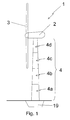
- FIG. 1 a schematic representation of a wind turbine 1 is shown.
- the wind turbine 1 comprises a generator 2, a rotor 3 and a tower 4 onto which the combination of the generator and the rotor is mounted.
- the tower 4 has an exterior surface which forms the outside of the tower 4 and an interior surface which forms the inside of the tower.
- the tower consists of four tower sections 4a-4d.
- the wind turbine is placed on a foundation 19.
- FIG 2 a tower 4 for a wind turbine according to the state of the art is shown.
- Tower segments 4a, 4b, 4c and 4d are mounted on top of each other. These tower segments are made off-site and connected through horizontal flanges and large bolts and nuts. These flanges are indicated schematically by the thick horizontal lines between the tower sections.
- the tower segments are made from curved plates which are welded together horizontally and vertically. These welds, indicated with the dashed lines, are known to be a possible source of fatigue failure, particularly the horizontal welds.
- a base of about 4.3 m and a top diameter of about 2.3 m is commonly used. The dimension of the base is limited by transport limitations.
- FIG 3a a tower 4 for a wind turbine according to the invention is shown, wherein the staggered prefabricated metal wall parts each stagger over about half the length of the neighbouring prefabricated metal wall part and figure 3b shows a tower wherein the staggered prefabricated metal wall parts each stagger over about a third of the length of the neighbouring prefabricated metal wall part.
- the base of the tower is about 6.5 m in diameter whereas the top of the tower has a diameter of about 2.3 m.
- the 6.5 m base diameter poses no transport problems because it can be transported to the building site in pieces.
- the increase in width of the base of the tower increases the stiffness of the tower. It also enables to construct higher towers width adequate stiffness to install high power wind turbines.
- Figure 4a shows an embodiment of a prefabricated metal wall part 5 according to the invention for use in a tower 4 for a wind turbine 1 as described hereinabove.
- the prefabricated metal wall part 5 is characterised in that the wall part comprises an essentially quadrangular portion 6 having an outwardly facing surface 7 facing the exterior of the tower and an inwardly facing surface 8 facing the interior of the tower, said portion having a top edge 9, a bottom edge 10, a first side edge 11 and a second side edge 12, wherein the first side edge 11 is provided with a first flange 13 along at least part of the length of the first side edge 11 and wherein the second side edge 12 is provided with a second flange 14 along at least part of the length of the second side edge 12.
- the first flange 13 is provided with an additional first flange 15 which essentially forms an L-shape with the first flange 13 and the second flange 14 is provided with an additional second flange 16 which essentially forms an L-shape with the second flange 14.
- the prefabricated metal wall parts are not drawn to scale.
- the cross section A-A is shown in figure 4b.
- Typical dimensions for such a prefabricated metal wall parts for the lower ring of a conical tower or tower segment would be a width at the top edge 9 of between about 0.60 and 1.00 m, for example about 0.86 m, a width at the bottom edge 10 of between about 1.30 and 0.70 m, for example about 1.04 m, a height of between about 10 and 20 meters, for example 20 meters, and a height of the extending first flange 13 and second flange 14 of between 0.10 and 0.20 m, for example about 0.15 m.
- a typical thickness of the prefabricated metal wall parts would be between 8 and 16 mm, for example about 12 mm.
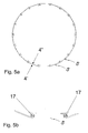
- FIG 5a a schematic cross section of the first ring of a tower for a wind turbine is shown.
- the essentially circular cross-section of the tower in this example is composed of eighteen prefabricated metal wall parts 5.
- the exterior of the tower is indicated by 4', the interior of the tower is indicated by 4".
- the first flange of each prefabricated metal wall parts is attached to the second flange of the adjacent prefabricated metal wall parts by bolts and nuts which are passed through holes in the first and second flange.
- Figure 5b shows a part of the first ring with the prefabricated metal wall parts 5 and the nuts and bolts 17.
- FIG 6 a schematic representation is shown of the L-shaped flange 18 which can be used to attach prefabricated metal wall parts of the first ring to the foundation 19 of the tower, or to the top ring on which the generator is attached.
- FIG 7 a schematic representation of part of the tower construction at the location of a stiffening ring is shown.
- the adjacent, staggeredly connected prefabricated metal wall parts are connected using an overlap at the edges (i.e. in a stretcher-bond type connection) of 1:3 and are also connected to the stiffening ring 20 using connecting struts 21.
- these connecting struts 21 are connected to the flanges 13, 14 (see figure 4) of the prefabricated metal wall parts on one side, and to the stiffening ring 20 on the other side.
- four prefabricated metal wall parts are shown which are indicated with A, B, C and D. The lower edge of part A and the upper edge of part B are adjacent.
- the first side edge of part A is adjacent and connected to the second side edge of part C by their adjacent flanges and fastening means (not shown).
- the connecting struts 21 extend above and below the stiffening ring 20, thereby enabling fixedly connecting the side edges of upper part A to the side edges of lower part B. Due to the 1:3 overlap in this example only about 1/3 of the circumference of the tower has a horizontal seam at or near the location of the stiffening ring. In the example of figure 8 the horizontal seam between part A and B is located near the stiffening ring 20.
- a tower for a wind turbine it is possible to first form a full ring of the tower by attaching at least two adjacent prefabricated metal wall parts along their adjacent flanges.
- This first full ring can be connected to an essentially flat and essentially horizontal foundation for the tower.
- the same result is obtained when starting with a first prefabricated metal wall part which is attached to the foundation after which a second prefabricated metal wall part is attached to the first prefabricated metal wall part and the foundation.
- the following full ring can be constructed upon the ring already present by first building the entire ring and subsequently lifting is on top of the ring already present, or by connecting prefabricated metal wall parts to the ring already present and to each other one by one, the former procedure requiring a larger capacity crane than the latter procedure. Rings are added to the rings already present until the desired height of the tower is obtained.
- the connection between the first full ring and the foundation may be achieved by using a flange that is connected to the foundation.
- the flanges may be simple L-shaped flanges.
- the flanges should have a corresponding curvature.
- a tower for a wind turbine it is possible to first form a full ring of the tower by attaching at least two adjacent prefabricated metal wall parts along their adjacent flanges vertically staggeredly.
- full length prefabricated metal wall parts are combined with prefabricated metal wall parts of half that length
- full length prefabricated metal wall parts are combined with prefabricated metal wall parts of 2/3 and 1/3 of that length (i.e. an overlap of 1:3).
- the remainder of the tower is constructed using essentially full length prefabricated metal wall parts.
- prefabricated metal wall parts of different lengths have to be used to make the top edge of the last ring level.
- prefabricated metal wall parts of non-full length elsewhere in the tower if so desired. This staggeredly attaching the prefabricated metal wall parts provides in a large stiffness of the tower, without introducing horizontal fully annular or circular flanges to connect tower sections.
- the tower When constructing a tower according to the invention, the tower may be constructed top down by starting to construct the top of the tower whilst being suspended onto a yoke construction, the yoke construction being provided with lifting means, such as a hydraulic jack.
- lifting means such as a hydraulic jack.
Priority Applications (2)
| Application Number | Priority Date | Filing Date | Title |
|---|---|---|---|
| EP05075067A EP1561883B1 (fr) | 2004-02-04 | 2005-01-14 | Tour d'éolienne, partie de paroi métallique préfabriquée pour utiliser dans un tel tour, et procédé de construction d'un tel tour |
| PL05075067T PL1561883T3 (pl) | 2004-02-04 | 2005-01-14 | Wieża dla turbiny wiatrowej, prefabrykowana część metalowej ściany do zastosowania w wieży dla turbiny wiatrowej i sposób budowy wieży dla turbiny wiatrowej |
Applications Claiming Priority (3)
| Application Number | Priority Date | Filing Date | Title |
|---|---|---|---|
| EP04075337 | 2004-02-04 | ||
| EP04075337 | 2004-02-04 | ||
| EP05075067A EP1561883B1 (fr) | 2004-02-04 | 2005-01-14 | Tour d'éolienne, partie de paroi métallique préfabriquée pour utiliser dans un tel tour, et procédé de construction d'un tel tour |
Publications (2)
| Publication Number | Publication Date |
|---|---|
| EP1561883A1 true EP1561883A1 (fr) | 2005-08-10 |
| EP1561883B1 EP1561883B1 (fr) | 2007-10-10 |
Family
ID=34833677
Family Applications (1)
| Application Number | Title | Priority Date | Filing Date |
|---|---|---|---|
| EP05075067A Not-in-force EP1561883B1 (fr) | 2004-02-04 | 2005-01-14 | Tour d'éolienne, partie de paroi métallique préfabriquée pour utiliser dans un tel tour, et procédé de construction d'un tel tour |
Country Status (17)
| Country | Link |
|---|---|
| US (1) | US20070294955A1 (fr) |
| EP (1) | EP1561883B1 (fr) |
| JP (1) | JP4708365B2 (fr) |
| CN (1) | CN100552174C (fr) |
| AT (1) | ATE375423T1 (fr) |
| AU (1) | AU2005211457B2 (fr) |
| BR (1) | BRPI0507467A (fr) |
| CA (1) | CA2554663C (fr) |
| DE (1) | DE602005002760T2 (fr) |
| DK (1) | DK1561883T3 (fr) |
| ES (1) | ES2296058T3 (fr) |
| NO (1) | NO20063907L (fr) |
| NZ (1) | NZ548883A (fr) |
| PL (1) | PL1561883T3 (fr) |
| PT (1) | PT1561883E (fr) |
| WO (1) | WO2005075763A2 (fr) |
| ZA (1) | ZA200606325B (fr) |
Cited By (22)
| Publication number | Priority date | Publication date | Assignee | Title |
|---|---|---|---|---|
| WO2007082531A1 (fr) * | 2006-01-17 | 2007-07-26 | Vestas Wind Systems A/S | Tour eolienne, turbine eolienne, elevateur de tour eolienne et procede d'assemblage de tour eolienne |
| WO2007095940A1 (fr) * | 2006-02-20 | 2007-08-30 | Vestas Wind Systems A/S | Tour de turbine eolienne, turbine eolienne et procede d'assemblage d'une tour de turbine eolienne |
| WO2008110309A2 (fr) | 2007-03-15 | 2008-09-18 | Mecal Applied Mechanics B.V. | Mât pour éolienne |
| EP2006471A1 (fr) * | 2007-06-20 | 2008-12-24 | Siemens Aktiengesellschaft | Tour d'éolienne et son procédé de construction |
| EP2047941A1 (fr) * | 2007-10-11 | 2009-04-15 | Siemens Aktiengesellschaft | Procédé pour le renforcement et/ou pour l'augmentation de la tolérance à la fatigue d'un assemblage soudé ; Elément pour tour d'éolienne ; Tour pour une éolienne et éolienne |
| ES2319709A1 (es) * | 2006-11-29 | 2009-05-11 | Prefabricaciones Y Contratas, S.A. | Estructura de soporte para dispositivos aerogeneradores. |
| WO2010049313A2 (fr) * | 2008-10-31 | 2010-05-06 | Vestas Wind Systems A/S | Procédé permettant d’ériger une tour |
| WO2010055535A1 (fr) * | 2008-11-17 | 2010-05-20 | Tecnopali Group S.P.A. | Tour tubulaire et procédure de construction |
| US7739843B2 (en) | 2007-08-03 | 2010-06-22 | Alejandro Cortina-Cordero | Pre-stressed concrete tower for wind power generators |
| DE102009014926A1 (de) * | 2009-03-25 | 2010-09-30 | Drössler GmbH Umwelttechnik | Turm |
| WO2011032559A3 (fr) * | 2009-09-15 | 2012-01-26 | Ib Andresen Industri A/S | Structure de construction tubulaire à segment de plate-forme articulé |
| CN102953323A (zh) * | 2012-12-04 | 2013-03-06 | 南京联众建设工程技术有限公司 | 一种拼接式波纹钢板承重柱 |
| EP2574772A1 (fr) | 2011-09-30 | 2013-04-03 | Siemens Aktiengesellschaft | Tour d'éolienne |
| EP2636899A1 (fr) | 2012-03-06 | 2013-09-11 | Siemens Aktiengesellschaft | Module de base de tour doté d'une bride de base segmentée |
| CN103899495A (zh) * | 2012-12-27 | 2014-07-02 | 北京万源工业有限公司 | 一种风力发电机组混合塔架 |
| US9175492B2 (en) | 2010-03-08 | 2015-11-03 | Acciona Windpower, S.A. | Wind generator tower and process for assembly thereof |
| WO2016091499A1 (fr) * | 2014-12-09 | 2016-06-16 | SIAG Industrie GmbH | Procédé pour fabriquer et ériger une construction de tour tubulaire |
| EP3196364A1 (fr) * | 2008-06-13 | 2017-07-26 | Tindall Corporation | Support de base pour générateurs d'éoliennes |
| EP2385245B1 (fr) | 2010-05-05 | 2017-09-13 | Siemens Aktiengesellschaft | Tour en acier pour éolienne |
| WO2019020464A1 (fr) * | 2017-07-26 | 2019-01-31 | Wobben Properties Gmbh | Partie de tour en acier pour éoliennes, pour une tour d'éolienne et procédé pour la produire |
| WO2019020463A1 (fr) * | 2017-07-26 | 2019-01-31 | Wobben Properties Gmbh | Segment annulaire de tour en acier pour éoliennes et procédé |
| US20200080335A1 (en) * | 2017-03-22 | 2020-03-12 | Wobben Properties Gmbh | Flange segment for a wind turbine, steel tower ring segment, and method |
Families Citing this family (58)
| Publication number | Priority date | Publication date | Assignee | Title |
|---|---|---|---|---|
| ES2326010B2 (es) * | 2006-08-16 | 2011-02-18 | Inneo21, S.L. | Estructura y procedimiento de montaje de torres de hormigon para turbinas eolicas. |
| DE102007018025A1 (de) | 2007-04-17 | 2008-10-23 | Nordex Energy Gmbh | Windenergieanlagenturm |
| WO2009031175A1 (fr) * | 2007-09-07 | 2009-03-12 | Smitt Technology S.R.L. | Tour, destinée notamment au support d'appareils de télécommunication |
| US8763313B2 (en) * | 2007-11-15 | 2014-07-01 | General Electric Company | Methods and systems for assembling a tower |
| US8590276B2 (en) * | 2008-02-06 | 2013-11-26 | Andresen Towers A/S | Tower element |
| ES2356679B1 (es) * | 2008-06-06 | 2011-11-28 | Manuel Torres Martinez | Torre para aerogenerador. |
| WO2010057187A2 (fr) * | 2008-11-17 | 2010-05-20 | Coben Larry F | Construction de tour appropriée pour les éoliennes ainsi que procédés de fabrication et d'installation |
| US20100132299A1 (en) * | 2008-12-02 | 2010-06-03 | General Electric Company | Wind turbine with improved tower and method of assembling same |
| CA2746880A1 (fr) * | 2008-12-15 | 2010-07-01 | Wind Tower Systems, Llc | Forme de structure pour elements de tour eolienne |
| US20100229473A1 (en) * | 2009-03-11 | 2010-09-16 | Thomas Industrial Rolls, Inc. | Pneumatic Tower Design |
| DE102009017593B4 (de) * | 2009-04-19 | 2011-01-27 | Timber Tower Gmbh | Turm für eine Windkraftanlage |
| EP2422084A2 (fr) * | 2009-04-19 | 2012-02-29 | Timbertower GmbH | Tour pour éolienne |
| DE102009017586A1 (de) * | 2009-04-19 | 2010-10-28 | Timber Tower Gmbh | Turm für eine Windkraftanlage |
| ES2435821T3 (es) * | 2009-05-19 | 2013-12-23 | Pacadar S.A. | Estructura de soporte para aerogeneradores |
| US20100132269A1 (en) * | 2009-06-15 | 2010-06-03 | General Electric Company | Rail-transportable wind turbine tower |
| US20100257739A1 (en) * | 2009-06-30 | 2010-10-14 | Sujith Sathian | Methods and flange for assembling towers |
| US7891939B1 (en) | 2009-09-05 | 2011-02-22 | Zuteck Michael D | Hybrid multi-element tapered rotating tower |
| US8061964B2 (en) | 2009-09-05 | 2011-11-22 | Michael Zuteck | Hybrid multi-element tapered rotating tower |
| DE102009048936B4 (de) * | 2009-09-11 | 2013-04-11 | Timber Tower Gmbh | Turm für eine Windkraftanlage und Verfahren zum Errichten eines Turmes für eine Windkraftanlage |
| US20100135821A1 (en) * | 2009-10-30 | 2010-06-03 | General Electric Company | Transportable wind turbine tower |
| IT1396433B1 (it) | 2009-11-16 | 2012-11-23 | Rolic Invest Sarl | Impianto eolico per la generazione di energia elettrica e metodo per realizzare un pilone del suddetto impianto eolico. |
| CN102834607B (zh) * | 2009-12-25 | 2016-07-06 | 苏州可汗极米科技有限公司 | 用于风力发电机的塔架 |
| US8720153B2 (en) | 2010-01-25 | 2014-05-13 | Keystone Tower Systems, Inc. | Tapered spiral welded structure |
| US10189064B2 (en) | 2010-01-25 | 2019-01-29 | Keystone Tower Systems, Inc. | Control system and method for tapered structure construction |
| US20130000241A1 (en) * | 2010-03-12 | 2013-01-03 | Steen Kirkegaard Jensen | Wall portion for a tower of a wind turbine |
| EP2375057B1 (fr) * | 2010-03-31 | 2016-05-04 | Siemens Aktiengesellschaft | Installation d'éoliennes |
| CN102325992A (zh) * | 2010-05-06 | 2012-01-18 | 三菱重工业株式会社 | 海上风力发电装置 |
| US8771544B2 (en) * | 2010-05-10 | 2014-07-08 | Larry James Hopper | Stair tower module |
| DE102010020443A1 (de) * | 2010-05-12 | 2011-11-17 | Timber Tower Gmbh | Turm für eine Windkraftanlage und Verfahren zum Errichten eines Turmes für eine Windkraftanlage |
| EP2558714B1 (fr) * | 2010-07-12 | 2018-08-15 | Siemens Aktiengesellschaft | Construction de tour |
| BRPI1004557A2 (pt) * | 2010-08-24 | 2016-03-22 | Mitsubishi Heavy Ind Ltd | gerador de turbina eólica e método de construção para torre de turbina eólica |
| US8316615B2 (en) | 2011-01-19 | 2012-11-27 | General Electric Company | Modular tower and methods of assembling same |
| US8209913B2 (en) * | 2011-02-01 | 2012-07-03 | Mitsubishi Heavy Industries, Ltd. | Tubular structure and wind turbine generator |
| EP2701859B1 (fr) * | 2011-04-27 | 2015-08-12 | Uztek Endustri Tesisleri Insaat Imalat Ve Montaj Sanayi Ve Ticaret Limited Sirketi | Procédé de production de tour |
| DE102011077428A1 (de) * | 2011-06-10 | 2012-12-13 | Aloys Wobben | Windenergieanlagen-Turm |
| DK2751424T3 (en) * | 2011-08-30 | 2015-09-21 | Mhi Vestas Offshore Wind As | Transitional construction for a wind tower |
| CN116511276A (zh) | 2011-09-20 | 2023-08-01 | 吉斯通塔系统公司 | 锥形结构构造 |
| JP5741852B2 (ja) * | 2011-10-07 | 2015-07-01 | 新日鐵住金株式会社 | 二重管構造 |
| DE102011054567A1 (de) * | 2011-10-18 | 2013-04-18 | SIAG Engineering GmbH | Turmbauwerk, Element zur Herstellung des Turmbauwerk und Verfahren zur Errichtung des Turmbauwerks |
| KR101348619B1 (ko) | 2012-01-19 | 2014-01-16 | 삼성중공업 주식회사 | 충격완화유닛이 구비된 풍력발전기 |
| CN102678694B (zh) * | 2012-06-06 | 2013-12-04 | 国电联合动力技术有限公司 | 大型风电机组筒式塔架的无法兰连接方式及其实施方法 |
| DE102012015489A1 (de) | 2012-08-04 | 2014-02-06 | E.N.O. Energy Systems Gmbh | Verfahren zum Errichten eines Turmes aus Stahl einer Windenergieanlage und Turm aus Stahl für eine Windenergieanlage |
| WO2014067001A1 (fr) | 2012-11-01 | 2014-05-08 | Marmen Inc. | Ensemble de tour d'éolienne |
| DK2923017T3 (da) * | 2012-11-15 | 2017-01-02 | Vestas Wind Sys As | Tårnafsnit og en fremgangsmåde til et tårnafsnit |
| USD760165S1 (en) | 2013-07-01 | 2016-06-28 | Marmen Inc | Tower |
| CN105484945B (zh) * | 2016-01-12 | 2018-08-28 | 明阳智慧能源集团股份公司 | 一种多边形风电塔架及其制造方法 |
| DE102016106525A1 (de) * | 2016-04-08 | 2017-10-12 | Wobben Properties Gmbh | Verbindungskörper, Windenergieanlagen-Turmringsegment und Verfahren zum Verbinden von zwei Windenergieanlagen-Turmringsegmenten |
| US10053886B2 (en) * | 2016-11-29 | 2018-08-21 | General Electric Company | Connection assembly for wind turbine tower |
| WO2018132509A1 (fr) * | 2017-01-10 | 2018-07-19 | Keystone Tower Systems, Inc. | Accessoire de mât d'éolienne |
| EP3607200B1 (fr) | 2017-04-06 | 2021-05-05 | Vestas Wind Systems A/S | Procédé d'équipement ultérieur d'une éolienne avec une unité de génération d'énergie |
| EP3444403A1 (fr) * | 2017-08-17 | 2019-02-20 | Siemens Gamesa Renewable Energy A/S | Godet d'aspiration segmenté |
| DE102017125716A1 (de) * | 2017-11-03 | 2019-05-09 | Eno Energy Systems Gmbh | Verfahren zum Errichten eines Turms mit einer mehrteiligen Turmsektion und Teilsektion einer mehrteiligen Turmsektion eines Turms |
| DK3502466T3 (da) * | 2017-12-19 | 2021-12-13 | Nordex Energy Spain Sau | Vindmølletårn med armeringselementer |
| DE102019101330A1 (de) * | 2019-01-18 | 2020-07-23 | Innogy Se | Tragstruktur für eine Windkraftanlage |
| DE102019104350A1 (de) * | 2019-02-20 | 2020-08-20 | Wobben Properties Gmbh | Stahlturmringsegment für einen Windenergieanlagen-Turmabschnitt und Verfahren |
| CN110671278B (zh) * | 2019-10-28 | 2023-09-05 | 同济大学建筑设计研究院(集团)有限公司 | 一种反向平衡法兰节点及其应用方法 |
| RU2743116C1 (ru) * | 2020-08-24 | 2021-02-15 | Линар Салихзанович Сабитов | Опора из секций многогранного сечения |
| EP4245990A1 (fr) * | 2022-03-17 | 2023-09-20 | Siemens Gamesa Renewable Energy A/S | Adaptateur d'équipement de connexion pour une section de tour d'éolienne |
Citations (6)
| Publication number | Priority date | Publication date | Assignee | Title |
|---|---|---|---|---|
| GB629078A (en) * | 1947-10-29 | 1949-09-09 | Cyril Harcourt Matthews | Improvements connected with the construction of tubular poles |
| FR2621343A1 (fr) * | 1987-10-01 | 1989-04-07 | Marseille Lettres Lumiere | Dispositif permettant la confection de (poteaux, mats, totems, portiques) supports de panneaux, volumes et cables |
| EP0960986A2 (fr) * | 1998-05-27 | 1999-12-01 | Wilfried Arand | Procédé et dispositif pour la construction de structures élancées et creuses du type tour de deux cent mètres et plus de haut, spécialement tour pour aérogénérateurs |
| DE19832921A1 (de) * | 1998-07-22 | 2000-02-10 | Joachim Kretz | Turmkonstruktion, insbesondere für Windkraftanlagen |
| EP1156175A2 (fr) * | 2000-05-15 | 2001-11-21 | Rund-Stahl-Bau Gesellschaft M.B.H. | Méthode de réalisation de plusieurs constructions similaires ayant une forme tronconique |
| WO2003069099A1 (fr) * | 2002-02-12 | 2003-08-21 | Mecal Applied Mechanics B.V. | Aerogenerateur |
Family Cites Families (18)
| Publication number | Priority date | Publication date | Assignee | Title |
|---|---|---|---|---|
| US488274A (en) * | 1892-12-20 | Metal column | ||
| DE1559408A1 (de) * | 1965-06-09 | 1969-08-28 | Rensch Eberhard | Rahmenfachwerk |
| US4248025A (en) * | 1979-08-08 | 1981-02-03 | Unarco Industries, Inc. | Knock down pole construction |
| JPS6471973A (en) * | 1987-09-11 | 1989-03-16 | Nippon Denro Mfg | Method of constructing hollow steel tower by steel plate assembly system |
| JPH02296952A (ja) * | 1989-05-09 | 1990-12-07 | Mitsui Constr Co Ltd | 構造用鋼材の製作方法 |
| US5263297A (en) * | 1989-11-02 | 1993-11-23 | Kim Joong S | Structural member with a metal shell |
| JPH07310460A (ja) * | 1994-03-24 | 1995-11-28 | Zeniraito V:Kk | 灯 台 |
| CN2188737Y (zh) * | 1994-03-28 | 1995-02-01 | 电力工业部电力建设研究所 | 密封型防腐内衬砖 |
| FR2749342B1 (fr) * | 1996-05-28 | 1998-07-10 | Gautron Michel Abel | Structure autostable elancee et procede pour sa realisation |
| JP3958887B2 (ja) * | 1998-11-24 | 2007-08-15 | 積水化学工業株式会社 | 柱と梁との連結部構造および梁 |
| US6148585A (en) * | 1999-01-13 | 2000-11-21 | Baker Metal Products Inc. | Architectural column cover and wall panel assembly |
| US6453636B1 (en) * | 2000-04-24 | 2002-09-24 | Charles D. Ritz | Method and apparatus for increasing the capacity and stability of a single-pole tower |
| JP3732414B2 (ja) * | 2001-02-15 | 2006-01-05 | 株式会社巴技研 | 塔状構造物の構築方法およびその装置 |
| DE10113039B4 (de) * | 2001-03-17 | 2017-12-07 | Aloys Wobben | Windenergieanlage |
| NZ528392A (en) * | 2001-03-23 | 2005-07-29 | Aloys Wobben | Flange connection for attachment to one end of a tubular component of wind turbine towers |
| HUP0201136A2 (hu) * | 2002-04-03 | 2004-04-28 | Meir Silber | Toronyszerkezet |
| US7392624B2 (en) * | 2003-02-05 | 2008-07-01 | Dwight Eric Kinzer | Modular load-bearing structural column |
| PT1606514E (pt) * | 2003-03-19 | 2008-02-15 | Vestas Wind Sys As | Método de construção de torres de grandes dimensões para turbinas eólicas |
-
2005
- 2005-01-14 DK DK05075067T patent/DK1561883T3/da active
- 2005-01-14 CN CNB2005800041829A patent/CN100552174C/zh not_active Expired - Fee Related
- 2005-01-14 PL PL05075067T patent/PL1561883T3/pl unknown
- 2005-01-14 PT PT05075067T patent/PT1561883E/pt unknown
- 2005-01-14 ZA ZA200606325A patent/ZA200606325B/xx unknown
- 2005-01-14 CA CA2554663A patent/CA2554663C/fr not_active Expired - Fee Related
- 2005-01-14 AU AU2005211457A patent/AU2005211457B2/en not_active Ceased
- 2005-01-14 EP EP05075067A patent/EP1561883B1/fr not_active Not-in-force
- 2005-01-14 BR BRPI0507467-3A patent/BRPI0507467A/pt not_active IP Right Cessation
- 2005-01-14 ES ES05075067T patent/ES2296058T3/es active Active
- 2005-01-14 NZ NZ548883A patent/NZ548883A/en not_active IP Right Cessation
- 2005-01-14 US US10/587,301 patent/US20070294955A1/en not_active Abandoned
- 2005-01-14 JP JP2006551751A patent/JP4708365B2/ja not_active Expired - Fee Related
- 2005-01-14 AT AT05075067T patent/ATE375423T1/de active
- 2005-01-14 WO PCT/EP2005/000550 patent/WO2005075763A2/fr active Application Filing
- 2005-01-14 DE DE602005002760T patent/DE602005002760T2/de active Active
-
2006
- 2006-09-01 NO NO20063907A patent/NO20063907L/no not_active Application Discontinuation
Patent Citations (6)
| Publication number | Priority date | Publication date | Assignee | Title |
|---|---|---|---|---|
| GB629078A (en) * | 1947-10-29 | 1949-09-09 | Cyril Harcourt Matthews | Improvements connected with the construction of tubular poles |
| FR2621343A1 (fr) * | 1987-10-01 | 1989-04-07 | Marseille Lettres Lumiere | Dispositif permettant la confection de (poteaux, mats, totems, portiques) supports de panneaux, volumes et cables |
| EP0960986A2 (fr) * | 1998-05-27 | 1999-12-01 | Wilfried Arand | Procédé et dispositif pour la construction de structures élancées et creuses du type tour de deux cent mètres et plus de haut, spécialement tour pour aérogénérateurs |
| DE19832921A1 (de) * | 1998-07-22 | 2000-02-10 | Joachim Kretz | Turmkonstruktion, insbesondere für Windkraftanlagen |
| EP1156175A2 (fr) * | 2000-05-15 | 2001-11-21 | Rund-Stahl-Bau Gesellschaft M.B.H. | Méthode de réalisation de plusieurs constructions similaires ayant une forme tronconique |
| WO2003069099A1 (fr) * | 2002-02-12 | 2003-08-21 | Mecal Applied Mechanics B.V. | Aerogenerateur |
Cited By (38)
| Publication number | Priority date | Publication date | Assignee | Title |
|---|---|---|---|---|
| AU2006336102B2 (en) * | 2006-01-17 | 2010-06-17 | Vestas Wind Systems A/S | A wind turbine tower, a wind turbine, a wind turbine tower elevator and a method for assembling a wind turbine tower |
| WO2007082531A1 (fr) * | 2006-01-17 | 2007-07-26 | Vestas Wind Systems A/S | Tour eolienne, turbine eolienne, elevateur de tour eolienne et procede d'assemblage de tour eolienne |
| CN101360878B (zh) * | 2006-01-17 | 2013-02-20 | 维斯塔斯风力系统有限公司 | 风轮机塔架,风轮机,风轮机塔架升降机和组装风轮机塔架的方法 |
| US8051609B2 (en) | 2006-01-17 | 2011-11-08 | Vestas Wind Systems A/S | Wind turbine tower and method of assembling |
| US7877935B2 (en) | 2006-01-17 | 2011-02-01 | Vestas Wind Systems A/S | Wind turbine tower, a wind turbine, a wind turbine tower elevator and a method for assembling a wind turbine tower |
| EP2136017A1 (fr) | 2006-01-17 | 2009-12-23 | Vestas Wind Systems A/S | Ascenseur pour tour d'éolienne et procédé d'assemblage d'une tour d'éolienne |
| WO2007095940A1 (fr) * | 2006-02-20 | 2007-08-30 | Vestas Wind Systems A/S | Tour de turbine eolienne, turbine eolienne et procede d'assemblage d'une tour de turbine eolienne |
| ES2319709A1 (es) * | 2006-11-29 | 2009-05-11 | Prefabricaciones Y Contratas, S.A. | Estructura de soporte para dispositivos aerogeneradores. |
| US8720161B2 (en) | 2007-03-15 | 2014-05-13 | Postensa Wind Structures S.A. De C.V. | Mast for a wind turbine |
| AU2008226028B2 (en) * | 2007-03-15 | 2012-04-05 | Mecal Applied Mechanics B.V. | Mast for a wind turbine |
| WO2008110309A2 (fr) | 2007-03-15 | 2008-09-18 | Mecal Applied Mechanics B.V. | Mât pour éolienne |
| WO2008110309A3 (fr) * | 2007-03-15 | 2009-03-19 | Mecal Applied Mechanics B V | Mât pour éolienne |
| CN101328864B (zh) * | 2007-06-20 | 2013-04-24 | 西门子公司 | 风力涡轮机塔架和用于建造风力涡轮机塔架的方法 |
| EP2006471A1 (fr) * | 2007-06-20 | 2008-12-24 | Siemens Aktiengesellschaft | Tour d'éolienne et son procédé de construction |
| US8250833B2 (en) | 2007-06-20 | 2012-08-28 | Siemens Aktiengesellschaft | Wind turbine tower and method for constructing a wind turbine tower |
| US7739843B2 (en) | 2007-08-03 | 2010-06-22 | Alejandro Cortina-Cordero | Pre-stressed concrete tower for wind power generators |
| EP2047941A1 (fr) * | 2007-10-11 | 2009-04-15 | Siemens Aktiengesellschaft | Procédé pour le renforcement et/ou pour l'augmentation de la tolérance à la fatigue d'un assemblage soudé ; Elément pour tour d'éolienne ; Tour pour une éolienne et éolienne |
| EP3196364A1 (fr) * | 2008-06-13 | 2017-07-26 | Tindall Corporation | Support de base pour générateurs d'éoliennes |
| US8117799B2 (en) | 2008-10-31 | 2012-02-21 | Vestas Wind Systems A/S | Method of erecting a tower |
| WO2010049313A3 (fr) * | 2008-10-31 | 2011-03-10 | Vestas Wind Systems A/S | Procédé permettant d’ériger une tour |
| WO2010049313A2 (fr) * | 2008-10-31 | 2010-05-06 | Vestas Wind Systems A/S | Procédé permettant d’ériger une tour |
| WO2010055535A1 (fr) * | 2008-11-17 | 2010-05-20 | Tecnopali Group S.P.A. | Tour tubulaire et procédure de construction |
| DE102009014926A1 (de) * | 2009-03-25 | 2010-09-30 | Drössler GmbH Umwelttechnik | Turm |
| WO2011032559A3 (fr) * | 2009-09-15 | 2012-01-26 | Ib Andresen Industri A/S | Structure de construction tubulaire à segment de plate-forme articulé |
| CN102597390A (zh) * | 2009-09-15 | 2012-07-18 | 安德森塔沃森有限公司 | 具有铰接的台架段的管状建筑结构 |
| CN102597390B (zh) * | 2009-09-15 | 2015-01-21 | 安德森塔沃森有限公司 | 具有铰接的台架段的管状建筑结构 |
| US8615965B2 (en) | 2009-09-15 | 2013-12-31 | Andresen Towers A/S | Tubular building structure with hingedly connected platform segment |
| US9175492B2 (en) | 2010-03-08 | 2015-11-03 | Acciona Windpower, S.A. | Wind generator tower and process for assembly thereof |
| EP2385245B1 (fr) | 2010-05-05 | 2017-09-13 | Siemens Aktiengesellschaft | Tour en acier pour éolienne |
| EP2574772A1 (fr) | 2011-09-30 | 2013-04-03 | Siemens Aktiengesellschaft | Tour d'éolienne |
| EP2636899A1 (fr) | 2012-03-06 | 2013-09-11 | Siemens Aktiengesellschaft | Module de base de tour doté d'une bride de base segmentée |
| CN102953323A (zh) * | 2012-12-04 | 2013-03-06 | 南京联众建设工程技术有限公司 | 一种拼接式波纹钢板承重柱 |
| CN103899495A (zh) * | 2012-12-27 | 2014-07-02 | 北京万源工业有限公司 | 一种风力发电机组混合塔架 |
| WO2016091499A1 (fr) * | 2014-12-09 | 2016-06-16 | SIAG Industrie GmbH | Procédé pour fabriquer et ériger une construction de tour tubulaire |
| US20200080335A1 (en) * | 2017-03-22 | 2020-03-12 | Wobben Properties Gmbh | Flange segment for a wind turbine, steel tower ring segment, and method |
| WO2019020464A1 (fr) * | 2017-07-26 | 2019-01-31 | Wobben Properties Gmbh | Partie de tour en acier pour éoliennes, pour une tour d'éolienne et procédé pour la produire |
| WO2019020463A1 (fr) * | 2017-07-26 | 2019-01-31 | Wobben Properties Gmbh | Segment annulaire de tour en acier pour éoliennes et procédé |
| US11118371B2 (en) | 2017-07-26 | 2021-09-14 | Wobben Properties Gmbh | Wind turbine steel tower ring segment and method |
Also Published As
| Publication number | Publication date |
|---|---|
| CN1918349A (zh) | 2007-02-21 |
| CA2554663A1 (fr) | 2005-08-18 |
| EP1561883B1 (fr) | 2007-10-10 |
| AU2005211457A1 (en) | 2005-08-18 |
| PT1561883E (pt) | 2007-12-27 |
| AU2005211457B2 (en) | 2010-03-18 |
| BRPI0507467A (pt) | 2007-07-10 |
| PL1561883T3 (pl) | 2008-02-29 |
| US20070294955A1 (en) | 2007-12-27 |
| WO2005075763A2 (fr) | 2005-08-18 |
| CN100552174C (zh) | 2009-10-21 |
| DK1561883T3 (da) | 2008-02-04 |
| ES2296058T3 (es) | 2008-04-16 |
| DE602005002760T2 (de) | 2008-07-24 |
| CA2554663C (fr) | 2011-03-15 |
| ATE375423T1 (de) | 2007-10-15 |
| ZA200606325B (en) | 2008-03-26 |
| JP4708365B2 (ja) | 2011-06-22 |
| NO20063907L (no) | 2006-11-03 |
| JP2007520653A (ja) | 2007-07-26 |
| NZ548883A (en) | 2009-07-31 |
| WO2005075763A3 (fr) | 2005-12-01 |
| DE602005002760D1 (de) | 2007-11-22 |
Similar Documents
| Publication | Publication Date | Title |
|---|---|---|
| CA2554663C (fr) | Tour d'eolienne, partie de paroi metallique prefabriquee utilisee dans une tour d'eolienne et procede de construction d'une tour d'eolienne | |
| US7276808B2 (en) | Tower for a wind power station | |
| CA2713368C (fr) | Element de tour | |
| JP4701047B2 (ja) | 風力発電タワーの構築方法 | |
| US8240051B2 (en) | Method for erection of a solar receiver and support tower | |
| US9249784B2 (en) | Transition structure for a wind turbine tower | |
| US8056296B2 (en) | Methods and apparatus for assembling wind turbine towers | |
| CN104251066B (zh) | 一种内壁带加强结构的钢管塔柱及其制作方法 | |
| US8511044B2 (en) | Composite connection for a wind turbine tower structure | |
| EP2350454B1 (fr) | Procédé de fabrication d'une structure de tours éoliennes | |
| US20160265514A1 (en) | Support device and methods for improving and constructing a support device | |
| DK2574772T3 (en) | The wind turbine tower | |
| CN209469534U (zh) | 混凝土塔筒 | |
| CN204139694U (zh) | 内壁带加强结构的钢管塔柱 | |
| JP2018044318A (ja) | サイロ屋根部の構築方法およびサイロ屋根構造 | |
| CN114855839A (zh) | 一种应用于水工构筑物的钢吊箱及其施工方法 | |
| MXPA06008704A (en) | Tower for a wind turbine, prefabricated metal wall part for use in a tower for a wind turbine and method for constructing a tower for a wind turbine | |
| CN209779668U (zh) | 一种定日镜立柱和基础二合一桩基 | |
| DK2350454T3 (en) | PROCEDURE FOR THE PREPARATION OF A WINDMILL TOWER STRUCTURE | |
| CN117513456A (zh) | 一种用于单桩基础水平承载性能试验的临时平台及方法 | |
| MX2008008718A (en) | A wind turbine tower, a wind turbine and a method for assembling a wind turbine tower |
Legal Events
| Date | Code | Title | Description |
|---|---|---|---|
| PUAI | Public reference made under article 153(3) epc to a published international application that has entered the european phase |
Free format text: ORIGINAL CODE: 0009012 |
|
| AK | Designated contracting states |
Kind code of ref document: A1 Designated state(s): AT BE BG CH CY CZ DE DK EE ES FI FR GB GR HU IE IS IT LI LT LU MC NL PL PT RO SE SI SK TR |
|
| AX | Request for extension of the european patent |
Extension state: AL BA HR LV MK YU |
|
| 17P | Request for examination filed |
Effective date: 20060210 |
|
| AKX | Designation fees paid |
Designated state(s): AT BE BG CH CY CZ DE DK EE ES FI FR GB GR HU IE IS IT LI LT LU MC NL PL PT RO SE SI SK TR |
|
| 17Q | First examination report despatched |
Effective date: 20060329 |
|
| GRAP | Despatch of communication of intention to grant a patent |
Free format text: ORIGINAL CODE: EPIDOSNIGR1 |
|
| GRAS | Grant fee paid |
Free format text: ORIGINAL CODE: EPIDOSNIGR3 |
|
| GRAA | (expected) grant |
Free format text: ORIGINAL CODE: 0009210 |
|
| AK | Designated contracting states |
Kind code of ref document: B1 Designated state(s): AT BE BG CH CY CZ DE DK EE ES FI FR GB GR HU IE IS IT LI LT LU MC NL PL PT RO SE SI SK TR |
|
| REG | Reference to a national code |
Ref country code: GB Ref legal event code: FG4D |
|
| REG | Reference to a national code |
Ref country code: CH Ref legal event code: EP |
|
| REG | Reference to a national code |
Ref country code: IE Ref legal event code: FG4D |
|
| REF | Corresponds to: |
Ref document number: 602005002760 Country of ref document: DE Date of ref document: 20071122 Kind code of ref document: P |
|
| REG | Reference to a national code |
Ref country code: PT Ref legal event code: SC4A Free format text: AVAILABILITY OF NATIONAL TRANSLATION Effective date: 20071214 |
|
| REG | Reference to a national code |
Ref country code: SE Ref legal event code: TRGR |
|
| REG | Reference to a national code |
Ref country code: CH Ref legal event code: NV Representative=s name: SUSI PRYDE-HAENI BSC |
|
| REG | Reference to a national code |
Ref country code: DK Ref legal event code: T3 |
|
| REG | Reference to a national code |
Ref country code: GR Ref legal event code: EP Ref document number: 20080400008 Country of ref document: GR Ref country code: PL Ref legal event code: T3 |
|
| REG | Reference to a national code |
Ref country code: ES Ref legal event code: FG2A Ref document number: 2296058 Country of ref document: ES Kind code of ref document: T3 |
|
| PG25 | Lapsed in a contracting state [announced via postgrant information from national office to epo] |
Ref country code: LT Free format text: LAPSE BECAUSE OF FAILURE TO SUBMIT A TRANSLATION OF THE DESCRIPTION OR TO PAY THE FEE WITHIN THE PRESCRIBED TIME-LIMIT Effective date: 20071010 Ref country code: IS Free format text: LAPSE BECAUSE OF FAILURE TO SUBMIT A TRANSLATION OF THE DESCRIPTION OR TO PAY THE FEE WITHIN THE PRESCRIBED TIME-LIMIT Effective date: 20080210 Ref country code: BG Free format text: LAPSE BECAUSE OF FAILURE TO SUBMIT A TRANSLATION OF THE DESCRIPTION OR TO PAY THE FEE WITHIN THE PRESCRIBED TIME-LIMIT Effective date: 20080110 |
|
| ET | Fr: translation filed | ||
| PG25 | Lapsed in a contracting state [announced via postgrant information from national office to epo] |
Ref country code: CZ Free format text: LAPSE BECAUSE OF FAILURE TO SUBMIT A TRANSLATION OF THE DESCRIPTION OR TO PAY THE FEE WITHIN THE PRESCRIBED TIME-LIMIT Effective date: 20071010 |
|
| PLBE | No opposition filed within time limit |
Free format text: ORIGINAL CODE: 0009261 |
|
| STAA | Information on the status of an ep patent application or granted ep patent |
Free format text: STATUS: NO OPPOSITION FILED WITHIN TIME LIMIT |
|
| PG25 | Lapsed in a contracting state [announced via postgrant information from national office to epo] |
Ref country code: SK Free format text: LAPSE BECAUSE OF FAILURE TO SUBMIT A TRANSLATION OF THE DESCRIPTION OR TO PAY THE FEE WITHIN THE PRESCRIBED TIME-LIMIT Effective date: 20071010 Ref country code: RO Free format text: LAPSE BECAUSE OF FAILURE TO SUBMIT A TRANSLATION OF THE DESCRIPTION OR TO PAY THE FEE WITHIN THE PRESCRIBED TIME-LIMIT Effective date: 20071010 Ref country code: MC Free format text: LAPSE BECAUSE OF NON-PAYMENT OF DUE FEES Effective date: 20080131 |
|
| 26N | No opposition filed |
Effective date: 20080711 |
|
| PG25 | Lapsed in a contracting state [announced via postgrant information from national office to epo] |
Ref country code: EE Free format text: LAPSE BECAUSE OF FAILURE TO SUBMIT A TRANSLATION OF THE DESCRIPTION OR TO PAY THE FEE WITHIN THE PRESCRIBED TIME-LIMIT Effective date: 20071010 |
|
| PG25 | Lapsed in a contracting state [announced via postgrant information from national office to epo] |
Ref country code: SI Free format text: LAPSE BECAUSE OF FAILURE TO SUBMIT A TRANSLATION OF THE DESCRIPTION OR TO PAY THE FEE WITHIN THE PRESCRIBED TIME-LIMIT Effective date: 20071010 |
|
| PG25 | Lapsed in a contracting state [announced via postgrant information from national office to epo] |
Ref country code: CY Free format text: LAPSE BECAUSE OF FAILURE TO SUBMIT A TRANSLATION OF THE DESCRIPTION OR TO PAY THE FEE WITHIN THE PRESCRIBED TIME-LIMIT Effective date: 20071010 |
|
| PG25 | Lapsed in a contracting state [announced via postgrant information from national office to epo] |
Ref country code: LU Free format text: LAPSE BECAUSE OF NON-PAYMENT OF DUE FEES Effective date: 20080114 Ref country code: HU Free format text: LAPSE BECAUSE OF FAILURE TO SUBMIT A TRANSLATION OF THE DESCRIPTION OR TO PAY THE FEE WITHIN THE PRESCRIBED TIME-LIMIT Effective date: 20080411 |
|
| PG25 | Lapsed in a contracting state [announced via postgrant information from national office to epo] |
Ref country code: TR Free format text: LAPSE BECAUSE OF FAILURE TO SUBMIT A TRANSLATION OF THE DESCRIPTION OR TO PAY THE FEE WITHIN THE PRESCRIBED TIME-LIMIT Effective date: 20071010 |
|
| PGFP | Annual fee paid to national office [announced via postgrant information from national office to epo] |
Ref country code: PT Payment date: 20131223 Year of fee payment: 10 |
|
| PGFP | Annual fee paid to national office [announced via postgrant information from national office to epo] |
Ref country code: PL Payment date: 20131219 Year of fee payment: 10 |
|
| PGFP | Annual fee paid to national office [announced via postgrant information from national office to epo] |
Ref country code: NL Payment date: 20140126 Year of fee payment: 10 Ref country code: CH Payment date: 20140129 Year of fee payment: 10 Ref country code: DE Payment date: 20140129 Year of fee payment: 10 Ref country code: DK Payment date: 20140127 Year of fee payment: 10 Ref country code: SE Payment date: 20140129 Year of fee payment: 10 Ref country code: IE Payment date: 20140127 Year of fee payment: 10 Ref country code: FI Payment date: 20140129 Year of fee payment: 10 Ref country code: BE Payment date: 20140127 Year of fee payment: 10 |
|
| PGFP | Annual fee paid to national office [announced via postgrant information from national office to epo] |
Ref country code: IT Payment date: 20140123 Year of fee payment: 10 Ref country code: AT Payment date: 20131219 Year of fee payment: 10 Ref country code: GR Payment date: 20140128 Year of fee payment: 10 Ref country code: ES Payment date: 20140127 Year of fee payment: 10 Ref country code: FR Payment date: 20140117 Year of fee payment: 10 |
|
| PGFP | Annual fee paid to national office [announced via postgrant information from national office to epo] |
Ref country code: GB Payment date: 20140127 Year of fee payment: 10 |
|
| PG25 | Lapsed in a contracting state [announced via postgrant information from national office to epo] |
Ref country code: BE Free format text: LAPSE BECAUSE OF NON-PAYMENT OF DUE FEES Effective date: 20150131 |
|
| REG | Reference to a national code |
Ref country code: PT Ref legal event code: MM4A Free format text: LAPSE DUE TO NON-PAYMENT OF FEES Effective date: 20150714 |
|
| REG | Reference to a national code |
Ref country code: DE Ref legal event code: R119 Ref document number: 602005002760 Country of ref document: DE |
|
| REG | Reference to a national code |
Ref country code: NL Ref legal event code: V1 Effective date: 20150801 |
|
| REG | Reference to a national code |
Ref country code: CH Ref legal event code: PL |
|
| REG | Reference to a national code |
Ref country code: DK Ref legal event code: EBP Effective date: 20150131 |
|
| REG | Reference to a national code |
Ref country code: SE Ref legal event code: EUG |
|
| REG | Reference to a national code |
Ref country code: AT Ref legal event code: MM01 Ref document number: 375423 Country of ref document: AT Kind code of ref document: T Effective date: 20150114 |
|
| GBPC | Gb: european patent ceased through non-payment of renewal fee |
Effective date: 20150114 |
|
| PG25 | Lapsed in a contracting state [announced via postgrant information from national office to epo] |
Ref country code: NL Free format text: LAPSE BECAUSE OF NON-PAYMENT OF DUE FEES Effective date: 20150801 |
|
| REG | Reference to a national code |
Ref country code: GR Ref legal event code: ML Ref document number: 20080400008 Country of ref document: GR Effective date: 20150805 |
|
| PG25 | Lapsed in a contracting state [announced via postgrant information from national office to epo] |
Ref country code: PT Free format text: LAPSE BECAUSE OF NON-PAYMENT OF DUE FEES Effective date: 20150714 Ref country code: CH Free format text: LAPSE BECAUSE OF NON-PAYMENT OF DUE FEES Effective date: 20150131 Ref country code: GB Free format text: LAPSE BECAUSE OF NON-PAYMENT OF DUE FEES Effective date: 20150114 Ref country code: FI Free format text: LAPSE BECAUSE OF NON-PAYMENT OF DUE FEES Effective date: 20150114 Ref country code: LI Free format text: LAPSE BECAUSE OF NON-PAYMENT OF DUE FEES Effective date: 20150131 Ref country code: DE Free format text: LAPSE BECAUSE OF NON-PAYMENT OF DUE FEES Effective date: 20150801 |
|
| REG | Reference to a national code |
Ref country code: FR Ref legal event code: ST Effective date: 20150930 |
|
| REG | Reference to a national code |
Ref country code: IE Ref legal event code: MM4A |
|
| PG25 | Lapsed in a contracting state [announced via postgrant information from national office to epo] |
Ref country code: FR Free format text: LAPSE BECAUSE OF NON-PAYMENT OF DUE FEES Effective date: 20150202 Ref country code: SE Free format text: LAPSE BECAUSE OF NON-PAYMENT OF DUE FEES Effective date: 20150115 Ref country code: GR Free format text: LAPSE BECAUSE OF NON-PAYMENT OF DUE FEES Effective date: 20150805 Ref country code: AT Free format text: LAPSE BECAUSE OF NON-PAYMENT OF DUE FEES Effective date: 20150114 |
|
| PG25 | Lapsed in a contracting state [announced via postgrant information from national office to epo] |
Ref country code: IT Free format text: LAPSE BECAUSE OF NON-PAYMENT OF DUE FEES Effective date: 20150114 |
|
| PG25 | Lapsed in a contracting state [announced via postgrant information from national office to epo] |
Ref country code: DK Free format text: LAPSE BECAUSE OF NON-PAYMENT OF DUE FEES Effective date: 20150131 Ref country code: IE Free format text: LAPSE BECAUSE OF NON-PAYMENT OF DUE FEES Effective date: 20150114 |
|
| REG | Reference to a national code |
Ref country code: ES Ref legal event code: FD2A Effective date: 20160530 |
|
| PG25 | Lapsed in a contracting state [announced via postgrant information from national office to epo] |
Ref country code: PL Free format text: LAPSE BECAUSE OF NON-PAYMENT OF DUE FEES Effective date: 20150114 |
|
| PG25 | Lapsed in a contracting state [announced via postgrant information from national office to epo] |
Ref country code: ES Free format text: LAPSE BECAUSE OF NON-PAYMENT OF DUE FEES Effective date: 20150115 |