EP1560797B1 - Substrat recouvert d'une couche d'isolation thermique et procede pour etendre la couche d'isolation thermique - Google Patents
Substrat recouvert d'une couche d'isolation thermique et procede pour etendre la couche d'isolation thermique Download PDFInfo
- Publication number
- EP1560797B1 EP1560797B1 EP03770959A EP03770959A EP1560797B1 EP 1560797 B1 EP1560797 B1 EP 1560797B1 EP 03770959 A EP03770959 A EP 03770959A EP 03770959 A EP03770959 A EP 03770959A EP 1560797 B1 EP1560797 B1 EP 1560797B1
- Authority
- EP
- European Patent Office
- Prior art keywords
- layer
- thermal
- lamination
- substrate
- essential component
- Prior art date
- Legal status (The legal status is an assumption and is not a legal conclusion. Google has not performed a legal analysis and makes no representation as to the accuracy of the status listed.)
- Expired - Lifetime
Links
- 239000000758 substrate Substances 0.000 title claims description 46
- 238000000034 method Methods 0.000 title claims description 11
- 238000009413 insulation Methods 0.000 title description 5
- XLOMVQKBTHCTTD-UHFFFAOYSA-N Zinc monoxide Chemical compound [Zn]=O XLOMVQKBTHCTTD-UHFFFAOYSA-N 0.000 claims description 46
- 239000011787 zinc oxide Substances 0.000 claims description 23
- 230000005540 biological transmission Effects 0.000 claims description 10
- BNEMLSQAJOPTGK-UHFFFAOYSA-N zinc;dioxido(oxo)tin Chemical compound [Zn+2].[O-][Sn]([O-])=O BNEMLSQAJOPTGK-UHFFFAOYSA-N 0.000 claims description 10
- HCHKCACWOHOZIP-UHFFFAOYSA-N Zinc Chemical compound [Zn] HCHKCACWOHOZIP-UHFFFAOYSA-N 0.000 claims description 9
- 238000004544 sputter deposition Methods 0.000 claims description 9
- 229910052725 zinc Inorganic materials 0.000 claims description 9
- 239000011701 zinc Substances 0.000 claims description 9
- 229910000416 bismuth oxide Inorganic materials 0.000 claims description 7
- TYIXMATWDRGMPF-UHFFFAOYSA-N dibismuth;oxygen(2-) Chemical compound [O-2].[O-2].[O-2].[Bi+3].[Bi+3] TYIXMATWDRGMPF-UHFFFAOYSA-N 0.000 claims description 7
- OGIDPMRJRNCKJF-UHFFFAOYSA-N titanium oxide Inorganic materials [Ti]=O OGIDPMRJRNCKJF-UHFFFAOYSA-N 0.000 claims description 7
- GWEVSGVZZGPLCZ-UHFFFAOYSA-N Titan oxide Chemical compound O=[Ti]=O GWEVSGVZZGPLCZ-UHFFFAOYSA-N 0.000 claims description 6
- 229910052751 metal Inorganic materials 0.000 claims description 6
- 239000002184 metal Substances 0.000 claims description 6
- 239000005357 flat glass Substances 0.000 claims description 5
- QGLKJKCYBOYXKC-UHFFFAOYSA-N nonaoxidotritungsten Chemical compound O=[W]1(=O)O[W](=O)(=O)O[W](=O)(=O)O1 QGLKJKCYBOYXKC-UHFFFAOYSA-N 0.000 claims description 3
- 229910001930 tungsten oxide Inorganic materials 0.000 claims description 3
- 229910052782 aluminium Inorganic materials 0.000 claims description 2
- XAGFODPZIPBFFR-UHFFFAOYSA-N aluminium Chemical compound [Al] XAGFODPZIPBFFR-UHFFFAOYSA-N 0.000 claims description 2
- 150000004767 nitrides Chemical class 0.000 claims description 2
- 238000009877 rendering Methods 0.000 claims description 2
- 238000003475 lamination Methods 0.000 claims 21
- 239000004065 semiconductor Substances 0.000 claims 2
- 239000000956 alloy Substances 0.000 claims 1
- 229910045601 alloy Inorganic materials 0.000 claims 1
- 239000004411 aluminium Substances 0.000 claims 1
- 239000002019 doping agent Substances 0.000 claims 1
- 239000010410 layer Substances 0.000 description 122
- BQCADISMDOOEFD-UHFFFAOYSA-N Silver Chemical compound [Ag] BQCADISMDOOEFD-UHFFFAOYSA-N 0.000 description 8
- 229910052709 silver Inorganic materials 0.000 description 8
- 239000004332 silver Substances 0.000 description 8
- 239000011521 glass Substances 0.000 description 5
- IJGRMHOSHXDMSA-UHFFFAOYSA-N Atomic nitrogen Chemical compound N#N IJGRMHOSHXDMSA-UHFFFAOYSA-N 0.000 description 4
- 238000010521 absorption reaction Methods 0.000 description 4
- 239000012790 adhesive layer Substances 0.000 description 4
- 238000004519 manufacturing process Methods 0.000 description 4
- 239000011248 coating agent Substances 0.000 description 2
- 238000000576 coating method Methods 0.000 description 2
- 239000000203 mixture Substances 0.000 description 2
- 230000007935 neutral effect Effects 0.000 description 2
- 229910052757 nitrogen Inorganic materials 0.000 description 2
- 229910018072 Al 2 O 3 Inorganic materials 0.000 description 1
- PWHULOQIROXLJO-UHFFFAOYSA-N Manganese Chemical compound [Mn] PWHULOQIROXLJO-UHFFFAOYSA-N 0.000 description 1
- RTAQQCXQSZGOHL-UHFFFAOYSA-N Titanium Chemical compound [Ti] RTAQQCXQSZGOHL-UHFFFAOYSA-N 0.000 description 1
- PNEYBMLMFCGWSK-UHFFFAOYSA-N aluminium oxide Inorganic materials [O-2].[O-2].[O-2].[Al+3].[Al+3] PNEYBMLMFCGWSK-UHFFFAOYSA-N 0.000 description 1
- 230000003667 anti-reflective effect Effects 0.000 description 1
- QVGXLLKOCUKJST-UHFFFAOYSA-N atomic oxygen Chemical compound [O] QVGXLLKOCUKJST-UHFFFAOYSA-N 0.000 description 1
- 229910052797 bismuth Inorganic materials 0.000 description 1
- JCXGWMGPZLAOME-UHFFFAOYSA-N bismuth atom Chemical compound [Bi] JCXGWMGPZLAOME-UHFFFAOYSA-N 0.000 description 1
- 230000000903 blocking effect Effects 0.000 description 1
- 238000010276 construction Methods 0.000 description 1
- 238000000151 deposition Methods 0.000 description 1
- 238000011161 development Methods 0.000 description 1
- 230000018109 developmental process Effects 0.000 description 1
- 238000005516 engineering process Methods 0.000 description 1
- 230000002349 favourable effect Effects 0.000 description 1
- 239000005329 float glass Substances 0.000 description 1
- 239000007789 gas Substances 0.000 description 1
- 239000011261 inert gas Substances 0.000 description 1
- 229910052748 manganese Inorganic materials 0.000 description 1
- 239000011572 manganese Substances 0.000 description 1
- 230000003287 optical effect Effects 0.000 description 1
- TWNQGVIAIRXVLR-UHFFFAOYSA-N oxo(oxoalumanyloxy)alumane Chemical compound O=[Al]O[Al]=O TWNQGVIAIRXVLR-UHFFFAOYSA-N 0.000 description 1
- 239000001301 oxygen Substances 0.000 description 1
- 229910052760 oxygen Inorganic materials 0.000 description 1
- 239000011241 protective layer Substances 0.000 description 1
- 230000005855 radiation Effects 0.000 description 1
- XOLBLPGZBRYERU-UHFFFAOYSA-N tin dioxide Chemical compound O=[Sn]=O XOLBLPGZBRYERU-UHFFFAOYSA-N 0.000 description 1
- 229910001887 tin oxide Inorganic materials 0.000 description 1
- 239000010936 titanium Substances 0.000 description 1
- 229910052719 titanium Inorganic materials 0.000 description 1
Images

Classifications
-
- C—CHEMISTRY; METALLURGY
- C03—GLASS; MINERAL OR SLAG WOOL
- C03C—CHEMICAL COMPOSITION OF GLASSES, GLAZES OR VITREOUS ENAMELS; SURFACE TREATMENT OF GLASS; SURFACE TREATMENT OF FIBRES OR FILAMENTS MADE FROM GLASS, MINERALS OR SLAGS; JOINING GLASS TO GLASS OR OTHER MATERIALS
- C03C17/00—Surface treatment of glass, not in the form of fibres or filaments, by coating
- C03C17/34—Surface treatment of glass, not in the form of fibres or filaments, by coating with at least two coatings having different compositions
- C03C17/36—Surface treatment of glass, not in the form of fibres or filaments, by coating with at least two coatings having different compositions at least one coating being a metal
- C03C17/3602—Surface treatment of glass, not in the form of fibres or filaments, by coating with at least two coatings having different compositions at least one coating being a metal the metal being present as a layer
- C03C17/3618—Coatings of type glass/inorganic compound/other inorganic layers, at least one layer being metallic
-
- C—CHEMISTRY; METALLURGY
- C03—GLASS; MINERAL OR SLAG WOOL
- C03C—CHEMICAL COMPOSITION OF GLASSES, GLAZES OR VITREOUS ENAMELS; SURFACE TREATMENT OF GLASS; SURFACE TREATMENT OF FIBRES OR FILAMENTS MADE FROM GLASS, MINERALS OR SLAGS; JOINING GLASS TO GLASS OR OTHER MATERIALS
- C03C17/00—Surface treatment of glass, not in the form of fibres or filaments, by coating
- C03C17/34—Surface treatment of glass, not in the form of fibres or filaments, by coating with at least two coatings having different compositions
- C03C17/36—Surface treatment of glass, not in the form of fibres or filaments, by coating with at least two coatings having different compositions at least one coating being a metal
- C03C17/3602—Surface treatment of glass, not in the form of fibres or filaments, by coating with at least two coatings having different compositions at least one coating being a metal the metal being present as a layer
- C03C17/3626—Surface treatment of glass, not in the form of fibres or filaments, by coating with at least two coatings having different compositions at least one coating being a metal the metal being present as a layer one layer at least containing a nitride, oxynitride, boronitride or carbonitride
-
- C—CHEMISTRY; METALLURGY
- C03—GLASS; MINERAL OR SLAG WOOL
- C03C—CHEMICAL COMPOSITION OF GLASSES, GLAZES OR VITREOUS ENAMELS; SURFACE TREATMENT OF GLASS; SURFACE TREATMENT OF FIBRES OR FILAMENTS MADE FROM GLASS, MINERALS OR SLAGS; JOINING GLASS TO GLASS OR OTHER MATERIALS
- C03C17/00—Surface treatment of glass, not in the form of fibres or filaments, by coating
- C03C17/34—Surface treatment of glass, not in the form of fibres or filaments, by coating with at least two coatings having different compositions
- C03C17/36—Surface treatment of glass, not in the form of fibres or filaments, by coating with at least two coatings having different compositions at least one coating being a metal
- C03C17/3602—Surface treatment of glass, not in the form of fibres or filaments, by coating with at least two coatings having different compositions at least one coating being a metal the metal being present as a layer
- C03C17/3644—Surface treatment of glass, not in the form of fibres or filaments, by coating with at least two coatings having different compositions at least one coating being a metal the metal being present as a layer the metal being silver
-
- C—CHEMISTRY; METALLURGY
- C03—GLASS; MINERAL OR SLAG WOOL
- C03C—CHEMICAL COMPOSITION OF GLASSES, GLAZES OR VITREOUS ENAMELS; SURFACE TREATMENT OF GLASS; SURFACE TREATMENT OF FIBRES OR FILAMENTS MADE FROM GLASS, MINERALS OR SLAGS; JOINING GLASS TO GLASS OR OTHER MATERIALS
- C03C17/00—Surface treatment of glass, not in the form of fibres or filaments, by coating
- C03C17/34—Surface treatment of glass, not in the form of fibres or filaments, by coating with at least two coatings having different compositions
- C03C17/36—Surface treatment of glass, not in the form of fibres or filaments, by coating with at least two coatings having different compositions at least one coating being a metal
- C03C17/3602—Surface treatment of glass, not in the form of fibres or filaments, by coating with at least two coatings having different compositions at least one coating being a metal the metal being present as a layer
- C03C17/3657—Surface treatment of glass, not in the form of fibres or filaments, by coating with at least two coatings having different compositions at least one coating being a metal the metal being present as a layer the multilayer coating having optical properties
- C03C17/366—Low-emissivity or solar control coatings
Definitions
- the invention relates to a substrate coated with a heat protection layer and to a method for producing the heat protection layer.
- Thermal insulation systems have become increasingly important in recent years. In order not to restrict the creative freedom in the realization of improved insulation, it is therefore of particular importance to achieve improved thermal insulation also in the field of glazing.
- a dielectric layer is first arranged on the glass substrate. On this dielectric layer, the infrared-reflecting metal layer is arranged. On the metal layer, a further dielectric anti-reflection layer is applied.
- Such a coating is for example from the EP 0 275 474 A1 known.
- the infrared-reflecting layer is formed from a thin layer of silver, which is arranged symmetrically between two zinc stannate layers.
- the layer system is applied to a pane of flat glass, wherein an adhesive layer which consists of titanium or titanium oxide is arranged between the silver layer and the zinc stannate layer facing away from the glass side.
- an adhesive layer which consists of titanium or titanium oxide is arranged between the silver layer and the zinc stannate layer facing away from the glass side.
- a titanium oxide layer is additionally arranged on the side of the coating facing away from the substrate.
- the layer system described has the disadvantage that a layer with almost the same refractive index is present on both sides of the silver, differences being due to the process technology. By contrast, neutral color reproduction is best achieved by a layer system in which the lower dielectric layer has a higher refractive index than the upper dielectric layer.
- a corresponding proposal will be published in the DE 38 07 600 C2 made. The durability of the zinc stannate layer thus compromises the optical properties of the dielectric underlayer.
- the object is achieved by the substrate according to the invention coated with a heat protection layer according to claim 1 or the method for producing such a layer system according to claim 15 and the heat protection glazing according to claim 14.
- the substrate coated in accordance with the invention has the advantage that a reduced sheet resistance can be achieved by using two different layers as the dielectric underlayer, which is arranged between the glass substrate and a silver layer as the infrared-reflecting layer, with a simultaneously low silver layer thickness.
- the sheet resistance or the emissivity are significantly improved when a zinc oxide layer is used in the dielectric underlayer, wherein the zinc oxide layer immediately adjacent to the metallic layer.
- This advantage can be further enhanced by the fact that the zinc oxide layer is produced with a mixed target.
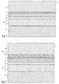
- a first embodiment of the heat protection layer according to the invention is shown, wherein the heat protection layer 1 is preferably applied to a substrate 2 by a plurality of successive sputtering operations.
- a metallic layer 3 is applied to the substrate 2, which may be, for example, a flat glass.
- the metallic layer 3, which preferably consists of silver, is arranged between a dielectric lower layer 4 and a dielectric upper layer 5.
- the dielectric underlayer 4 and the dielectric top layer 5 are antireflective layers, by which a high transmission of the coated substrate 2 in the visible range is achieved.
- the dielectric lower layer 4 consists of a first layer 4 'and a second layer 4' '.
- a bismuth oxide layer is preferably applied directly to the glass substrate.
- the layer bismuth oxide has a thickness of 5 to 50 nm, and is in a reactive, d. H. oxygenated atmosphere sputtered.
- the target used contains a proportion of manganese in addition to the bismuth.
- the layer thickness is preferably between 10 nm and 40 nm, more preferably between 15 nm and 25 nm.
- a second layer 4 "of the dielectric underlayer 4 is applied, which preferably consists of zinc oxide.
- the mixed target preferably contains zinc oxide and aluminum oxide (ZnO x , Al 2 O 3 ).
- the use of such a mixing target leads to a reduction of the sheet resistance and thus to a reduction of the emissivity ⁇ .
- the layer thickness of the applied zinc oxide is between 1 nm and 15 nm, preferably between 4 nm and 11 nm, more preferably between 5 nm and 8 nm.
- a particularly advantageous arrangement results in a total layer thickness of the dielectric lower layer of 26 nm, with a first layer 4 'of 20 nm and a second layer 4 '' with 6 nm.
- a layer 3 of a metal follows, wherein preferably a silver layer is applied.
- the silver layer has a preferred thickness of 5 nm to 15 nm, with a thickness of 9 nm being found to be a particularly suitable layer thickness, in particular in connection with the particularly preferred layer thickness of 26 nm of the dielectric underlayer 4.
- the dielectric top layer 5 consists in the simplest case of a zinc oxide layer, wherein between the dielectric top layer 5 and the metallic layer 3, a blocking or adhesive layer 7, e.g. made of titanium oxide, is arranged. If the dielectric top layer 5 consists exclusively of a zinc oxide layer, then the dielectric top layer 5 preferably has a thickness of 10 nm to 70 nm, preferably a thickness of 20 nm to 60 nm, particularly preferably a thickness of 30 nm to 50 nm By way of example, the structure of the heat-insulating layer shown as an example turns out to be particularly favorable for a thickness of 40 nm.
- composition of the individual layers in all layers can deviate from the stoichiometrically exact ratios for bismuth oxide, zinc oxide, tin oxide and zinc stannate.
- oxides instead of the oxides, corresponding nitrides or oxynitrides can also occur if nitrogen or a mixture of oxygen and nitrogen is used as the reactive gas in the process.
- a second embodiment is in the Fig. 2 shown.
- the heat protection layer is in turn applied to a substrate 2, which preferably consists of flat glass, and has a metallic layer 3, which is applied to a dielectric underlayer 4, which consists of a first layer 4 'and a second layer 4''.
- the first layer 4 'and the second layer 4'' are in their construction with the first layer 4' and the second layer 4 '' from Fig. 1 identical and are also applied by the same method.
- a dielectric top layer 6 is applied, which consists of a first layer 6 'and a second layer 6''.
- the first layer 6 ' corresponds in its structure and with respect to the method for depositing the dielectric upper layer 5 from the example Fig. 1 , In addition, however, a second layer 6 "is applied which contains zinc stannate.
- the zinc oxide of the first layer 6 'of the dielectric top layer 6 has a thickness of 1 nm to 15 nm, preferably a thickness of 4 nm to 12 nm, particularly preferably a thickness of 5 nm to 9 nm.
- the dielectric top layer 6 has a thickness of 10 nm to 70 nm, preferably a thickness of 20 nm to 60 nm, particularly preferably a thickness of 30 nm to 50 nm.
- an adhesive layer 7 is arranged between the metallic layer 3 and the dielectric top layer 6.
- the adhesive layer 7 is preferably made of titanium oxide and preferably has a thickness between 1 nm and 5 nm, with a layer thickness of 2 nm being particularly preferred with regard to an optimized transmission in the visible range of the light.
- the total layer thickness of the dielectric top layer 6 is 48 nm, and for the first layer 6 ', which consists of zinc oxide, a layer thickness of 8 nm is provided, and for the final zinc stannate layer has a thickness of 40 nm.
- tungsten oxide in the layer structure.
- the use of zinc stannate produces a top layer which has excellent properties in terms of durability, so that an additional protective layer can be dispensed with.
- the layer system in the edge region of the substrate 2 is easy to abradable, so that an exemption of the substrate 2 from the heat protection layer to build the substrates to a heat protection glazing is possible.
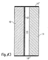
- a heat protection glazing which is composed of several flat glasses is in Fig. 3 shown schematically.
- the illustrated Embodiment has a first disc 10 and a second disc 11 which are interconnected, wherein the connection is indicated by the edge elements 14 and 14 'shown in black.
- the heat protection layer 12 On the second disc 11 facing side of the first disc 10, the heat protection layer 12 according to the invention is applied.
- a space 13 is formed, which may be filled with an inert gas.
- the coated pane has a light transmission ⁇ L measured according to DIN 67507 in the visible wavelength range of at least 88%.
- the heat shielding layer system described has a light transmission ⁇ L of more than 79% in the visible region of the light.
- a color rendering index R a, D of ⁇ 97 or R a, R of likewise ⁇ 97 is achieved.
- the emissivity ⁇ n remains below 0.06.
- FIG. 4 An example of a profile 16 of the transmission T and a profile 17 of the reflection R on a heat protection layer 1 with the layer structure of the embodiment of Fig. 1 (Float Glass / BiO x / ZnO x: AlO x / Ag / TiO x / ZnO x: AlO x) is in Fig. 4 shown.
- the transmission T and the reflection R are plotted against the wavelength and expressed in percent. Good to see is the low reflection in the visible range of light.
- the substrate itself has an absorption of about 2%, so that only about 5% absorption in the layer occur, the emissivity ⁇ n always less than 0.06 remains.
- a further layer can be applied, preferably of SiO x , which further improves the already good photometric properties, as well as the resistance.
Landscapes
- Chemical & Material Sciences (AREA)
- Life Sciences & Earth Sciences (AREA)
- Engineering & Computer Science (AREA)
- Chemical Kinetics & Catalysis (AREA)
- General Chemical & Material Sciences (AREA)
- Geochemistry & Mineralogy (AREA)
- Materials Engineering (AREA)
- Organic Chemistry (AREA)
- Laminated Bodies (AREA)
- Surface Treatment Of Glass (AREA)
Claims (18)
- Substrat recouvert d'une couche de protection thermique, un système de couche étant appliqué sur le substrat (2), avec au moins
une couche inférieure diélectrique (4), qui comprend au moins deux couches différentes (4', 4"), les couches (4', 4") se composant respectivement d'un oxyde ou d'un nitrure d'un métal différent ou d'un semi-conducteur,
une couche métallique (3),
une couche supérieure diélectrique (5, 6), laquelle comprend au moins une couche (5, 6) dont le composant principal est l'oxynitrure de zinc, ou laquelle comprend au moins une première couche (6'), dont le composant principal est l'oxyde de zinc ou l'oxynitrure de zinc, et une seconde couche (6"), dont le composant principal est le stannate de zinc, qui présente une épaisseur allant de 10 nm à 70 nm dans le cas où la première couche (6') présente de l'oxyde de zinc en tant que composant principal, l'indice de réfraction de la couche inférieure diélectrique (4) étant plus élevé que l'indice de réfraction de la couche supérieure diélectrique (5, 6). - Substrat recouvert d'une couche de protection thermique selon la revendication 1,
caractérisé en ce
qu'au moins l'une des couches (4") de la couche inférieure diélectrique (4) comprend de l'oxyde de zinc en tant que composant principal. - Substrat recouvert d'une couche de protection thermique selon la revendication 2,
caractérisé en ce
que la couche (4"), dont le composant principal est l'oxyde de zinc, est contiguë à la couche métallique (3). - Substrat recouvert d'une couche de protection thermique selon la revendication 2 ou 3,
caractérisé en ce
que la couche (4"), dont le composant principal est l'oxyde de zinc, présente une épaisseur allant de 1 nm à 15 nm, de préférence une épaisseur allant de 4 nm à 11 nm, de manière particulièrement préférée une épaisseur allant de 5 nm à 8 nm. - Substrat recouvert d'une couche de protection thermique selon l'une quelconque
des revendications 1 à 4,
caractérisé en ce
que la couche diélectrique (4) présente une couche (4'), qui comporte de l'oxyde de bismuth ou de l'oxyde de tungstène en tant que composant principal. - Substrat recouvert d'une couche de protection thermique selon la revendication 5,
caractérisé en ce
que la couche (4'), dont le composant principal est l'oxyde de bismuth ou l'oxyde de tungstène, présente une épaisseur allant de 5 nm à 50 nm, de préférence une épaisseur allant de 10 nm à 40 nm, de manière particulièrement préférée une épaisseur allant de 15 nm à 25 nm. - Substrat recouvert d'une couche de protection thermique selon l'une quelconque des revendications 1 à 6,
caractérisé en ce
que la couche (5) avec le composant principal d'oxynitrure de zinc présente une épaisseur allant de 10 nm à 70 nm, de préférence une épaisseur allant de 20 nm à 60 nm, de manière particulièrement préférée une épaisseur allant de 30 nm à 50 nm. - Substrat recouvert d'une couche de protection thermique selon l'une quelconque des revendications 1 à 7,
caractérisé en ce
que la couche avec le composant principal d'oxyde de zinc est la première couche (6') de la couche supérieure (6) observée depuis le substrat (2). - Substrat recouvert d'une couche de protection thermique selon l'une quelconque des revendications 1 à 8,
caractérisé en ce
qu'une couche adhésive (7) (Primer) est appliquée entre la couche métallique (3) et la couche supérieure diélectrique (6). - Substrat recouvert d'une couche de protection thermique selon la revendication 9,
caractérisé en ce
que la couche adhésive (7) (Primer) comprend de l'oxyde de titane en tant que composant principal. - Substrat recouvert d'une couche de protection thermique selon l'une quelconque des revendications 1 à 10,
caractérisé en ce
que le substrat recouvert (2) présente une émissivité ε inférieure ou égale à 0,06 et une transmission τL supérieure à 88 % pour la lumière dans le domaine visible. - Substrat recouvert d'une couche de protection thermique selon l'une quelconque des revendications 1 à 11,
caractérisé en ce
que le substrat recouvert (2) présente un indice de rendu des couleurs de Ra,D ≥ 97 et Ra,R ≥ 97. - Substrat recouvert d'une couche de protection thermique selon l'une quelconque des revendications 1 à 12,
caractérisé en ce
que le système de couche est appliqué sur un verre plat en tant que substrat (2). - Vitrage de protection thermique se composant d'au moins deux substrats (10, 11) disposés parallèlement l'un par rapport à l'autre,
caractérisé en ce
qu'au moins l'un des deux substrats (10) est un substrat recouvert d'une couche d'isolation thermique (12) selon l'une quelconque des revendications 1 à 15. - Procédé de fabrication d'un système de couche de protection thermique sur un substrat (2) selon la revendication 1, avec les étapes de procédé consistant à :- pulvériser une couche inférieure diélectrique (4) sur le substrat (2), la couche inférieure (4) étant formée par au moins deux couches (4', 4") pulvérisées l'une après l'autre et, lors de la pulvérisation, différentes cibles métalliques ou semiconductrices étant utilisées pour les couches (4', 4") au moins au nombre de deux ;- pulvériser une couche métallique (3) ;- pulvériser une couche supérieure diélectrique (5, 6), qui comprend au moins une couche (5) d'oxynitrure de zinc ou au moins une couche (6') d'oxyde de zinc ou d'oxynitrure de zinc et une couche (6") de stannate de zinc en tant que composants essentiels.
- Procédé selon la revendication 15,
caractérisé en ce
qu'un alliage de zinc et d'aluminium est utilisé lors de la pulvérisation de la couche (4") de la couche inférieure (4), qui comprend de l'oxyde de zinc en tant que composant essentiel. - Procédé selon la revendication 15,
caractérisé en ce
qu'une cible mélangée constituée d'oxydes de zinc et d'un dopage est utilisée lors de la pulvérisation de la couche (4") de la couche inférieure (4) qui comprend de l'oxyde de zinc en tant que composant essentiel. - Procédé selon l'une quelconque des revendications 15 à 17,
caractérisé en ce
qu'une couche adhésive (7) (Primer), qui comprend de l'oxyde de titane, est pulvérisée directement sur la couche métallique (3).
Applications Claiming Priority (3)
| Application Number | Priority Date | Filing Date | Title |
|---|---|---|---|
| DE2002152101 DE10252101A1 (de) | 2002-11-08 | 2002-11-08 | Mit einer Wärmeschutzschicht beschichtetes Substrat und Verfahren zum Aufbringen der Wärmeschutzschicht |
| DE10252101 | 2002-11-08 | ||
| PCT/EP2003/011081 WO2004041742A1 (fr) | 2002-11-08 | 2003-10-07 | Substrat recouvert d'une couche d'isolation thermique et procede pour etendre la couche d'isolation thermique |
Publications (2)
| Publication Number | Publication Date |
|---|---|
| EP1560797A1 EP1560797A1 (fr) | 2005-08-10 |
| EP1560797B1 true EP1560797B1 (fr) | 2008-12-17 |
Family
ID=32185382
Family Applications (1)
| Application Number | Title | Priority Date | Filing Date |
|---|---|---|---|
| EP03770959A Expired - Lifetime EP1560797B1 (fr) | 2002-11-08 | 2003-10-07 | Substrat recouvert d'une couche d'isolation thermique et procede pour etendre la couche d'isolation thermique |
Country Status (3)
| Country | Link |
|---|---|
| EP (1) | EP1560797B1 (fr) |
| DE (2) | DE10252101A1 (fr) |
| WO (1) | WO2004041742A1 (fr) |
Families Citing this family (5)
| Publication number | Priority date | Publication date | Assignee | Title |
|---|---|---|---|---|
| DE102004001655A1 (de) * | 2004-01-12 | 2005-08-04 | Interpane Entwicklungs- Und Beratungsgesellschaft Mbh & Co.Kg | Mit einer Wärmeschutzschicht beschichtetes Substrat |
| DE102005007826B4 (de) * | 2005-02-21 | 2019-05-23 | Interpane Entwicklungs- Und Beratungsgesellschaft Mbh & Co.Kg | Transparentes Substrat mit einem wärmereflektierenden Belag und Verfahren zu dessen Herstellung |
| DE102010008518B4 (de) * | 2010-02-18 | 2013-11-28 | Von Ardenne Anlagentechnik Gmbh | Wärmebehandelbares Infrarotstrahlung reflektierendes Schichtsystem und Verfahren zu dessen Herstellung |
| DE102012200799A1 (de) * | 2011-09-26 | 2013-03-28 | Interpane Entwicklungs-Und Beratungsgesellschaft Mbh | Brandschutzelement mit Schutzbeschichtung und dessen Herstellungsverfahren |
| DE102014108650A1 (de) * | 2014-06-20 | 2016-01-07 | Von Ardenne Gmbh | Stabiles IR-reflektierendes Schichtsystem und Verfahren zu dessen Herstellung |
Family Cites Families (4)
| Publication number | Priority date | Publication date | Assignee | Title |
|---|---|---|---|---|
| DE2854213C2 (de) * | 1978-12-15 | 1983-10-20 | Leybold-Heraeus GmbH, 5000 Köln | Verfahren zur Herstellung von zu Isolierscheiben verarbeitbaren, infrarotreflektierenden Fensterscheiben und deren Verwendung zur Herstellung von Isolierscheiben |
| GB8900165D0 (en) * | 1989-01-05 | 1989-03-01 | Glaverbel | Glass coating |
| DE19541937C1 (de) * | 1995-11-10 | 1996-11-28 | Ver Glaswerke Gmbh | Wärmedämmendes Schichtsystem mit niedriger Emissivität, hoher Transmission und neutraler Ansicht in Reflexion und Transmission |
| JP2000302486A (ja) * | 1999-04-15 | 2000-10-31 | Nippon Sheet Glass Co Ltd | 日射遮蔽性透光板およびこれを用いた日射遮蔽性複層透光板 |
-
2002
- 2002-11-08 DE DE2002152101 patent/DE10252101A1/de not_active Withdrawn
-
2003
- 2003-10-07 WO PCT/EP2003/011081 patent/WO2004041742A1/fr active Application Filing
- 2003-10-07 EP EP03770959A patent/EP1560797B1/fr not_active Expired - Lifetime
- 2003-10-07 DE DE50310944T patent/DE50310944D1/de not_active Expired - Lifetime
Also Published As
| Publication number | Publication date |
|---|---|
| WO2004041742A1 (fr) | 2004-05-21 |
| DE50310944D1 (de) | 2009-01-29 |
| DE10252101A1 (de) | 2004-05-27 |
| EP1560797A1 (fr) | 2005-08-10 |
Similar Documents
| Publication | Publication Date | Title |
|---|---|---|
| EP0671641B1 (fr) | Revêtement à multicouches | |
| EP0090403B1 (fr) | Revêtement thermiquement isolant, sans influence sur l'aspect intérieur ou en vue par transparence et hautement transparent | |
| DE69825398T2 (de) | Durchsichtiges Substrat mit einem Dünnschichtaufbau mit Infrarot reflaktierenden Eigenschaften | |
| DE19852358C1 (de) | Thermisch hoch belastbares Low-E-Schichtsystem | |
| DE69920278T2 (de) | Verglasungsscheibe | |
| DE69925641T2 (de) | Verglasungsscheibe | |
| DE3027256C2 (fr) | ||
| EP2790916B1 (fr) | Verre composite destiné à être utilisé dans les véhicules ou en architecture | |
| WO2013083827A1 (fr) | Système stratifié de couleur stable, réfléchissant les ir et transparent et son procédé de fabrication, unité de verre | |
| DE2309288A1 (de) | Durchsichtige scheibe, insbesondere fensterscheibe, aus glas oder kunststoff mit waermereflektierender metallschicht | |
| EP3027573A2 (fr) | Système de couches d'un substrat transparent et procédé de production d'un système de couches | |
| WO2008017722A1 (fr) | Système de couches à conditionnement thermique réfléchissant le rayonnement infrarouge et procédé pour sa fabrication | |
| DE3503851A1 (de) | Hochtransparenter in durch- und aussenansicht neutral wirkender und waermedaemmender belag | |
| EP1560797B1 (fr) | Substrat recouvert d'une couche d'isolation thermique et procede pour etendre la couche d'isolation thermique | |
| DE102012207561A1 (de) | IR-reflektierendes, transparentes Schichtsystem und Verfahren zu dessen Herstellung | |
| DE3807600C2 (de) | Niederreflektierender, hochtransparenter in Durch- als auch in Außenansicht neutral wirkender Sonnenschutz- und/oder wärmedämmender Belag für ein Substrat aus transparentem Material, Verfahren zur Herstellung des Belags sowie Verwendungen des Belags | |
| EP0834483B1 (fr) | Revêtement multicouche thermiquement isolant pour un substrat transparent | |
| DE3906374A1 (de) | Verfahren zum herstellen von scheiben mit hohem transmissionsverhalten im sichtbaren spektralbereich und mit hohem reflexionsverhalten fuer waermestrahlung | |
| EP1123906B1 (fr) | Méthode pour la déposition des couches réfléchissantes la chaleur sur des substrats transparents et couches ainsi produites | |
| DE102013112990B4 (de) | Solar-Control-Schichtsystem mit intensivem Farbeindruck, Verfahren zu dessen Herstellung und Glaseinheit | |
| DE10046810C5 (de) | Verfahren zur Herstellung eines wärmereflektierenden Schichtsystems für transparente Substrate und danach hergestelltes Schichtsystem | |
| DE102011105718B4 (de) | Teiltransparentes Schichtsystem mit hoher IR-Reflexion, Verfahren zu dessen Herstellung sowie Architekturglaslement | |
| EP1553062B1 (fr) | Substrat revetu d une couche d isolation thermique | |
| EP1693351B1 (fr) | Revêtement réflecteur de chaleur | |
| DE10217045A1 (de) | Passivhaus-taugliches Verglasungselement |
Legal Events
| Date | Code | Title | Description |
|---|---|---|---|
| PUAI | Public reference made under article 153(3) epc to a published international application that has entered the european phase |
Free format text: ORIGINAL CODE: 0009012 |
|
| 17P | Request for examination filed |
Effective date: 20050217 |
|
| AK | Designated contracting states |
Kind code of ref document: A1 Designated state(s): AT BE BG CH CY CZ DE DK EE ES FI FR GB GR HU IE IT LI LU MC NL PT RO SE SI SK TR |
|
| RBV | Designated contracting states (corrected) |
Designated state(s): DE FR GB |
|
| 17Q | First examination report despatched |
Effective date: 20060904 |
|
| GRAP | Despatch of communication of intention to grant a patent |
Free format text: ORIGINAL CODE: EPIDOSNIGR1 |
|
| GRAS | Grant fee paid |
Free format text: ORIGINAL CODE: EPIDOSNIGR3 |
|
| GRAA | (expected) grant |
Free format text: ORIGINAL CODE: 0009210 |
|
| AK | Designated contracting states |
Kind code of ref document: B1 Designated state(s): DE FR GB |
|
| REG | Reference to a national code |
Ref country code: GB Ref legal event code: FG4D Free format text: NOT ENGLISH |
|
| REF | Corresponds to: |
Ref document number: 50310944 Country of ref document: DE Date of ref document: 20090129 Kind code of ref document: P |
|
| PLBI | Opposition filed |
Free format text: ORIGINAL CODE: 0009260 |
|
| PLAX | Notice of opposition and request to file observation + time limit sent |
Free format text: ORIGINAL CODE: EPIDOSNOBS2 |
|
| 26 | Opposition filed |
Opponent name: PILKINGTON DEUTSCHLAND AG Effective date: 20090917 |
|
| PLAF | Information modified related to communication of a notice of opposition and request to file observations + time limit |
Free format text: ORIGINAL CODE: EPIDOSCOBS2 |
|
| PLBB | Reply of patent proprietor to notice(s) of opposition received |
Free format text: ORIGINAL CODE: EPIDOSNOBS3 |
|
| PLBP | Opposition withdrawn |
Free format text: ORIGINAL CODE: 0009264 |
|
| PLBD | Termination of opposition procedure: decision despatched |
Free format text: ORIGINAL CODE: EPIDOSNOPC1 |
|
| PLBM | Termination of opposition procedure: date of legal effect published |
Free format text: ORIGINAL CODE: 0009276 |
|
| STAA | Information on the status of an ep patent application or granted ep patent |
Free format text: STATUS: OPPOSITION PROCEDURE CLOSED |
|
| 27C | Opposition proceedings terminated |
Effective date: 20120218 |
|
| REG | Reference to a national code |
Ref country code: FR Ref legal event code: PLFP Year of fee payment: 13 |
|
| REG | Reference to a national code |
Ref country code: FR Ref legal event code: PLFP Year of fee payment: 14 |
|
| REG | Reference to a national code |
Ref country code: FR Ref legal event code: PLFP Year of fee payment: 15 |
|
| REG | Reference to a national code |
Ref country code: FR Ref legal event code: PLFP Year of fee payment: 16 |
|
| PGFP | Annual fee paid to national office [announced via postgrant information from national office to epo] |
Ref country code: FR Payment date: 20221020 Year of fee payment: 20 |
|
| PGFP | Annual fee paid to national office [announced via postgrant information from national office to epo] |
Ref country code: GB Payment date: 20221024 Year of fee payment: 20 Ref country code: DE Payment date: 20221031 Year of fee payment: 20 |
|
| REG | Reference to a national code |
Ref country code: DE Ref legal event code: R071 Ref document number: 50310944 Country of ref document: DE |
|
| REG | Reference to a national code |
Ref country code: GB Ref legal event code: PE20 Expiry date: 20231006 |
|
| PG25 | Lapsed in a contracting state [announced via postgrant information from national office to epo] |
Ref country code: GB Free format text: LAPSE BECAUSE OF EXPIRATION OF PROTECTION Effective date: 20231006 |
|
| PG25 | Lapsed in a contracting state [announced via postgrant information from national office to epo] |
Ref country code: GB Free format text: LAPSE BECAUSE OF EXPIRATION OF PROTECTION Effective date: 20231006 |