EP1560625B1 - Atraumatische sensorleitungsanordnungen - Google Patents
Atraumatische sensorleitungsanordnungen Download PDFInfo
- Publication number
- EP1560625B1 EP1560625B1 EP03799840A EP03799840A EP1560625B1 EP 1560625 B1 EP1560625 B1 EP 1560625B1 EP 03799840 A EP03799840 A EP 03799840A EP 03799840 A EP03799840 A EP 03799840A EP 1560625 B1 EP1560625 B1 EP 1560625B1
- Authority
- EP
- European Patent Office
- Prior art keywords
- inner lead
- sensor
- lead body
- outer lead
- sensors
- Prior art date
- Legal status (The legal status is an assumption and is not a legal conclusion. Google has not performed a legal analysis and makes no representation as to the accuracy of the status listed.)
- Expired - Lifetime
Links
Images



Classifications
-
- A—HUMAN NECESSITIES
- A61—MEDICAL OR VETERINARY SCIENCE; HYGIENE
- A61N—ELECTROTHERAPY; MAGNETOTHERAPY; RADIATION THERAPY; ULTRASOUND THERAPY
- A61N1/00—Electrotherapy; Circuits therefor
- A61N1/02—Details
- A61N1/04—Electrodes
- A61N1/05—Electrodes for implantation or insertion into the body, e.g. heart electrode
-
- A—HUMAN NECESSITIES
- A61—MEDICAL OR VETERINARY SCIENCE; HYGIENE
- A61N—ELECTROTHERAPY; MAGNETOTHERAPY; RADIATION THERAPY; ULTRASOUND THERAPY
- A61N1/00—Electrotherapy; Circuits therefor
- A61N1/02—Details
- A61N1/04—Electrodes
- A61N1/05—Electrodes for implantation or insertion into the body, e.g. heart electrode
- A61N1/056—Transvascular endocardial electrode systems
Definitions
- the invention relates to implantable medical devices (IMDs) and, more particularly, implantable leads that include implantable sensors for sensing conditions within a patient.
- IMDs implantable medical devices
- implantable leads that include implantable sensors for sensing conditions within a patient.
- An implantable medical device may include circuitry electrically coupled to one or more sensors to record patient conditions over time.
- an implantable lead is typically used to couple a sensor to circuitry within an IMD housing.
- electrochemical sensors are commonly used for diabetes patients, e.g., to monitor a patient's glucose levels.
- a lead can be implanted within a patient to deploy an electrochemical glucose sensor for sensing levels of glucose in the patient's blood stream.
- a distal end of the lead, which includes the electrochemical glucose sensor, may be positioned in the patient's blood stream, e.g., within a heart chamber.
- a proximal end of the lead may be coupled to circuitry within the IMD.
- the IMD may record the sensed conditions, which may be sent to an external programmer via telemetry, so that a physician can monitor the patient's blood glucose levels.
- the IMD may interpret the sensed conditions and possibly deliver therapy to the patient, e.g., by delivering doses of insulin or drug therapy to the patient if sensed glucose levels exceed one or more therapy thresholds.
- glucose sensors use electrochemical methods such as an electroenzymatic method in which blood glucose is oxidized under glucose-oxidase control, producing gluconic acid and hydrogen peroxide.
- the electrochemical glucose sensor can be used to sense levels of gluconic acid and/or hydrogen peroxide in order to estimate a patient's glucose levels.
- the glucose levels may be determined or sensed more directly by the electrochemical glucose sensor.
- an electrochemical glucose sensor on a medical lead facilitates a chemical process which can be identified by electrical signals to measure a patient's glucose levels.
- electrochemical glucose sensors In addition to electrochemical glucose sensors a number of other types of electrochemical sensors have been developed to measure blood chemistry or the chemistry of other bodily fluids or material. In general, electrochemical sensors make use of one or more chemical processes and electrical signals can be used to measure conditions sensed by the chemical processes. Other types of sensors also exist including pressure sensors, optical sensors, and various other types of sensors.
- Electrochemical sensors and many other types of sensors typically suffer from stability and longevity problems.
- the electrochemical process used by electrochemical glucose sensors can cause significant depletion of the glucose sensors over time, eventually causing the glucose sensor to be ineffective for monitoring levels of glucose in the patient's blood stream.
- other sensors often have similar problems in that prolonged use causes depletion, wear or tissue overgrowth, which can undermine the sensing capabilities of the given sensor.
- Sensor replacement is a major concern because replacement of conventional electrochemical sensor leads is typically a very invasive medical procedure in which a lead is removed from a patient's blood vessel, and a new lead is inserted to a high blood flow location, such as inside a heart chamber.
- the new electrochemical sensor lead is typically inserted through the same blood vessel used for the previous electrochemical sensor lead. Removal of the lead can be very traumatic because of fibrosis around the lead.
- repeated implantation of new leads can cause damage and scarring to the patient's blood vessel, making subsequent implantation more difficult and more dangerous to the patient. Infection is also a concern.
- the invention provides an assembly or lead as defined in the independent claims.
- a sensor lead assembly includes an outer lead body and an inner lead including a sensor.
- the sensor may comprise an electrochemical sensor, or another sensor for which replacement during the life of the patient is anticipated.
- the inner lead can be positioned within an inner conduit defined by the outer lead body.
- the outer lead body may be permanently implanted in the patient and removably attached to an implantable medical device.
- the inner lead can be implanted through the inner conduit of the outer lead body.
- the electrochemical sensor of the inner lead has been depleted or otherwise exhausted its useful life, the inner lead can be removed, and a new inner lead can be implanted in place of the old inner lead.
- this replacement procedure is much less invasive and less traumatic than conventional lead replacement procedures. For example, while the outer lead body remains substantially in place, the replaceable inner lead avoids substantial contact and attachment to blood vessel tissue during replacement and use.
- the outer lead body may.define a window that exposes one of a plurality of electrochemical sensors positioned along axial positions of the inner lead.
- the inner lead may be axially repositioned relative to the window of the outer lead body to expose a new electrochemical sensor.
- this repositioning of the inner lead relative to the window of the outer lead body may be performed by an implantable medical device (IMD), avoiding a re-implantation procedure altogether.
- IMD implantable medical device
- the invention provides an electrochemical lead assembly comprising an outer lead body for substantially permanent implantation in a patient.
- the outer lead body can be formed with an inner conduit.
- the electrochemical lead assembly may also include an inner lead positioned in the inner conduit of the outer lead body, the inner lead including an electrochemical sensor positioned in proximity to a distal end of the inner lead.
- the invention provides an implantable medical device, such as an implantable sensing device for sensing patient conditions.
- the implantable medical device may include a housing including circuitry for storing sensed conditions, and an outer lead body mechanically coupled to the housing.
- the outer lead body can be formed with a conduit.
- the implantable medical device may also include an inner lead positioned in the conduit of the outer lead body and electrically coupled to the circuitry in the housing at a first end of the inner lead.
- the inner lead may include an electrochemical sensor positioned in proximity to a distal end of the inner lead, or another type of sensor for which replacement is commonly anticipated.
- the invention provides an outer lead body for substantially permanent implantation in a patent.
- the outer lead body may include a first end formed for mechanical attachment to an implantable medical device, and a second end formed with a seal to be pierced by an inner lead.
- a conduit for receiving the inner lead may be formed in the outer lead body between the first and second end.
- the invention provides an inner lead.
- the inner lead may include a lead body defining a first end and a second end, and a plurality of sensors formed along axial positions of the lead body in proximity to the first end.
- the lead may also include an electrical contact formed on the lead body in proximity to the first end, wherein each of the sensors is electrically coupled to the electrical contact.
- the invention may be capable of providing a number of advantages.
- the invention can greatly simplify, or in some cases, eliminate implantation procedures for electrochemical sensor replacement.
- electrochemical sensor replacement, and other types of sensor replacement is a major concern because replacement of conventional sensor leads is typically a very invasive medical procedure in which a lead is removed from a patient's blood vessel, and a new lead is inserted.
- the invention provides various alternatives to conventional lead replacement that are much less invasive and traumatic to a patient. In this manner, the invention can improve patient care and comfort, avoid infection, and generally improve therapy to the patient.
- conventional sensor replacement is a barrier to patient care
- the invention may remove the barrier, possibly causing physicians to be more willing to use sensors in patient care.
- the invention is directed to lead configurations for sensors that allow for atraumatic sensor replacement procedures.
- Various embodiments of the invention are directed to implantable medical devices (IMDs), lead assemblies, outer lead bodies, inner leads, which can be used in various sensor replacement methods, including improved implantation procedures that may be executed by a physician, as well as sensor replacement procedures that may be executed by an IMD.
- IMDs implantable medical devices
- lead assemblies outer lead bodies
- inner leads which can be used in various sensor replacement methods, including improved implantation procedures that may be executed by a physician, as well as sensor replacement procedures that may be executed by an IMD.
- a sensor lead assembly in one configuration, includes an outer lead body and an inner lead including an electrochemical sensor.
- the inner lead may be positioned within an inner conduit defined by the outer lead body.
- the lead assembly may be connected to a housing of an IMD.
- the outer lead body may be substantially permanently implanted in the patient, and the inner lead can be implanted through the conduit of the outer lead body. Then, once the electrochemical sensor of the inner lead has been depleted, become overgrown with tissue, or otherwise exhausted its useful life, the inner lead can be removed, and a new inner lead can be implanted to replace the old inner lead with the depleted sensor.
- the replacement procedure associated with this embodiment may be executed by a physician, but may be much less invasive and traumatic than conventional lead replacement procedures. For example, the replacement procedure may be subcutaneous.
- the outer lead body may define a window that exposes one of a plurality of electrochemical sensors positioned along axial positions of the inner lead.
- a physician may reposition the inner lead relative to the window to expose a new electrochemical sensor, or alternatively, an IMD may be programmed to reposition the inner lead relative to the window to expose a new electrochemical sensor, e.g., upon determining that the previously exposed electrochemical sensor has worn out.
- the replacement procedure associated with this embodiment may be executed by a physician or an IMD.
- the IMD may include a motor or other actuator capable of causing axial displacement of the inner lead. If executed by the IMD, the replacement procedure may avoid a subsequent implantation procedure altogether.
- electrochemical sensors may find useful application with a wide variety of other types of sensors including oxygen sensors, pressure sensors, optical sensors, and many other types of sensors.
- the sensors are non-electrode sensors, i.e., non-stimulative. If removal or replacement of the non-electrode sensor is desirable, then the teaching herein may be used to replace the sensor lead in response to such tissue overgrowth.
- FIG. 1 is a conceptual diagram illustrating an exemplary implantable medical device (IMD) 10 in a human body 5.
- IMD 10 comprises a housing 12 containing various circuitry that controls IMD operations and records sensed events. Housing 12 is typically hermetically sealed to protect the circuitry. Housing 12 may also house an electrochemical cell, e.g., a lithium battery for powering the circuitry, or other elements.
- the circuitry within housing 12 may be coupled to an antenna to transmit and receive information via wireless telemetry signals. Accordingly, conditions sensed by IMD 10 may be sent to an external programmer so that a physician can examine the sensed conditions for diagnostic purposes.
- IMD 10 also comprises a lead assembly that includes an outer lead body 16 and an inner lead 18 positioned within an inner conduit of outer lead body 16.
- Outer lead body 16 may be implanted through a blood vessel of human body 5 and fed into a heart chamber.
- An anchoring structure 19 may anchor outer lead body 16 in proximity to its entry point into the venous system.
- outer lead body 16 can be implanted in human body 5 in a substantially permanent manner. In other words, outer lead body 16 may remain implanted within body 5 even though inner lead 18 may be withdrawn and replaced from time to time.
- inner lead 18 comprises a removable lead that can be removed from the conduit of outer lead body 16 without removing outer lead body 16 from human body 5.
- inner lead 18 can be removed from human body 5 and replaced with a relatively simple replacement procedure that is much less invasive and much less traumatic than conventional implantation procedures.
- Inner lead 18 comprises a lead body that includes an electrochemical sensor in proximity to a distal tip of inner lead 18, or another sensor element that has a relatively short useful life.
- Electrochemical sensors refer to sensors that make use of one or more chemical processes and electrical signals. In particular, the electrical signals may change with certain chemical processes and thereby identify conditions in a patient.
- electrochemical sensors Several types of electrochemical sensors have been developed including electrochemical glucose sensors, electrochemical oxygen sensors, and the like. The problem with such electrochemical sensors, however, is that they generally have a relatively short useful life. In particular, the chemical processes can cause corrosion and depletion of the electrochemical sensor, which eventually renders the sensor ineffective for its sensing purposes. Tissue overgrowth may also render the sensor ineffective. When the sensor is rendered ineffective, the electrochemical sensor typically requires replacement.
- the "outer-inner" lead assembly configuration described herein is one example of a lead assembly that can facilitate less invasive and less traumatic sensor replacement than conventional implantation. The invention may find useful application with electrochemical sensor leads, or other types of sensor leads
- IMD 10 may comprise sensing device that senses conditions of human body 5 and stores the sensed conditions.
- IMD 10 may support telemetry communication with an external programmer in order to allow the sensed information to be delivered to a physician for analysis.
- the invention is not necessarily limited to use with passive sensing devices, but may also find application in devices that actively deliver therapy to the patient.
- the circuitry in housing 12 may interpret sensed conditions, and deliver therapy to human body 5 in response to the sensed conditions.
- the therapy may comprise therapeutic electrical pulses, drug delivery, or the like.
- the electrochemical sensor on the distal tip of inner lead 18 would comprise a electrochemical glucose sensor positioned in a high blood flow location such as in a chamber of the heart.
- the invention is not necessarily limited to glucose sensors, or even electrochemical sensors, and may find useful application in any sensor applications in which sensor replacement is commonly required.
- the sensors may be non-electrode sensors for which tissue overgrowth over the sensor is generally undesirable.
- Diabetes mellitus is the most common of endocrine disorders, and is characterized by inadequate insulin action. Diabetes mellitus has two principal variants, known as Type I diabetes and Type II diabetes. The latter is also referred to as DM/II (diabetes mellitus type II), adult-onset diabetes, maturity-onset diabetes, or NIDDM (non-insulin dependent diabetes mellitus).
- Type I diabetes is usually diagnosed in children and young adults. In Type I diabetes, the body does not produce insulin. Insulin is necessary for the body to be able to use sugar. When sugar builds up in the blood instead of going into cells, it can cause problems such as a short-term lack of energy, and longer term problems with eyes, kidneys, nerves, the heart, or other organs or systems.
- Type II diabetes generally develops in adulthood, and the risk of development of Type II diabetes generally increases with age. Factors such as obesity also contribute to the risk.
- a patient suffering from Type II diabetes secretes insulin, but the insulin's target cells are less sensitive to insulin. Symptoms of Type II diabetes are typically slow to appear, and a patient having Type II diabetes may not be aware of his condition.
- a blood test may show whether the patient has impaired glucose tolerance (IGT), which is often a precursor to Type II diabetes, or compensated Type II diabetes. Unless addressed with treatment such as diet and exercise, these conditions may develop into uncompensated Type II diabetes, a very serious condition.
- ITT impaired glucose tolerance
- an IMD that includes a glucose sensor, e.g. to monitor levels of blood sugar.
- Most glucose sensors use electrochemical methods such as an electroenzymatic method in which blood glucose is oxidized under glucose-oxidase control, producing gluconic acid and hydrogen peroxide.
- the electrochemical glucose sensor can be used to sense levels of gluconic acid and/or hydrogen peroxide in order to estimate a patient's glucose levels.
- the glucose levels may be determined or sensed more directly by the electrochemical glucose sensor.
- an electrochemical glucose sensor on a lead facilitates a chemical process. Electrical signals can be used to identify these chemical processes on the electrochemical sensor in order to identify certain conditions indicative of a patient's glucose levels.
- Optical glucose sensors are also used in some cases, and may likewise benefit from the teaching herein.
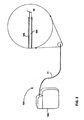
- FIG. 2 is a simplified schematic view of an exemplary glucose sensing IMD 10A with an enlarged view of a distal end of an exemplary implantable lead assembly.
- IMD 10A comprises a housing 12A which houses various circuitry that controls glucose sensing operations and records sensed events.
- IMD l0A also comprises a lead assembly 11 that includes an outer lead body 16A and an inner lead 18A positioned within a conduit of outer lead body 16A.
- Outer lead body 16A may be implanted through a blood vessel such as the superior vena cava of a patient to feed the distal end 20 of inner lead 18A into a high blood flow location.
- distal end 20 of inner lead 18A may be placed in a heart chamber such as the right atrium.
- the distal end 20 of inner lead 18A includes a glucose sensor for sensing glucose in the patients blood, e.g., an electrochemical glucose sensor.
- outer lead body 16A is generally implanted in the patient in a substantially permanent manner.
- Inner lead 18A comprises a removable lead that can be removed from the conduit of outer lead body 16A without removing outer lead body 16A from the patient. Accordingly, inner lead 18A can be removed from the conduit of outer lead body 16A and replaced with a relatively simple replacement procedure that is much less invasive and much less traumatic than conventional implantation procedures.
- FIG 3 is a simplified schematic view of first and second ends 31, 32 of an exemplary implantable lead assembly 30 including an outer lead body 36 and an inner lead 38 that includes an electrochemical sensor 39 such as an electrochemical glucose sensor.
- outer lead body 36 defines a conduit 37 sized to receive inner lead 38.
- inner lead 38 is sized for insertion into the conduit 37 of outer lead body 36.
- Inner lead 38 has sufficient rigidity to allow insertion and removal from conduit 37, and may include a lubrication layer to improve insertion or removal.
- a stylet or other structural enhancement may be used to provide added rigidity to inner lead 38 during insertion or removal.
- a first end 31A of inner lead 38 can be electrically coupled to an IMD.
- a second end 32A (the distal end) of inner lead 38 includes electrochemical sensor 39. Electrical signals can be used to measure chemical reactions that occur on sensor 39 in order to measure glucose levels in a patient.
- electrochemical sensor 39 is only one example of sensor that may be used on an inner lead in accordance with the invention. Pressure sensors, optical sensors, biological sensors, and a wide variety of non-electrode sensors for which tissue overgrowth is undesirable may benefit from the teaching herein.
- first and second ends 3 1 B and 32B of outer lead body 38 are formed with sealing mechanisms.
- first end 31B of outer lead body 36 is formed for sealed attachment to an IMD.
- protruding features 41 may be formed on outer lead body 36 in proximity to first end 31 to facilitate attachment to an IMD in a sealed fashion to ensure that body fluid cannot enter conduit 37.
- the second end 32B of outer lead body 36 may be formed with a seal 42 that is pierced by inner lead 38 upon insertion of inner lead through conduit 37.
- seal 42 may comprise a silicone material to ensure that fluid cannot penetrate into conduit 37.
- FIGS. 4 and 5 are enlarged cross-sectional views of distal ends (second ends) of exemplary outer lead bodies that may correspond to outer lead body 36 of FIG. 3.
- outer lead body 48 is formed with a seal 44 on its distal tip. This seal 44 can be pierced by an inner lead upon insertion of the inner lead into conduit 47. Seal may be pre-slit with a resealable slit 45 to simplify piercing through seal 44. Seal 44 may define a spring force about slit 45 upon piercing slit 45 with an inner lead.
- seal 44 can help ensure that minimal fluid, tissue, proteins, and/or cells are able to enter conduit 47 upon insertion of outer lead body 48 into a patient and may define a good fluid-tight seal upon being pierced by an inner lead. Seal 44 may also be very useful in limiting or avoiding fibrous tissue growth between an inner lead and outer lead body 48.
- Outer lead body 48 may also include a metal portion 49, such as a metal band, in proximity to the distal end in order to facilitate location in the human body via an electromagnetic radiation source.
- a metal portion 49 such as a metal band
- Other radio opaque material may also be used to realize portion 49, including for example, a metal powder molded with the plastic lead body 48.
- X-rays, radio waves, or other electromagnetic radiation may be used to pinpoint portion 49 within a patient, allowing a physician to implant outer lead body 48 in a desired location with great accuracy.
- portion 49 may comprise a platinum material welded to a major portion 46 of outer lead body 48.
- Major portion 46 may have sufficient rigidity to ensure that it will not collapse under pressure of anchoring structure 19 (FIG.
- Major portion 46 may also include a coiled layer (not shown) to avoid collapse of major portion if major portion 46 it is bent during the implantation of outer lead body 48.
- FIG. 5 illustrates an alterative configuration of outer lead body 58 formed with a redundant seal 54 on its distal tip.
- the redundant seal 54 defines a plurality of sealing structures 55A, 55B, 55C that can be pierced by an inner lead upon insertion of the inner lead into conduit 57.
- Such redundant sealing can further ensure that fluid does not enter conduit once sealing structures 55A-55C have been pierced by an inner lead.
- Each of the plurality of sealing structures 55A, 55B, 55C may be pre-slit with respective resealable slits 56A, 56B, 56C to simplify piercing through the respective seal.
- FIG. 6 is a perspective view of an IMD 10C.
- IMD 10C comprises a housing 62 and an electrochemical lead assembly including an inner lead 64 and an outer lead body 66.
- housing may 62 include a connector module 65 that facilitates electrical coupling of inner lead 64 to circuitry within housing 62.
- Outer lead body 66 is formed with a conduit that mates with inner lead 64. Accordingly, upon implantation of outer lead body 66, inner lead 64 can be removably inserted into the conduit of outer lead body 66. Thus, if inner lead 64 wears out, a new inner lead can be inserted in its place with a very non-invasive subcutaneous medical procedure that is less traumatic to a patient than conventional replacement procedures.
- Outer lead body 66 includes a sealing structure 67 to facilitate a sealed engagement with connector module 65.
- Fig. 6 illustrates outer lead body pulled back from connector module so that sealing structure 67 may be seen.
- Connector module 65 includes a channel 71 through which inner lead 64 can be removed from IMD 10C, e.g., by pulling on the proximal end 72 of inner lead 64 to slide inner lead 64, per arrow A, from the conduit of outer lead body 66 and through channel 71.
- inner lead 64 may be removed from the conduit of outer lead body 66 through channel 71 of connector module 65.
- a new inner lead, also identified as item 64, can then be inserted, per arrow B, through channel 71 and into the conduit of outer lead body. In that case, outer lead body 66 may not need to be removed from connector module 65.
- inner lead 64 may also be formed with a sealing ring 74 to seal against connector module 65.
- inner lead 64 may also include a mechanical stop 76 to ensure that proximal end of inner lead 64 cannot be inserted too far into connector module 65.
- An end cap 78 may be provided to cover the proximal end 72 of inner lead 64, e.g., by screwing onto connector module 65.
- FIG 7 is a cross-sectional side view of another embodiment of an IMD 80.
- IMD 80 comprises a housing 82 and a electrochemical lead assembly including an inner lead 84 and an outer lead body 86.
- Inner lead 84 defines a lead body that includes a plurality of electrochemical sensors 87A-87C formed along axial positions of the lead body in proximity to a distal end of inner lead.
- the proximal end of inner lead may include one or more electrical contacts (not shown).
- each of the electrochemical sensors 87A-87C may be electrically coupled to the electrical contact area on the proximal end.
- the electrical contact may define a plurality of electrical contact areas formed at axial positions along the length of the lead body in proximity to the proximal end.
- Each of the electrochemical sensors 87A-87C is electrically coupled to a corresponding one or more of the plurality of electrical contact areas.
- Electrical components housed in housing 82 can be electrically coupled to electrochemical sensors 87A-87C so that sensed conditions can be stored or logged by the circuitry.
- Outer lead body 86 may be formed with a window 85 in proximity to a distal end of outer lead body 86. Seals (not shown) may seal an exposed portion of inner lead 84 at window 85 from the conduit of outer lead body. In other words, seals may be provided in proximity to window 85 to seal an exposed sensor from the conduit and to seal non-exposed sensors from patient fluids and the like.
- One of sensors 87 can be positioned relative to window 85 for sensing purposes.
- IMD 80 may be caused to rotate reel 89 or a similar structure, to expose a new electrochemical sensor, e.g., sensor 87B to window 85 This rotation of reel 89 or a similar structure may be performed in response to a physician activated programming routine, mechanical screwing by the physician, or automatically activated rotation by IMD 80 upon determining that sensor 87A has worn out. If IMD 80 causes automated rotation of reel 89, IMD 80 may include a motor for performing such rotation. In any case, such repositioning of sensors 87 of inner lead 84 relative to window 85 of outer lead body 86 can provide sensor replacement with an atraumatic medical procedure, or possibly no medical procedure.
- FIGS. 8-10 illustrate another configuration of IMD 90.
- IMD 90 comprises a housing 92 and a electrochemical lead assembly including an inner lead 94 and an outer lead body 96.
- Inner lead 94 defines a lead body that includes a plurality of electrochemical sensors 97A-97C formed along axial positions of the lead body in proximity to a distal end of inner lead 94.
- the proximal end of inner lead 94 may include one or more electrical contacts areas 98A-98C.
- each of the electrochemical sensors 97A-97C may be electrically coupled to a corresponding one of the plurality of electrical contact areas 98A-98C.
- electrical components housed in housing 82 can be electrically coupled to electrochemical sensors 97A-97C so that sensed conditions can be stored or logged by the electrical components.
- Outer lead body 96 may be formed with a window 95 in proximity to a distal end of outer lead body.
- One of sensors 97A can be positioned relative to window 95 for sensing purposes.
- sensor 97A wears out, a relatively simple subcutaneous medical procedure may be performed in which a physician accesses housing 92, such as via a small incision into the patient.
- End cap 100 is removed as illustrated in FIG. 9, and inner lead 94 is repositioned by a physician relative to outer lead body 96.
- inner lead 94 may be repositioned relative to outer lead body 96 to expose a new sensor 97B to window 95, and possibly to expose a new electrical contact area 98B to circuitry within housing 92.
- Contact area 98A may correspond to electrochemical sensor 97A
- contact area 98B may correspond to electrochemical sensor 97B
- An electrical contact, shown as arrow C in Figs. 8-10, within housing 92 may be positioned such that when a new sensor 97B is positioned relative to window 95, a corresponding electrical contact area 98B is positioned for electrical contact with circuitry in housing 92.
- a portion 102 of inner lead 94 may be cut by the physician, and end cap 100 can be replaced as illustrated in FIG. 10. In this manner, a relatively simple electrochemical sensor replacement procedure can be used instead of more invasive conventional lead replacement procedures.
- sensors may be positioned at a same axial location about the diameter of the inner lead.
- repositioning the inner lead with respect to the outer lead body may comprise rotating the inner lead relative to the outer lead body to expose a new sensor to a window of the outer lead body.
- FIGS. 11 and 12 are flow diagrams illustrating sensor implantation and replacement techniques.
- F1G 11 illustrates a sensor implantation and replacement technique, using implantable systems which are in accordance with embodiments of the invention in which an IMD similar to those illustrated in FIG 1, FIG. 2 or FIG. 6 is used.
- IMD 10 of FIG. 1 will be used in describing FIG 11.
- a physician implants an outer lead body 16 in a substantially permanent location of the patient (111).
- the physician may insert outer lead body 16 through the superior vena cava and feed outer lead body 16 into a heart chamber.
- the outer lead body 16 may be secured to the patient by anchoring structure 19, e.g., to the connective tissues of the patient in proximity to the entry point of the superior vena cava.
- One or more sutures may also be used to secure outer lead body 16.
- the physician may use x-ray or radio wave techniques to locate a metal portion 49 (FIG. 4) of outer lead body 16.
- the physician implants inner lead 18 through a conduit of outer lead body 16 (112).
- the physician can insert inner lead 18 through the conduit of outer lead body, eventually piercing a seal 44 or 54 (FIG.S. 4 and 5) on the distal end of outer lead body 16.
- a lubricant may be added to inner lead 18 to improve the insertion through the conduit of outer lead body 16.
- the insertion of the inner lead into the outer lead body (112) may be performed prior to implantation of the outer lead body (111). In that case, both outer lead body and inner lead would be inserted into the patient at the same time.
- physician may use Fluorscopy to visualize a sensor location relative to a distal end of the outer lead body 18.
- marks or radio opaque material on the inner lead may be used to help the physician location the correct implantation point.
- inner lead 18 and outer lead body 16 can be connected to a housing 12 of IMD 10 (113).
- the inner lead 18 may be electrically coupled to circuitry within housing 12, and outer lead body 18 may be coupled to housing 12.
- Outer lead body 18 may be formed with one or more structures on a proximal end to ensure a tight seal at housing 12, yet still allow for removal and reattachment of outer lead body 18 to housing 12 at a later time.
- IMD 10 can then be used to sense medical conditions within the patient (114).
- an electrochemical sensor such as a glucose sensor
- electrical signals may be affected by such chemical processes to identify such conditions.
- the sensed conditions may be stored by circuitry within housing 12, and possibly telemetrically transmitted to a programmer so that a physician can interpret the meaning of the sensed conditions and diagnose the patient accordingly.
- the electrochemical sensor of inner lead 16 may wear out (yes branch of 115).
- the relatively short useful life of electrochemical leads is a major concern.
- a relatively simple and non-invasive procedure may be performed to replace inner lead 16.
- the physician can remove inner lead 16 from outer lead body 18 (116), and a new inner lead can be inserted in the conduit of outer lead body 18 (117).
- the physician may use Fluorscopy to visualize a sensor location relative to a distal end of the outer lead body 18. Also marks or radio opaque markers on the new inner lead may be used to help the physician location the correct implantation point.
- outer lead body 18 By leaving outer lead body 18 permanently implanted, new inner leads can be easily inserted. Only a relatively small incision may be required to access housing 12 so that, for example, inner lead 16 may be removed from conduit of outer lead body 18 through channel 71 and a new inner lead may be inserted through channel 71 and into conduit of outer lead body 18. Alternately, outer lead body 18 can be unattached, and inner lead 16 can be pulled from the conduit of outer lead body. If desired, mounting structure 19 may be removed during the replacement procedure and then reattached following replacement of inner lead 16.
- outer lead body 18 may be desirable to flush outer lead body 18, e.g. with a saline solution following removal of inner lead 16 and prior to insertion of a new inner lead.
- an anti-inflammatory agent such as a steroid may be provided on the distal end of the new inner lead, e.g., to help limit or avoid fibrous tissue growth onto the new inner lead.
- An anti-biotic agent may also be used to flush the outer lead to help avoid patient infections.
- FIG. 12 illustrates a sensor implantation and replacement technique in which an IMD similar to those illustrated in FIG. 7-10.
- IMD 80 of FIG 7 will primarily be used in describing FIG. 12.
- a physician implants an outer lead body 86 in a substantially permanent location of the patient (121).
- the physician may insert outer lead body 80 through the superior vena cava and feed outer lead body 16 into a heart chamber.
- the outer lead body 86 may be anchored by anchoring structure and or more sutures may also be used.
- Outer lead body 86 may include a rigid layer in a section where a suture or anchoring structure can be applied to avoid collapse of outer lead body when a suture is applied.
- outer lead body 86 In order to position outer lead body 86 in a proper location, the physical may use x-ray or radio wave techniques to locate a metal portion or other radio opaque material (similar to 49 of FIG 4) of outer lead body 86.
- the physician then implants a multi-sensor inner lead 84 through a conduit of outer lead body 86 (122).
- the insertion of multi-sensor inner lead 84 into outer lead body 86 (122) may be performed prior to implantation of outer lead body 86 (121).
- the physician may use fluoroscopy to visualize a sensor location relative to a distal end of the outer lead body 86.
- marks on multi-sensor inner lead 84 may be used to help the physician locate the correct implantation point.
- the proper implantation point may correspond to a location in which sensor 87A aligns with window 85.
- multi-sensor inner lead 84 can be connected to circuitry and outer lead body 86 can be connected to a housing 82 of IMD 80 (123).
- Outer lead body 86 may be formed with one or more structures on a proximal end to ensure a tight hermetic seal at housing 82.
- IMD 10 can then be used to sense medical conditions within the patient (124).
- a sensor 87A proximate to window 85 such as an electrochemical sensor may be used to sense conditions.
- the sensed conditions may be stored by circuitry within housing 82, and possibly telemetrically transmitted to a programmer so that a physician can interpret the meaning of the sensed conditions and diagnose the patient accordingly.
- sensor 87A may wear out (yes branch of 125).
- multi-sensor inner lead 86 can be moved relative to the conduit of outer lead body to expose a new sensor, e.g. sensor 87B, to window 85.
- a proximal end of lead 86 may be coupled to a reel 89.
- Reel 89 may be caused to move, such as via programming signals sent from a physician, physical rotation by the physician, or possibly automatic movement caused by IMD 80 itself. In any case, rotation of reel 89 can cause a new electrochemical sensor, e.g. sensor 87B to be positioned relative to window. In this manner, sensor replacement can be greatly simplified.
- a configuration of IMD 90 like that illustrated in FIGS. 8-10 may be used.
- a physician can remove end cap 100 and pull on inner lead 94 by a sufficient amount to move sensor 97B into alignment with window 95. The physician can then cut portion 102 and replace the end cap 100 as illustrated in FIG. 10.
- the invention may be useful for electrochemical sensors, optical sensors, pressure sensors, blood borne biochemical or chemical sensors, lactate sensors used in the coronary sinus to detect ischemia, sensors for measuring CKMB, sensors for measuring Troponin I, T and C, sensors for measuring Myoglobin, sensors for measuring BNP (P-type natriuretic peptide), Micro Electro Mechanical Systems (MEMS) sensors or other types of medical sensors for which replacement during the life of the patient is anticipated.
- MEMS Micro Electro Mechanical Systems
Landscapes
- Health & Medical Sciences (AREA)
- Heart & Thoracic Surgery (AREA)
- Nuclear Medicine, Radiotherapy & Molecular Imaging (AREA)
- Cardiology (AREA)
- Engineering & Computer Science (AREA)
- Biomedical Technology (AREA)
- Radiology & Medical Imaging (AREA)
- Life Sciences & Earth Sciences (AREA)
- Animal Behavior & Ethology (AREA)
- General Health & Medical Sciences (AREA)
- Public Health (AREA)
- Veterinary Medicine (AREA)
- Vascular Medicine (AREA)
- Measurement Of The Respiration, Hearing Ability, Form, And Blood Characteristics Of Living Organisms (AREA)
- Electrotherapy Devices (AREA)
Claims (17)
- Implantierbare Anordnung mit:einem Gehäuse (12) einer implantierbaren medizinischen Einrichtung einschließlich eines Kanals (71) mit einer ersten Öffnung, einer zweiten Öffnung und einem elektrischem Kontakt, der innerhalb des Kanals zwischen der ersten Öffnung und der zweiten Öffnung aufgenommen ist,einem äußeren Leitungskörper (36) einschließlich eines nahen Endes, eines entfernten Endes und eines Leitungskanals (37), der sich von dem nahen Ende zu dem entfernten Ende erstreckt, undeiner inneren Leitung (38) einschließlich eines ersten Endes, eines zweiten Endes, einer Mehrzahl von Sensoren und einer Mehrzahl von elektrischen Kontakten, wobei die Mehrzahl von Sensoren in der Nähe des zweiten Endes der inneren Leitung positioniert und elektrisch mit entsprechenden elektrischen Kontakten der inneren Leitung gekoppelt ist und die Mehrzahl von elektrischen Kontakten der inneren Leitung in der Nähe des ersten Endes positioniert ist,wobei die erste Öffnung des Kanals für einen mechanischen Eingriff des nahen Endes des äußeren Leitungskörpers ausgelegt ist und sowohl die erste Öffnung als auch die zweite Öffnung des Kanals für einen Durchgang der inneren Leitung durch den Kanal ausgelegt sind.
- Implantierbare Anordnung nach Anspruch 1, die weiterhin einen Abdichtring (74) aufweist, der um das erste Ende der inneren Leitung nahe der Mehrzahl von Kontakten gebildet ist.
- Implantierbare Anordnung nach Anspruch 1 oder 2, die weiterhin einen mechanischen Anschlag (76) aufweist, der um das Ende der inneren Leitung gebildet ist.
- Implantierbare Anordnung nach Anspruch 1, 2 oder 3, die weiterhin eine entfernbare bzw. austauschbare Abschluss- bzw. Endkappe (78) aufweist, die ausgelegt ist, um die zweite Öffnung des Kanals abzudecken.
- Implantierbare Anordnung nach einem der vorstehenden Ansprüche, bei der die Mehrzahl von Sensoren der inneren Leitung einen Sensor (39) umfasst, der fern zu dem entfernten Ende des äußeren Leitungskörpers positioniert ist.
- Implantierbare Anordnung nach einem der vorstehenden Ansprüche, die weiterhin einen Abdichtmechanismus aufweist, der bei dem entfernten Ende des äußeren Leitungskörpers gebildet und elastisch bzw. federnd um die innere Leitung angeordnet ist.
- Implantierbare Anordnung mit:einem Gehäuse (82) einer implantierbaren medizinischen Einrichtung einschließlich eines Umpositionierungsaufbaus (89) und eines Kanals (71) innerhalb des Verbindermoduls mit einer Öffnung und mit einem elektrischen Kontakt, der innerhalb des Kanals nahe der Öffnung aufgenommen ist,einem äußeren Leitungskörper (86) einschließlich eines nahen Endes, eines entfernten Endes und eines Leitungskanals, der sich von dem nahen Ende zu dem entfernten Ende erstreckt, undeiner inneren Leitung (84) einschließlich eines ersten Endes, eines zweiten Endes, einer Mehrzahl von Sensoren (87A, 87B, 87C) und einer Mehrzahl von elektrischen Kontakten, wobei die Mehrzahl von Sensoren in der Nähe des zweiten Endes der inneren Leitung positioniert und mit entsprechenden elektrischen Kontakten der inneren Leitung gekoppelt ist und die Mehrzahl von elektrischen Kontakten der inneren Leitung in der Nähe des ersten Endes positioniert ist,wobei die Öffnung des Kanals für einen mechanischen Eingriff des nahen Endes des äußeren Leitungskörpers und für einen Durchgang der inneren Leitung in den Kanal ausgelegt ist, unddas erste Ende der inneren Leitung an den Umpositionierungsaufbau angreift, wenn es innerhalb des Kanals positioniert ist.
- Implantierbare Anordnung nach einem der vorstehenden Ansprüche, bei der die innere Leitung gleitend an den Kanal angreift und der Leitungskanal des äußeren Leitungskörpers und zumindest einer der Mehrzahl der von elektrischen Kontakten der inneren Leitung elektrisch mit dem elektrischen Kontakt gekoppelt ist, der innerhalb des Kanals aufgenommen ist.
- Implantierbare Anordnung nach einem der vorstehenden Ansprüche, die weiterhin ein Fenster (85) aufweist, das in dem äußeren Leitungskörper gebildet und in der Nähe des entfernten Endes des äußeren Leitungskörpers positioniert ist, wobei die Mehrzahl von Sensoren der inneren Leitung einen Sensor umfasst, der mit dem Fenster ausgerichtet ist.
- Implantierbare Anordnung nach einem der vorstehenden Ansprüche, bei der der Sensor ein Glukosesensor ist.
- Implantierbare Anordnung nach Anspruch 10, bei der der Glukosesensor ein elektromechanischer Sensor oder ein optischer Sensor ist.
- Implantierbare Anordnung nach einem der vorstehenden Ansprüche, die weiterhin einen Abdichtaufbau aufweist, der um das erste Ende des äußeren Leitungskörpers gebildet und in Eingriff innerhalb der ersten Öffnung des Kanals ist.
- Implantierbare Anordnung nach einem der vorstehenden Ansprüche, die weiterhin einen strahlenundurchlässigen Markierer aufweist, der in dem äußeren Leitungskörper gebildet und in der Nähe des entfernten Endes des äußeren Leitungskörpers positioniert ist.
- Implantierbare Anordnung nach einem der vorstehenden Ansprüche, bei der der äußere Leitungskörper eine im wesentlichen feste Schicht aufweist, die widerstandsfähig gegenüber einem Zusammenklappen unter Suture- bzw. Nahtkräften ist.
- Implantierbare Leitung mit:einem Abdichtring (74),einem ersten Ende, das durch den Abdichtring gebildet ist, und einem zweiten Ende,einer Mehrzahl von Sensoren (87A...), die in der Nähe des zweiten Endes positioniert sind,einer Mehrzahl von elektrischen Kontakten, die in der Nähe und entfernt von dem Abdichtring positioniert sind, wobeidie Mehrzahl von Sensoren elektrisch mit entsprechenden elektrischen Kontakten gekoppelt ist.
- Implantierbare Leitung nach Anspruch 15, bei der die Mehrzahl von Sensoren einen Glukosesensor umfasst.
- Implantierbare Anordnung nach Anspruch 16, bei der der Glukosesensor ein elektromechanischer Sensor oder ein optischer Sensor ist.
Applications Claiming Priority (3)
| Application Number | Priority Date | Filing Date | Title |
|---|---|---|---|
| US10/284,897 US7087017B2 (en) | 2002-10-31 | 2002-10-31 | Atraumatic sensor lead assemblies |
| US284897 | 2002-10-31 | ||
| PCT/US2003/034890 WO2004039265A2 (en) | 2002-10-31 | 2003-10-31 | Atraumatic sensor lead assemblies |
Publications (2)
| Publication Number | Publication Date |
|---|---|
| EP1560625A2 EP1560625A2 (de) | 2005-08-10 |
| EP1560625B1 true EP1560625B1 (de) | 2007-08-22 |
Family
ID=32175014
Family Applications (1)
| Application Number | Title | Priority Date | Filing Date |
|---|---|---|---|
| EP03799840A Expired - Lifetime EP1560625B1 (de) | 2002-10-31 | 2003-10-31 | Atraumatische sensorleitungsanordnungen |
Country Status (6)
| Country | Link |
|---|---|
| US (3) | US7087017B2 (de) |
| EP (1) | EP1560625B1 (de) |
| JP (1) | JP2006504475A (de) |
| CA (1) | CA2502144A1 (de) |
| DE (1) | DE60315866T2 (de) |
| WO (1) | WO2004039265A2 (de) |
Cited By (3)
| Publication number | Priority date | Publication date | Assignee | Title |
|---|---|---|---|---|
| US8583204B2 (en) | 2008-03-28 | 2013-11-12 | Dexcom, Inc. | Polymer membranes for continuous analyte sensors |
| US8682408B2 (en) | 2008-03-28 | 2014-03-25 | Dexcom, Inc. | Polymer membranes for continuous analyte sensors |
| US11730407B2 (en) | 2008-03-28 | 2023-08-22 | Dexcom, Inc. | Polymer membranes for continuous analyte sensors |
Families Citing this family (61)
| Publication number | Priority date | Publication date | Assignee | Title |
|---|---|---|---|---|
| US8364229B2 (en) | 2003-07-25 | 2013-01-29 | Dexcom, Inc. | Analyte sensors having a signal-to-noise ratio substantially unaffected by non-constant noise |
| US7613491B2 (en) | 2002-05-22 | 2009-11-03 | Dexcom, Inc. | Silicone based membranes for use in implantable glucose sensors |
| US9763609B2 (en) | 2003-07-25 | 2017-09-19 | Dexcom, Inc. | Analyte sensors having a signal-to-noise ratio substantially unaffected by non-constant noise |
| US7591801B2 (en) | 2004-02-26 | 2009-09-22 | Dexcom, Inc. | Integrated delivery device for continuous glucose sensor |
| US9135402B2 (en) | 2007-12-17 | 2015-09-15 | Dexcom, Inc. | Systems and methods for processing sensor data |
| US8626257B2 (en) | 2003-08-01 | 2014-01-07 | Dexcom, Inc. | Analyte sensor |
| US20190357827A1 (en) | 2003-08-01 | 2019-11-28 | Dexcom, Inc. | Analyte sensor |
| US8886273B2 (en) | 2003-08-01 | 2014-11-11 | Dexcom, Inc. | Analyte sensor |
| US7920906B2 (en) | 2005-03-10 | 2011-04-05 | Dexcom, Inc. | System and methods for processing analyte sensor data for sensor calibration |
| US7632234B2 (en) * | 2003-08-29 | 2009-12-15 | Medtronic, Inc. | Implantable biosensor devices for monitoring cardiac marker molecules |
| US9247900B2 (en) | 2004-07-13 | 2016-02-02 | Dexcom, Inc. | Analyte sensor |
| US8423114B2 (en) | 2006-10-04 | 2013-04-16 | Dexcom, Inc. | Dual electrode system for a continuous analyte sensor |
| US8425416B2 (en) | 2006-10-04 | 2013-04-23 | Dexcom, Inc. | Analyte sensor |
| US8425417B2 (en) | 2003-12-05 | 2013-04-23 | Dexcom, Inc. | Integrated device for continuous in vivo analyte detection and simultaneous control of an infusion device |
| US8774886B2 (en) | 2006-10-04 | 2014-07-08 | Dexcom, Inc. | Analyte sensor |
| US8287453B2 (en) | 2003-12-05 | 2012-10-16 | Dexcom, Inc. | Analyte sensor |
| US11633133B2 (en) | 2003-12-05 | 2023-04-25 | Dexcom, Inc. | Dual electrode system for a continuous analyte sensor |
| US8364231B2 (en) | 2006-10-04 | 2013-01-29 | Dexcom, Inc. | Analyte sensor |
| US8364230B2 (en) | 2006-10-04 | 2013-01-29 | Dexcom, Inc. | Analyte sensor |
| US8808228B2 (en) | 2004-02-26 | 2014-08-19 | Dexcom, Inc. | Integrated medicament delivery device for use with continuous analyte sensor |
| US7783333B2 (en) | 2004-07-13 | 2010-08-24 | Dexcom, Inc. | Transcutaneous medical device with variable stiffness |
| WO2006127694A2 (en) | 2004-07-13 | 2006-11-30 | Dexcom, Inc. | Analyte sensor |
| US7857760B2 (en) | 2004-07-13 | 2010-12-28 | Dexcom, Inc. | Analyte sensor |
| US8989833B2 (en) | 2004-07-13 | 2015-03-24 | Dexcom, Inc. | Transcutaneous analyte sensor |
| US8562528B2 (en) | 2006-10-04 | 2013-10-22 | Dexcom, Inc. | Analyte sensor |
| US8449464B2 (en) | 2006-10-04 | 2013-05-28 | Dexcom, Inc. | Analyte sensor |
| US8275438B2 (en) | 2006-10-04 | 2012-09-25 | Dexcom, Inc. | Analyte sensor |
| US8478377B2 (en) | 2006-10-04 | 2013-07-02 | Dexcom, Inc. | Analyte sensor |
| US8447376B2 (en) | 2006-10-04 | 2013-05-21 | Dexcom, Inc. | Analyte sensor |
| US8298142B2 (en) | 2006-10-04 | 2012-10-30 | Dexcom, Inc. | Analyte sensor |
| US20200037874A1 (en) | 2007-05-18 | 2020-02-06 | Dexcom, Inc. | Analyte sensors having a signal-to-noise ratio substantially unaffected by non-constant noise |
| US20080306434A1 (en) | 2007-06-08 | 2008-12-11 | Dexcom, Inc. | Integrated medicament delivery device for use with continuous analyte sensor |
| EP2227132B1 (de) | 2007-10-09 | 2023-03-08 | DexCom, Inc. | Integriertes insulin-abgabesystem mit kontinuierlichem glucosesensor |
| US9839395B2 (en) | 2007-12-17 | 2017-12-12 | Dexcom, Inc. | Systems and methods for processing sensor data |
| US8396528B2 (en) | 2008-03-25 | 2013-03-12 | Dexcom, Inc. | Analyte sensor |
| US8849424B2 (en) * | 2008-03-25 | 2014-09-30 | Medtronic, Inc. | Integrated conductive sensor package having conductor bypass, distal electrode, distal adapter and custom molded overlay |
| US20090248117A1 (en) * | 2008-03-25 | 2009-10-01 | Medtronic, Inc. | Robust high power and low power cardiac leads having integrated sensors |
| US20090248125A1 (en) * | 2008-03-25 | 2009-10-01 | Medtronic, Inc. | Integrated conductive pressure sensor capsule with custom molded unitary overlay |
| US8521290B2 (en) * | 2009-06-30 | 2013-08-27 | Richard B. North | Implantable medical device connector |
| US8527054B2 (en) * | 2009-06-30 | 2013-09-03 | Richard B. North | Implantable medical device connector |
| US8235897B2 (en) | 2010-04-27 | 2012-08-07 | A.D. Integrity Applications Ltd. | Device for non-invasively measuring glucose |
| US8843200B2 (en) * | 2010-04-29 | 2014-09-23 | Medtronic, Inc. | Neurological screening connector |
| EP2455131B1 (de) | 2010-11-19 | 2013-01-23 | Sorin CRM SAS | Sonde zur Stimulation einer linken Herzkammer, die in das Netz der Herzkranzgefäße implantiert werden kann |
| US9848809B2 (en) | 2011-04-15 | 2017-12-26 | Dexcom, Inc. | Advanced analyte sensor calibration and error detection |
| EP2572751B1 (de) | 2011-09-21 | 2014-10-29 | Sorin CRM SAS | Sonde zur Stimulation einer ausgedehnten Zone in einem Hohlraum des Herzens, die per OTW-Katheterführung in das Netz der tiefen Herzkranzgefäße implantiert werden kann |
| US9950158B2 (en) | 2011-12-21 | 2018-04-24 | Cardiac Pacemakers, Inc. | Directional features for implantable medical leads |
| US20130303835A1 (en) * | 2012-05-10 | 2013-11-14 | Otokinetics Inc. | Microactuator |
| US9167362B2 (en) | 2012-09-13 | 2015-10-20 | Otokinetics Inc. | Implantable receptacle for a hearing aid component |
| US9248294B2 (en) | 2013-09-11 | 2016-02-02 | Medtronic, Inc. | Method and apparatus for optimization of cardiac resynchronization therapy using vectorcardiograms derived from implanted electrodes |
| US10716500B2 (en) | 2015-06-29 | 2020-07-21 | Cardiac Pacemakers, Inc. | Systems and methods for normalization of chemical sensor data based on fluid state changes |
| CN109475741B (zh) | 2016-05-31 | 2022-09-27 | 美敦力公司 | 对心脏再同步治疗的基于电描记图的控制 |
| CN108968976B (zh) | 2017-05-31 | 2022-09-13 | 心脏起搏器股份公司 | 具有化学传感器的植入式医疗设备 |
| WO2019023093A1 (en) | 2017-07-26 | 2019-01-31 | Cardiac Pacemakers, Inc. | SYSTEMS AND METHODS FOR POSTURE DISAMBIGULATION |
| CN109381195B (zh) | 2017-08-10 | 2023-01-10 | 心脏起搏器股份公司 | 包括电解质传感器融合的系统和方法 |
| CN109419515B (zh) | 2017-08-23 | 2023-03-24 | 心脏起搏器股份公司 | 具有分级激活的可植入化学传感器 |
| EP3928687B1 (de) | 2017-10-24 | 2024-06-26 | Dexcom, Inc. | Tragbare vorrichtung mit vorverbundenem analytsensor |
| US11331022B2 (en) | 2017-10-24 | 2022-05-17 | Dexcom, Inc. | Pre-connected analyte sensors |
| CN109864746B (zh) | 2017-12-01 | 2023-09-29 | 心脏起搏器股份公司 | 用于医学装置的多模式分析物传感器 |
| CN109864747B (zh) | 2017-12-05 | 2023-08-25 | 心脏起搏器股份公司 | 多模式分析物传感器光电子接口 |
| EP3749176B1 (de) | 2018-02-09 | 2025-12-03 | W. L. Gore & Associates, Inc. | Implantierbare zugriffskammer und zugehörige verwendungsverfahren |
| WO2022093786A1 (en) | 2020-10-29 | 2022-05-05 | Cardiac Pacemakers, Inc. | Integrated thermo-photonic chemical sensor |
Family Cites Families (30)
| Publication number | Priority date | Publication date | Assignee | Title |
|---|---|---|---|---|
| US4403984A (en) * | 1979-12-28 | 1983-09-13 | Biotek, Inc. | System for demand-based adminstration of insulin |
| US4644960A (en) * | 1985-09-23 | 1987-02-24 | Arrow International, Inc. | Device for making electrical connection to an electrolyte, and system employing same |
| US4899760A (en) | 1987-06-15 | 1990-02-13 | Colin Electronics Co., Ltd. | Noise rejecting detector for biomedical signals |
| US5070605A (en) * | 1988-04-22 | 1991-12-10 | Medtronic, Inc. | Method for making an in-line pacemaker connector system |
| US4954129A (en) * | 1988-07-25 | 1990-09-04 | Abbott Laboratories | Hydrodynamic clot flushing |
| US4936826A (en) | 1988-10-24 | 1990-06-26 | Amarasinghe Disamodha C | Vena cava window |
| US5985129A (en) | 1989-12-14 | 1999-11-16 | The Regents Of The University Of California | Method for increasing the service life of an implantable sensor |
| US5261892A (en) * | 1990-07-25 | 1993-11-16 | Abbott Laboratories | Sensor delivery device |
| US5174303A (en) | 1991-05-03 | 1992-12-29 | Intermedics, Inc. | Pacer lead with replaceable sensor |
| US5374286A (en) * | 1993-03-31 | 1994-12-20 | Medtronic, Inc. | Torque indicator for fixed screw leads |
| US5497772A (en) * | 1993-11-19 | 1996-03-12 | Alfred E. Mann Foundation For Scientific Research | Glucose monitoring system |
| US5651767A (en) | 1994-05-06 | 1997-07-29 | Alfred F. Mann Foundation For Scientific Research | Replaceable catheter system for physiological sensors, stimulating electrodes and/or implantable fluid delivery systems |
| US5484404A (en) | 1994-05-06 | 1996-01-16 | Alfred E. Mann Foundation For Scientific Research | Replaceable catheter system for physiological sensors, tissue stimulating electrodes and/or implantable fluid delivery systems |
| US5605152A (en) | 1994-07-18 | 1997-02-25 | Minimed Inc. | Optical glucose sensor |
| US5593430A (en) | 1995-01-27 | 1997-01-14 | Pacesetter, Inc. | Bus system for interconnecting an implantable medical device with a plurality of sensors |
| US5824030A (en) | 1995-12-21 | 1998-10-20 | Pacesetter, Inc. | Lead with inter-electrode spacing adjustment |
| US5797898A (en) | 1996-07-02 | 1998-08-25 | Massachusetts Institute Of Technology | Microchip drug delivery devices |
| US5919160A (en) | 1996-10-10 | 1999-07-06 | Sanfilippo, Ii; Dominic Joseph | Vascular access device and method of installing same |
| US5843141A (en) | 1997-04-25 | 1998-12-01 | Medronic, Inc. | Medical lead connector system |
| US5954643A (en) * | 1997-06-09 | 1999-09-21 | Minimid Inc. | Insertion set for a transcutaneous sensor |
| US5999848A (en) | 1997-09-12 | 1999-12-07 | Alfred E. Mann Foundation | Daisy chainable sensors and stimulators for implantation in living tissue |
| US5897585A (en) | 1997-12-18 | 1999-04-27 | Medtronic, Inc. | Stretchable pacing lead |
| US20010049502A1 (en) | 1998-11-25 | 2001-12-06 | Light Sciences Corporation | Guide sheath for repeated placement of a device |
| US6321126B1 (en) * | 1998-12-07 | 2001-11-20 | Advanced Bionics Corporation | Implantable connector |
| US6192280B1 (en) | 1999-06-02 | 2001-02-20 | Medtronic, Inc. | Guidewire placed implantable lead with tip seal |
| US6328699B1 (en) * | 2000-01-11 | 2001-12-11 | Cedars-Sinai Medical Center | Permanently implantable system and method for detecting, diagnosing and treating congestive heart failure |
| US6445954B1 (en) * | 2000-04-04 | 2002-09-03 | Cardiac Pacemakers, Inc. | Pulse generator header lead introducer tool |
| US6442413B1 (en) * | 2000-05-15 | 2002-08-27 | James H. Silver | Implantable sensor |
| US6666821B2 (en) | 2001-01-08 | 2003-12-23 | Medtronic, Inc. | Sensor system |
| US6915147B2 (en) * | 2001-09-07 | 2005-07-05 | Medtronic Minimed, Inc. | Sensing apparatus and process |
-
2002
- 2002-10-31 US US10/284,897 patent/US7087017B2/en not_active Expired - Fee Related
-
2003
- 2003-10-31 DE DE60315866T patent/DE60315866T2/de not_active Expired - Lifetime
- 2003-10-31 EP EP03799840A patent/EP1560625B1/de not_active Expired - Lifetime
- 2003-10-31 WO PCT/US2003/034890 patent/WO2004039265A2/en not_active Ceased
- 2003-10-31 JP JP2004548655A patent/JP2006504475A/ja active Pending
- 2003-10-31 CA CA002502144A patent/CA2502144A1/en not_active Abandoned
-
2004
- 2004-08-13 US US10/918,060 patent/US7254450B2/en not_active Expired - Fee Related
- 2004-08-17 US US10/919,685 patent/US7846095B2/en not_active Expired - Fee Related
Non-Patent Citations (1)
| Title |
|---|
| None * |
Cited By (10)
| Publication number | Priority date | Publication date | Assignee | Title |
|---|---|---|---|---|
| US8583204B2 (en) | 2008-03-28 | 2013-11-12 | Dexcom, Inc. | Polymer membranes for continuous analyte sensors |
| US8682408B2 (en) | 2008-03-28 | 2014-03-25 | Dexcom, Inc. | Polymer membranes for continuous analyte sensors |
| US8954128B2 (en) | 2008-03-28 | 2015-02-10 | Dexcom, Inc. | Polymer membranes for continuous analyte sensors |
| US9173606B2 (en) | 2008-03-28 | 2015-11-03 | Dexcom, Inc. | Polymer membranes for continuous analyte sensors |
| US9173607B2 (en) | 2008-03-28 | 2015-11-03 | Dexcom, Inc. | Polymer membranes for continuous analyte sensors |
| US9549699B2 (en) | 2008-03-28 | 2017-01-24 | Dexcom, Inc. | Polymer membranes for continuous analyte sensors |
| US9566026B2 (en) | 2008-03-28 | 2017-02-14 | Dexcom, Inc. | Polymer membranes for continuous analyte sensors |
| US9572523B2 (en) | 2008-03-28 | 2017-02-21 | Dexcom, Inc. | Polymer membranes for continuous analyte sensors |
| US10143410B2 (en) | 2008-03-28 | 2018-12-04 | Dexcom, Inc. | Polymer membranes for continuous analyte sensors |
| US11730407B2 (en) | 2008-03-28 | 2023-08-22 | Dexcom, Inc. | Polymer membranes for continuous analyte sensors |
Also Published As
| Publication number | Publication date |
|---|---|
| CA2502144A1 (en) | 2004-05-13 |
| EP1560625A2 (de) | 2005-08-10 |
| DE60315866T2 (de) | 2008-05-15 |
| WO2004039265A3 (en) | 2004-07-15 |
| JP2006504475A (ja) | 2006-02-09 |
| US20040087847A1 (en) | 2004-05-06 |
| US7087017B2 (en) | 2006-08-08 |
| WO2004039265A2 (en) | 2004-05-13 |
| US7846095B2 (en) | 2010-12-07 |
| US20050020895A1 (en) | 2005-01-27 |
| DE60315866D1 (de) | 2007-10-04 |
| US7254450B2 (en) | 2007-08-07 |
| US20050021120A1 (en) | 2005-01-27 |
Similar Documents
| Publication | Publication Date | Title |
|---|---|---|
| US7087017B2 (en) | Atraumatic sensor lead assemblies | |
| US8160702B2 (en) | Method for digital cardiac rhythm management | |
| DE60129101T2 (de) | Telemetrisches medizinisches System | |
| US9055917B2 (en) | Method for detecting, diagnosing, and treating cardiovascular disease | |
| US7590449B2 (en) | Patient signaling method for treating cardiovascular disease | |
| EP2155330B1 (de) | Energie-gewinner für ein implantat | |
| US9037262B2 (en) | Autonomous intracardiac implantable medical device with releaseable base and fastener element | |
| US7627376B2 (en) | Intravascular medical device | |
| US20060149330A1 (en) | Digitally controlled cardiac rhythm management | |
| US20050182330A1 (en) | Devices, systems and methods for endocardial pressure measurement | |
| EP1961057B1 (de) | Verfahren und vorrichtung für eine flexible batterie für eine implantierbare vorrichtung | |
| US20260096750A1 (en) | Low Power Implantable Glucose Sensors and Methods of Glucose Measurement | |
| EP1971398B1 (de) | Intravaskuläres medizinprodukt | |
| CN120957785A (zh) | 具有旋转对准的能量采集器 |
Legal Events
| Date | Code | Title | Description |
|---|---|---|---|
| PUAI | Public reference made under article 153(3) epc to a published international application that has entered the european phase |
Free format text: ORIGINAL CODE: 0009012 |
|
| 17P | Request for examination filed |
Effective date: 20050531 |
|
| AK | Designated contracting states |
Kind code of ref document: A2 Designated state(s): AT BE BG CH CY CZ DE DK EE ES FI FR GB GR HU IE IT LI LU MC NL PT RO SE SI SK TR |
|
| RBV | Designated contracting states (corrected) |
Designated state(s): CH DE FR LI NL SE |
|
| RIN1 | Information on inventor provided before grant (corrected) |
Inventor name: BONDE, ERIC Inventor name: SOMMER, JOHN, L. Inventor name: POOL, NANCY, P Inventor name: CHRISTOPHERSON, MARK, A. |
|
| GRAP | Despatch of communication of intention to grant a patent |
Free format text: ORIGINAL CODE: EPIDOSNIGR1 |
|
| RAP3 | Party data changed (applicant data changed or rights of an application transferred) |
Owner name: MEDTRONIC, INC. |
|
| GRAS | Grant fee paid |
Free format text: ORIGINAL CODE: EPIDOSNIGR3 |
|
| GRAA | (expected) grant |
Free format text: ORIGINAL CODE: 0009210 |
|
| AK | Designated contracting states |
Kind code of ref document: B1 Designated state(s): CH DE FR LI NL SE |
|
| REG | Reference to a national code |
Ref country code: CH Ref legal event code: EP |
|
| REF | Corresponds to: |
Ref document number: 60315866 Country of ref document: DE Date of ref document: 20071004 Kind code of ref document: P |
|
| REG | Reference to a national code |
Ref country code: SE Ref legal event code: TRGR |
|
| REG | Reference to a national code |
Ref country code: CH Ref legal event code: NV Representative=s name: A. BRAUN, BRAUN, HERITIER, ESCHMANN AG PATENTANWAE |
|
| PGFP | Annual fee paid to national office [announced via postgrant information from national office to epo] |
Ref country code: NL Payment date: 20070920 Year of fee payment: 5 |
|
| PGFP | Annual fee paid to national office [announced via postgrant information from national office to epo] |
Ref country code: CH Payment date: 20071009 Year of fee payment: 5 |
|
| ET | Fr: translation filed | ||
| REG | Reference to a national code |
Ref country code: CH Ref legal event code: PFA Owner name: MEDTRONIC, INC. Free format text: MEDTRONIC, INC.#710 MEDTRONIC PARKWAY, NORTHEAST MS LC340#MINNEAPOLIS, MN 55432 (US) -TRANSFER TO- MEDTRONIC, INC.#710 MEDTRONIC PARKWAY, NORTHEAST MS LC340#MINNEAPOLIS, MN 55432 (US) |
|
| PLBE | No opposition filed within time limit |
Free format text: ORIGINAL CODE: 0009261 |
|
| STAA | Information on the status of an ep patent application or granted ep patent |
Free format text: STATUS: NO OPPOSITION FILED WITHIN TIME LIMIT |
|
| 26N | No opposition filed |
Effective date: 20080526 |
|
| REG | Reference to a national code |
Ref country code: CH Ref legal event code: PL |
|
| NLV4 | Nl: lapsed or anulled due to non-payment of the annual fee |
Effective date: 20090501 |
|
| EUG | Se: european patent has lapsed | ||
| PG25 | Lapsed in a contracting state [announced via postgrant information from national office to epo] |
Ref country code: NL Free format text: LAPSE BECAUSE OF NON-PAYMENT OF DUE FEES Effective date: 20090501 |
|
| PGFP | Annual fee paid to national office [announced via postgrant information from national office to epo] |
Ref country code: SE Payment date: 20071005 Year of fee payment: 5 |
|
| PG25 | Lapsed in a contracting state [announced via postgrant information from national office to epo] |
Ref country code: CH Free format text: LAPSE BECAUSE OF NON-PAYMENT OF DUE FEES Effective date: 20081031 Ref country code: LI Free format text: LAPSE BECAUSE OF NON-PAYMENT OF DUE FEES Effective date: 20081031 |
|
| PG25 | Lapsed in a contracting state [announced via postgrant information from national office to epo] |
Ref country code: SE Free format text: LAPSE BECAUSE OF NON-PAYMENT OF DUE FEES Effective date: 20081101 |
|
| REG | Reference to a national code |
Ref country code: FR Ref legal event code: PLFP Year of fee payment: 13 |
|
| REG | Reference to a national code |
Ref country code: FR Ref legal event code: PLFP Year of fee payment: 14 |
|
| PGFP | Annual fee paid to national office [announced via postgrant information from national office to epo] |
Ref country code: DE Payment date: 20161027 Year of fee payment: 14 Ref country code: FR Payment date: 20161025 Year of fee payment: 14 |
|
| REG | Reference to a national code |
Ref country code: DE Ref legal event code: R119 Ref document number: 60315866 Country of ref document: DE |
|
| REG | Reference to a national code |
Ref country code: FR Ref legal event code: ST Effective date: 20180629 |
|
| PG25 | Lapsed in a contracting state [announced via postgrant information from national office to epo] |
Ref country code: DE Free format text: LAPSE BECAUSE OF NON-PAYMENT OF DUE FEES Effective date: 20180501 |
|
| PG25 | Lapsed in a contracting state [announced via postgrant information from national office to epo] |
Ref country code: FR Free format text: LAPSE BECAUSE OF NON-PAYMENT OF DUE FEES Effective date: 20171031 |