EP1560175A2 - Gaming machine - Google Patents
Gaming machine Download PDFInfo
- Publication number
- EP1560175A2 EP1560175A2 EP05001007A EP05001007A EP1560175A2 EP 1560175 A2 EP1560175 A2 EP 1560175A2 EP 05001007 A EP05001007 A EP 05001007A EP 05001007 A EP05001007 A EP 05001007A EP 1560175 A2 EP1560175 A2 EP 1560175A2
- Authority
- EP
- European Patent Office
- Prior art keywords
- game
- symbol
- displayed
- symbols
- stopped
- Prior art date
- Legal status (The legal status is an assumption and is not a legal conclusion. Google has not performed a legal analysis and makes no representation as to the accuracy of the status listed.)
- Ceased
Links
Images






Classifications
-
- G—PHYSICS
- G07—CHECKING-DEVICES
- G07F—COIN-FREED OR LIKE APPARATUS
- G07F17/00—Coin-freed apparatus for hiring articles; Coin-freed facilities or services
- G07F17/32—Coin-freed apparatus for hiring articles; Coin-freed facilities or services for games, toys, sports, or amusements
- G07F17/34—Coin-freed apparatus for hiring articles; Coin-freed facilities or services for games, toys, sports, or amusements depending on the stopping of moving members in a mechanical slot machine, e.g. "fruit" machines
-
- G—PHYSICS
- G07—CHECKING-DEVICES
- G07F—COIN-FREED OR LIKE APPARATUS
- G07F17/00—Coin-freed apparatus for hiring articles; Coin-freed facilities or services
- G07F17/32—Coin-freed apparatus for hiring articles; Coin-freed facilities or services for games, toys, sports, or amusements
- G07F17/3244—Payment aspects of a gaming system, e.g. payment schemes, setting payout ratio, bonus or consolation prizes
Definitions
- the present invention relates to a gaming machine in which a first game is executed in a normal state and a second game is executed under a rule different from that of the first game if a specific condition is realized.
- a video-slot machine and a slot machine are generally well-known and favored as gaming machines in which winning states are determined based on symbol combinations and coins such as medals are paid out according to the symbol combination.
- slot machine and the like when a start lever is operated after coins are inserted, a so-called first game is conducted.
- the first game is a variable displaying game, in which a plurality of reels (for example, three reels), on each outer periphery of which a plural kinds of symbols are arranged, are rotated and symbols are scrolled, and in a case that the symbol combination corresponds to a predetermined winning mode when the reels are stopped, coins a number of which corresponds to the winning mode are paid out.
- a winning mode in the first game for example, there exist a so-called "big prize” that coins more than 1000 are paid out and a so-called “small prize” that coins less than 1000 are paid out.
- the second game in the conventional gaming machine has only very simple game characteristic, therefore it is not enough to raise interest for games so that the player is not tired.
- the present invention has been done to dissolve the above problems and has an object to provide a gaming machine in which interest for games can be improved.
- a gaming machine comprising:
- the game similar to the first game in which variable display of plural symbols is done, when seeing from outside, is conducted as the second game under a quite different condition from that of the first game, therefore game contents of both the first game and the second game can be made different while retaining connection with the first game.
- feelings capable of enjoying one game with two ways can be given to the player, as a result, interest for games can be raised.
- interest and concern for the first game can be raised and interest for both games can be raised.
- the gaming machine through which interest of the player for games can be improved.
- Fig. 1 is a perspective view schematically showing one example of a gaming machine according to the present invention.
- a gaming machine 2 has a cabinet 30 in central front of which it is formed a plane inclined somewhat in a rearward direction against a vertical direction. On the inclined plane, two display devices 32 (upper display device 32U and lower display device 32D) are formed so that two display devices are arranged in an up-and-down relation.
- the number of the display devices are not especially limited, thus it is not necessary to arrange two display devices (upper display device 32U and lower display device 32D), as in the gaming machine 2.
- the display devices 32 On the display devices 32 (upper display device 32U and lower display device 32D), images indicating the first game or the second game are displayed and both the first game and the second game are progressed on the display devices 32.
- variable display games conducted as the first game and the second game a plurality of symbols or marks to conduct a game similar to a slot game done in the slot machine and pay lines are displayed on the upper display device 32U and various effect images are displayed on the lower display device 32D.
- a plurality of symbols and marks to conduct a game similar to a slot game done in the slot machine and the pay lines may be displayed on the lower display device 32D and various effect images may be displayed on the upper display device 32U.
- the above symbols and marks are displayed on the upper display device 32U so as to be described on the outer periphery of reels which are displayed as images. And when the game is started, the symbols are variably moved so that they are scrolled in a predetermined direction and arc stopped and displayed at a predetermined timing.
- the pay lines are activated according to the BET switch which is pressed.
- the present invention can be adopted to, for example, a video-slot machine with 5 reels and 9 pay lines.
- a base portion 50 projected horizontally is formed, and on the upper left side of the base portion 50, there are provided the 1-BET switch 20 to bet one coin among coins already inserted, the 3-BET switch 22 to bet three coins among coins already inserted and the maximum BET switch 24 to bet the maximum number of coins for one game among coins already inserted.
- the BET switch 20, 22 or 24 is pressed, the pay lines are activated according to the pressed BET switch:
- a spin switch 25 to start the game is arranged. The player inserts coins through a coin insertion slot 44 mentioned later and presses one of the BET switches 20, 22 and 24, thereby a predetermined number of coins are betted. Thereafter, the player presses the spin switch 25, thereby the game is started.
- an operation portion 42 constructing from a plurality of push buttons and a cross key is provided on the rear side of the BET switches 20, 22, 24 arranged on the upper left side of the base portion 50. This operation portion 42 is operated when the second game is conducted, as mentioned hereinafter. And on the upper right side of the base portion 50, a coin insertion slot 44 and a bill insertion slot 46 are provided on the upper right side of the base portion 50. Coins or bills are inserted in the coin insertion slot 44 or bill insertion slot 44, thereby games can be executed.
- a payout switch 48 is arranged near the coin insertion slot 44 and when the payout switch 48 is pressed, coins inserted in the gaming machine 2 are paid out through a coin payout opening 52 formed at the lower front position of the cabinet 30. Coins paid out are stored in a coin receiving tray 54.
- an information lamp 56 which is turned on or blinked when abnormality of the gaming machine 2 is detected and the player calls a shop keeper in a game arcade, and is utilized to inform the shop keeper of abnormality in the gaming machine 2.
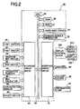
- Fig. 2 is a block diagram schematically showing an electrical construction of the gaming machine shown in Fig. 1.
- the above mentioned 1-BET switch 20, 3-BET switch 22 and maximum BET switch 24 are connected to an interface circuit group 62 of the main control circuit 60, and the interface circuit group 62 is connected to a input / output bus 64.
- Each of the switches produces a predetermined signal when pressed and outputs such signal to the input / output bus 64.
- the operation portion 42 having a plurality of push buttons and the cross key and the spin switch 25 for starting the game are connected to the interface circuit group 62 of the main control circuit 60.
- Each of the operation portion 42 and the spin switch 25 produces a predetermined signal when pressed respectively and outputs such signal to the input / output bus 64.
- the input / output bus 64 is constructed so as to be able to input and output data signals or address signals.
- a CPU 66 conducts transmission and reception of signals with an external through the bus, the CPU 66 may conduct transmission and reception of signals through ports.
- a bill validator 40 and a coin detection sensor 58 are connected to the above mentioned interface group 62.
- the bill validator 40 produces a signal based on kind and number of bill when a bill is inserted therein and transmits such signal to the interface circuit group 62.
- the coin detection sensor 58 produces signal based on kind and number of coin when coins are inserted in the coin insertion slot 44 and transmits such signal to the interface circuit group 62,
- the payout switch 48 is connected to the above mentioned interface circuit group 62 and when the player presses the payout switch 48 a predetermined signal is output to the input / output bus 64. Based on this signal, coins inserted are paid out to the coin payout opening 52 through a payout device 82 mentioned later.
- ROM 68 and a RAM 70 are connected to the above mentioned input /output bus 64.
- the ROM 68 stores control program for wholly controlling procedures done by the system of the gaming machine 2. Further, the ROM 68 stores initial data for executing the control program and a part of program for conducting display control of the display device 32 and the like.
- the RAM 70 temporarily stores the above program and data, flags as calculation result and process result and values of variables.
- a hard-disc drive 74 is also connected to the input / output bus 64, and programs for conducting games and various data such as image data are stored in the hard-disc drive 74.
- a non-volatile memory such as a flash memory which has comparatively large memory capacity, or a volatile memory may be utilized.
- a random number generator 78 for generating random numbers is connected to the input / output bus 64.
- the random number generator 78 When a command to generate random numbers is input to the random number generator 78 from the CPU 66, the random number generator 78 generates random numbers within a predetermined range and outputs a signal indicating the value of random number to the input / output bus 64. And the CPU 66 progresses the game according to the generated random number. Further, such random number is stored in the RAM 70 as the data indicating a lottery result.
- the random number generator 78 may be realized, for example, by software through the program stored in the ROM 68 and the RAM 70.
- an interface circuit group 72 is connected to the input / output bus 64.
- a speaker 80, an information lamp 56 and a payout device 82 are connected to the interface circuit group 72 and the interface circuit group 72 provides drive signals and drive power to control each of the above mentioned devices, based on a result of calculation process done in the CPU 66.
- the information lamp 56 is turned on or Minted when abnormality of the gaming machine 2 is detected and the player calls the shop keeper of the game arcade, thereby the information lamp 56 informs the shop keeper of occurrence of abnormality in the gaming machine 2.
- the information lamp 56 for example, LED, lamp or fluorescent lamp may be utilized.
- a display control device 200 is also connected to the interface circuit group 72 and the display control device 200 produces a drive signal to drive the display device 32 (upper display device 32U and lower display device 32D) connected to the display control device 200, based on an image instruction signal output from the main control circuit 60.
- Fig. 3 is a block diagram showing a construction of the display control device 200 provided in the gaming machine 2 shown in Fig. 1.
- An interface circuit 202 is connected to an input / output bus 204 and an image display command output from the above mentioned main control circuit 60 is input to the input / output bus 204 through the interface circuit 202.
- Data signal and address signal are input to and output from a CPU 206 through the input / output bus 204.
- the CPU 206 may conduct transmission and reception of signals through ports.
- a ROM 208 and a RAM 210 are also connected.
- the ROM 208 stores display control program to produce a drive signal provided to the display device 32 (upper display device 32U and lower display device 32D); .based on image display command output from the main control circuit 60.
- the RAM 210 stores Rags used in the display control program and values of variables.
- an image data processor (abbreviated as VDP hereinafter) 212 is also connected to the input / output bus 204.
- the VDP 212 includes a splite circuit, a screen circuit and a palette circuit, thus the VDP 212 is a processing device capable of conducting various processes to display images on the display device 32 (upper display device 32U and lower display device 32D).
- VDP 212 it is connected a video RAM 214 for storing various image data corresponding to the image display command output from the main control circuit 60 and an image data ROM 216 for storing various image data necessary to conduct the first game and the second game. Further, to the VDP 212, it is connected a drive circuit 218 for producing a drive signal to drive the display device 32 (upper display device 32U and lower display device 32D).
- the above mentioned CPU 206 reads the display control program stored in the ROM 208 and executes it, and stores in the video RAM 214 the image data displayed on the display device 32 (upper display device 32U and lower display device 32D) corresponding to the image display command output from the main control circuit 60. And the image data stored in the video RAM 214 are output to the display device 32 (upper display device 32U and lower display device 32D) through the drive circuit 218.
- the electrical construction of the gaming machine 2 according to the present invention is not limited to examples shown in Figs. 3 and 4.
- FIG. 4 A sub-routine executed by the main control circuit 60 to control the gaming machine 2 is shown in Figs. 4 to 6.
- the gaming machine 2 is operated beforehand and variables used in the mentioned CPU 66 is initialized to a predetermined values and the gaming machine 2 normally operates.
- Fig. 4 is a flowchart showing a sub-routine for conducting the first game process executed in the main control circuit 60.
- This sub-routine is a sub-routine called out and executed at a predetermined timing by a main routine which is executed beforehand.
- step S11 it is determined whether or not coins are betted.
- the CPU 66 determines whether or not a signal indicating that the player conducts BET process is received. If it is determined that such signal is received, the procedure shifts to step S12, and on the other hand, if it is determined that such signal is not received, the sub-routine is terminated.
- the above BET process may be automatically done when the player inserts coins, and may be first done when the player presses any one of the 1-BET switch 20, the 3-BET switch 22 and the maximum BET switch 24.
- step S12 it is determined whether or not the spin switch 26 to instruct game start is pressed.
- the CPU 66 determines whether or not a signal indicating that the player presses the spin switch 25 is received. If it is determined that such signal is received, the procedure shifts to step S13, and on the other hand, if it is determined that such signal is not received, the process in step S12 is executed again.
- step S13 an internal lottery process is conducted (step S13).
- the CPU 66 produces a command indicating that random numbers should be generated by the random number generator 78 and the random number generator 78 generates random numbers based on the above command.
- the CPU 66 stores in a predetermined area in the RAM 70 internal lottery data determined based on the random number obtained.
- the internal lottery data include data indicating a symbol combination mode which can be stopped and displayed if the "big prize” or "small prize” is won. And hereinafter explanation will be done supposed that the probability to win the "big prize” is 1/512, the probability to win the "small prize” is 3/512 and the probability to lose prize (including "obtainment of the second game”) is 508/512.
- random numbers may be produced according to the software by the CPU 66, the program stored in the ROM 68 and the RAM 70 (for example, by renewing a value with a constant frequency or irregular frequency) and the internal lottery data may be stored in the predetermined area in the RAM 70 based on the obtained random number.
- the random number generator 78 can be omitted.
- step S14 rotation and display process of the reels is done (step S14).
- the CPU 66 transmits signals to the display control device 200 so that the game similar to the slot machine is started on the upper display device 32U, that is, the reels displayed on the upper display device 32U as images are rotated.
- symbol image data to determine the symbol combination when stopped based on the above internal lottery data are included.
- the display control device 200 displays the reels so that the reels are rotated on the upper display device 32U, based on the above signals, thereby variable display of the plural symbols is started.
- the display control device 200 also executes display process of various effect images on the lower display device 32D, based on the signals transmitted from the CPU 66.
- step S15 stop display process of the reels is done (step S15).
- the CPU 66 transmits the signal to the display control device 200 so that the game similar to the slot machine is terminated on the upper display device 32U, that is, rotation of the reels displayed on the upper display device 32U as images is stopped.
- the display control device 200 conducts variable display of the plural symbols for a predetermined time, thereafter stops the symbols.
- step S16 winning process in the first game is conducted.
- the CPU 66 executes the winning process based on the symbols stopped or the internal lottery data. This winning process will be described hereinafter.
- the sub-routine is terminated.
- Fig. 5 is a flowchart showing a sub-routine for conducting the winning process in the first game executed by the main control circuit 60.
- This sub-routine is a sub-routine which called out in step S16 in the above mentioned sub-routine shown in Fig. 4, and is executed.
- step S21 it is determined whether or not any one of the symbols stopped and displayed is the symbol to shift to the second game ("7" symbol) (step S21).
- the CPU 66 determines whether or not the symbol to shift to the second game is included among the symbols stopped and displayed in step S 15 of the sub-routine shown in Fig. 4.
- the main control circuit 60 functions as a determination device for determining whether or not the symbol to shift to the second game is included among plural symbols stopped and displayed in the first game.
- the CPU 66 executes the second game process (step S22).
- the second game variable display of the symbols substantially similar to game contents of the first game is done.
- the second game can be done without newly inserting coins and if any one of plural symbols stopped and displayed in the second game coincides with an ANY symbol (for example, "cherry” symbol, "melon” symbol and the like), which is a specific symbol, game worth (coins) corresponding to the kind of ANY symbol is paid out.
- the second game may be executed when coins are inserted. The second game will be explained in detail hereinafter.
- step 521 if it is determined that the symbol to shift to the second game is not included in the symbols stopped and displayed, it is continuously determined whether or not the symbols or the symbol combination is the winning state of the prize (the state that the big prize or the small prize is won)(step S23). And if it is determined that the symbols or the symbol combination stopped and displayed is the winning state of the prize, the CPU 66 drives the payout device 82. That is to say, the CPU 66 drives the payout device 82 so that coins the number of which corresponds to the winning state are paid out to the coin receiving tray 54 through the coin payout opening 52 (step S24), for example so that 1000 coins are paid out if the winning state is the big prize and 500 coins are paid out if the winning state is the small prize.
- step S23 if it is determined that the symbols or the symbol combination is not the winning state of the prize, or if the process in step S22 or step S24 is executed, the sub-routine is terminated.
- the main control circuit 60 functions as the first game controller.
- Fig. 6 is a flowchart showing a sub-routine for conducting the second game process executed by the main control circuit 60.
- This sub-routine is a sub-routine called out and executed in step S22 in the sub-routine shown in Fig. 5.
- the CPU 66 conducts the process to determine the number of kind of ANY symbol (SIL10).
- the number of kind of ANY symbol displayed during the variable display game is determined corresponding to the number of symbol to shift to the second game, the symbol being included in plural symbols stopped and displayed in the first game.
- the process of step s110 is, for example, done based on the ANY symbol determination table shown in Fig. 7.
- Fig. 7 is an explanatory view showing one example of the ANY symbol determination table which is utilized in step S110 of the sub-routine shown in Fig. 6.
- the probability that the ANY symbol shown in Fig. 7 is included in the symbols stopped and displayed is set to 100/512 in all kinds of ANY symbols.
- the probability to win the "big prize” is set to 1/512 and the probability to win the "small prize” is set to 3/512.
- the ANY symbol displayed in the second game is "cherry” symbol. At that time, if any one of the symbols stopped and displayed in the second game is the "cherry” symbol, 100 coins are paid out. And for example, if the "number of symbol to shift to the second game” is "2", the ANY symbol displayed in the second game is the "cherry” symbol and “melon” symbol. At that time, if any one of the symbols stopped and displayed in the second game is the "cherry” symbol, 100 coins are paid out, and if any one of the symbols stopped and displayed in the second game is the "melon” symbol, 200 coins are paid out.
- the probability that the ALL symbol is included in the symbols stopped and displayed in the second game is set to 100/512 in all kinds of ALL symbols, therefore according that the "number of symbol to shift to the second game" included in the symbols stopped and displayed in the first game increases and the kind of ANY symbol displayed in the second game increases, the probability that any one of the symbols stopped and displayed coincides with the ANY symbol becomes high.
- step S110 it is continuously determined whether or not the spin switch 25 to instruct game start is pressed (step S112).
- the CPU 66 determines whether or not a signal indicating that the spin switch 25 is pressed by the player is received. If it is determined that such signal is received, the procedure shifts to S113, and on the other hand, if it is determined that such signal is not received, the process in step S112 is executed again.
- step S113 the internal lottery process is conducted (step S113).
- the CPU 66 transmits a command to generate the random numbers to the random number generator 78 and the random number generator 78 which receives the above command generates the random numbers. Further, the CPU 66 stores in the predetermined area in the RAM 70 the internal lottery data calculated based on the obtained random number.
- step S114 rotation process of the reels is done (step S114).
- the CPU 66 transmits a signal to the display control device 200 so that the game like the slot machine is started on the upper display device 32U, that is, the reels displayed as images on the upper display device 32U are rotated.
- Such signal includes the symbol image data for determining the symbol combination when stopped and displayed based on the above internal lottery data.
- the display control device 200 controls the upper display device 32U so that the reels are rotated on the upper display device 32U, thereby variable display of plural symbols is started.
- the display control device 200 also conducts the process in which various effect images are displayed on the lower display device 32D based on the signal transmitted from the CPU 66.
- step S115 stop display process of the reels is conducted (step S115).
- the CPU 66 transmits a signal to the display control device 200 so that the game like the slot machine is terminated, that is, rotation of the reels displayed as images on the upper display device is stopped.
- the display control device 200 conducts variable display of plural symbols for a predetermined time, thereafter stops and displays plural symbols.
- step S115 the CPU 66 continuously conducts the winning process in the second game (5116). In this process, the CPU 66 conducts the winning process based on the symbol stopped and displayed or the internal lottery data. This process will be described hereinafter. After the process in step S116, the sub-routine is terminated.
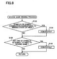
- Fig. 8 is a flowchart showing a sub-routine for conducting the winning process in the second game executed by the main control circuit 60.
- This sub-routine is a sub-routine which called out in step S116 in the above mentioned sub-routine shown in Fig. 6, and is executed.
- step S123 it is determined whether or not the symbols or the symbol combination stopped and displayed corresponds to the winning state of prize ("big prize” or "small prize”) (step S123). And if it is determined that the symbols or the symbol combination corresponds to the winning state of prize, the CPU 66 drives the payout device 82. That is to say, the CPU 66 drives the payout device 82 so that coins the number of which corresponds to the winning state are paid out to the coin receiving tray 54 through the coin payout opening 52 (step S124), for example so that 1000 coins are paid out if the winning state is the big prize and 500 coins are paid out if the winning state is the small prize.
- step 5123 if it is determined that the symbols or the symbol combination does not correspond to the winning state of prize, the CPU 66 continuously determines whether or not any one of the symbols stopped and displayed coincides with the ANY symbol (step S125). If it is determined that any one of the symbols stopped and displayed. coincides with the ANY symbol, the CPU 66 conducts the process to pay out coins the number of which corresponds to the kind of ANY symbol to the coin receiving tray 54 through the coin payout opening 52 (step S126).
- step S126 After the process of step S126 is executed or if it is determined that any one of the symbols stopped and displayed in step S125 does not coincide with the ANY symbol, the sub-routine is terminated.
- the main control circuit 60 functions as the second game controller.
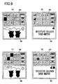
- Figs. 9 (a) ⁇ (d) are explanatory views schematically showing images displayed on the upper display device 32U and the lower display device 32D when the sub-routines shown in Figs. 4 ⁇ 8 are executed.
- Fig. 9 (a) show an example of images displayed on the display device 32 right after the first game is terminated.
- the image showing a game like the slot machine having five (5) reels and nine (9) pay lines is displayed.
- the symbol to shift to the second game (“7" symbol) is stopped and displayed in the left reel.
- the effect image is displayed.
- the effect image displayed on the lower display device 32D includes the image indicating while the second game called “bonus game” is executed. And at the right side thereof, it is displayed the image indicating that the "cherry” symbol as the ANY symbol is activated. Further, at the lower position of the image indicating the "bonus game”, it is displayed the image indicating that the "cherry” symbol is included in the symbols stopped and displayed on the upper display device 32U and game worth of 100 coins is paid out based on that the "cherry" prize is won.
- the images shown in Fig. 9 (c) show an example of images displayed on the display device 32 right after the first game is terminated.
- the image showing a game like the slot machine having five (5) reels and nine (9) pay lines is displayed.
- the symbol to shift to the second game (“7" symbol) are stopped and displayed.
- the effect image is displayed.
- the effect image displayed on the lower display device 32D includes the image indicating while the second game called “bonus game” is executed. Further, at the right side thereof, it is displayed the image indicating that the "cherry” symbol and the “melon” symbol as the ANY symbol are activated. Further, at the lower position of the image indicating the "bonus game”, it is displayed the image indicating that the "melon” symbol is included in the symbols stopped and displayed on the upper display device 32U and game worth of 200 coins is paid out based on that the "melon" prize is won.
- the game similar to the first game in which variable display of plural symbols is done, when seeing from outside, is conducted as the second game and the ANY symbol is included in the symbols variably displayed in the second game. And if any one of the symbols stopped and displayed coincides with the ANY symbol, game worth (coins) is paid out.
- the second game has game contents different from those in the first game while retaining connection with the first game. Therefore, feelings capable of enjoying one game with two ways can be given to the player, as a result, interest for games can be raised.
- the present invention it is not necessary to determine the number of kind of the specific symbol (for example, ANY symbol) displayed during variable display in the second game corresponding to only the number of predetermined symbol (for example, symbol to shift to the second game) included in the symbols stopped and displayed in the first game.
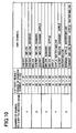
- the lottery is conducted in step S110 (ANY symbol determination process) of the sub-routine shown in Fig. 6 while referring the ANY symbol determination table shown in Fig. 10, and the number of kind of the ANY symbol displayed in the second game can be determined corresponding to the lottery result and the number of symbol to shift to the second game included in the symbols stopped and displayed in the first game.
- Fig. 10 is an explanatory view schematically showing another example of the ANY symbol determination table which is utilized in step 5110 of the sub-routine shown in Fig. 6.
- the probability that the ANY symbol shown in Fig. 10 is included in any of the symbols stopped and displayed is set to 100/512 in all plural kinds of ANY symbols.
- the "number of symbol to shift to the second game" in the most left column indicates the number of symbol to shift to the second game included in the symbols stopped and displayed in the first game.
- the "lottery result” indicates a random number range extracted in the lottery. Here, one random number is extracted in a random number range of 0 ⁇ 63 in the above lottery.
- the "ANY symbol” in the most right column of the table indicates the number of kind of the ANY symbol displayed during variable display in the second game.
- the ANY symbol displayed during variable display in the second game is "cherry”.
- the "number of symbol to shift to the second game” is "2” and the lottery result is "50”
- the ANY symbols displayed during variable display in the second game are "cherry”, “melon”, “banana” and "apple”.
- the number of kind of the ANY symbol is not determined corresponding to only the number of symbol to shift to the second game, but is determined corresponding to both the number of symbol to shift to the second game and the lottery result obtained by the lottery done thereafter. Thereby, determination of the number of the ANY symbol displayed can be further variegated, as a result, interest for games can be improved.
- the number of the specific symbol converted in the second game may be determined.
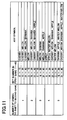
- a ANY symbol determination table shown in Fig. 11 is referred and the number of the ANY symbol may be determined corresponding to both the number of the symbol to shift to the second game, such symbol being included in the symbols stopped and displayed in the first game, and the number of game worth (coins) betted in the first game.
- Fig. 11 is further another explanatory view showing one example of a ANY symbol determination table which is utilized in S110 in the sub-routine shown in Fig. 6.
- the probability that the ANY symbol shown in Fig. 11 is included in any of the symbols stopped and displayed is set to 100/512 in all plural kinds of ANY symbols.
- the "number of symbol to shift to the second game" in the most left column indicates the number of symbol to shift to the second game included in the symbols stopped and displayed in the first game.
- the "bet number in the first game” indicates a range of number of game worth (coins) betted in the first game.
- the game worth (coins) in a range of 1 ⁇ 45 can be utilized.
- the game worth (coins) within a range of 1 ⁇ 45 can be utilized in the first game.
- the "bet number” in Fig. 11 indicates a total bet number betted in the first game.
- the ANY symbol displayed during variable display in the second game is "cherry”.
- the ANY symbols displayed during variable display in the second game are "cherry”, “melon”, “banana” and "apple”.
- the number of kind of the ANY symbol displayed in the second game is not determined corresponding to only the number of symbol to shift to the second game, but is determined corresponding to both the number of symbol to shift to the second game and the number of game worth (coins) betted in the first game.
- determination of the number of the ANY symbol displayed in the second game can be further variegated.
- the player can change the number of kind of the ANY symbol displayed in the second game according to his or her own intention, by increasing or decreasing the game worth (coins) betted in the first game, thereby strategy can be given to the second game.
- the number of the specific symbol displayed in the second game may be determined corresponding to the number of the predetermined symbol included in the symbols stopped and displayed in the first game.
- the same symbol for example, "7" symbol
- the predetermined symbol for example, symbol to shift to the second game
- the specific symbol for example, ANY symbol
- the present invention may be adopted to the slot machine mentioned hereinafter.
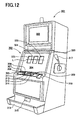
- Fig. 12 is a perspective view of a slot machine as another gaming machine according to the present invention.
- the slot machine 301 has a cabinet 302 constructing a whole of the slot machine 301.
- an upper liquid crystal display 303 is arranged, and at a front central part of the cabinet 302 a lower liquid crystal display 304 is arranged.
- the upper liquid crystal display 303 is constructed from a liquid crystal display device which is generally used, and the lower liquid crystal display 304 is constructed from, so-called, a transparent liquid crystal display device. A detailed construction of the transparent liquid crystal display device will be, explained hereinafter.
- An operation table 305 which is projected frontward, is formed below the lower liquid crystal display 304, and from the most left side on the operation table 305, a change button 306, a payout (cash out) button 307, a help button 308 are arranged. And a coin insertion slot 309 and a bill insertion portion 310 are arranged at the right side of the help button 308. Further, from the left side, a 1-BET button 311, a SPIN/REPEAT BET button (hereinafter, abbreviated as "spin button”) 312, a 3-BET button 313 and a 5-BET button 314 are positioned at the front side on the operation table 305.
- spin button SPIN/REPEAT BET button
- the change button 306 is pressed when exchanging the bill inserted in the bill insertion portion 311, and the exchanged coins are paid out through a coin payout opening 315 to a coin tray 316 which is formed at the lower part of the cabinet 302.
- a change switch 362 (explained hereinafter) is attached, and the a switch signal is output to a CPU 350 (mentioned hereinafter) from the change switch 362 based on press of the change button 306.
- the payout button 307 is usually pressed when games are terminated, and when the payout button 307 is pressed coins got in games are paid out through the coin payout opening 315 to the coin tray 316.
- a payout (cash out) switch 363 (mentioned hereinafter) is attached and a switch signal is output to the CPU 350 from the payout switch 363 based on press of the payout button 307.
- the help button 308 is pressed when the player cannot understand game operation method, and when the help button 308 is pressed, various help information is displayed on the upper liquid crystal display 303 or the lower liquid crystal display 304.
- a help switch 364 (mentioned hereinafter) is attached and a switch signal is output to the CPU 350 from the help switch 364 based on press of the help button 308.
- a coin sensor 365 (mentioned hereinafter) is positioned, and when the coin is inserted in the coin insertion slot 309 a coin detection signal is output to the CPU 350 through the coin sensor 365.
- a bill sensor 366 (mentioned hereinafter) is positioned, and when the bill is inserted in the bill insertion portion 310 a bill detection signal is output to the CPU 350 through the bill sensor 366.
- the 1-BET button 31 As for the 1-BET button 311, every the 1-BET button 311 is pressed one credit is betted, and the 1-BET button 311 can bet by pressing up to tree times as the maximum pressing time. To the 1-BET button 311, a 1-BET switch 359 is attached and when the 1-BET button 311 is pressed a switch signal is output to the CPU 350 from the 1-BET switch 359 based on press of the 1-BET button 311.
- the spin button 312 is the button to start games from the present bet number or the previous bet number by press thereof, thereby reels 322 (mentioned later) are started to rotate.
- a spin switch 358 (mentioned later) is attached, and when the spin button 312 is pressed a switch signal is output to the CPU 350 from the spin switch 358 based on press of the spin button 312.
- the bet number which can be betted by press of the spin button 312 there may exist 1, 2, 3 and 5 bets.
- the 3-BET button 313 is the button to start games from 3 bets on the basis of press thereof.
- a 3-BET switch 360 (mentioned hereinafter) is attached and when the 3-BET button 313 is pressed a switch signal is output to the CPU 350 from the 3-BET switch 360.
- the 5-BET button 314 is the button to start games from 5 bets on the basis of press thereof.
- a 5-BET switch 361 is attached and when the 5-BET button is pressed a switch signal is output to the CPU 350 from the 5-BET switch 361 on the basis of press thereof.
- the coin payout opening 315 is formed and the coin tray 316 to receive coins paid out from the coin payout opening 315 is provided.
- a coin detection part 373 constructed from a sensor and the like is positioned and the coin detection part 373 detects number of coins paid out from the coin payout opening 315.
- a start lever 317 is arranged rotatably within a predetermined angle range.
- a start switch 357 is attached to the start lever 317 and when the start lever 317 is rotated a switch signal occurring from the start switch 357 is output to the CPU 350.
- Fig. 13 is a longitudinal sectional view of the lower liquid crystal display 304 and the reels 322, and Fig. 14 is an exploded perspective view of the lower liquid crystal display 304.
- the lower liquid crystal display 304 is arranged within a display window 321 of a device front panel 320 positioned at the front center part of the cabinet 302 in the slot machine 301, with a transparent touch panel 330 (abbreviated as "touch panel 330" hereinafter), arranged at the front side (the left side in Fig. 13) of the lower liquid crystal display 304. And at the rear side (the right side in Fig. 13) of the lower liquid crystal display 304, three reels 322 (only one reel 322 is indicated in Fig. 13) are supported in a parallel state so that the reels 322 become independently rotatable.
- a transparent touch panel 330 abbreviated as "touch panel 330" hereinafter
- each reel 322 will be described.
- the left reel 322 when seeing the front plane of the slot machine 301 faces to a left display window 323 (see Fig. 12) formed in the lower liquid crystal display 304
- the center reel 322 faces to a center display window 324 (see Fig. 12) similarly formed in the lower liquid crystal display 304
- the right reel 322 faces to a right display window 325 (see Fig. 12) similarly formed in the lower liquid crystal display 304. Construction of each of the display windows 323, 324, 325 will described hereinafter.
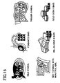
- each reel 322 various kinds of symbols shown in Fig. 15 (6 kinds of symbols are indicated in Fig. 15) are formed.
- symbols formed on the outer periphery of the reel 322 concerning with game contents conducted in the slot machine 301, it is utilized a wild symbol a pendant symbol, a trigger symbol, a red 7 symbol to which a beautiful girl is attached, a bill bundle symbol and a gold coin symbol.
- these 6 kinds of symbols and blank (a) are combined based on a predetermined combination and the combinations in which the symbols and the blanks are totally combined (the total number of the symbols and the blanks is 22) is formed.
- such combination with of symbols and blanks total number of which is 22 is formed.
- the pay line L is determined to only the center line, and such pay line L is displayed on the lower liquid crystal display 304 when the game, namely the first game, is conducted by rotating and stopping the reels 322 based on press of the spin button 312, the 3-BET button 313 and the 5-BET button 314 or rotation of the start lever 317.
- the above mentioned trigger symbol functions as a trigger to obtain the second games.
- one trigger symbol is formed only on the peripheral plane of the right reel 322. Based on that the trigger symbol existing on the peripheral plane of the right reel 322 is stopped on the pay line L in the first game, the second game can be obtained.
- the specific condition to execute the second game is that the trigger symbol stops on the pay line L.
- the lower liquid crystal display 304 is constructed by arranging from the front side of the slot machine 301; the touch panel 330, the reel glass base 331, the bezel metal frame 332, the transparent liquid crystal panel 333, the liquid crystal holder 334, the scattering sheet 335, the light leading plate 336, the white reflector 337, the rear holder 338 and the antistatic sheet 339.
- the scattering sheet 335 three openings 335A, 335B, 335C are formed.
- openings 336A, 336B, 336C, 337A, 337B, 337C, 338 A, 338B, 338C are formed respectively, so as to coincide with the openings 335A, 335B, 335C.
- the openings 335A ⁇ 338A construct the left display window 323 (see Fig. 12) by superimposing so as to coincide with each other.
- the openings 335B ⁇ 338B construct the center display window 324 (see Fig. 12) by superimposing so as to coincide with each other
- the openings 335C ⁇ 338C construct the right display window 325 (see Fig. 12) by superimposing so as to coincide with each other.
- the openings 335A ⁇ 335C in the scattering sheet 335 and the openings 336A ⁇ 336C in the light leading plate 336 construct the light transmitting areas to retain visibility while variable displaying is conducted by rotating reels 322.
- brackets 340 are screwed to the rear side of the device front panel 320 by screws 341.
- a pair of cold cathode ray tubes 342 are arranged as light sources of the liquid crystal panel 333.
- a pair of cold cathode ray tubes 343 are arranged to illuminate the symbols on the outer periphery of each of the reels 322.
- the liquid crystal panel 333 is a transparent electric display panel on which transparent electrodes such as ITO are formed, and arranged in front of each of the reels 322 which can be seen therethrough. And the circumference in rear aide of the display part of the liquid crystal panel 333 is held by the liquid crystal holder 334.
- the light leading plate 336 is made from the light transmitting resin panel, and in the light leading plate 336 lens cut portions are formed, the lens cut portions leading light emitted from the cold cathode ray tubes 343 positioned at side positions to the rear side of the liquid crystal panel 333.
- the light scattering sheet 335 is made from a light transmitting resin sheet and scatters light led by the light leading panel 336 and levels light irradiated to the liquid crystal panel 333.
- the liquid crystal holder 334 for holding the liquid crystal panel 333, the scattering sheet 335 and the light leading plate 336 are assembled into one body and circumference thereof is inserted in the bezel metal frame 332. Thereby, the front side of the display part in the liquid crystal panel 333 is retained by the bezel metal frame 332.
- the transparent touch panel 330 is pressed and contacted to the front side of the reel glass base 331 by installing the reel glass base 331 to the device front panel 320 through the screws 341, thereby the transparent touch panel 330 is superimposed on the front display plane of the liquid crystal panel 333.
- the rear holder 338 is made from a white resin plate and retains to the reel glass base 331 the bezel metal frame 332 supported to the reel glass base 331, the liquid crystal holder 334 holding the liquid crystal panel 333, the light scattering sheet 335 and the light leading plate 336 from the rear sides thereof.
- the rear holder 338 also functions as a reflecting plate for reflecting light emitted from the cold cathode ray tubes 343 to the light leading plate 336 toward the liquid crystal panel 333.
- the antistatic sheet 339 is made transparent and adhered to the rear plane of the rear holder 338 by double-sided adhesive tape, thereby the antistatic sheet 339 covers the rear plane of each of the openings 338A ⁇ 338C formed in the rear holder 338.
- Fig. 16 is a block diagram schematically showing the control system in the slot machine 301.
- the control system of the slot machine 301 is basically constructed from the CPU 350, and a ROM 351 and a RAM 352 arc connected to the CPU 350.
- the ROM 351 stores game control program (mentioned later), various effect programs for executing various effects on the upper liquid crystal display 303 and the lower liquid crystal display 304 according to progress in games, lottery program for conducting lottery of various winning combinations, various programs necessary for controlling the slot machine 301 and various data tables and the like.
- the RAM 352 is a memory for temporarily storing various data calculated by the CPU 350.
- the CPU 350 executes the first game based on the various programs stored in the ROM 351 and the second game when the specific condition is realized in the first game.
- a clock pulse generator 353 for generating standard clock pulses and a frequency divider 354 are connected, and a random number generator 355 and a sampling circuit 356 are also connected. Random number sampled by the random number generator 356 is utilized in various lotteries of the symbol every each reel 322, the effects and the like.
- the symbol stopped on the pay line L are determined as follows. That is, a random number range corresponding to the symbols every each reel 322 is set beforehand and the random number every each reel 322 extracted from a predetermined random number range (for example, the range of "0" ⁇ "255") and the "probability lottery table" (not shown) are referred with each other.
- the symbols are determined by determining that the extracted random number lies in the random number range of which symbol.
- the start switch 357 attached to the start lever 317, the spin switch 358 attached to the spin button 312, the 1-BET switch 359 attached to the 1-BET button 311, the 3-BET switch 360 attached to the 1-BET button 313, the change switch 362 attached to the change button 306, the cashout switch 363 attached to the cashout button 307 and the help switch 364 attached to the help button 308 are connected respectively.
- the CPU 350 controls the slot machine 301 to execute various operations corresponding to each button, based on the switch signal output from each switch when such buttons are pressed.
- the coin sensor 365 positioned in the coin insertion slot 309 and the bill sensor 366 positioned in the bill insertion portion 310 are connected respectively.
- the coin sensor 365 detects coins inserted from the coin insertion slat 309 and the CPU 350 calculates the number of inserted coins based on the coin detection signal output from the coin sensor 365.
- the bill sensor 366 detects the kind and sum of bill and the CPU 350 calculates the number of coins equivalent to sum of bill, based on the bill detection signal output from the bill sensor 366.
- each stepping motor 368 for rotating each of the reels 322 through a motor drive circuit 367 are connected, and also a reel position detection circuit 369 is connected.
- a motor drive signal is output to the motor drive circuit 367, each stepping motor 368 is driven to rotate by the motor drive circuit 367, thereby each reel 322 is rotated.
- the number of drive pulses provided to each stepping motor 368 is calculated and the calculated value is written in the predetermined area of the RAM 352.
- the reset pulse is output every one rotation of the reel 322 and such reset pulse is input to the CPU 350 through the reel position detection circuit 369.
- the CPU 350 recognizes the symbol rotational position in the reel 322, based on the calculated value corresponding to the rotational position of the reel 322 within one rotation and the symbol table in which the rotational position of the reel 322 stored in the ROM 351 and the symbols formed on outer peripheral plane of the reel 322 are corresponded with each other.
- a hopper 371 is connected through a hopper drive circuit 370.
- the hopper 371 pays out predetermined number of coins from the coin payout opening 315.
- a coin detection part 373 is connected through a payout completion signal circuit 372.
- the coin detection part 373 is arranged in the coin payout opening 315 and when the coin detection part 373 detects that a predetermined number of coins are paid out from the coin payout opening 315, the payout completion signal is output to the payout completion signal circuit 372 from the coin detection part 373. Based on this, the payout completion signal circuit 372 outputs the payout completion signal to the CPU 350.
- the upper liquid crystal display 303 is connected through a liquid crystal drive circuit 374 and the lower liquid crystal display 304 is connected through a liquid crystal drive circuit 375.
- the touch panel 330 is connected through a touch panel drive circuit 376.
- LEDs 378 are connected through a LED drive circuit 377.
- a plurality of the LEDs 378 are arranged on the front plane of the slot machine 301 and the LEDs 378 are controlled so as to turn on based on the drive signals from the CPU 350.
- a speaker 380 and a sound output circuit 379 are connected to the CPU 350 and the speaker 380 produces various effective sounds when various effects are conducted based on the output signal from the sound output circuit 379.
- a progressive interface (1/F) 381 is provided to the CPU 350.
- the player can see and recognize the symbols, which are variably displayed and stopped and displayed, through the lower liquid crystal display 304 which is the so-called transparent liquid crystal display.
- the second game is executed.
- the game contents of the second game itself is as same as those of the first game and the game contents of the first game are already explained, thus explanation of the second game will omitted.
- the second game may be executed on the upper display device 303 or the lower display device 304. Further, the second game may be executed on each of the upper display device 303 and the lower display device 304.
- the second game may be executed on three reels 322, the lower liquid crystal display 303 and the lower liquid crystal display 304.
- the specific symbols can be displayed on the lower liquid crystal display 304 so as to cover the symbols formed on the reels 322.
- the game worth (for example, coins) paid out to the player may be determined based on the number of coins betted in the first game and the point number obtained in the second game, as in the gaming machine 2.
- the common bonus so-called progressive bonus
- the game worth as the common bonus may be paid out from the slot machine 301 in which the points more than a predetermined number are obtained in the second game.
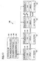
- Fig. 17 is an explanatory view schematically showing the progressive gaming system.
- a plurality of slot machines 301 are connected to a transmission control part 384 in the progressive unit 383 through the progressive interface (I/F) 381 provided in each slot machine 301.
- I/F progressive interface
- any one of wire connection and wireless connection can be utilized. Thereby, mutual transmission can be done through the transmission control part 384 between the progressive unit 383 and each slot machine 301.
- Such pool number information of coins is transmitted from the progressive unit 383 to each slot machine 301 through the transmission control part 384 and displayed on the upper liquid crystal display 303 in each slot machine 301. And a pool number calculation part 385 in the progressive unit 383 adds the common bonus based on the coin insertion information transmitted from each slot machine 301.
- the coin number corresponding to the common bonus won is rest to the initial number of coins.
- the pool number storing part 386 stores the above mentioned coin number calculated by the pool number calculation part 385.
- the progressive unit 383 constructed according to the above periodically transmits from the transmission control part 384 to each slot machine 301 the coin pool number information stored in the pool number storing part 386. And each slot machine 301 periodically compares the coin pool number information transmitted in previous time with the coin pool number information transmitted in present time, based on the coin pool number information transmitted from the progressive unit 383. And in a case that the coin pool number in present time reduces than the coin pool number in previous time, each slot machine 301 notifies that the common bonus in which the coin pool number reduces is won.
- the predetermined winning state such as the "big prize” or the "small prize”
- the game worth for example, coins
- the common bonus accumulated from a plurality of slot machines 301 can be obtained. Therefore, it concludes that competitive spirit of the other players is stirred up, as a result, interest and connection for the second game can be raised.
- the number of the predetermined symbol included in the symbols stopped and displayed in the first game the number of the specific symbol displayed in the second game is determined and the second game result is affected by the number of the specific symbol. Therefore, interest and connection for not only the second game but also the first game can be raised, thus interest for games can be improved.
Landscapes
- Physics & Mathematics (AREA)
- General Physics & Mathematics (AREA)
- Slot Machines And Peripheral Devices (AREA)
- Display Devices Of Pinball Game Machines (AREA)
- Pinball Game Machines (AREA)
- Game Rules And Presentations Of Slot Machines (AREA)
Abstract
Description
Claims (8)
- A gaming machine comprising:wherein the second game controller controls the display device so that a specific symbol characterizing the second game is displayed on the second display area and controls the payout device to pay out the game medium when any one of the symbols stopped and displayed on the first display area in the second game coincides with the specific symbol.a display device with a first display area and a second display area;a first game controller for executing a first game in which symbols are scrolled in each of plural rows on the first display area and a game result in determined corresponding to the symbol or a symbol combination stopped and displayed on the first display area;a first determination device for determining whether or not a predetermined symbol is included in the symbols stopped and displayed in the first game;a second game controller for executing a second game in which the symbols are scrolled in each of plural rows on the first display area when the first determination device determines that the predetermined symbol is included in the symbols stopped and displayed in the first game; anda payout device for paying out a game medium corresponding to a game result in the first game or the second game;
- The gaming machine according to claim 1, further comprising:a second determination device for determining a number of kind of the specific symbol displayed on the second display area in the second game corresponding to a number of the predetermined symbol included in the symbols stopped and displayed on the first display area in the first game.
- The gaming machine according to claim 2, wherein the number of kind of the specific symbol increases according that the number of the predetermined symbol increases.
- The gaming machine according to claim 3, wherein a probability that any one of the symbols stopped and displayed in the second game coincides with the specific symbol increases according that the number of kind of the specific symbol increases.
- The gaming machine according to claim 2, further comprising:wherein the second determination device determines the number of kind of the specific symbol based on the number of the predetermined symbol stopped and displayed in the first game and the random number extracted by the lottery device.a lottery device for conducting a lottery to extract a random number when the number of kind of the specific symbol is determined;
- The gaming machine according to claim 2, further comprising:wherein the second determination device determines the number of kind of the specific symbol based on the number of the predetermined symbol stopped and displayed in the first game and the number of the game medium counted by the count device.a count device for counting a number of the game medium betted in the first game;
- The gaming machine according to claim 1, wherein the display device includes a display on which a plurality of reels each of which has the symbols are displayed so that the reels are rotated and the symbols are scrolled.
- The gaming machine according to claim 1, wherein the display device includes a plurality of reels on each of which the symbols are formed, the reels being rotatably supported, and
wherein the symbols are scrolled by rotating the reels.
Applications Claiming Priority (2)
| Application Number | Priority Date | Filing Date | Title |
|---|---|---|---|
| JP2004022229A JP2005211341A (en) | 2004-01-29 | 2004-01-29 | Game machine |
| JP2004022229 | 2004-01-29 |
Publications (2)
| Publication Number | Publication Date |
|---|---|
| EP1560175A2 true EP1560175A2 (en) | 2005-08-03 |
| EP1560175A3 EP1560175A3 (en) | 2005-10-26 |
Family
ID=34650832
Family Applications (1)
| Application Number | Title | Priority Date | Filing Date |
|---|---|---|---|
| EP05001007A Ceased EP1560175A3 (en) | 2004-01-29 | 2005-01-19 | Gaming machine |
Country Status (7)
| Country | Link |
|---|---|
| US (1) | US20050170879A1 (en) |
| EP (1) | EP1560175A3 (en) |
| JP (1) | JP2005211341A (en) |
| CN (1) | CN1647843A (en) |
| AU (1) | AU2005200347B2 (en) |
| EA (1) | EA007527B1 (en) |
| ZA (1) | ZA200500692B (en) |
Families Citing this family (17)
| Publication number | Priority date | Publication date | Assignee | Title |
|---|---|---|---|---|
| US8083580B2 (en) * | 2001-10-02 | 2011-12-27 | Universal Entertainment Corporation | Slot machine and control method of game |
| JP2004166820A (en) | 2002-11-18 | 2004-06-17 | Aruze Corp | Game machine |
| EP1430938B1 (en) | 2002-11-20 | 2013-01-23 | Universal Entertainment Corporation | Gaming machine and display device therefor |
| JP2004166963A (en) | 2002-11-20 | 2004-06-17 | Aruze Corp | Gaming machine |
| JP2004166962A (en) | 2002-11-20 | 2004-06-17 | Aruze Corp | Game machine |
| US8096867B2 (en) | 2002-11-20 | 2012-01-17 | Universal Entertainment Corporation | Gaming machine and display device with fail-tolerant image displaying |
| US7892094B2 (en) | 2003-05-14 | 2011-02-22 | Universal Entertainment Corporation | Gaming machine with a light guiding plate subjected to a light scattering process and having a light deflection pattern |
| US8231464B2 (en) | 2005-12-19 | 2012-07-31 | Wms Gaming Inc. | Multigame gaming machine with transmissive display |
| JP2008017945A (en) | 2006-07-11 | 2008-01-31 | Aruze Corp | Game machine and game control method |
| US7846019B2 (en) | 2006-08-18 | 2010-12-07 | Aruze Gaming America, Inc. | Slot machine and playing method thereof |
| US20080045306A1 (en) * | 2006-08-18 | 2008-02-21 | Aruze Gaming America, Inc. | Slot machine and playing method thereof |
| US7762882B2 (en) * | 2006-09-05 | 2010-07-27 | Aruze Gaming America, Inc. | Slot machine and playing method thereof |
| AU2008229753A1 (en) * | 2007-10-11 | 2009-04-30 | Aristocrat Technologies Australia Pty Limited | A gaming system and a method of gaming |
| US20090221351A1 (en) * | 2008-02-28 | 2009-09-03 | Aruze Corp. | Gaming Machine |
| US8172666B2 (en) | 2008-04-01 | 2012-05-08 | Aruze Gaming America, Inc. | Slot machine |
| JPWO2015037717A1 (en) * | 2013-09-13 | 2017-03-02 | コナミゲーミング インコーポレーテッド | Gaming machine |
| JP6591734B2 (en) | 2013-09-18 | 2019-10-16 | コナミゲーミング インコーポレーテッド | Gaming machine, gaming machine control method and program |
Family Cites Families (14)
| Publication number | Priority date | Publication date | Assignee | Title |
|---|---|---|---|---|
| US6234897B1 (en) * | 1997-04-23 | 2001-05-22 | Wms Gaming Inc. | Gaming device with variable bonus payout feature |
| US5980384A (en) * | 1997-12-02 | 1999-11-09 | Barrie; Robert P. | Gaming apparatus and method having an integrated first and second game |
| US6190255B1 (en) * | 1998-03-24 | 2001-02-20 | Wms Gaming Inc. | Bonus game for a gaming machine |
| US6159098A (en) * | 1998-09-02 | 2000-12-12 | Wms Gaming Inc. | Dual-award bonus game for a gaming machine |
| AUPP734198A0 (en) * | 1998-11-26 | 1998-12-24 | Aristocrat Leisure Industries Pty Ltd | Player information delivery |
| US6159097A (en) * | 1999-06-30 | 2000-12-12 | Wms Gaming Inc. | Gaming machine with variable probability of obtaining bonus game payouts |
| US20020151360A1 (en) * | 1999-09-10 | 2002-10-17 | Durham Timothy J. | Gaming machine having a controller for controlling multiple displays |
| US6364766B1 (en) * | 2000-08-03 | 2002-04-02 | Wms Gaming Inc. | Gaming machine with sorting feature |
| US6347996B1 (en) * | 2000-09-12 | 2002-02-19 | Wms Gaming Inc. | Gaming machine with concealed image bonus feature |
| US6921335B2 (en) * | 2001-09-28 | 2005-07-26 | Igt | Gaming device having symbols with transformation probabilities |
| US6955600B2 (en) * | 2001-10-15 | 2005-10-18 | Igt | Gaming device having a re-triggering symbol bonus scheme with a bonus symbol accumulator |
| US6964416B2 (en) * | 2001-12-21 | 2005-11-15 | Igt | Method of playing a matching bonus game |
| US7399226B2 (en) * | 2002-09-12 | 2008-07-15 | Igt | Matching symbol game associated with slot machine |
| JP2005211340A (en) * | 2004-01-29 | 2005-08-11 | Aruze Corp | Game machine |
-
2004
- 2004-01-29 JP JP2004022229A patent/JP2005211341A/en active Pending
-
2005
- 2005-01-19 EP EP05001007A patent/EP1560175A3/en not_active Ceased
- 2005-01-24 ZA ZA2005/00692A patent/ZA200500692B/en unknown
- 2005-01-27 US US11/043,309 patent/US20050170879A1/en not_active Abandoned
- 2005-01-28 AU AU2005200347A patent/AU2005200347B2/en not_active Ceased
- 2005-01-28 CN CNA2005100061434A patent/CN1647843A/en active Pending
- 2005-01-28 EA EA200500117A patent/EA007527B1/en not_active IP Right Cessation
Also Published As
| Publication number | Publication date |
|---|---|
| EA007527B1 (en) | 2006-10-27 |
| US20050170879A1 (en) | 2005-08-04 |
| EA200500117A1 (en) | 2005-08-25 |
| ZA200500692B (en) | 2005-09-28 |
| AU2005200347B2 (en) | 2011-06-09 |
| JP2005211341A (en) | 2005-08-11 |
| AU2005200347A1 (en) | 2005-08-18 |
| EP1560175A3 (en) | 2005-10-26 |
| CN1647843A (en) | 2005-08-03 |
Similar Documents
| Publication | Publication Date | Title |
|---|---|---|
| US7510476B2 (en) | Gaming machine with a display controller for alternatively executing an effect and displaying a first game or alternatively executing the effect and a second game | |
| AU2004202718B2 (en) | Gaming machine in which second game can be obtained continuous to first game under predetermined condition | |
| US8337286B2 (en) | Gaming machine with image display assistance feature | |
| US20050049032A1 (en) | Gaming machine | |
| AU2005200347B2 (en) | Gaming machine | |
| US20050079913A1 (en) | Gaming machine | |
| EP1560176A1 (en) | Gaming machine | |
| EP1515284A2 (en) | Gaming machine | |
| US20040235553A1 (en) | Gaming machine and gaming system with a plurality of gaming machines | |
| JP2007054494A (en) | Game machine | |
| EP1589503A1 (en) | Gaming machine | |
| EP1571626B1 (en) | Gaming machine | |
| EP1622103A1 (en) | Gaming machine | |
| US20060287061A1 (en) | Gaming machine | |
| JP2005211502A (en) | Game machine | |
| JP2006305233A (en) | Game machine | |
| ZA200605975B (en) | Gaming machine | |
| JP2008048856A (en) | Game machine | |
| JP2006087909A (en) | Game machine | |
| EP1571604A1 (en) | Gaming machine with an improved coin chute | |
| JP2005211501A (en) | Game machine | |
| JP2006305232A (en) | Game machine | |
| JP2008264432A (en) | Game machine |
Legal Events
| Date | Code | Title | Description |
|---|---|---|---|
| PUAI | Public reference made under article 153(3) epc to a published international application that has entered the european phase |
Free format text: ORIGINAL CODE: 0009012 |
|
| AK | Designated contracting states |
Kind code of ref document: A2 Designated state(s): AT BE BG CH CY CZ DE DK EE ES FI FR GB GR HU IE IS IT LI LT LU MC NL PL PT RO SE SI SK TR |
|
| AX | Request for extension of the european patent |
Extension state: AL BA HR LV MK YU |
|
| PUAL | Search report despatched |
Free format text: ORIGINAL CODE: 0009013 |
|
| AK | Designated contracting states |
Kind code of ref document: A3 Designated state(s): AT BE BG CH CY CZ DE DK EE ES FI FR GB GR HU IE IS IT LI LT LU MC NL PL PT RO SE SI SK TR |
|
| AX | Request for extension of the european patent |
Extension state: AL BA HR LV MK YU |
|
| 17P | Request for examination filed |
Effective date: 20060327 |
|
| AKX | Designation fees paid |
Designated state(s): AT BE BG CH CY CZ DE DK EE ES FI FR GB GR HU IE IS IT LI LT LU MC NL PL PT RO SE SI SK TR |
|
| 17Q | First examination report despatched |
Effective date: 20060918 |
|
| STAA | Information on the status of an ep patent application or granted ep patent |
Free format text: STATUS: THE APPLICATION HAS BEEN REFUSED |
|
| 18R | Application refused |
Effective date: 20071124 |