EP1560018B1 - Method and device for preparing reference image in glass bottle inspection device - Google Patents
Method and device for preparing reference image in glass bottle inspection device Download PDFInfo
- Publication number
- EP1560018B1 EP1560018B1 EP02777887A EP02777887A EP1560018B1 EP 1560018 B1 EP1560018 B1 EP 1560018B1 EP 02777887 A EP02777887 A EP 02777887A EP 02777887 A EP02777887 A EP 02777887A EP 1560018 B1 EP1560018 B1 EP 1560018B1
- Authority
- EP
- European Patent Office
- Prior art keywords
- glass bottle
- brightness
- image
- bottle
- reference image
- Prior art date
- Legal status (The legal status is an assumption and is not a legal conclusion. Google has not performed a legal analysis and makes no representation as to the accuracy of the status listed.)
- Expired - Lifetime
Links
Images


Classifications
-
- G—PHYSICS
- G01—MEASURING; TESTING
- G01N—INVESTIGATING OR ANALYSING MATERIALS BY DETERMINING THEIR CHEMICAL OR PHYSICAL PROPERTIES
- G01N21/00—Investigating or analysing materials by the use of optical means, i.e. using sub-millimetre waves, infrared, visible or ultraviolet light
- G01N21/84—Systems specially adapted for particular applications
- G01N21/88—Investigating the presence of flaws or contamination
- G01N21/90—Investigating the presence of flaws or contamination in a container or its contents
- G01N21/9054—Inspection of sealing surface and container finish
-
- G—PHYSICS
- G01—MEASURING; TESTING
- G01N—INVESTIGATING OR ANALYSING MATERIALS BY DETERMINING THEIR CHEMICAL OR PHYSICAL PROPERTIES
- G01N21/00—Investigating or analysing materials by the use of optical means, i.e. using sub-millimetre waves, infrared, visible or ultraviolet light
- G01N21/84—Systems specially adapted for particular applications
- G01N21/88—Investigating the presence of flaws or contamination
- G01N21/93—Detection standards; Calibrating baseline adjustment, drift correction
-
- G—PHYSICS
- G06—COMPUTING OR CALCULATING; COUNTING
- G06F—ELECTRIC DIGITAL DATA PROCESSING
- G06F18/00—Pattern recognition
- G06F18/20—Analysing
- G06F18/28—Determining representative reference patterns, e.g. by averaging or distorting; Generating dictionaries
-
- G—PHYSICS
- G06—COMPUTING OR CALCULATING; COUNTING
- G06T—IMAGE DATA PROCESSING OR GENERATION, IN GENERAL
- G06T7/00—Image analysis
- G06T7/0002—Inspection of images, e.g. flaw detection
- G06T7/0004—Industrial image inspection
- G06T7/001—Industrial image inspection using an image reference approach
-
- G—PHYSICS
- G06—COMPUTING OR CALCULATING; COUNTING
- G06V—IMAGE OR VIDEO RECOGNITION OR UNDERSTANDING
- G06V10/00—Arrangements for image or video recognition or understanding
- G06V10/70—Arrangements for image or video recognition or understanding using pattern recognition or machine learning
- G06V10/77—Processing image or video features in feature spaces; using data integration or data reduction, e.g. principal component analysis [PCA] or independent component analysis [ICA] or self-organising maps [SOM]; Blind source separation
- G06V10/772—Determining representative reference patterns, e.g. averaging or distorting patterns; Generating dictionaries
-
- G—PHYSICS
- G01—MEASURING; TESTING
- G01N—INVESTIGATING OR ANALYSING MATERIALS BY DETERMINING THEIR CHEMICAL OR PHYSICAL PROPERTIES
- G01N21/00—Investigating or analysing materials by the use of optical means, i.e. using sub-millimetre waves, infrared, visible or ultraviolet light
- G01N21/17—Systems in which incident light is modified in accordance with the properties of the material investigated
- G01N2021/1765—Method using an image detector and processing of image signal
- G01N2021/177—Detector of the video camera type
- G01N2021/1776—Colour camera
-
- G—PHYSICS
- G01—MEASURING; TESTING
- G01N—INVESTIGATING OR ANALYSING MATERIALS BY DETERMINING THEIR CHEMICAL OR PHYSICAL PROPERTIES
- G01N21/00—Investigating or analysing materials by the use of optical means, i.e. using sub-millimetre waves, infrared, visible or ultraviolet light
- G01N21/84—Systems specially adapted for particular applications
- G01N2021/845—Objects on a conveyor
- G01N2021/8455—Objects on a conveyor and using position detectors
-
- G—PHYSICS
- G01—MEASURING; TESTING
- G01N—INVESTIGATING OR ANALYSING MATERIALS BY DETERMINING THEIR CHEMICAL OR PHYSICAL PROPERTIES
- G01N21/00—Investigating or analysing materials by the use of optical means, i.e. using sub-millimetre waves, infrared, visible or ultraviolet light
- G01N21/84—Systems specially adapted for particular applications
- G01N21/88—Investigating the presence of flaws or contamination
- G01N21/8851—Scan or image signal processing specially adapted therefor, e.g. for scan signal adjustment, for detecting different kinds of defects, for compensating for structures, markings, edges
- G01N2021/8887—Scan or image signal processing specially adapted therefor, e.g. for scan signal adjustment, for detecting different kinds of defects, for compensating for structures, markings, edges based on image processing techniques
-
- G—PHYSICS
- G01—MEASURING; TESTING
- G01N—INVESTIGATING OR ANALYSING MATERIALS BY DETERMINING THEIR CHEMICAL OR PHYSICAL PROPERTIES
- G01N21/00—Investigating or analysing materials by the use of optical means, i.e. using sub-millimetre waves, infrared, visible or ultraviolet light
- G01N21/84—Systems specially adapted for particular applications
- G01N21/88—Investigating the presence of flaws or contamination
- G01N21/89—Investigating the presence of flaws or contamination in moving material, e.g. running paper or textiles
- G01N21/8901—Optical details; Scanning details
- G01N21/8903—Optical details; Scanning details using a multiple detector array
-
- G—PHYSICS
- G01—MEASURING; TESTING
- G01N—INVESTIGATING OR ANALYSING MATERIALS BY DETERMINING THEIR CHEMICAL OR PHYSICAL PROPERTIES
- G01N21/00—Investigating or analysing materials by the use of optical means, i.e. using sub-millimetre waves, infrared, visible or ultraviolet light
- G01N21/84—Systems specially adapted for particular applications
- G01N21/88—Investigating the presence of flaws or contamination
- G01N21/89—Investigating the presence of flaws or contamination in moving material, e.g. running paper or textiles
- G01N21/892—Investigating the presence of flaws or contamination in moving material, e.g. running paper or textiles characterised by the flaw, defect or object feature examined
- G01N21/896—Optical defects in or on transparent materials, e.g. distortion, surface flaws in conveyed flat sheet or rod
Definitions
- the present invention relates to a method and apparatus for producing a reference image (template) in a glass bottle inspecting apparatus, and more particularly to a method and apparatus for producing a reference image (template) used in a glass bottle inspecting apparatus for detecting a defect at a specific location of a bottle-mouth portion and the like of a glass bottle, and used for being compared with the image obtained from the glass bottle to be inspected in the inspecting apparatus.
- a crack such as crazing may be sometimes formed in a wall thickness of a bottle-mouth portion.
- This crack is referred to as a check.
- the location of the bottle-mouth portion where a check is generated is limited to some extent, and typically there are a mouth-check generated in the top surface or near the top surface of the bottle mouth, a screw-check generated in a screw thread portion of the bottle mouth, and a neck-check generated in a neck portion of the bottle mouth.
- the checks are classified into a vertical check extending in a vertical direction (substantially vertical direction), a lateral check extending in a lateral direction (substantially horizontal direction), and a skew check extending in an oblique direction.
- the presence or absence of a check is detected by imaging the bottle-mouth portion, and the glass bottle having the check is removed as a defective bottle.
- the check inspecting apparatus comprises plural pairs of light-emitting units and light-receiving units which are arranged so as to surround the bottle-mouth portion of the glass bottle, and the plural pairs of the light-emitting units and the light-receiving units are adjusted and arranged in an optimum position with respect to the bottle-mouth portion of the glass bottle to be inspected. Then, reflected light from the glass bottle is received by each pair of the light-emitting unit and the light-receiving unit, and the obtained signals are processed to detect a check in the bottle-mouth portion.
- the above-mentioned conventional check inspection apparatus has plural inspection stations for inspecting a check in the bottle-mouth portion of the glass bottle, and the glass bottle is held and conveyed along a circumference by a star wheel for inspection, and is then indexed in the plural inspection stations.
- the plural inspection stations while the glass bottle is rotated about its own axis, the glass bottle is inspected to detect each defect such as a mouth-check, a screw-check, or a neck-check individually.
- the above-mentioned conventional check inspection apparatus is constructed so that plural inspection stations are provided, and plural pairs of light-emitting units and light-receiving units are arranged in each of the inspection stations. Therefore, when the kind of a glass bottle to be inspected is changed, the arrangement of the plural pairs of the light-emitting units and the light-receiving units must be readjusted in each of the inspection stations. Specifically, angles and heights of the plural pairs of the light-emitting units and the light-receiving units in each of the inspection stations must be readjusted, and the sensitivity and the like of the light-receiving unit must be readjusted.
- the screw thread portion has complicated curved surfaces. Therefore, in many cases, reflected light similar to the reflected light caused by the check is produced in the screw thread portion. However, even if the reflected light is produced from an area where the screw thread portion is located, processing is carried out so as not to judge that there is a check. Therefore, even if there is a check in the screw thread portion and areas above and below the screw thread portion, such a check cannot be detected. Further, the seam portion of the bottle is formed into a curved surface extending continuously in the vertical direction. Therefore, in many cases, reflected light similar to the reflected light caused by the check is produced in this seam portion.
- a glass bottle inspecting apparatus which can detect defects at a specific location of a glass bottle such as a defect in areas located above and below a screw thread portion or a defect located around a seam portion of the bottle, and a molding failure in the bottle (particularly, the screw thread portion) without a need for readjustment of arrangement of light-emitting units and light-receiving units when the kind of a glass bottle to be inspected is changed.
- At least one embodiment described hereinafter provides a method and apparatus for producing a reference image (template) used in a glass bottle inspecting apparatus which can detect a defect at a specific location of a glass bottle without a need for readjustment when the kind of a glass bottle is changed.
- a glass bottle inspecting apparatus will be described with reference to FIGS. 1 through 7 .
- a case where a specific part of a glass bottle to be inspected corresponds to a bottle-mouth portion and a defect to be inspected is a check in the bottle-mouth portion or a molding failure in a screw thread portion or the like will be described.
- a glass bottle to be inspected is held by a star wheel for inspection (not shown), and is conveyed along a conveyance path on a circumference of the star wheel.
- the glass bottle inspecting apparatus according to this embodiment is disposed in one station (first inspection station) at a certain place in the conveyance path on the circumference of the star wheel.
- first inspection station the glass bottle conveyed by the star wheel is indexed, and a check in a bottle-mouth portion or a molding failure in a screw thread portion or the like is detected by the glass bottle inspecting apparatus according to this embodiment.
- FIG. 1 is a vertical cross-sectional view showing a glass bottle inspecting apparatus according to a first embodiment of the present invention.
- the inspecting apparatus comprises a hemispherical member 4 disposed so as to cover a bottle-mouth portion 3 of a glass bottle 2 placed on a rotatable turntable 1, and a support 5 for supporting the hemispherical member 4.
- the center O of the hemispherical member 4 is substantially aligned with the bottle-mouth portion 3 of the glass bottle 2 placed on the turntable 1.
- the hemispherical member 4 is attached to the support 5 through a sliding member 6 which is vertically movable, and is configured to be movable vertically with respect to the support 5.
- FIG. 2 is a plan view of the hemispherical member 4 shown in FIG. 1 .
- a lighting 7 for applying light to the interior of the bottle mouth of the glass bottle 2 on the turntable 1 is disposed on the top portion of the hemispherical member 4, i.e., above the top surface of the bottle-mouth portion 3 of the glass bottle 2 on the turntable 1.
- a plurality of CCD cameras 10-20 are disposed on the hemispherical member 4 so as to surround the bottle-mouth portion 3 of the glass bottle 2.
- the optical axes of the CCD cameras 10-20 are located on lines extending radially from the center O of the hemispherical member 4 (the bottle-mouth portion 3 of the glass bottle 2).
- a total of 11 CCD cameras are provided and one of the cameras 10 constitutes an angle detection camera for detecting a rotation angle of the glass bottle 2 with respect to a predetermined reference position by imaging a screw thread on the bottle-mouth portion 3 of the glass bottle 2 placed on the turntable 1.
- the angle detection camera 10 is arranged so that an angle of elevation of its optical angle is equal to 0 degree, and can image the screw thread on the bottle-mouth portion 3 of the glass bottle 2 from a horizontal direction.
- the cameras 11-20 other than the angle detection camera 10 constitute the inspecting CCD cameras for inspecting a check of the bottle-mouth portion 3 by imaging the bottle-mouth portion 3 from various angular directions.
- the inspecting CCD cameras 11-20 are arranged so that angles between the optical axes of the respective cameras projected on the horizontal plane and the optical axis of the angle detection camera 10 are 25 degrees (as for a first inspecting CCD camera 11 and a second inspecting CCD camera 12), 59.5 degrees (as for a third inspecting CCD camera 13), 140 degrees (as for a fourth inspecting CCD camera 14 and a fifth inspecting camera 15), 185 degrees (as for a sixth inspecting CCD camera 16), 220 degrees (as for a seventh inspecting CCD camera 17), 260 degrees (as for an eighth inspecting CCD camera 18), 296.5 degrees (as for a ninth inspecting CCD camera 19), and 326 degrees (as for a tenth inspecting CCD camera 20), respectively.
- an angle of elevation of the optical axis of the first inspecting CCD camera 11 is 30 degrees
- an angle of elevation of the optical axis of the second inspecting CCD camera 12 is 0 degree
- an angle of elevation of the optical axis of the fourth inspecting CCD camera 14 is 55 degrees
- an angle of elevation of the optical axis of the fifth inspecting CCD camera 15 is 15 degrees
- an angle of elevation of the optical axis of the sixth inspecting CCD camera 16 is 45 degrees
- an angle of elevation of the optical axis of the seventh inspecting CCD camera 17 is 20 degrees
- an angle of elevation of the optical axis of the eighth inspecting CCD camera 18 is 35 degrees
- an angle of elevation of the optical axis of the tenth inspecting CCD camera 20 is 25 degrees.
- the third inspecting CCD camera 13 and the ninth inspecting CCD camera 19 are configured to be movable up and down on the surface of the hemispherical member 4, and hence the angles of the elevation of the optical axes of the third inspecting CCD camera 13 and the ninth inspecting CCD camera 19 can be freely set.
- the number of pixels of each of the CCD cameras 10-20 used in the present embodiment is 64 ⁇ 64, and one image can be imaged at intervals of 0.4 milliseconds.
- the processing time of one glass bottle is 200 milliseconds.
- the turntable 1 rotates, and the glass bottle 2 is imaged simultaneously by the CCD cameras 10-20 in such a state that the glass bottle 2 is rotated. In this manner, while the glass bottle 2 is rotated, the glass bottle 2 is repeatedly imaged, and hence the bottle-mouth portion 3 of the glass bottle 2 can be imaged over the full circumference of the bottle-mouth portion 3.
- light from the lighting 7 disposed above the glass bottle 2 is applied to the interior of the bottle mouth of the glass bottle 2, and as shown in FIG. 3 , part of light L A is incident into the bottle-mouth portion 3 from the inner circumferential surface of the bottle-mouth portion 3.
- the light L A is reflected by the crack plane of the check C inside the bottle-mouth portion 3, and the reflected light L B passes through the bottle-mouth portion 3 and is imaged by the inspecting CCD cameras 11-20.
- the light L B reflected by the crack plane of the check C is brighter than light which has passed through other parts, and hence the part corresponding to the check C becomes a brighter area than other parts in the image which has been imaged by the CCD camera.
- the image processor provided in the inspecting apparatus detects such a brighter area in the image obtained by each of the above CCD cameras 10-20 and judges the brighter area to be a check. On the other hand, if there is no check C inside the bottle-mouth portion 3, part of the light L A is incident into the bottle-mouth portion 3 from the inner circumferential surface of the bottle-mouth portion 3 and passes through the bottle-mouth portion 3. In this case, if there is a molding failure in the screw thread portion or the like, the light from the molding failure part is scattered in directions where such light is not incident on the corresponding CCD cameras. Thus, the image becomes dimmer and blurrier than the image of the normally molded screw thread portion, and hence the molding failure can be detected.
- FIG. 4 is a schematic view showing the relationship between the image processor and the respective CCD cameras 10-20.
- the image processor 8 has computing boards 30-40 corresponding to the CCD cameras 10-20, and these computing boards 30-40 are connected to the corresponding CCD cameras 10-20, respectively.
- the relationship between the height position of the spiral of the screw thread on the glass bottle 2 and the rotation angle of the glass bottle 2 with respect to a predetermined reference position is stored in advance in the angle detection computing board 30 connected to the angle detection camera 10.
- the angle detection computing board 30 detects the height position of the spiral of the screw thread from the image obtained by the angle detection camera 10, and then detects the rotation angle of the glass bottle 2 at the time of imaging with respect to the reference position from the height position of the spiral of the screw thread on the basis of the above relationship. Signals of the detected rotation angles of the glass bottle 2 are sent to the computing boards 31-40 connected to the respective inspecting CCD cameras 11-20.
- the angle detection camera 10 and the angle detection computing board 30 constitute an angle detection device for detecting the rotation angle of the glass bottle with respect to the reference position at the time of imaging.
- the rotation angle of the glass bottle 2 which has been sent from the angle detection computing board 30 is sent to the computing boards 31-40 connected to the respective inspecting CCD cameras 11-20, and the rotation angle is written as rotation angle information on each of the images which have been imaged by the respective inspecting CCD cameras 11-20.
- diffused light from the lighting 7 is applied to the interior of the bottle mouth from an upper part of the bottle-mouth portion 3 of the glass bottle 2 placed on the turntable 1.
- the diffused light which has been applied to the interior of the bottle mouth is radially diffused and passes through the bottle-mouth portion 3.
- the transmitted light which has radially passed through the bottle-mouth portion 3 are simultaneously imaged by all of the CCD cameras (11 CCD cameras) 10-20 disposed around the bottle-mouth portion 3.
- one CCD camera constitutes an angle detection camera, and this angle detection camera 10 images the thread screw on the bottle-mouth portion 3 to detect a rotation angle of the glass bottle with respect to the reference position at the time of imaging.
- the height position is changed by one pitch. Therefore, if the relationship between the height position of the spiral of the screw thread and the rotation angle with respect to the reference position is stored beforehand in the computing board 30 of the angle detection camera 10, then the angle detection camera 10 can detect an angle with respect to the reference position at the time of imaging.
- the reference position for example, the starting end which is the start of the screw thread is taken as the reference position (0 degree).
- the relative positions of the respective inspecting CCD cameras 11-20 to the angle detection camera 10 are predetermined. Therefore, by displacing the reference position relatively, the rotation angle detected by the computing board 30 of the angle detection camera 10 can be used as a rotation angle when the respective inspecting CCD cameras 11-20 image the bottle-mouth portion 3. Therefore, in the present embodiment, the rotation angle which has been transmitted from the angle detection computing board 30 of the angle detection camera 10 is written on each of the images which have been imaged by the respective inspecting CCD cameras 11-20.
- the transmitted light which has passed through the bottle-mouth portion 3 is imaged at intervals of predetermined time to obtain a large number of images. Then, the angle information at the time of imaging is written on all of the images.
- a glass bottle molding machine has a large number of molds, and a large number of bottles are simultaneously formed by these molds. It is known that the property (wall thickness, delicate shape, and the like) of the molded glass bottle largely depends on the mold. Further, the generation of a check in the bottle-mouth portion of the glass bottle depends on the mold. Therefore, information of the mold number for recognizing which mold forms such a glass bottle is written on the image of the glass bottle obtained by the inspecting apparatus of this embodiment. The mold number can be detected by a mold number reading apparatus which reads convex marks formed on the bottle bottom of the glass bottle.
- FIG. 5 is a schematic view showing an example of an image on which rotation angle information and the mold number obtained in the above manner are written. Inspection results, for example, a result about whether the glass bottle is non-defective or detective may be written on each of the images.
- each image on which angle information, the mold number, and the like are written is compared with a reference image called a template which is prepared before inspection of the glass bottle, and the presence or absence of a check in the bottle-mouth portion of the glass bottle is inspected.
- a reference image template
- the reference image corresponding to the angle information and the mold number which have been written on the image obtained by each of the inspecting CCD cameras is selected, and an image of the glass bottle to be inspected is compared with the selected reference image.
- a method of producing a reference image comprises three processes which are roughly classified. Specifically, the method comprises an imaging process for imaging a plurality of glass bottles used for producing a template by the CCD cameras, an image selection process for selecting images of non-defective glass bottles from a group of the images imaged by the imaging process by removing images of defective glass bottles, and an image producing process for producing a template on the basis of the images selected by the image selecting process.
- the respective processes will be described in order.
- One hundred glass bottles serving as samples are transferred to an inspection station by an inspecting star wheel, and are imaged by the first through tenth inspecting CCD cameras 11-20 provided in the inspection station.
- the obtained images are sent to a computer 42 (see FIG. 4 ) connected to the computing boards 30-40 of the respective inspecting CCD cameras 11-20, and the following processes are carried out by the computer 42 on the basis of these images.
- a defective glass bottle is included in a plurality of glass bottles used as samples in producing a template serving as a reference image, then a template containing light caused by a check is produced.
- the template is produced on the basis of the image containing bright light from the location where bright light should not be created, then the glass bottle having a check at such a location cannot be judged to be a defective glass bottle.
- a preprocess for producing a template work for removing images of defective glass bottles from a plurality of images used for the template is carried out.
- FIG. 6 is a schematic view showing an image of a glass bottle as a sample.
- FIG. 7 is a histogram showing brightness distribution of pixels.
- reference numeral 50 represents bright areas.
- the vertical axis of frequency distribution represents the number of pixels, and the horizontal axis represents brightness (0-255).
- the image of each of the CCD cameras 11-20 is composed of a group of pixels comprising 64 vertical ⁇ 64 horizontal.
- the number of pixels can be suitably adjusted.
- one image is decomposed into 64 ⁇ 64 pixels.
- the pixels in the first row, the first column from the decomposed pixel group are plotted on the graph for each image.
- the pixels in the first row, the first column for each of 35 images are plotted on the graph successively, and frequency distribution showing brightness distribution of the pixels in the first row, the first column can be obtained.
- the frequency distribution is produced from the first row, the first column to the 64th row, the 64th column.
- the standard deviation ⁇ representing dispersion of brightness is calculated for every obtained frequency distribution.
- the standard deviation ⁇ is obtained by a general statistical method.
- detection criterion is set so that the image is judged to be an image of a non-defective glass bottle when brightness of pixels is distributed within a range of ⁇ 2 ⁇ , for example.
- the brightness of all pixels is distributed in the vicinity of substantially average value X. Therefore, as shown in FIG. 7 , all of the pixels exist within a range of ⁇ 2 ⁇ . In this case, any image is not removed, and all of 35 images are used for producing a template.
- the part 60 on the image representing the presence of a check becomes extremely bright (see FIG. 6 ).
- the frequency distribution as shown in FIG. 7 , the number of pixels, which is represented by a reference numeral 61, having brightness corresponding to the part 60 is plotted in the area at the right side of +2 ⁇ . Then, it is judged that a check is imaged on the image having such pixels. Further, similarly, in the case where there is extremely dark part, the number of pixels having brightness corresponding to the dark part is plotted in the area at the left side of -2 ⁇ . Then, the screw thread portion or the like having a molding failure is judged to be imaged on the image having such pixels.
- the image selecting process is carried out using the statistical method.
- the method is not limited to the statistical method, and any method can be used as long as the image to be removed can be specified.
- a plurality of images which have been obtained by the imaging process may be displayed on a display both for mold numbers and for angles, and an image of a defective glass bottle may be selected by observing the image on the display by an operator.
- FIG. 8 is a schematic view showing an image of a non-defective glass bottle.
- FIG. 9 is a graph showing brightness distribution of pixels in a certain row.
- FIG. 10 is a view showing the relationship between a template and brightness distribution of each pixel in an image of a glass bottle to be inspected.
- the template is produced for each pixel row of the image.
- a certain pixel row is specified.
- the third row is specified.
- the specified pixel row is scanned in the column direction (lateral direction of FIG. 8 , the direction of 1, 2, 3 ...... 64), and the brightness of each pixel is represented on the graph.
- each pixel on the specified pixel row is plotted on the graph where the vertical axis represents brightness of pixels and the horizontal axis represents column numbers of pixels.
- a line drawn by plotting the respective pixels in the third row on the graph becomes a straight line located in the vicinity of brightness 0.
- a line drawn by plotting the respective pixels in the tenth row becomes T1 shown in FIG. 9 .
- the pixels corresponding to the bright part 50 show a high brightness.
- the maximum area demarcated by a group of these lines becomes an area which should be taken as a template.
- the line obtained by connecting points representing the maximum value (maximum brightness) in each column is taken as a bright template line Tmax
- the line obtained by connecting points representing the minimum value (minimum brightness) in each column is taken as a dark template line Tmin.
- An area enclosed by the bright template line Tmax and the dark template line Tmin becomes a reference image (template) to be determined. That is, a range between the maximum brightness and the minimum brightness is continuously formed in the column direction between the bright template line Tmax and the dark template line Tmin. In this manner, 64 templates are produced in the mold number M1 and the angle A1.
- each of the inspecting CCD cameras 11-20 has templates for each mold, each angle, and each pixel.
- the accuracy in detection of a check or a molding failure in the screw thread portion or the like can be enhanced by producing templates corresponding to each of the molds.
- the templates produced under the same condition (mold, angle, and the like) as the images to be inspected are selected as comparing object on the basis of various information such as angle information, the mold number, and the like given to the image.
- the image of the glass bottle to be inspected is compared with the templates in each pixel row. Specifically, the line representing brightness distribution in the column direction in a specific pixel row is compared with a template. Then, as shown in FIG. 10 , if the line S1 representing brightness of the glass bottle to be inspected is located completely in a non-defective article area of the template (area enclosed by the bright template line Tmax and the dark template line Tmin), then this glass bottle is judged to be a non-defective article.
- this glass bottle is judged to be a defective article. Then, when all of the pixel rows are compared with the templates, and at least one row is judged to be defective, it is judged that this glass bottle has a check in the bottle-mouth portion or a molding failure in the screw thread portion or the like.
- Such inspection is carried out in each of the angles A1-A8. Therefore, even if it is judged that there is neither a check nor a molding failure in the angle A1, for example, in some cases, it is judged that there is a check or a molding failure in the angle A2.
- the detection of a check or a molding failure is carried out in a plurality of angles (A1-A8), the accuracy in inspection of a check or a molding failure can be enhanced, compared with the conventional inspection apparatus.
- FIG. 11A is a schematic view showing a bright template
- FIG. 11B is a schematic view showing a dark template.
- brightness of the bright template line Tmax in a certain row can be digitized in the range of 0 to 255 in each column.
- the respective numerical values representing the brightness are plotted in a corresponding row in a table composed of 64 rows ⁇ 64 columns shown in FIG. 11A .
- numerical value representing the brightness held by the m column of the bright template line Tmax in the n row is plotted in a section located in the n row, the m column of the table.
- the brightness ranging from 0 to 255 is represented by hexadecimal notation.
- FIG. 11A is a view showing a bright template image imaged on the basis of numerical values of the bright template shown in FIG. 11A
- FIG. 12B is a view showing a dark template image imaged on the basis of numerical values of the dark template shown in FIG. 11B .
- a two-dimensional bright template and a two-dimensional dark template may be produced by digitizing the brightness of each pixel not in each row but in each pixel.
- the next description is made for a method of judging the presence or absence of a check in the bottle-mouth portion and a molding failure in the screw thread portion or the like in the glass bottle to be inspected by using the bright template and the dark template obtained by the above process.
- the specific row of the image of the glass bottle to be inspected is scanned in the column direction (lateral direction), and the brightness of all pixels in the row is digitized.
- the image to be inspected exists within the non-defective article range, it is judged that there is neither a check in the bottle-mouth portion nor a molding failure in the screw thread portion or the like in the glass bottle.
- the image is judged to be an image of a defective glass bottle, and it is judged that there is a check in the bottle-mouth portion or a molding failure in the screw thread portion or the like in this glass bottle.
- the allowable value related to the non-defective article range and the predetermined number of pixels serving as a criterion for judgment of the defective article can be set according to inspection accuracy to be achieved. For example, if a predetermined number of pixels adjacent to each other in a certain image has brightness outside the non-defective article range, then such an image may be judged to be an image of a defective glass bottle.
- the interior of the bottle mouth of the glass bottle is illuminated, and a check or a molding failure is detected from the transmitted light which has passed through the bottle-mouth portion.
- a lateral check extending in a lateral direction and a skew check extending in an oblique direction can be perfectly detected.
- most of the vertical checks extending in the vertical direction can be also detected.
- the crack plane of the vertical check is completely aligned with the direction extending radially from the axis of the bottle, the transmitted light which passes through the bottle-mouth portion travels in a direction parallel to the crack plane. Thus, there is a chance that the vertical check cannot be detected.
- a second inspection station is disposed at a certain place in the conveyance path on the circumference of the star wheel, and a glass bottle inspecting apparatus for detecting a vertical check with reflected light is provided in the second inspection station. It is a matter of course that the inspecting apparatus which uses the transmitted light shown in FIGS. 1 through 12A and 12B is provided in the first inspection station.
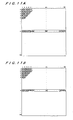
- FIG. 13 is a plan view showing main parts of an inspecting apparatus according to a second embodiment of the present invention
- FIG. 14 is a view taken along line A-A of FIG. 13
- FIG. 15 is a view taken along line B-B of FIG. 13
- the inspection apparatus has a hemispherical member 104 disposed so as to cover a bottle-mouth portion 3 of a glass bottle 2.
- the center O of the hemispherical member 104 is substantially aligned with the bottle-mouth portion 3 of the glass bottle 2.
- a first lighting 107a for applying light to the bottle-mouth portion 3 of the glass bottle 2 is provided on the side of the hemispherical member 104, i.e., at the side of the bottle-mouth portion 3 of the glass bottle 2.
- a plurality of CCD cameras 110-119 are disposed on the hemispherical member 104 so as to surround the bottle-mouth portion 3 of the glass bottle 2.
- the optical axes of the CCD cameras 110-119 are located on lines extending radially from the center O of the hemispherical member 104 (the bottle-mouth portion 3 of the glass bottle 2).
- a total of 10 CCD cameras are provided and one of the cameras 110 constitutes an angle detection camera for detecting a rotation angle of the glass bottle 2 by imaging a screw thread on the bottle-mouth portion 3 of the glass bottle 2.
- the angle detection camera 110 is arranged so that an angle of elevation of its optical axis is equal to 0 degree, and can image the screw thread on the bottle-mouth portion 3 of the glass bottle 2 from a horizontal direction.
- a second lighting 107b is disposed on the side of the hemispherical member 104 facing the angle detection camera 110, and the screw thread on the bottle-mouth portion 3 of the glass bottle 2 is illuminated by the second lighting 107b.
- Light emitted from the second lighting 107b comprises infrared light, and does not interfere with the light emitted from the first lighting 107a.
- the angle detection camera 110 is configured to receive only infrared light emitted from the second lighting 107b.
- the cameras 111-119 other than the angle detection camera 110 constitute inspecting CCD cameras for inspecting a check of the mouth portion 3 by imaging the mouth portion 3 from various angular directions.
- the inspecting CCD cameras 111-119 are arranged so that angles between the optical axes of the respective cameras projected on the horizontal plane and the optical axis of the angle detection camera 110 are 90 degrees (as for a first inspecting CCD camera 111), 130 degrees (as for a second inspecting CCD camera 112), 150 degrees (as for a third inspecting CCD camera 113),180 degrees (as for a fourth inspecting CCD camera 114), 220 degrees (as for a fifth inspecting CCD camera 115, a sixth inspecting CCD camera 116), 260 degrees (as for a seventh inspecting CCD camera 117), 305 degrees (as for an eighth inspecting CCD camera 118), 317 degrees (as for a ninth inspecting CCD camera 119), respectively.
- an angle of elevation of the optical axis of the first inspecting CCD camera 111 is 40 degrees
- an angle of elevation of the optical axis of the second inspecting CCD camera 112 is 35 degrees
- an angle of elevation of the optical axis of the third inspecting CCD camera 113 is 0 degree
- an angle of elevation of the optical axis of the fourth inspecting CCD camera 114 is 50 degrees
- an angle of elevation of the optical axis of the fifth inspecting CCD camera 115 is 40 degrees
- an angle of elevation of the optical axis of the sixth inspecting CCD camera 116 is 10 degrees
- an angle of elevation of the optical axis of the seventh inspecting CCD camera 117 is 35 degrees
- an angle of elevation of the optical axis of the eighth inspecting CCD camera 118 is 35 degrees
- an angle of elevation of the optical axis of the ninth inspecting CCD camera 119 is 0 degree.
- the image processor provided in the inspecting apparatus detects such a brighter area in the image obtained by each of the above CCD cameras 111-119 and judges this brighter area to be a check.
- the light L c from the first lighting 107a is incident into the bottle-mouth portion 3 from the outer circumferential surface of the bottle-mouth portion 3, and passes through the bottle-mouth portion 3 or is reflected from the outer circumferential surface of the bottle-mouth portion 3.
- the light from the molding failure part is scattered in directions where such light is not incident on the corresponding CCD cameras.
- the image becomes dimmer and blurrier than the image of the normally molded screw thread portion, and hence the molding failure can be detected.
- the structure of the image processor is the same as that of the image processor in the inspecting apparatus according to the first embodiment, and the description of the former is omitted.
- Infrared light from the second lighting 107b is applied to the bottle mouth from a side part of the bottle-mouth portion 3 of the glass bottle 2 placed on the turntable 1, and then passes through the bottle-mouth portion 3.
- the infrared light which has passed through the bottle-mouth portion 3 is imaged by the angle detection camera 110 provided so as to face the second lighting 107b.
- the angle detection camera 110 images the thread screw on the bottle-mouth portion 3 to detect the rotation angle of the glass bottle with respect to the reference position at the time of imaging.
- diffused light from the first lighting 107a is applied to the bottle-mouth portion 3 of the glass bottle 2 placed on the turntable 1.
- the inspecting CCD cameras 111-119 image light reflected from the bottle-mouth portion 3 of the glass bottle 2. In this case, if there is a check inside the bottle-mouth portion 3, the light which has been incident into the bottle-mouth from the outer circumferential surface of the bottle-mouth portion 3 is reflected by the crack plane of the check, and the reflected light passes through the bottle-mouth portion 3 and is imaged by the CCD cameras 111-119.
- the relative positions of the respective inspecting CCD cameras 111-119 to the angle detection camera 110 are predetermined. Therefore, by displacing the reference position relatively, the rotation angle detected by the angle detection camera 110 can be used as a rotation angle when the respective inspecting CCD cameras 111-119 image the bottle-mouth portion 3. Therefore, in the present embodiment, the rotation angle which has been detected by the angle detection camera 110 is written on each of the images which have been imaged by the respective inspecting CCD cameras 111-119. As with the first embodiment, the image obtained from the glass bottle to be inspected is compared with the reference image (template) to judge the presence or absence of a check in the bottle-mouth portion.
- the reference image template
- the computing boards 30-40 of the image processor 8 of the inspection apparatus in the first inspection station and the computing boards 130-139 of the image processor 108 of the inspection apparatus in the second inspection station are connected to a host computer 141 through, for example, an ether net 140, thereby producing the above reference image.
- images which have been imaged by the CCD cameras 10-20 and 110-119 in the respective inspection apparatuses may be sent to the host computer 141, and reference images may be produced by the host computer 141 on the basis of these images.
- plural glass bottles as samples are imaged by the CCD camera, and the range of brightness of the non-defective glass bottle is specified from the obtained plural images, thereby producing a reference image.
- the reference image is prepared in advance on the basis of the glass bottle having no defect (non-defective bottle), and an actual image obtained by imaging the glass bottle to be inspected is compared with the reference image, and hence a defect at a specific part of the glass bottle can be detected.
- the kind of a glass bottle to be inspected is changed, it is not necessary to readjust the arrangement relationship between the lighting serving as a light-emitting unit and the CCD camera serving as a light-receiving unit, and the adjustment time for changing the kind of a glass bottle can be remarkably shortened.
- defects at a specific part of a glass bottle such as a check in a screw thread portion of the glass bottle, a check in a seam part of the bottle, and the like can be detected.
- Embodiments of the present invention are suitable for use in a method and apparatus for producing a reference image (template) used in a glass bottle inspecting apparatus for detecting a defect at a specific location of a bottle-mouth portion and the like of a glass bottle, and used for being compared with the image obtained from the glass bottle to be inspected in the inspecting apparatus.
- a reference image template
- a method of producing a reference image comprising: forming plural images by imaging a plurality of glass bottles as samples which contains at least one defective glass bottle by a CCD camera; and producing a reference image from the obtained plural images excluding the image of the at least one defective glass bottle, wherein a range of brightness when light is applied to a non-defective glass bottle is specified in the reference image.
- plural glass bottles as samples are imaged by the CCD camera, and the range of brightness of the non-defective glass bottle is specified from the obtained plural images, thereby producing a reference image.
- the range of brightness specified in the reference image is determined by grasping brightness in each pixel in the images of plural non-defective glass bottles, and determining the maximum brightness and the minimum brightness in each pixel, and the range of brightness is between the maximum brightness and the minimum brightness.
- plural images are formed by imaging a glass bottle as one sample simultaneously by a plurality of CCD cameras from a plurality of imaging angles, and the reference image is produced in each predetermined angle.
- images of defective glass bottles are removed from the plural images imaged by the CCD cameras, and only the images of non-defective glass bottles are obtained.
- frequency distribution of brightness of pixels located at the same position of the plural images is obtained, an average value and standard deviation of brightness of the pixels are calculated, and when there is at least one pixel having brightness higher than the average value by a predetermined multiple of the standard deviation or more, an image having the at least one pixel is judged to be an image of a defective glass bottle and then removed.
- frequency distribution of brightness of pixels located at the same position of the plural images is obtained, an average value and standard deviation of brightness of the pixels are calculated, and when there is at least one pixel having brightness lower than or equal to a value calculated by subtracting a predetermined multiple of the standard deviation from the average value, an image having the at least one pixel is judged to be an image of a defective glass bottle and then removed.
- a defect at a specific part of a glass bottle is detected by comparing the reference image obtained by the method according to any one of claims 1 through 6, with an image which is formed by imaging the glass bottle to be inspected by a CCD camera.
- an apparatus for producing a reference image comprising: at least one CCD camera forming plural images by imaging a plurality of glass bottles as samples which contains at least one defective glass bottle; and an image processor producing a reference image from the obtained plural images excluding the image of the at least one defective glass bottle, wherein a range of brightness when light is applied to a non-defective glass bottle is specified in said reference image.
- the range of brightness specified in the reference image is determined by grasping brightness in each pixel in the images of plural non-defective glass bottles, and determining the maximum brightness and the minimum brightness in each pixel, and the range of brightness is between the maximum brightness and the minimum brightness.
- plural images are formed by imaging a glass bottle as one sample simultaneously by a plurality of CCD cameras from a plurality of imaging angles, and the reference image is produced in each predetermined angle.
- an inspecting apparatus for detecting a defect of a glass bottle by imaging light from the glass bottle while the glass bottle is illuminated, and processing the obtained image
- the inspecting apparatus comprising: a lighting disposed at a predetermined position with respect to the glass bottle; a plurality of CCD cameras disposed around the glass bottle for imaging a specific part of the glass bottle; and an image processor for processing the images obtained by the CCD cameras; wherein the image processor detects a defect at a specific part of the glass bottle by producing and comparing the reference image using the apparatus according to any one of claims 8 through 10, with an image formed by imaging the glass bottle to be inspected by the CCD cameras.
Landscapes
- Engineering & Computer Science (AREA)
- Physics & Mathematics (AREA)
- General Physics & Mathematics (AREA)
- Theoretical Computer Science (AREA)
- General Health & Medical Sciences (AREA)
- Health & Medical Sciences (AREA)
- Life Sciences & Earth Sciences (AREA)
- Computer Vision & Pattern Recognition (AREA)
- Biochemistry (AREA)
- Analytical Chemistry (AREA)
- Chemical & Material Sciences (AREA)
- Immunology (AREA)
- Pathology (AREA)
- Evolutionary Computation (AREA)
- Artificial Intelligence (AREA)
- Data Mining & Analysis (AREA)
- Medical Informatics (AREA)
- Software Systems (AREA)
- Computing Systems (AREA)
- Multimedia (AREA)
- Databases & Information Systems (AREA)
- Quality & Reliability (AREA)
- Bioinformatics & Cheminformatics (AREA)
- Bioinformatics & Computational Biology (AREA)
- Evolutionary Biology (AREA)
- General Engineering & Computer Science (AREA)
- Investigating Materials By The Use Of Optical Means Adapted For Particular Applications (AREA)
Abstract
Description
- The present invention relates to a method and apparatus for producing a reference image (template) in a glass bottle inspecting apparatus, and more particularly to a method and apparatus for producing a reference image (template) used in a glass bottle inspecting apparatus for detecting a defect at a specific location of a bottle-mouth portion and the like of a glass bottle, and used for being compared with the image obtained from the glass bottle to be inspected in the inspecting apparatus.
- An image processing method known as the Golden Template Comparison is disclosed by
US 6 134 343 . - In producing a glass bottle, a crack such as crazing may be sometimes formed in a wall thickness of a bottle-mouth portion. This crack is referred to as a check. The location of the bottle-mouth portion where a check is generated is limited to some extent, and typically there are a mouth-check generated in the top surface or near the top surface of the bottle mouth, a screw-check generated in a screw thread portion of the bottle mouth, and a neck-check generated in a neck portion of the bottle mouth. Further, depending on the direction of the crack, the checks are classified into a vertical check extending in a vertical direction (substantially vertical direction), a lateral check extending in a lateral direction (substantially horizontal direction), and a skew check extending in an oblique direction.
- Because the above-mentioned check can cause damage to the glass bottle, the presence or absence of a check is detected by imaging the bottle-mouth portion, and the glass bottle having the check is removed as a defective bottle.
- Conventionally, there has been known an inspecting apparatus for inspecting a check of a glass bottle which can inspect the presence or absence of a check automatically by imaging a bottle-mouth portion of a glass bottle. The check inspecting apparatus comprises plural pairs of light-emitting units and light-receiving units which are arranged so as to surround the bottle-mouth portion of the glass bottle, and the plural pairs of the light-emitting units and the light-receiving units are adjusted and arranged in an optimum position with respect to the bottle-mouth portion of the glass bottle to be inspected. Then, reflected light from the glass bottle is received by each pair of the light-emitting unit and the light-receiving unit, and the obtained signals are processed to detect a check in the bottle-mouth portion. In this case, light emitted from the light-emitting unit is applied to the bottle-mouth portion, and if there is a check, the light is reflected by a crack plane of the check and is thus luminous brightly. Therefore, the reflected light is received by the light-receiving unit which is the companion to the light-emitting unit, and the check of the bottle portion is detected by judging from the presence or absence of a portion having brightness of a predetermined value or more.
- The above-mentioned conventional check inspection apparatus has plural inspection stations for inspecting a check in the bottle-mouth portion of the glass bottle, and the glass bottle is held and conveyed along a circumference by a star wheel for inspection, and is then indexed in the plural inspection stations. In the plural inspection stations, while the glass bottle is rotated about its own axis, the glass bottle is inspected to detect each defect such as a mouth-check, a screw-check, or a neck-check individually.
- The above-mentioned conventional check inspection apparatus is constructed so that plural inspection stations are provided, and plural pairs of light-emitting units and light-receiving units are arranged in each of the inspection stations. Therefore, when the kind of a glass bottle to be inspected is changed, the arrangement of the plural pairs of the light-emitting units and the light-receiving units must be readjusted in each of the inspection stations. Specifically, angles and heights of the plural pairs of the light-emitting units and the light-receiving units in each of the inspection stations must be readjusted, and the sensitivity and the like of the light-receiving unit must be readjusted.
- Further, in the glass bottle having a screw thread portion on a bottle-mouth portion, the screw thread portion has complicated curved surfaces. Therefore, in many cases, reflected light similar to the reflected light caused by the check is produced in the screw thread portion. However, even if the reflected light is produced from an area where the screw thread portion is located, processing is carried out so as not to judge that there is a check. Therefore, even if there is a check in the screw thread portion and areas above and below the screw thread portion, such a check cannot be detected. Further, the seam portion of the bottle is formed into a curved surface extending continuously in the vertical direction. Therefore, in many cases, reflected light similar to the reflected light caused by the check is produced in this seam portion. Thus, the same processing as in the screw thread portion is carried out in this seam portion. Consequently, even if there is a check in the seam portion and an area around the seam portion, such a check cannot be detected. That is, in a specific part of a glass bottle, even if the glass bottle is normal, an image of the normal glass bottle which has been imaged by a light-receiving unit becomes the same image as a defective glass bottle. Thus, a non-defective bottle and a defective bottle cannot be distinguished from each other. Further, conventionally, it is difficult to detect a molding failure in the screw thread portion or the like which is generated in molding a bottle.
- Therefore, there has been a demand for a glass bottle inspecting apparatus which can detect defects at a specific location of a glass bottle such as a defect in areas located above and below a screw thread portion or a defect located around a seam portion of the bottle, and a molding failure in the bottle (particularly, the screw thread portion) without a need for readjustment of arrangement of light-emitting units and light-receiving units when the kind of a glass bottle to be inspected is changed.
- The invention provides a method according to
claim 1 and an apparatus according toclaim 8. Preferred embodiments are claimed in the dependent claims. - At least one embodiment described hereinafter provides a method and apparatus for producing a reference image (template) used in a glass bottle inspecting apparatus which can detect a defect at a specific location of a glass bottle without a need for readjustment when the kind of a glass bottle is changed.
- To enable a better understanding of the invention, and to show how the same may be carried into effect, reference will now be made, by way of example only, to the accompanying drawings, in which:
-
FIG. 1 is a vertical cross-sectional view of an inspecting apparatus according to a first embodiment of the present invention; -
FIG. 2 is a plan view of a hemispherical member of the inspecting apparatus shown inFIG. 1 ; -
FIG. 3 is a schematic view showing the behavior of light from a lighting according to the first embodiment of the present invention; -
FIG. 4 is a schematic view showing the relationship between an image processor and CCD cameras in the inspecting apparatus according to the first embodiment of the present invention; -
FIG. 5 is a schematic view showing an example of an image on which angle information and the mold number are written; -
FIG. 6 is a schematic view showing an image of a glass bottle as a sample; -
FIG. 7 is a histogram showing brightness distribution of pixels; -
FIG. 8 is a schematic view showing an image of a non-defective glass bottle; -
FIG. 9 is a graph showing brightness distribution of pixels in a certain row; -
FIG. 10 is a view showing the relationship between a template and brightness distribution of each pixel in an image of a glass bottle to be inspected; -
FIG. 11A is a schematic view showing a bright template andFIG. 11B is a schematic view showing a dark template; -
FIG. 12A is a view showing a bright template image imaged on the basis of numerical values of the bright template shown inFIG. 11A , andFIG. 12B is a view showing a dark template image imaged on the basis of numerical values of the dark template shown inFIG. 11B ; -
FIG. 13 is a plan view showing main parts of an inspecting apparatus according to a second embodiment of the present invention; -
FIG. 14 is a view taken along line A-A ofFIG. 13 ; -
FIG. 15 is a view taken along line B-B ofFIG. 13 ; -
FIG. 16 is a schematic view showing the behavior of light from a lighting according to the second embodiment of the present invention; and -
FIG. 17 is a schematic view showing the relationship between an image processor and CCD cameras in the inspecting apparatus according to the second embodiment of the present invention. - A glass bottle inspecting apparatus according to an embodiment of the present invention will be described with reference to
FIGS. 1 through 7 . In the embodiment of the glass bottle inspecting apparatus of the present invention, a case where a specific part of a glass bottle to be inspected corresponds to a bottle-mouth portion and a defect to be inspected is a check in the bottle-mouth portion or a molding failure in a screw thread portion or the like will be described. - A glass bottle to be inspected is held by a star wheel for inspection (not shown), and is conveyed along a conveyance path on a circumference of the star wheel. The glass bottle inspecting apparatus according to this embodiment is disposed in one station (first inspection station) at a certain place in the conveyance path on the circumference of the star wheel. In the first inspection station, the glass bottle conveyed by the star wheel is indexed, and a check in a bottle-mouth portion or a molding failure in a screw thread portion or the like is detected by the glass bottle inspecting apparatus according to this embodiment.
-
FIG. 1 is a vertical cross-sectional view showing a glass bottle inspecting apparatus according to a first embodiment of the present invention. As shown inFIG. 1 , the inspecting apparatus comprises ahemispherical member 4 disposed so as to cover a bottle-mouth portion 3 of aglass bottle 2 placed on arotatable turntable 1, and asupport 5 for supporting thehemispherical member 4. The center O of thehemispherical member 4 is substantially aligned with the bottle-mouth portion 3 of theglass bottle 2 placed on theturntable 1. Thehemispherical member 4 is attached to thesupport 5 through a slidingmember 6 which is vertically movable, and is configured to be movable vertically with respect to thesupport 5. -
FIG. 2 is a plan view of thehemispherical member 4 shown inFIG. 1 . As shown inFIGS. 1 and2 , alighting 7 for applying light to the interior of the bottle mouth of theglass bottle 2 on theturntable 1 is disposed on the top portion of thehemispherical member 4, i.e., above the top surface of the bottle-mouth portion 3 of theglass bottle 2 on theturntable 1. Further, a plurality of CCD cameras 10-20 are disposed on thehemispherical member 4 so as to surround the bottle-mouth portion 3 of theglass bottle 2. The optical axes of the CCD cameras 10-20 are located on lines extending radially from the center O of the hemispherical member 4 (the bottle-mouth portion 3 of the glass bottle 2). - In the present embodiment, a total of 11 CCD cameras are provided and one of the
cameras 10 constitutes an angle detection camera for detecting a rotation angle of theglass bottle 2 with respect to a predetermined reference position by imaging a screw thread on the bottle-mouth portion 3 of theglass bottle 2 placed on theturntable 1. As shown inFIG. 1 , theangle detection camera 10 is arranged so that an angle of elevation of its optical angle is equal to 0 degree, and can image the screw thread on the bottle-mouth portion 3 of theglass bottle 2 from a horizontal direction. - The cameras 11-20 other than the
angle detection camera 10 constitute the inspecting CCD cameras for inspecting a check of the bottle-mouth portion 3 by imaging the bottle-mouth portion 3 from various angular directions. In the present embodiment, the inspecting CCD cameras 11-20 are arranged so that angles between the optical axes of the respective cameras projected on the horizontal plane and the optical axis of theangle detection camera 10 are 25 degrees (as for a first inspectingCCD camera 11 and a second inspecting CCD camera 12), 59.5 degrees (as for a third inspecting CCD camera 13), 140 degrees (as for a fourth inspectingCCD camera 14 and a fifth inspecting camera 15), 185 degrees (as for a sixth inspecting CCD camera 16), 220 degrees (as for a seventh inspecting CCD camera 17), 260 degrees (as for an eighth inspecting CCD camera 18), 296.5 degrees (as for a ninth inspecting CCD camera 19), and 326 degrees (as for a tenth inspecting CCD camera 20), respectively. - Further, an angle of elevation of the optical axis of the first inspecting
CCD camera 11 is 30 degrees, an angle of elevation of the optical axis of the second inspectingCCD camera 12 is 0 degree, an angle of elevation of the optical axis of the fourth inspectingCCD camera 14 is 55 degrees, an angle of elevation of the optical axis of the fifth inspectingCCD camera 15 is 15 degrees, an angle of elevation of the optical axis of the sixth inspectingCCD camera 16 is 45 degrees, an angle of elevation of the optical axis of the seventh inspectingCCD camera 17 is 20 degrees, an angle of elevation of the optical axis of the eighth inspectingCCD camera 18 is 35 degrees, and an angle of elevation of the optical axis of the tenth inspectingCCD camera 20 is 25 degrees. The third inspectingCCD camera 13 and the ninth inspectingCCD camera 19 are configured to be movable up and down on the surface of thehemispherical member 4, and hence the angles of the elevation of the optical axes of the third inspectingCCD camera 13 and the ninth inspectingCCD camera 19 can be freely set. - The number of pixels of each of the CCD cameras 10-20 used in the present embodiment is 64 × 64, and one image can be imaged at intervals of 0.4 milliseconds. For example, in the case of inspecting 300 glass bottles in one minute, the processing time of one glass bottle is 200 milliseconds. In the case where the glass bottle is imaged for 100 milliseconds during the processing time, 250 images (=100/0.4) for each glass bottle can be imaged at a maximum. While the bottle-
mouth portion 3 of theglass bottle 2 is inspected by the inspecting apparatus, theturntable 1 rotates, and theglass bottle 2 is imaged simultaneously by the CCD cameras 10-20 in such a state that theglass bottle 2 is rotated. In this manner, while theglass bottle 2 is rotated, theglass bottle 2 is repeatedly imaged, and hence the bottle-mouth portion 3 of theglass bottle 2 can be imaged over the full circumference of the bottle-mouth portion 3. - Here, light from the
lighting 7 disposed above theglass bottle 2 is applied to the interior of the bottle mouth of theglass bottle 2, and as shown inFIG. 3 , part of light LA is incident into the bottle-mouth portion 3 from the inner circumferential surface of the bottle-mouth portion 3. If there is a check C inside the bottle-mouth portion 3, the light LA is reflected by the crack plane of the check C inside the bottle-mouth portion 3, and the reflected light LB passes through the bottle-mouth portion 3 and is imaged by the inspecting CCD cameras 11-20. The light LB reflected by the crack plane of the check C is brighter than light which has passed through other parts, and hence the part corresponding to the check C becomes a brighter area than other parts in the image which has been imaged by the CCD camera. The image processor provided in the inspecting apparatus detects such a brighter area in the image obtained by each of the above CCD cameras 10-20 and judges the brighter area to be a check. On the other hand, if there is no check C inside the bottle-mouth portion 3, part of the light LA is incident into the bottle-mouth portion 3 from the inner circumferential surface of the bottle-mouth portion 3 and passes through the bottle-mouth portion 3. In this case, if there is a molding failure in the screw thread portion or the like, the light from the molding failure part is scattered in directions where such light is not incident on the corresponding CCD cameras. Thus, the image becomes dimmer and blurrier than the image of the normally molded screw thread portion, and hence the molding failure can be detected. -
FIG. 4 is a schematic view showing the relationship between the image processor and the respective CCD cameras 10-20. As shown inFIG. 4 , theimage processor 8 has computing boards 30-40 corresponding to the CCD cameras 10-20, and these computing boards 30-40 are connected to the corresponding CCD cameras 10-20, respectively. - The relationship between the height position of the spiral of the screw thread on the
glass bottle 2 and the rotation angle of theglass bottle 2 with respect to a predetermined reference position is stored in advance in the angledetection computing board 30 connected to theangle detection camera 10. The angledetection computing board 30 detects the height position of the spiral of the screw thread from the image obtained by theangle detection camera 10, and then detects the rotation angle of theglass bottle 2 at the time of imaging with respect to the reference position from the height position of the spiral of the screw thread on the basis of the above relationship. Signals of the detected rotation angles of theglass bottle 2 are sent to the computing boards 31-40 connected to the respective inspecting CCD cameras 11-20. Thus, theangle detection camera 10 and the angledetection computing board 30 constitute an angle detection device for detecting the rotation angle of the glass bottle with respect to the reference position at the time of imaging. - As described above, the rotation angle of the
glass bottle 2 which has been sent from the angledetection computing board 30 is sent to the computing boards 31-40 connected to the respective inspecting CCD cameras 11-20, and the rotation angle is written as rotation angle information on each of the images which have been imaged by the respective inspecting CCD cameras 11-20. - Next, the operation of the glass bottle inspecting apparatus having the above structure will be described with reference to
FIGS. 1 through 4 . - As described above, diffused light from the
lighting 7 is applied to the interior of the bottle mouth from an upper part of the bottle-mouth portion 3 of theglass bottle 2 placed on theturntable 1. The diffused light which has been applied to the interior of the bottle mouth is radially diffused and passes through the bottle-mouth portion 3. Then, the transmitted light which has radially passed through the bottle-mouth portion 3 are simultaneously imaged by all of the CCD cameras (11 CCD cameras) 10-20 disposed around the bottle-mouth portion 3. At this time, as described above, one CCD camera constitutes an angle detection camera, and thisangle detection camera 10 images the thread screw on the bottle-mouth portion 3 to detect a rotation angle of the glass bottle with respect to the reference position at the time of imaging. When the spiral of the screw thread makes one revolution, the height position is changed by one pitch. Therefore, if the relationship between the height position of the spiral of the screw thread and the rotation angle with respect to the reference position is stored beforehand in thecomputing board 30 of theangle detection camera 10, then theangle detection camera 10 can detect an angle with respect to the reference position at the time of imaging. As the reference position, for example, the starting end which is the start of the screw thread is taken as the reference position (0 degree). - In a case where the
angle detection camera 10 is taken as a reference, the relative positions of the respective inspecting CCD cameras 11-20 to theangle detection camera 10 are predetermined. Therefore, by displacing the reference position relatively, the rotation angle detected by the computingboard 30 of theangle detection camera 10 can be used as a rotation angle when the respective inspecting CCD cameras 11-20 image the bottle-mouth portion 3. Therefore, in the present embodiment, the rotation angle which has been transmitted from the angledetection computing board 30 of theangle detection camera 10 is written on each of the images which have been imaged by the respective inspecting CCD cameras 11-20. - While the
glass bottle 2 is rotated by theturntable 1, the transmitted light which has passed through the bottle-mouth portion 3 is imaged at intervals of predetermined time to obtain a large number of images. Then, the angle information at the time of imaging is written on all of the images. - On the other hand, a glass bottle molding machine has a large number of molds, and a large number of bottles are simultaneously formed by these molds. It is known that the property (wall thickness, delicate shape, and the like) of the molded glass bottle largely depends on the mold. Further, the generation of a check in the bottle-mouth portion of the glass bottle depends on the mold. Therefore, information of the mold number for recognizing which mold forms such a glass bottle is written on the image of the glass bottle obtained by the inspecting apparatus of this embodiment. The mold number can be detected by a mold number reading apparatus which reads convex marks formed on the bottle bottom of the glass bottle. Signals from the mold number reading apparatus are inputted into the computing boards 31-40 of the respective inspecting CCD cameras 11-20, and the mold number is written on each of the images. Further, information related to production such as manufacturing number is written on each of the images.
FIG. 5 is a schematic view showing an example of an image on which rotation angle information and the mold number obtained in the above manner are written. Inspection results, for example, a result about whether the glass bottle is non-defective or detective may be written on each of the images. - Next, each image on which angle information, the mold number, and the like are written is compared with a reference image called a template which is prepared before inspection of the glass bottle, and the presence or absence of a check in the bottle-mouth portion of the glass bottle is inspected. In this process, since the reference image (template) is prepared for each angle and each mold number, the reference image corresponding to the angle information and the mold number which have been written on the image obtained by each of the inspecting CCD cameras is selected, and an image of the glass bottle to be inspected is compared with the selected reference image.
- Next, a method of producing a reference image (template) will be described.
- A method of producing a reference image (hereinafter referred to as template when it is considered proper) comprises three processes which are roughly classified. Specifically, the method comprises an imaging process for imaging a plurality of glass bottles used for producing a template by the CCD cameras, an image selection process for selecting images of non-defective glass bottles from a group of the images imaged by the imaging process by removing images of defective glass bottles, and an image producing process for producing a template on the basis of the images selected by the image selecting process. Next, the respective processes will be described in order.
- Basic data of the imaging process carried out in the present embodiment are as follows:
- ① The number of glass bottles used as samples 100
- ② Molding numbers M1-M8
- ③ Angles A1-A8 (Al: 0-45° , A2: 45-90° ,......, A8: 315-360° )
- ④ The number of images per one glass bottle 100
- One hundred glass bottles serving as samples are transferred to an inspection station by an inspecting star wheel, and are imaged by the first through tenth inspecting CCD cameras 11-20 provided in the inspection station. The obtained images are sent to a computer 42 (see
FIG. 4 ) connected to the computing boards 30-40 of the respective inspecting CCD cameras 11-20, and the following processes are carried out by thecomputer 42 on the basis of these images. - Next, an example of producing a template corresponding to the first inspecting
CCD camera 11, the molding number M1, and the angle A1 will be described below. - As described above, 100 images per one glass bottle are imaged, and a total of 10,000 images per 100 glass bottles are imaged by the first inspecting
CCD camera 11. In the case where there are three glass bottles molded by the mold number M1 among 100 glass bottles, the number of images of the glass bottles formed by the mold number M1 is 3× 100 = 300. Therefore, first, 300 images of the glass bottles molded by the mold number M1 are selected from 10,000 images. Further, the images which have been imaged in the angle A1 are selected from the 300 images. In the present embodiment, 35 images are imaged in the angle A1. Therefore, 35 images are selected to produce a template corresponding to the mold number M1 and the angle A1. - If a defective glass bottle is included in a plurality of glass bottles used as samples in producing a template serving as a reference image, then a template containing light caused by a check is produced. Thus, if the template is produced on the basis of the image containing bright light from the location where bright light should not be created, then the glass bottle having a check at such a location cannot be judged to be a defective glass bottle. For this reason, as a preprocess for producing a template, work for removing images of defective glass bottles from a plurality of images used for the template is carried out.
- In the image selecting process, frequency distribution showing brightness distribution of each of pixels for forming an image is produced on the basis of a plurality of images selected by the imaging process.
FIG. 6 is a schematic view showing an image of a glass bottle as a sample.FIG. 7 is a histogram showing brightness distribution of pixels. InFIG. 6 ,reference numeral 50 represents bright areas. InFIG. 7 , the vertical axis of frequency distribution represents the number of pixels, and the horizontal axis represents brightness (0-255). - As shown in
FIG. 6 , the image of each of the CCD cameras 11-20 is composed of a group of pixels comprising 64 vertical × 64 horizontal. The number of pixels can be suitably adjusted. In this example, one image is decomposed into 64 × 64 pixels. Then, the pixels in the first row, the first column from the decomposed pixel group are plotted on the graph for each image. In this manner, the pixels in the first row, the first column for each of 35 images are plotted on the graph successively, and frequency distribution showing brightness distribution of the pixels in the first row, the first column can be obtained. The frequency distribution is produced from the first row, the first column to the 64th row, the 64th column. - Next, the standard deviation σ representing dispersion of brightness is calculated for every obtained frequency distribution. The standard deviation σ is obtained by a general statistical method. Then, detection criterion is set so that the image is judged to be an image of a non-defective glass bottle when brightness of pixels is distributed within a range of ±2σ, for example. In the case where all of the glass bottles serving as samples are non-defective glass bottles, the brightness of all pixels is distributed in the vicinity of substantially average value X. Therefore, as shown in
FIG. 7 , all of the pixels exist within a range of ±2σ. In this case, any image is not removed, and all of 35 images are used for producing a template. - On the other hand, when a glass bottle has a check, the
part 60 on the image representing the presence of a check becomes extremely bright (seeFIG. 6 ). Then, in the frequency distribution, as shown inFIG. 7 , the number of pixels, which is represented by areference numeral 61, having brightness corresponding to thepart 60 is plotted in the area at the right side of +2σ. Then, it is judged that a check is imaged on the image having such pixels. Further, similarly, in the case where there is extremely dark part, the number of pixels having brightness corresponding to the dark part is plotted in the area at the left side of -2σ. Then, the screw thread portion or the like having a molding failure is judged to be imaged on the image having such pixels. Then, these images are removed from the images used for producing a template. In the present embodiment, the image selecting process is carried out using the statistical method. However, the method is not limited to the statistical method, and any method can be used as long as the image to be removed can be specified. For example, a plurality of images which have been obtained by the imaging process may be displayed on a display both for mold numbers and for angles, and an image of a defective glass bottle may be selected by observing the image on the display by an operator. - In the image producing process, reference images to be a template are produced on the basis of a plurality of images selected in the above image selecting process. The image producing process will be described with reference to
FIGS. 8 through 10 .FIG. 8 is a schematic view showing an image of a non-defective glass bottle.FIG. 9 is a graph showing brightness distribution of pixels in a certain row.FIG. 10 is a view showing the relationship between a template and brightness distribution of each pixel in an image of a glass bottle to be inspected. - In the present embodiment, the template is produced for each pixel row of the image. First, a certain pixel row is specified. For example, in
FIG. 8 , the third row is specified. Next, the specified pixel row is scanned in the column direction (lateral direction ofFIG. 8 , the direction of 1, 2, 3 ...... 64), and the brightness of each pixel is represented on the graph. Specifically, each pixel on the specified pixel row is plotted on the graph where the vertical axis represents brightness of pixels and the horizontal axis represents column numbers of pixels. As shown inFIG. 8 , since the pixels in the third row are located in thedark part 70, a line drawn by plotting the respective pixels in the third row on the graph becomes a straight line located in the vicinity ofbrightness 0. - On the other hand, for example, in the case where the pixels in the tenth row are specified, a line drawn by plotting the respective pixels in the tenth row becomes T1 shown in
FIG. 9 . Specifically, in the tenth row, since thebright part 50 formed by light from the screw thread portion is scanned, the pixels corresponding to thebright part 50 show a high brightness. - Further, with regard to all the images, all the pixels in the same row are plotted on one graph. Specifically, in the present embodiment, since 35 images are used for producing a template, as shown in
FIG. 9 , a brightness distribution chart composed of a group of 35 lines (inFIG. 9 , only four lines T1-T4 are shown) is produced. In this manner, brightness distribution charts are produced for all of the rows from the first row to the 64th row. - Then, the maximum area demarcated by a group of these lines becomes an area which should be taken as a template. Specifically, as shown in
FIG. 10 , the line obtained by connecting points representing the maximum value (maximum brightness) in each column is taken as a bright template line Tmax, and the line obtained by connecting points representing the minimum value (minimum brightness) in each column is taken as a dark template line Tmin. An area enclosed by the bright template line Tmax and the dark template line Tmin becomes a reference image (template) to be determined. That is, a range between the maximum brightness and the minimum brightness is continuously formed in the column direction between the bright template line Tmax and the dark template line Tmin. In this manner, 64 templates are produced in the mold number M1 and the angle A1. - Because work for producing these templates is conducted on the mold numbers M1-M20 and the angles A1-A8, 64×20×8=10,240 templates are given to the first inspecting
CCD camera 11. Specifically, each of the inspecting CCD cameras 11-20 has templates for each mold, each angle, and each pixel. As described above, since the property of the glass bottle and the generation of a check largely depend on a mold, the accuracy in detection of a check or a molding failure in the screw thread portion or the like can be enhanced by producing templates corresponding to each of the molds. - Next, there will be described a method of judging the presence or absence of a check in a bottle-mouth portion or a molding failure in a screw thread portion or the like by comparing the reference image (template) obtained by the above method and the image obtained from the glass bottle to be inspected.
- First, the templates produced under the same condition (mold, angle, and the like) as the images to be inspected are selected as comparing object on the basis of various information such as angle information, the mold number, and the like given to the image. Next, the image of the glass bottle to be inspected is compared with the templates in each pixel row. Specifically, the line representing brightness distribution in the column direction in a specific pixel row is compared with a template. Then, as shown in
FIG. 10 , if the line S1 representing brightness of the glass bottle to be inspected is located completely in a non-defective article area of the template (area enclosed by the bright template line Tmax and the dark template line Tmin), then this glass bottle is judged to be a non-defective article. - On the other hand, as shown by a sign S2, if part of the line projects from the non-defective article area of the template, this glass bottle is judged to be a defective article. Then, when all of the pixel rows are compared with the templates, and at least one row is judged to be defective, it is judged that this glass bottle has a check in the bottle-mouth portion or a molding failure in the screw thread portion or the like.
- Such inspection is carried out in each of the angles A1-A8. Therefore, even if it is judged that there is neither a check nor a molding failure in the angle A1, for example, in some cases, it is judged that there is a check or a molding failure in the angle A2. In the present embodiment, because the detection of a check or a molding failure is carried out in a plurality of angles (A1-A8), the accuracy in inspection of a check or a molding failure can be enhanced, compared with the conventional inspection apparatus.
- The 64 templates produced in the above manner may be integrated into a two-dimensional (planar) bright template and a two-dimensional (planar) dark template.
FIG. 11A is a schematic view showing a bright template andFIG. 11B is a schematic view showing a dark template. Next, a process of producing the bright template will be described with reference toFIGS. 10 and11A . - As shown in
FIG. 10 , brightness of the bright template line Tmax in a certain row can be digitized in the range of 0 to 255 in each column. The respective numerical values representing the brightness are plotted in a corresponding row in a table composed of 64 rows × 64 columns shown inFIG. 11A . For example, numerical value representing the brightness held by the m column of the bright template line Tmax in the n row is plotted in a section located in the n row, the m column of the table. InFIG. 11A , the brightness ranging from 0 to 255 is represented by hexadecimal notation. - When all of the brightness of the bright template line Tmax from the first to the 64th row have been plotted in the table, one bright template as shown in
FIG. 11A is produced finally. The dark template shown inFIG. 11B is also produced on the basis of the dark template line Tmin in the same process as the bright template. The range between the maximum brightness and the minimum brightness in each pixel constituting the reference image is determined by the thus obtained bright template and dark template. Specifically, in an example shown inFIGS. 11A and 11B , the range between the minimum brightness and the maximum brightness in the pixel located in the n row, the m column is from 02 to 08.FIG. 12A is a view showing a bright template image imaged on the basis of numerical values of the bright template shown inFIG. 11A , andFIG. 12B is a view showing a dark template image imaged on the basis of numerical values of the dark template shown inFIG. 11B . - In the above description, an example in which the brightness of all pixels in each row is digitized in producing a two-dimensional (planar) bright template and a two-dimensional (planar) dark template is described. However, a two-dimensional bright template and a two-dimensional dark template may be produced by digitizing the brightness of each pixel not in each row but in each pixel.
- The next description is made for a method of judging the presence or absence of a check in the bottle-mouth portion and a molding failure in the screw thread portion or the like in the glass bottle to be inspected by using the bright template and the dark template obtained by the above process. First, the specific row of the image of the glass bottle to be inspected is scanned in the column direction (lateral direction), and the brightness of all pixels in the row is digitized. Next, it is judged whether the brightness of each pixel from the first column to the 64th column in the row exists in a range (hereinafter referred to as non-defective article range) between the maximum brightness and the minimum brightness determined by the bright template and the dark template. This process is conducted on all the rows from the first row to the 64th row.
- Then, if the brightness of all the pixels constituting the image to be inspected exists within the non-defective article range, it is judged that there is neither a check in the bottle-mouth portion nor a molding failure in the screw thread portion or the like in the glass bottle. On the other hand, if the number of pixels which are deviated from the non-defective article range by an allowable value or more is not less than a predetermined number, the image is judged to be an image of a defective glass bottle, and it is judged that there is a check in the bottle-mouth portion or a molding failure in the screw thread portion or the like in this glass bottle. The allowable value related to the non-defective article range and the predetermined number of pixels serving as a criterion for judgment of the defective article can be set according to inspection accuracy to be achieved. For example, if a predetermined number of pixels adjacent to each other in a certain image has brightness outside the non-defective article range, then such an image may be judged to be an image of a defective glass bottle.
- In the embodiment shown in
FIGS. 1 through 12A and 12B, the interior of the bottle mouth of the glass bottle is illuminated, and a check or a molding failure is detected from the transmitted light which has passed through the bottle-mouth portion. With this arrangement, a lateral check extending in a lateral direction and a skew check extending in an oblique direction can be perfectly detected. Further, most of the vertical checks extending in the vertical direction can be also detected. However, if the crack plane of the vertical check is completely aligned with the direction extending radially from the axis of the bottle, the transmitted light which passes through the bottle-mouth portion travels in a direction parallel to the crack plane. Thus, there is a chance that the vertical check cannot be detected. Therefore, according to the second embodiment, a second inspection station is disposed at a certain place in the conveyance path on the circumference of the star wheel, and a glass bottle inspecting apparatus for detecting a vertical check with reflected light is provided in the second inspection station. It is a matter of course that the inspecting apparatus which uses the transmitted light shown inFIGS. 1 through 12A and12B is provided in the first inspection station. - Next, a glass bottle inspecting apparatus for detecting a vertical check will be described with reference to
FIGS. 13 through 16 . -
FIG. 13 is a plan view showing main parts of an inspecting apparatus according to a second embodiment of the present invention,FIG. 14 is a view taken along line A-A ofFIG. 13 , andFIG. 15 is a view taken along line B-B ofFIG. 13 . As shown inFIGS. 13 through 15 , the inspection apparatus has ahemispherical member 104 disposed so as to cover a bottle-mouth portion 3 of aglass bottle 2. The center O of thehemispherical member 104 is substantially aligned with the bottle-mouth portion 3 of theglass bottle 2. Afirst lighting 107a for applying light to the bottle-mouth portion 3 of theglass bottle 2 is provided on the side of thehemispherical member 104, i.e., at the side of the bottle-mouth portion 3 of theglass bottle 2. Further, a plurality of CCD cameras 110-119 are disposed on thehemispherical member 104 so as to surround the bottle-mouth portion 3 of theglass bottle 2. The optical axes of the CCD cameras 110-119 are located on lines extending radially from the center O of the hemispherical member 104 (the bottle-mouth portion 3 of the glass bottle 2). - In the present embodiment, a total of 10 CCD cameras are provided and one of the
cameras 110 constitutes an angle detection camera for detecting a rotation angle of theglass bottle 2 by imaging a screw thread on the bottle-mouth portion 3 of theglass bottle 2. As shown inFIG. 15 , theangle detection camera 110 is arranged so that an angle of elevation of its optical axis is equal to 0 degree, and can image the screw thread on the bottle-mouth portion 3 of theglass bottle 2 from a horizontal direction. Asecond lighting 107b is disposed on the side of thehemispherical member 104 facing theangle detection camera 110, and the screw thread on the bottle-mouth portion 3 of theglass bottle 2 is illuminated by thesecond lighting 107b. Light emitted from thesecond lighting 107b comprises infrared light, and does not interfere with the light emitted from thefirst lighting 107a. Theangle detection camera 110 is configured to receive only infrared light emitted from thesecond lighting 107b. - The cameras 111-119 other than the
angle detection camera 110 constitute inspecting CCD cameras for inspecting a check of themouth portion 3 by imaging themouth portion 3 from various angular directions. In the present embodiment, the inspecting CCD cameras 111-119 are arranged so that angles between the optical axes of the respective cameras projected on the horizontal plane and the optical axis of theangle detection camera 110 are 90 degrees (as for a first inspecting CCD camera 111), 130 degrees (as for a second inspecting CCD camera 112), 150 degrees (as for a third inspecting CCD camera 113),180 degrees (as for a fourth inspecting CCD camera 114), 220 degrees (as for a fifth inspectingCCD camera 115, a sixth inspecting CCD camera 116), 260 degrees (as for a seventh inspecting CCD camera 117), 305 degrees (as for an eighth inspecting CCD camera 118), 317 degrees (as for a ninth inspecting CCD camera 119), respectively. - Further, an angle of elevation of the optical axis of the first inspecting
CCD camera 111 is 40 degrees, an angle of elevation of the optical axis of the second inspectingCCD camera 112 is 35 degrees, an angle of elevation of the optical axis of the third inspectingCCD camera 113 is 0 degree, an angle of elevation of the optical axis of the fourth inspectingCCD camera 114 is 50 degrees, an angle of elevation of the optical axis of the fifth inspectingCCD camera 115 is 40 degrees, an angle of elevation of the optical axis of the sixth inspectingCCD camera 116 is 10 degrees, an angle of elevation of the optical axis of the seventh inspectingCCD camera 117 is 35 degrees, an angle of elevation of the optical axis of the eighth inspectingCCD camera 118 is 35 degrees, and an angle of elevation of the optical axis of the ninth inspectingCCD camera 119 is 0 degree. - As shown in
FIG. 16 , light Lc from thefirst lighting 107a is incident into the bottle-mouth portion 3 from the outer circumferential surface of the bottle-mouth portion 3 of theglass bottle 2. If there is a check (vertical check) C inside the bottle-mouth portion 3, the light Lc is reflected by the crack plane of the check C inside the bottle-mouth portion 3, and the reflected light LD passes through the bottle-mouth portion 3 and is imaged by the inspecting CCD cameras 111-119. The light Lc reflected by the crack plane of the check C is brighter than light which has passed through other parts, and hence the part corresponding to the check C becomes a brighter area than other parts in the image which has been imaged by each of the CCD cameras. The image processor provided in the inspecting apparatus detects such a brighter area in the image obtained by each of the above CCD cameras 111-119 and judges this brighter area to be a check. On the other hand, if there is no check C inside the bottle-mouth portion 3, the light Lc from thefirst lighting 107a is incident into the bottle-mouth portion 3 from the outer circumferential surface of the bottle-mouth portion 3, and passes through the bottle-mouth portion 3 or is reflected from the outer circumferential surface of the bottle-mouth portion 3. In this case, if there is a molding failure in the screw thread portion or the like, the light from the molding failure part is scattered in directions where such light is not incident on the corresponding CCD cameras. Thus, the image becomes dimmer and blurrier than the image of the normally molded screw thread portion, and hence the molding failure can be detected. The structure of the image processor is the same as that of the image processor in the inspecting apparatus according to the first embodiment, and the description of the former is omitted. - Next, the operation of the glass bottle inspecting apparatus having the above structure will be described with reference to
FIGS. 13 through 16 . - Infrared light from the
second lighting 107b is applied to the bottle mouth from a side part of the bottle-mouth portion 3 of theglass bottle 2 placed on theturntable 1, and then passes through the bottle-mouth portion 3. The infrared light which has passed through the bottle-mouth portion 3 is imaged by theangle detection camera 110 provided so as to face thesecond lighting 107b. In the same manner as the first embodiment, theangle detection camera 110 images the thread screw on the bottle-mouth portion 3 to detect the rotation angle of the glass bottle with respect to the reference position at the time of imaging. - On the other hand, diffused light from the
first lighting 107a is applied to the bottle-mouth portion 3 of theglass bottle 2 placed on theturntable 1. The inspecting CCD cameras 111-119 image light reflected from the bottle-mouth portion 3 of theglass bottle 2. In this case, if there is a check inside the bottle-mouth portion 3, the light which has been incident into the bottle-mouth from the outer circumferential surface of the bottle-mouth portion 3 is reflected by the crack plane of the check, and the reflected light passes through the bottle-mouth portion 3 and is imaged by the CCD cameras 111-119. - In a case where the
angle detection camera 110 is taken as a reference, the relative positions of the respective inspecting CCD cameras 111-119 to theangle detection camera 110 are predetermined. Therefore, by displacing the reference position relatively, the rotation angle detected by theangle detection camera 110 can be used as a rotation angle when the respective inspecting CCD cameras 111-119 image the bottle-mouth portion 3. Therefore, in the present embodiment, the rotation angle which has been detected by theangle detection camera 110 is written on each of the images which have been imaged by the respective inspecting CCD cameras 111-119. As with the first embodiment, the image obtained from the glass bottle to be inspected is compared with the reference image (template) to judge the presence or absence of a check in the bottle-mouth portion. - As shown in
FIG. 17 , the computing boards 30-40 of theimage processor 8 of the inspection apparatus in the first inspection station and the computing boards 130-139 of theimage processor 108 of the inspection apparatus in the second inspection station are connected to ahost computer 141 through, for example, an ether net 140, thereby producing the above reference image. Specifically, images which have been imaged by the CCD cameras 10-20 and 110-119 in the respective inspection apparatuses may be sent to thehost computer 141, and reference images may be produced by thehost computer 141 on the basis of these images. - Although embodiments of the present invention have been described above, the present invention is not limited to the above embodiment, but various changes and modifications may be made therein within the scope of the claims.
- As described above, according to the embodiments, plural glass bottles as samples are imaged by the CCD camera, and the range of brightness of the non-defective glass bottle is specified from the obtained plural images, thereby producing a reference image.
- Further, according to at least one embodiment, the reference image is prepared in advance on the basis of the glass bottle having no defect (non-defective bottle), and an actual image obtained by imaging the glass bottle to be inspected is compared with the reference image, and hence a defect at a specific part of the glass bottle can be detected. Thus, when the kind of a glass bottle to be inspected is changed, it is not necessary to readjust the arrangement relationship between the lighting serving as a light-emitting unit and the CCD camera serving as a light-receiving unit, and the adjustment time for changing the kind of a glass bottle can be remarkably shortened. Further, defects at a specific part of a glass bottle such as a check in a screw thread portion of the glass bottle, a check in a seam part of the bottle, and the like can be detected.
- Embodiments of the present invention are suitable for use in a method and apparatus for producing a reference image (template) used in a glass bottle inspecting apparatus for detecting a defect at a specific location of a bottle-mouth portion and the like of a glass bottle, and used for being compared with the image obtained from the glass bottle to be inspected in the inspecting apparatus.
- According to one embodiment described above, there is provided a method of producing a reference image, comprising: forming plural images by imaging a plurality of glass bottles as samples which contains at least one defective glass bottle by a CCD camera; and producing a reference image from the obtained plural images excluding the image of the at least one defective glass bottle, wherein a range of brightness when light is applied to a non-defective glass bottle is specified in the reference image.
- According to at least one embodiment of the present invention, plural glass bottles as samples are imaged by the CCD camera, and the range of brightness of the non-defective glass bottle is specified from the obtained plural images, thereby producing a reference image.
- According to an embodiment described above, the range of brightness specified in the reference image is determined by grasping brightness in each pixel in the images of plural non-defective glass bottles, and determining the maximum brightness and the minimum brightness in each pixel, and the range of brightness is between the maximum brightness and the minimum brightness.
- According to an embodiment described above, plural images are formed by imaging a glass bottle as one sample simultaneously by a plurality of CCD cameras from a plurality of imaging angles, and the reference image is produced in each predetermined angle.
- According to an embodiment described above, before producing the reference image, images of defective glass bottles are removed from the plural images imaged by the CCD cameras, and only the images of non-defective glass bottles are obtained.
- According to an embodiment described above, frequency distribution of brightness of pixels located at the same position of the plural images is obtained, an average value and standard deviation of brightness of the pixels are calculated, and when there is at least one pixel having brightness higher than the average value by a predetermined multiple of the standard deviation or more, an image having the at least one pixel is judged to be an image of a defective glass bottle and then removed.
- According to an embodiment described above, frequency distribution of brightness of pixels located at the same position of the plural images is obtained, an average value and standard deviation of brightness of the pixels are calculated, and when there is at least one pixel having brightness lower than or equal to a value calculated by subtracting a predetermined multiple of the standard deviation from the average value, an image having the at least one pixel is judged to be an image of a defective glass bottle and then removed.
- According to an embodiment described above, a defect at a specific part of a glass bottle is detected by comparing the reference image obtained by the method according to any one of
claims 1 through 6, with an image which is formed by imaging the glass bottle to be inspected by a CCD camera. - According to an embodiment described above, there is provided an apparatus for producing a reference image, comprising: at least one CCD camera forming plural images by imaging a plurality of glass bottles as samples which contains at least one defective glass bottle; and an image processor producing a reference image from the obtained plural images excluding the image of the at least one defective glass bottle, wherein a range of brightness when light is applied to a non-defective glass bottle is specified in said reference image.
- According to an embodiment described above, the range of brightness specified in the reference image is determined by grasping brightness in each pixel in the images of plural non-defective glass bottles, and determining the maximum brightness and the minimum brightness in each pixel, and the range of brightness is between the maximum brightness and the minimum brightness.
- According to an embodiment described above, plural images are formed by imaging a glass bottle as one sample simultaneously by a plurality of CCD cameras from a plurality of imaging angles, and the reference image is produced in each predetermined angle.
- According to an embodiment described above, there is provided an inspecting apparatus for detecting a defect of a glass bottle by imaging light from the glass bottle while the glass bottle is illuminated, and processing the obtained image, the inspecting apparatus comprising: a lighting disposed at a predetermined position with respect to the glass bottle; a plurality of CCD cameras disposed around the glass bottle for imaging a specific part of the glass bottle; and an image processor for processing the images obtained by the CCD cameras; wherein the image processor detects a defect at a specific part of the glass bottle by producing and comparing the reference image using the apparatus according to any one of
claims 8 through 10, with an image formed by imaging the glass bottle to be inspected by the CCD cameras.
Claims (11)
- A method of producing a reference image, comprising:forming plural images by imaging a plurality of glass bottles (2) as samples which contains at least one defective glass bottle by a CCD camera (10-20, 110-119); andproducing a reference image from the obtained plural images excluding the image of the at least one defective glass bottle, wherein a range of brightness when light is applied to a non-defective glass bottle is specified in said reference image.
- A method of producing a reference image according to claim 1, wherein said range of brightness specified in said reference image is determined by grasping brightness in each pixel in the images of plural non-defective glass bottles, and determining the maximum brightness and the minimum brightness in each pixel, and said range of brightness is between the maximum brightness and the minimum brightness.
- A method of producing a reference image according to claim 1 or 2, wherein plural images are formed by imaging a glass bottle (2) as one sample simultaneously by a plurality of CCD cameras (10-20, 110-119) from a plurality of imaging angles, and said reference image is produced in each predetermined angle.
- A method of producing a reference image according to any one of claims 1 through 3, wherein before producing said reference image, images of defective glass bottles are removed from said plural images imaged by said CCD cameras (10-20, 110-119), and only the images of non-defective glass bottles are obtained.
- A method of producing a reference image according to claim 4, wherein frequency distribution of brightness of pixels located at the same position of said plural images is obtained, an average value and standard deviation of brightness of said pixels are calculated, and when there is at least one pixel having brightness higher than said average value by a predetermined multiple of said standard deviation or more, an image having said at least one pixel is judged to be an image of a defective glass bottle and then removed.
- A method of producing a reference image according to claim 4, wherein frequency distribution of brightness of pixels located at the same position of said plural images is obtained, an average value and standard deviation of brightness of said pixels are calculated, and when there is at least one pixel having brightness lower than or equal to a value calculated by subtracting a predetermined multiple of said standard deviation from said average value, an image having said at least one pixel is judged to be an image of a defective glass bottle and then removed.
- A method of inspecting a glass bottle, wherein a defect at a specific part of a glass bottle (2) is detected by comparing the reference image obtained by the method according to any one of claims 1 through 6, with an image which is formed by imaging the glass bottle (2) to be inspected by a CCD camera (10-20, 110-119).
- An apparatus for producing a reference image, comprising:at least one CCD camera (10-20, 110-119) forming plural images by imaging a plurality of glass bottles (2) as samples which contains at least one defective glass bottle; andan image processor (8) adapted to produce a reference image from the obtained plural images by excluding the image of the at least one defective glass bottle, wherein a range of brightness when light is applied to a non-defective glass bottle is specified in said reference image.
- An apparatus for producing a reference image according to claim 8, wherein said range of brightness specified in said reference image is determined by grasping brightness in each pixel in the images of plural non-defective glass bottles, and determining the maximum brightness and the minimum brightness in each pixel, and said range of brightness is between the maximum brightness and the minimum brightness.
- An apparatus for producing a reference image according to claim 8 or 9, wherein plural images are formed by imaging a glass bottle (2) as one sample simultaneously by a plurality of CCD cameras (10-20, 110-119) from a plurality of imaging angles, and said reference image is produced in each predetermined angle.
- An inspecting apparatus for detecting a defect of a glass bottle (2) by imaging light from the glass bottle while the glass bottle is illuminated, and processing the obtained image, the inspecting apparatus comprising:a lighting (7) disposed at a predetermined position with respect to the glass bottle;a plurality of CCD cameras (10-20, 110-119) disposed around the glass bottle (2) for imaging a specific part of the glass bottle (2); andan image processor (8) for processing the images obtained by said CCD cameras;wherein said image processor (8) detects a defect at a specific part of the glass bottle (2) by producing and comparing the reference image using said apparatus according to any one of claims 8 through 10, with an image formed by imaging the glass bottle (2) to be inspected by said CCD cameras (10-20, 110-119).
Applications Claiming Priority (1)
| Application Number | Priority Date | Filing Date | Title |
|---|---|---|---|
| PCT/JP2002/010839 WO2004036198A1 (en) | 2002-10-18 | 2002-10-18 | Method and device for preparing reference image in glass bottle inspection device |
Publications (3)
| Publication Number | Publication Date |
|---|---|
| EP1560018A1 EP1560018A1 (en) | 2005-08-03 |
| EP1560018A4 EP1560018A4 (en) | 2006-09-06 |
| EP1560018B1 true EP1560018B1 (en) | 2008-02-27 |
Family
ID=32104839
Family Applications (1)
| Application Number | Title | Priority Date | Filing Date |
|---|---|---|---|
| EP02777887A Expired - Lifetime EP1560018B1 (en) | 2002-10-18 | 2002-10-18 | Method and device for preparing reference image in glass bottle inspection device |
Country Status (6)
| Country | Link |
|---|---|
| US (1) | US7330251B2 (en) |
| EP (1) | EP1560018B1 (en) |
| JP (1) | JP4478786B2 (en) |
| AU (1) | AU2002344112A1 (en) |
| DE (1) | DE60225354T2 (en) |
| WO (1) | WO2004036198A1 (en) |
Families Citing this family (35)
| Publication number | Priority date | Publication date | Assignee | Title |
|---|---|---|---|---|
| US7454050B2 (en) | 2004-06-18 | 2008-11-18 | Csi Technology, Inc. | Method of automating a thermographic inspection process |
| FR2907553B1 (en) * | 2006-10-24 | 2009-02-13 | Tiama Sa | METHOD AND DEVICE FOR DETECTING LOW AND HIGH CONTRAST DEFECTS IN TRANSPARENT OR TRANSLUCENT OBJECTS |
| US7688437B2 (en) | 2007-05-02 | 2010-03-30 | Emhart Glass S.A. | Machine for inspecting glass containers |
| US7697132B2 (en) * | 2007-05-02 | 2010-04-13 | Emhart Glass S.A. | Machine for inspecting glass containers |
| FR2916048B1 (en) | 2007-05-09 | 2010-05-28 | Tiama | METHOD AND DEVICE FOR INSPECTING TRANSPARENT OR TRANSLUCENT ARTICLES IN ORDER TO OPTIMIZE THE OPERATION OF A CONTROL MACHINE |
| US20100007715A1 (en) * | 2008-07-09 | 2010-01-14 | Ortery Technologies, Inc. | Method of Shooting Angle Adjustment for an Image Capturing Device that Moves Along a Circular Path |
| DE102010032410B4 (en) * | 2010-07-27 | 2014-11-13 | Mall + Herlan Schweiz Ag | Inspection device, manufacturing plant with inspection device and inspection method for vessels |
| KR101707270B1 (en) * | 2010-10-01 | 2017-02-15 | 기린 테크노시스템 가부시끼가이샤 | Glass bottle inspection apparatus and method |
| DE102010047618A1 (en) * | 2010-10-07 | 2012-04-12 | Krones Aktiengesellschaft | Optical threaded position detection device |
| DE102011004584A1 (en) * | 2011-02-23 | 2012-08-23 | Krones Aktiengesellschaft | Method and apparatus for detecting bubbles and / or wrinkles on labeled containers |
| US8896828B2 (en) | 2011-03-29 | 2014-11-25 | Owens-Brockway Glass Container Inc. | Optical inspection of containers |
| DE102011106136A1 (en) * | 2011-06-10 | 2012-12-13 | Khs Gmbh | Empty bottle inspection |
| KR101775195B1 (en) * | 2011-06-15 | 2017-09-05 | 기린 테크노시스템 가부시끼가이샤 | Glass bottle inspection method and apparatus |
| DE102011108754A1 (en) * | 2011-07-28 | 2013-01-31 | Khs Gmbh | inspection unit |
| JP5597220B2 (en) * | 2012-03-30 | 2014-10-01 | 日本山村硝子株式会社 | Glass glare inspection device and method of inspection using the same |
| FR2991052B1 (en) * | 2012-05-28 | 2015-05-01 | Msc & Sgcc | OPTICAL METHOD FOR INSPECTING TRANSPARENT OR TRANSLUCENT CONTAINERS WITH VISUAL REASONS |
| US8941825B2 (en) | 2013-03-15 | 2015-01-27 | Owens-Brockway Glass Container Inc. | Container inspection |
| DE102014002582B4 (en) * | 2014-02-26 | 2018-10-11 | Heye International Gmbh | Method for detecting cracks in the walls of hollow glass articles |
| CN203831672U (en) * | 2014-04-16 | 2014-09-17 | 法国圣戈班玻璃公司 | Injection molding device |
| US10257473B2 (en) * | 2015-01-27 | 2019-04-09 | Sercomm Corporation | Doorbell device and method thereof |
| JP6338069B2 (en) * | 2016-10-31 | 2018-06-06 | ソリッドビジョン株式会社 | Image processing system and image processing method |
| CN110431405B (en) * | 2017-02-06 | 2022-06-14 | 东洋玻璃株式会社 | Inspection device for glass bottles |
| JP6671309B2 (en) * | 2017-03-13 | 2020-03-25 | 株式会社Screenホールディングス | Inspection device and inspection method |
| IT201900005540A1 (en) * | 2019-04-10 | 2020-10-10 | Doss Visual Solution S R L | OPTICAL INSPECTION MACHINE FOR PARTS QUALITY CONTROL |
| EP3797883B1 (en) | 2019-09-27 | 2022-06-08 | SCHOTT Schweiz AG | Apparatus for inspecting a pharmaceutical container |
| EP3798621B1 (en) | 2019-09-27 | 2022-11-23 | SCHOTT Schweiz AG | Apparatus for inspecting a pharmaceutical container |
| JP7491315B2 (en) * | 2019-10-02 | 2024-05-28 | コニカミノルタ株式会社 | Work surface defect detection device and detection method, work surface inspection system and program |
| CN110618140A (en) * | 2019-11-01 | 2019-12-27 | 杭州深度视觉科技有限公司 | Machine vision detection system and method for bearing ring grinding vibration lines |
| DE102019132654A1 (en) * | 2019-12-02 | 2021-06-02 | Krones Aktiengesellschaft | Inspection procedures for inspecting containers |
| CN110927178A (en) * | 2019-12-11 | 2020-03-27 | 浙江一诺机电有限公司 | An automatic detection device for product appearance and defects |
| EP3855175B1 (en) * | 2020-01-23 | 2023-03-29 | SCHOTT Pharma Schweiz AG | Detection and characterization of defects in pharmaceutical cylindrical containers |
| DE102020121088A1 (en) * | 2020-08-11 | 2022-02-17 | Krones Aktiengesellschaft | Device and method for inspecting closed containers |
| CN114236885B (en) * | 2021-11-10 | 2023-09-12 | 云南电网有限责任公司 | Electric energy meter liquid crystal display machine vision detection system and method |
| CN116977310B (en) * | 2023-08-01 | 2024-01-26 | 山东明佳科技有限公司 | Image detection method, system, equipment and storage medium for bottle mouth gap of milk glass bottle |
| KR102855437B1 (en) * | 2024-05-20 | 2025-09-04 | 주식회사 아이브 | Apparatus for Separation Rotating Imaging |
Family Cites Families (23)
| Publication number | Priority date | Publication date | Assignee | Title |
|---|---|---|---|---|
| JPS6269154A (en) * | 1985-09-21 | 1987-03-30 | Hajime Sangyo Kk | Defect inspection instrument for mouth of bottle |
| JPS63277960A (en) | 1987-05-11 | 1988-11-15 | Shokuhin Sangyo Onrain Sensor Gijutsu Kenkyu Kumiai | Inspecting method for defect in threaded neck part |
| US5126556A (en) * | 1989-12-04 | 1992-06-30 | Coors Brewing Company | Bottle thread imaging apparatus having a light seal means between the light assembly means and the thread |
| JP2759231B2 (en) | 1991-03-22 | 1998-05-28 | 山村硝子株式会社 | Defect inspection system for glass bottles |
| JPH0783851A (en) * | 1993-06-29 | 1995-03-31 | Lion Eng Kk | Method for detecting and processing defective |
| US5444535A (en) * | 1993-08-09 | 1995-08-22 | Labatt Brewing Company Limited | High signal-to-noise optical apparatus and method for glass bottle thread damage detection |
| ATE182706T1 (en) * | 1994-12-05 | 1999-08-15 | Du Pont | ADAPTIVE VISION SYSTEM WITH DUAL THRESHOLD PROCESSING |
| JPH08247960A (en) * | 1995-03-14 | 1996-09-27 | Adtec Eng:Kk | Visual inspection device |
| JPH08300632A (en) * | 1995-05-10 | 1996-11-19 | Toshiba Mach Co Ltd | Printed matter monitoring device |
| DE69610925T2 (en) * | 1995-08-04 | 2001-06-13 | Image Processing Systems, Inc. | DEVICE FOR EXAMINING BOTTLE THREADS AND METHOD FOR THE OPERATION THEREOF |
| JPH09119902A (en) | 1995-09-13 | 1997-05-06 | Nippon Glass Kk | Inspection device for bottle mouth and screw |
| JP2891947B2 (en) | 1996-09-05 | 1999-05-17 | 株式会社プレシジョン | Inspection device for bottle mouth and screw |
| US5987159A (en) * | 1996-09-24 | 1999-11-16 | Cognex Corporation | System or method for detecting defect within a semi-opaque enclosure |
| JP3357802B2 (en) | 1996-10-16 | 2002-12-16 | 三洋電機株式会社 | Inspection method of printed matter and its inspection device |
| JPH10123064A (en) * | 1996-10-24 | 1998-05-15 | Hitachi Metals Ltd | Visual inspection |
| JPH10160430A (en) | 1996-11-29 | 1998-06-19 | Precision:Kk | Apparatus for visual inspection of containers on conveyor line |
| US6295374B1 (en) * | 1998-04-06 | 2001-09-25 | Integral Vision, Inc. | Method and system for detecting a flaw in a sample image |
| JP2000171230A (en) * | 1998-09-29 | 2000-06-23 | Toshiba Corp | Fine pattern shape inspection method and apparatus |
| JP2000180382A (en) * | 1998-12-11 | 2000-06-30 | Mitsubishi Nuclear Fuel Co Ltd | Visual examination apparatus |
| JP2000214104A (en) | 1999-01-26 | 2000-08-04 | Precision:Kk | Glass bottle defect inspection system |
| JP2002195958A (en) * | 2000-12-26 | 2002-07-10 | Yamatake Corp | Surface inspection method |
| DE10065321A1 (en) | 2000-12-30 | 2002-07-11 | Krones Ag | Inspection device and method |
| US7329855B2 (en) * | 2002-10-18 | 2008-02-12 | Kirin Techno-System Corporation | Optical inspection of glass bottles using multiple cameras |
-
2002
- 2002-10-18 WO PCT/JP2002/010839 patent/WO2004036198A1/en not_active Ceased
- 2002-10-18 DE DE60225354T patent/DE60225354T2/en not_active Expired - Lifetime
- 2002-10-18 EP EP02777887A patent/EP1560018B1/en not_active Expired - Lifetime
- 2002-10-18 US US10/531,535 patent/US7330251B2/en not_active Expired - Fee Related
- 2002-10-18 JP JP2004544713A patent/JP4478786B2/en not_active Expired - Fee Related
- 2002-10-18 AU AU2002344112A patent/AU2002344112A1/en not_active Abandoned
Also Published As
| Publication number | Publication date |
|---|---|
| JP4478786B2 (en) | 2010-06-09 |
| AU2002344112A1 (en) | 2004-05-04 |
| JPWO2004036198A1 (en) | 2006-02-16 |
| DE60225354T2 (en) | 2009-02-19 |
| US7330251B2 (en) | 2008-02-12 |
| DE60225354D1 (en) | 2008-04-10 |
| EP1560018A4 (en) | 2006-09-06 |
| EP1560018A1 (en) | 2005-08-03 |
| US20060045324A1 (en) | 2006-03-02 |
| WO2004036198A1 (en) | 2004-04-29 |
Similar Documents
| Publication | Publication Date | Title |
|---|---|---|
| EP1560018B1 (en) | Method and device for preparing reference image in glass bottle inspection device | |
| EP1560017B1 (en) | Glass bottle inspection device | |
| US6432800B2 (en) | Inspection of defects on the circumference of semiconductor wafers | |
| US5926556A (en) | Systems and methods for identifying a molded container | |
| KR20170069178A (en) | Multiple optics vision inspection system | |
| JP2008286586A (en) | Pattern inspection method and apparatus | |
| JP2015195328A (en) | Workpiece processing apparatus and workpiece transfer system | |
| US12480886B2 (en) | Curved substrate bubble detection method and detection system | |
| JP3875236B2 (en) | Inspection method and apparatus for brittle material substrate end face | |
| EP0642014A1 (en) | Glass container inspection machine | |
| KR20060056942A (en) | Vertical Edge Process | |
| US7477370B2 (en) | Method of detecting incomplete edge bead removal from a disk-like object | |
| JPH06258226A (en) | Appearance inspection method for tablet | |
| JPH10242227A (en) | Method and apparatus for automated macro test of wafer | |
| JP4420796B2 (en) | Container appearance inspection method | |
| JP2002303583A (en) | Inspection method for container and inspection device for container | |
| JPH0481232B2 (en) | ||
| JP2010008125A (en) | Bubble sorting method in glass substrate | |
| EP0887120A1 (en) | System and methods for identifying a molded container | |
| JPH05272945A (en) | Apparatus for inspecting bent part of lead | |
| JP3391163B2 (en) | Circular container inner surface inspection device | |
| KR20070074987A (en) | Wafer-to-wafer defect detection facility | |
| WO2004036199A1 (en) | Glass bottle mouth part inspection device | |
| JPH01206242A (en) | Method and apparatus of checking curved surface | |
| JP3216123B2 (en) | Bump inspection apparatus and bump inspection method for integrated circuit |
Legal Events
| Date | Code | Title | Description |
|---|---|---|---|
| PUAI | Public reference made under article 153(3) epc to a published international application that has entered the european phase |
Free format text: ORIGINAL CODE: 0009012 |
|
| 17P | Request for examination filed |
Effective date: 20050510 |
|
| AK | Designated contracting states |
Kind code of ref document: A1 Designated state(s): AT BE BG CH CY CZ DE DK EE ES FI FR GB GR IE IT LI LU MC NL PT SE SK TR |
|
| AX | Request for extension of the european patent |
Extension state: AL LT LV MK RO SI |
|
| DAX | Request for extension of the european patent (deleted) | ||
| RBV | Designated contracting states (corrected) |
Designated state(s): DE FR GB IT |
|
| A4 | Supplementary search report drawn up and despatched |
Effective date: 20060808 |
|
| RIC1 | Information provided on ipc code assigned before grant |
Ipc: G02B 5/28 20060101ALI20060802BHEP Ipc: G01J 3/36 20060101ALI20060802BHEP Ipc: G01N 21/892 20060101ALI20060802BHEP Ipc: G01N 21/90 20060101AFI20060802BHEP |
|
| 17Q | First examination report despatched |
Effective date: 20061129 |
|
| GRAP | Despatch of communication of intention to grant a patent |
Free format text: ORIGINAL CODE: EPIDOSNIGR1 |
|
| RIC1 | Information provided on ipc code assigned before grant |
Ipc: G01N 21/892 20060101ALI20070829BHEP Ipc: G01N 21/90 20060101AFI20070829BHEP |
|
| RIC1 | Information provided on ipc code assigned before grant |
Ipc: G01N 21/93 20060101ALI20070906BHEP Ipc: G01N 21/90 20060101AFI20070906BHEP |
|
| GRAS | Grant fee paid |
Free format text: ORIGINAL CODE: EPIDOSNIGR3 |
|
| GRAA | (expected) grant |
Free format text: ORIGINAL CODE: 0009210 |
|
| AK | Designated contracting states |
Kind code of ref document: B1 Designated state(s): DE FR GB IT |
|
| REG | Reference to a national code |
Ref country code: GB Ref legal event code: FG4D |
|
| REF | Corresponds to: |
Ref document number: 60225354 Country of ref document: DE Date of ref document: 20080410 Kind code of ref document: P |
|
| ET | Fr: translation filed | ||
| PLBE | No opposition filed within time limit |
Free format text: ORIGINAL CODE: 0009261 |
|
| STAA | Information on the status of an ep patent application or granted ep patent |
Free format text: STATUS: NO OPPOSITION FILED WITHIN TIME LIMIT |
|
| 26N | No opposition filed |
Effective date: 20081128 |
|
| GBPC | Gb: european patent ceased through non-payment of renewal fee |
Effective date: 20081018 |
|
| PG25 | Lapsed in a contracting state [announced via postgrant information from national office to epo] |
Ref country code: IT Free format text: LAPSE BECAUSE OF FAILURE TO SUBMIT A TRANSLATION OF THE DESCRIPTION OR TO PAY THE FEE WITHIN THE PRESCRIBED TIME-LIMIT Effective date: 20080227 |
|
| PG25 | Lapsed in a contracting state [announced via postgrant information from national office to epo] |
Ref country code: GB Free format text: LAPSE BECAUSE OF NON-PAYMENT OF DUE FEES Effective date: 20081018 |
|
| PGFP | Annual fee paid to national office [announced via postgrant information from national office to epo] |
Ref country code: FR Payment date: 20131009 Year of fee payment: 12 Ref country code: DE Payment date: 20131024 Year of fee payment: 12 |
|
| REG | Reference to a national code |
Ref country code: DE Ref legal event code: R119 Ref document number: 60225354 Country of ref document: DE |
|
| PG25 | Lapsed in a contracting state [announced via postgrant information from national office to epo] |
Ref country code: DE Free format text: LAPSE BECAUSE OF NON-PAYMENT OF DUE FEES Effective date: 20150501 |
|
| REG | Reference to a national code |
Ref country code: FR Ref legal event code: ST Effective date: 20150630 |
|
| PG25 | Lapsed in a contracting state [announced via postgrant information from national office to epo] |
Ref country code: FR Free format text: LAPSE BECAUSE OF NON-PAYMENT OF DUE FEES Effective date: 20141031 |