EP1559983B1 - Method for forming a welded connection between a tubesheet and a number of tubes and a device produced by such method - Google Patents
Method for forming a welded connection between a tubesheet and a number of tubes and a device produced by such method Download PDFInfo
- Publication number
- EP1559983B1 EP1559983B1 EP04075261A EP04075261A EP1559983B1 EP 1559983 B1 EP1559983 B1 EP 1559983B1 EP 04075261 A EP04075261 A EP 04075261A EP 04075261 A EP04075261 A EP 04075261A EP 1559983 B1 EP1559983 B1 EP 1559983B1
- Authority
- EP
- European Patent Office
- Prior art keywords
- tube
- bore
- tubesheet
- groove
- flares
- Prior art date
- Legal status (The legal status is an assumption and is not a legal conclusion. Google has not performed a legal analysis and makes no representation as to the accuracy of the status listed.)
- Expired - Lifetime
Links
- 238000000034 method Methods 0.000 title claims abstract description 48
- 239000000463 material Substances 0.000 claims abstract description 29
- 230000004323 axial length Effects 0.000 claims description 16
- 238000012360 testing method Methods 0.000 claims description 16
- 238000009659 non-destructive testing Methods 0.000 claims description 13
- 239000000344 soap Substances 0.000 claims description 4
- XLYOFNOQVPJJNP-UHFFFAOYSA-N water Substances O XLYOFNOQVPJJNP-UHFFFAOYSA-N 0.000 claims description 3
- 238000005498 polishing Methods 0.000 claims 2
- 238000003466 welding Methods 0.000 description 43
- 229910045601 alloy Inorganic materials 0.000 description 9
- 239000000956 alloy Substances 0.000 description 9
- 238000005253 cladding Methods 0.000 description 7
- 239000010410 layer Substances 0.000 description 7
- PXHVJJICTQNCMI-UHFFFAOYSA-N Nickel Chemical compound [Ni] PXHVJJICTQNCMI-UHFFFAOYSA-N 0.000 description 6
- 230000009286 beneficial effect Effects 0.000 description 5
- 239000012530 fluid Substances 0.000 description 5
- 230000035515 penetration Effects 0.000 description 4
- RYGMFSIKBFXOCR-UHFFFAOYSA-N Copper Chemical compound [Cu] RYGMFSIKBFXOCR-UHFFFAOYSA-N 0.000 description 3
- RTAQQCXQSZGOHL-UHFFFAOYSA-N Titanium Chemical compound [Ti] RTAQQCXQSZGOHL-UHFFFAOYSA-N 0.000 description 3
- 238000011109 contamination Methods 0.000 description 3
- 229910052802 copper Inorganic materials 0.000 description 3
- 239000010949 copper Substances 0.000 description 3
- 239000000945 filler Substances 0.000 description 3
- 239000001307 helium Substances 0.000 description 3
- 229910052734 helium Inorganic materials 0.000 description 3
- SWQJXJOGLNCZEY-UHFFFAOYSA-N helium atom Chemical compound [He] SWQJXJOGLNCZEY-UHFFFAOYSA-N 0.000 description 3
- 229910052759 nickel Inorganic materials 0.000 description 3
- 239000010936 titanium Substances 0.000 description 3
- 229910052719 titanium Inorganic materials 0.000 description 3
- 229910000831 Steel Inorganic materials 0.000 description 2
- QCWXUUIWCKQGHC-UHFFFAOYSA-N Zirconium Chemical compound [Zr] QCWXUUIWCKQGHC-UHFFFAOYSA-N 0.000 description 2
- 230000015572 biosynthetic process Effects 0.000 description 2
- 238000005260 corrosion Methods 0.000 description 2
- 230000007797 corrosion Effects 0.000 description 2
- 230000008021 deposition Effects 0.000 description 2
- 239000007789 gas Substances 0.000 description 2
- 238000002844 melting Methods 0.000 description 2
- 230000008018 melting Effects 0.000 description 2
- 229910052751 metal Inorganic materials 0.000 description 2
- 239000002184 metal Substances 0.000 description 2
- 229910001092 metal group alloy Inorganic materials 0.000 description 2
- 150000002739 metals Chemical class 0.000 description 2
- 239000011241 protective layer Substances 0.000 description 2
- 238000007789 sealing Methods 0.000 description 2
- 239000010959 steel Substances 0.000 description 2
- 229910052726 zirconium Inorganic materials 0.000 description 2
- 230000000903 blocking effect Effects 0.000 description 1
- 238000007664 blowing Methods 0.000 description 1
- 238000004140 cleaning Methods 0.000 description 1
- 239000011248 coating agent Substances 0.000 description 1
- 238000000576 coating method Methods 0.000 description 1
- 238000001816 cooling Methods 0.000 description 1
- 230000001419 dependent effect Effects 0.000 description 1
- 238000005553 drilling Methods 0.000 description 1
- 230000000694 effects Effects 0.000 description 1
- 238000010438 heat treatment Methods 0.000 description 1
- 238000003754 machining Methods 0.000 description 1
- 238000004519 manufacturing process Methods 0.000 description 1
- 239000000155 melt Substances 0.000 description 1
- 238000003825 pressing Methods 0.000 description 1
- 230000002035 prolonged effect Effects 0.000 description 1
- 239000008149 soap solution Substances 0.000 description 1
- 239000010935 stainless steel Substances 0.000 description 1
- 229910001220 stainless steel Inorganic materials 0.000 description 1
- 230000000007 visual effect Effects 0.000 description 1
Images

Classifications
-
- F—MECHANICAL ENGINEERING; LIGHTING; HEATING; WEAPONS; BLASTING
- F28—HEAT EXCHANGE IN GENERAL
- F28F—DETAILS OF HEAT-EXCHANGE AND HEAT-TRANSFER APPARATUS, OF GENERAL APPLICATION
- F28F9/00—Casings; Header boxes; Auxiliary supports for elements; Auxiliary members within casings
- F28F9/02—Header boxes; End plates
- F28F9/04—Arrangements for sealing elements into header boxes or end plates
- F28F9/16—Arrangements for sealing elements into header boxes or end plates by permanent joints, e.g. by rolling
- F28F9/18—Arrangements for sealing elements into header boxes or end plates by permanent joints, e.g. by rolling by welding
- F28F9/182—Arrangements for sealing elements into header boxes or end plates by permanent joints, e.g. by rolling by welding the heat-exchange conduits having ends with a particular shape, e.g. deformed; the heat-exchange conduits or end plates having supplementary joining means, e.g. abutments
Definitions
- the present invention according to a first aspect relates to a method for performing a welded connection between a tubesheet and at least one tube.
- the present invention relates to a device produced by the method according to the invention.
- a device finds application in e.g. a heat exchanger.
- a useful application in other technical fields is not excluded.
- tubes are welded to the tubesheet.
- leak path is the shortest way of the end of the crevice between tube and bore to the medium inside the tube seen through the weld.
- the weld-connections provided previously exhibited the property that a weld-connection was made by melting the edge of the tubesheet-borezone together with the relatively thin tube-ends, which operation is very critical in terms of amongst others a) fulfilment of specified minimum leak path at all weldpositions, b) avoiding damage or penetration of the tube end by e.g. a welding-arc, c) avoiding the blocking of a centering-device, used for automated welding, at removal due to a narrowing of the tube diameter caused by the weld, etcetera.
- a groove is provided in the corresponding bore, which groove extends from the first surface in the axial direction of the bore over at least a portion of the axial length thereof.
- the tube has a tight fit in the bore, in the part where the groove is located, over a distance shorter then the axial length of the groove.
- the groove can be made in any form.
- a suitable form for making the groove is by making a screw thread. This because making a screw thread is a technique which is well known and for which many suitable devices are available.
- the inventive function of the groove is to provide an open channel for a fluid between the second surface and the first surface despite the tight fit of the pipe in at least a part of the bore over a distance shorter then the axial length of the groove.
- an internal screw thread shaped groove in the bore can be employed in combination with an external screw thread on the outer surface of the tube to provide a mechanical interconnection between the tube sheet in the bore and the tube.
- the tube can then be screwed into the bore, and in such an embodiment the open channel can still be realised, provided the screwed interconnection is sufficiently loose to allow passage of expanding gasses and sufficiently fixed at the same time to allow for subsequent flaring and/or welding without the risk of misalignment of the tubes and the tube sheet during flaring and/or welding.
- a groove in or on the internal surface of the bore prevents blowing up of the weld material during welding, especially when closing the weld around the flare, as there remains an open channel between the bore and the tube leading to the second surface, along which channel any gas near the area subjected to welding, that expands as a result of the heat generated by the welding operation, can escape.
- the groove can also perform the function of providing a suitable grip for the expanded tube, without closing the open channel. Even if the groove does not extend through the bore, all the way to the second surface, the channel is not closed in an embodiment, wherein the tube is expanded only over a distance from the first surface, which distance is shorter than the length of the groove.
- the groove or at least the open channel also makes it possible to conduct pressure using Non-Destructive Testing (NDT) to test if the welded connection of the tube to the sheet is sufficient leak tight.
- NDT Non-Destructive Testing
- Examples of such pressure using NDT methods are the so called “soap test", a Helium leak test, and a pressure test. As these NDT methods are known to the skilled person they will be discussed below only briefly.
- a suitable NDT method is the soap test in which a light air-over pressure is made around the tubes on the side of the second surface.
- the welds are than provided with a soap solution. On leaking, soap bubbles will develop which show the leak position.
- NDT is the He-leak test.
- a light over-pressure of Helium gas is applied around the tubes on the side of the second surface.
- the welded connections are sniffed with special equipment, which is able to detect break trough of the very penetrable helium.
- a third suitable NDT is the pressure test. With this test water pressure is applied around the tubes on the side of the second surface. The level of the water pressure is related to the design pressure of the tube-tubesheet assembly. During the test the pressure is monitored and leakage is detected by any observed pressure drop event or any visual leakage.
- the weld arc is aimed on the circumference of the flare and tubesheet itself, at a distance, e.g. several millimeters away, from the edge of the tubesheet-bore zone. This makes the welding operation far less critical.
- the leak path is freely and better controllable opposed to the traditional welding details. This because the size of the welded connection is freely controllable as the weld arc is aimed at the circumference of the flare and the tubesheet itself.
- the new method according to the invention provides benefits for execution of re-tubing.
- Re-tubing is some times executed to replace leaking tubes of a heat exchanger. Such leakage may occur after prolonged operation of the heat exchanger. Especially when operated under harsh conditions (e.g. very corrosive media).
- retubing of a heat exchanger does not require cleaning of the bores in order to remove contaminations. It is sufficient to grind the first surface of the tubesheet to remove any contamination which might be present.
- a tubesheet with a first surface and a second surface is provided.
- the tubesheet can be formed by any material which can be subjected to a welding operation and which has suitable properties for the intended use.
- a selection of a suitable material is within the knowledge of the skilled person. Examples of suitable materials can be selected from metals and metal alloys, such as (stainless) steel, nickel (alloys), copper (alloys), titanium (alloys), zirconium.
- the material of the tubesheet may be cladded or coated with a material which is more corrosion resistant then the base material wherein cladding or coating may be executed prior or subsequent to assembly with the tube(s).
- Suitable cladding materials may me selected from the group consisting of stainless steel, nickel (alloys), copper (alloys), titanium (alloys).
- the tubesheet is provided with a number of bores extending from the first surface to the second surface. These bores can be circular, in correspondence with the tubes, but these tubes may have any other desired shape or form in transverse section, e.g. rectangular, along with the bores.
- a number of refers to at least one, viz. one or more, in all instances that it is used.
- the bores can be provided by any suitable technique known to the skilled person such as drilling.
- the bore has a diameter, shape, form or other dimensions, which enables standard tubes to be placed in the bore.
- the selection of suitable diameters, shapes, forms or dimensions of the bore in connection with the tubing used is within the knowledge of the skilled person. Suitable guides are given in tables RCB-7.41 and RCB-7.41 M of the eight edition of the standards of the Tubular Exchanger Manufacturers Association.
- the number of tubes provided in the method according to the invention have an exterior diameter, shape, form or other dimension, which enables the tube to be placed in a bore. This can be either with a tight fit, a loose fit, or a temperature dependent fit. A temperature dependant fit can be reached by cooling the pipe prior to fitting it into the bore, or heating the tubesheet prior to fitting the tube into the bore.
- the tube is of a type which is commercially readily available. It is to be understood that the invention is not limited to the use of a specific type of tube.
- the provided tubes are made from a pliable material, which enables them to be flared at their ends. Any pliable material can be used, as long as it can be subjected to a welding operation as well as deformation or other operation to provide a flare.
- suitable materials can be selected from the group comprising metals, metal alloys, such as (stainless) steel, nickel (alloys), copper (alloys), titanium (alloys), zirconium.
- Flaring of the end of the protruded portion of the tube can be done by any suitable methods known to the skilled person, e.g. by using a flaring tool.
- the flares are made by hydraulic pressing or forming.
- flaring can be done before a tube is placed in the bore. If the other end of a tube does not permit passage through the bore, flaring will be done after the tube is placed in a bore.
- the welded connection between the tubesheet and each tube is made at the circumference of each flare.
- the welded connection can be made by using known welding techniques and equipment. It is possible to make the welded connection in a single passage of the weld arc around the circumference of the flare. During such a single welding passage the material of the tube and the tubesheet is melted together. During such a single welding passage preferably welding material is deposited to strengthen the welded connection. In addition to this in the method according to the present invention deposition of weld material will increase the leak path. However, such deposition of weld material is not strictly obligatory since for some applications the melting operation will provide a welded connection with sufficient strength and leak path.
- welding passages such as two or three or more welding passages.
- additional welding passages can be used to further strengthen the welded connection.
- all welding passages can be similar or different welding modes can be used. For instance, when two welding passages are used, the first welding passage can be used to prepare the path for the second welding passage by e.g. evening it to provide a smooth surface. In such a case the first welding passage only melts the material of the tubesheet and the tube together, and none or little filler material is deposited. During the second subsequent welding passage, welding material is deposited.
- a third welding passage in order to melt the deposited welding material in order to improve the weld shape.
- the use of such a third weld passage may provide a welded connection with a flattened surface. If electric welding is used preferably the third welding passage is then performed with a higher voltage than the previous welding passages.
- the flares are provided with a trumpet shape or a cone shape.
- the form of the flare is a combination of a cone shape and a trumpet shape. In such a case the trumpet shape is located closer to the circumference of the flare, then the cone shape.
- the trumpet shape or cone shape or the combined trumpet-cone shape of the flare provides a smooth flow of a fluid medium when accessing or leaving the pipe.
- the end of the bore at the first surface is rounded and/or has the shape of a cone.
- Such a shape of the bore end facilitated flaring the tube in a trumpet shape, a cone shape or a combined trumpet-cone shape.
- a preferred embodiment of the method according to the invention comprises: mechanically interconnecting the tube and the tube sheet at the latest prior to welding the flared protruding end portion of the tube, thus providing a preliminary positional fixation of the tube and the tube plate relative to one another to be maintained during at least one of the operations of flaring the protruding end portion of the tube and welding the flare to the tube sheet.
- This operations is performed preferably prior to performing the flaring operation on the end of the tube or at least (at the latest) prior to welding.
- the expanded tight fit of the tube in at least a part of the bore fixates the tube in the bore which is beneficial for the flaring operation and/or the welding operation.
- the remaining part of the tube not having a tight fit in the bore may be fitted tightly in the bore. This can be done by e.g. expanding the part of the tube not having a tight fit to fit tightly in the bore. During the expanding operation care is taken to avoid expanding of any part of the tube located outside the bore. In practice this can be achieved by not expanding the remaining 2-7 mm e.g. 5 mm of the tube located in the bore near the second surface. Hereby the channel formed by the groove is closed off. This provides additional sealing of the tube to tubesheet connection.
- the bores are provided at such a distance of each other, that when the ends of the pipes are flared, the circumferences of the flares come in such proximity of each other that the welded connection at adjacent flares overlap.
- a continuous surface is formed by the flares and the welded connections.
- Such a continuous surface forms a coverage over the tubesheet and can have the function of a cladding layer.
- the cladding layer may be formed by the continuous surface formed by the flares of the tubes and the welded connections. Any part of the tubesheet not covered by the continuous surface may be cladded in the usual way, or otherwise covered with a protective layer.
- the continuous surface formed by the flares and the welded connections is ground to a smooth surface and preferably subsequently polished.
- the presence of such a smooth continuous surface is beneficial in special applications wherein it is undesired if surface imperfections e.g. crevices etc. are present on the surface of the tubesheet. This e.g. provides a better septic quality of the tubesheet and in particular the tubesheet-bore-zone.
- the present invention relates also to a device produced in accordance with the method of the invention.
- the device according to the invention finds application in heat exchangers, although other applications are not excluded.
- a groove is located in the surface of the bore, which groove extends from the first surface in the axial direction of the bore for at least a portion of the axial length of the bore.
- the tube can have a tight fit in the bore, in the part where the groove is located, over a distance shorter then the axial length of the groove.
- the function of the groove is providing an open channel for a fluid between the second and first surfaces, despite the tight fit of the pipe in at least a part of the bore over a shorter distance than the axial length of the groove.
- NDT Non-Destructive Testing
- the embodiment of the device according to the invention wherein there remains an open channel between the first surface and the second surface is not (optimally) suited for use in a heat exchanger.
- this embodiment is possibly or optionally an important intermediate state in the production of a heat exchanger on which pressure using NDT methods can be performed.
- the groove can have any form.
- a suitable form of the groove is a screw thread. This because making a screw thread is a technique which is well known and for which many suitable devices are available.
- the flares are provided with a trumpet shape or a cone shape.
- the form of the flare is a combination of a cone shape and a trumpet shape.
- the trumpet shape is located closer to the circumference of the flare, than the cone shape.
- the trumpet shape or cone shape or the combined trumpet-cone shape of the flare provides a smooth flow of a fluid medium when accessing or leaving the tube.
- the end of the bore at the first surface is rounded and/or has the shape of a cone.
- Such a shape of the bore end facilitates flaring the tube in a trumpet shape, a cone shape or a combined trumpet-cone shape.
- the tube has a tight fit in at least a part of the bore.
- the tight fit of the tube in at least a part of the bore fixates the tube in the bore which is beneficial for the flaring operation and/or the welding operation. Furthermore, the tight fit provides additional sealing of the tube to tubesheet connection.
- this embodiment of the device according to the invention comprises a continuous surface formed by the flares and the welded connections.
- a continuous surface forms a coverage over the tubesheet and can have the function of a cladding layer.
- the cladding layer may be formed by the continuous surface formed by the flares of the tubes and the welded connections. Any part of the tubesheet not covered by the continuous surface may be cladded in the usual way, or otherwise covered with a protective layer.
- the continuous surface is an even and smooth surface.
- Such an even and smooth surface is beneficial in special applications wherein it is undesired if surface imperfections such as crevices etc. are present on the surface of the tubesheet. This e.g. provides a better septic quality of the tubesheet, in particular the tubesheet-borezone.
- Figures 1A-1D show cross sectional overviews of welded tubesheet to tube connections according to the prior art.
- FIGS 2A-2C show cross sectional overviews of different stages of the method according to the invention.
- Figure 3 shows a cross sectional overview along the line III-III in fig. 4 of a preferred embodiment of the device according the invention.
- Figure 4 shows a plan overview of a preferred embodiment of the device according to the invention.
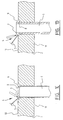
- FIG. 1A shows a cross sectional overview of a so called "seal weld” known from the art.
- This figure shows a tube 1 located in a bore of a tubesheet 2.
- the end 3 of the tube 1 is melted together with the tubesheet 2 by the weld arc 4.
- the weld 5 is formed by a single passage of the weld arc, whereby mostly just a little amount of weld-filler material is added or none at all.
- this weld detail is popular because of the relatively low costs for machining, it has the disadvantage that the weld penetration is relatively small, which makes that the leak path is in principle also relatively small.
- Figure 1B shows an alternative "seal weld".
- the tubesheet 2 is provided with a circular incision 6 around the bore.
- the incision 6 ensures a larger weld penetration.
- the tubesheet gets less change on distortion by weld-shrinkage-forces, due to the fact that these forces more easily can be reduced by relaxation.
- the appliance of a stringent set of weld parameters such as velocity, current, voltage stays very important to ensure that a sufficient leak path is obtained.
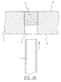
- Figure 1C shows a so called "strength weld".
- the tube 1 is located in the bore of a tubesheet 2.
- the end of the bore is enlarged relative to the rest of the bore.
- the tube 1 is fitted into the bore up to the enlarged section of the bore.
- the tube end 3 is melted together with the tubesheet by the weld arc 4 under suppliance of weld-filler-material by supply means 7.
- the welding is performed by two weld passages, of which formation of the root layer 8 is the most critical part of the welding process.
- the benefit of this weld detail opposed to those shown in figures 1A and 1B, is that the leak path can be better controlled.
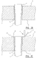
- Figure 1D shows a so called “fillet weld” which is only applicable for relatively thick tubes, to avoid that the weld arc punctures the wall of the tube.
- the tube 1 is located in the bore of the tubesheet 2, such that it protrudes with its end 3 above the second surface 11 of the tubesheet 2. Again the end of the bore of the tubesheet 2 is enlarged and the weld connections 8,9 are made in two welding passages in the enlarged part of the bore.
- formation of the root layer 8 is the most critical part of the welding process.
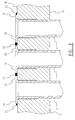
- figure 2A shows a tubesheet 2 with a first surface 10 and a second surface 11.
- the tubesheet 2 is provided with a bore 12, in which a screw thread 13, serving as a groove, is formed.
- the screw thread 13 starts from the first surface 10 and extends in the axial direction of the bore 12 towards the second surface 11.
- the axial length of the screw thread is shorter than the axial length of the bore.
- a tube 1 with an external diameter, that enables it to be placed in the bore 12 with a loose fit, is provided and placed in the bore by moving it in the direction of the arrow.
- Figure 2B shows the position of the tube 1 in the bore 12 of the tubesheet 2, after it has been expanded to fit tightly in a portion of the bore, which portion is shorter then the axial length of the groove 13.
- the end 3 of the tube 1 protrudes above the first surface 10 of the tubesheet 2.
- the end of the bore in this situation is relatively unworked. However, it may be rounded of or have a trumpet, cone or a combined trumpet-cone shape.
- the tube 1 remains to have a loose fitting in the bore on the side nearer to the second surface 11, there remains a connection 14 with the groove 13.
- Figure 2C shows the next step in the method according to the invention.
- the protruding end 3 of the tube 1 is flared, whereby a flare 20 is formed.
- the welded connection is made with the weld arc 4 under suppliance of filler material by supply means 7.
- Figure 3 shows a cross sectional overview along the lines III-III as shown in figure 4 of a preferred embodiment of the device according to the invention.
- the remaining unexpanded part of the tube is expanded to provide a tight fit of the tube 1 in the bore 12.
- the connection 14 is closed off.
- the bores 12 in the tubesheet 2 are provided at a distance such that the flares 20 come in such proximity of each other that adjacent welds 22 overlap.
- a continuous surface is formed by the flares 20 and the overlapping welds 22. This surface may be ground to an even surface and further polished to a smooth surface (not shown in figure 3) .
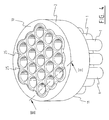
- Figure 4 shows a plan overview of a preferred embodiment of the device according to the invention.
- the device contains multiple tubes 1 connected to a tubesheet 2.
- a continuous surface 25 which is slightly elevated, is formed by the flares and the welded connections.
- the continuous surface 25 is ground and polished to an even and smooth surface.
- the continuous surface 25 may serve as a cladding layer, as it fully covers the first surface 10 of the tube plate 2 located directly underneath it. The remaining uncovered part of the first surface may be covered by a different material to protect it from corrosion.
- the device shown in figure 4 maybe applied in a heat exchanger.
Landscapes
- Engineering & Computer Science (AREA)
- Physics & Mathematics (AREA)
- Thermal Sciences (AREA)
- Mechanical Engineering (AREA)
- General Engineering & Computer Science (AREA)
- Butt Welding And Welding Of Specific Article (AREA)
- Lining Or Joining Of Plastics Or The Like (AREA)
Abstract
Description
- The present invention according to a first aspect relates to a method for performing a welded connection between a tubesheet and at least one tube.
- According to a second aspect the present invention relates to a device produced by the method according to the invention. Such a device finds application in e.g. a heat exchanger. However, a useful application in other technical fields is not excluded.
- In related heat exchangers there is an exchange in heat between the medium that runs through the tubes and the medium flowing at the outer side of the tubes. To ensure that these two media are separated and remain to be so seperated from each other, adequate tube to tubesheet connections have to be executed.
- In those cases in which the usage of the heat exchanger requires extra certainty that the tube-tubesheet connections will be leak tight, tubes are welded to the tubesheet.
- An important property of the welded connection is that the welds must provide a sufficiently long leak path. The person skilled in the art will be familiar with the term leak path, being the shortest way of the end of the crevice between tube and bore to the medium inside the tube seen through the weld.
- The weld-connections provided previously exhibited the property that a weld-connection was made by melting the edge of the tubesheet-borezone together with the relatively thin tube-ends, which operation is very critical in terms of amongst others a) fulfilment of specified minimum leak path at all weldpositions, b) avoiding damage or penetration of the tube end by e.g. a welding-arc, c) avoiding the blocking of a centering-device, used for automated welding, at removal due to a narrowing of the tube diameter caused by the weld, etcetera.
- A specific method and device according to prior art are known from
US-A-3.841.938 , which disclosure is reflected in the preambles ofindependent claims - In the method according to the invention a groove is provided in the corresponding bore, which groove extends from the first surface in the axial direction of the bore over at least a portion of the axial length thereof. In such an embodiment the tube has a tight fit in the bore, in the part where the groove is located, over a distance shorter then the axial length of the groove. The groove can be made in any form. A suitable form for making the groove is by making a screw thread. This because making a screw thread is a technique which is well known and for which many suitable devices are available. The inventive function of the groove is to provide an open channel for a fluid between the second surface and the first surface despite the tight fit of the pipe in at least a part of the bore over a distance shorter then the axial length of the groove. Further it is note here that an internal screw thread shaped groove in the bore can be employed in combination with an external screw thread on the outer surface of the tube to provide a mechanical interconnection between the tube sheet in the bore and the tube. The tube can then be screwed into the bore, and in such an embodiment the open channel can still be realised, provided the screwed interconnection is sufficiently loose to allow passage of expanding gasses and sufficiently fixed at the same time to allow for subsequent flaring and/or welding without the risk of misalignment of the tubes and the tube sheet during flaring and/or welding.
- The presence of a groove in or on the internal surface of the bore prevents blowing up of the weld material during welding, especially when closing the weld around the flare, as there remains an open channel between the bore and the tube leading to the second surface, along which channel any gas near the area subjected to welding, that expands as a result of the heat generated by the welding operation, can escape. In an embodiment, wherein the tube is expanded, the groove can also perform the function of providing a suitable grip for the expanded tube, without closing the open channel. Even if the groove does not extend through the bore, all the way to the second surface, the channel is not closed in an embodiment, wherein the tube is expanded only over a distance from the first surface, which distance is shorter than the length of the groove.
- The groove or at least the open channel also makes it possible to conduct pressure using Non-Destructive Testing (NDT) to test if the welded connection of the tube to the sheet is sufficient leak tight. Examples of such pressure using NDT methods are the so called "soap test", a Helium leak test, and a pressure test. As these NDT methods are known to the skilled person they will be discussed below only briefly.
- A suitable NDT method is the soap test in which a light air-over pressure is made around the tubes on the side of the second surface. The welds are than provided with a soap solution. On leaking, soap bubbles will develop which show the leak position.
- Another suitable NDT is the He-leak test. In this test a light over-pressure of Helium gas is applied around the tubes on the side of the second surface. Subsequently the welded connections are sniffed with special equipment, which is able to detect break trough of the very penetrable helium.
- A third suitable NDT is the pressure test. With this test water pressure is applied around the tubes on the side of the second surface. The level of the water pressure is related to the design pressure of the tube-tubesheet assembly. During the test the pressure is monitored and leakage is detected by any observed pressure drop event or any visual leakage.
- In the method according to the invention the weld arc is aimed on the circumference of the flare and tubesheet itself, at a distance, e.g. several millimeters away, from the edge of the tubesheet-bore zone. This makes the welding operation far less critical.
- In the method according to the invention the leak path is freely and better controllable opposed to the traditional welding details. This because the size of the welded connection is freely controllable as the weld arc is aimed at the circumference of the flare and the tubesheet itself.
- Due to the fact that the weld-arc is now aimed at the circumference of the flare and the tubesheet, damage or penetration of the tube-end is less likely to occur. Also the possibility of a centering device getting blocked in the tube is avoided, as the welded connection does not influence the tube diameter.
- Furthermore, the new method according to the invention provides benefits for execution of re-tubing. Re-tubing is some times executed to replace leaking tubes of a heat exchanger. Such leakage may occur after prolonged operation of the heat exchanger. Especially when operated under harsh conditions (e.g. very corrosive media).
- In the re-tubing execution of the tubes connected to the tubesheet with the traditional weld details it is often necessary to clean up the bores due to local contamination that easily may influence the welding process in a negative way. Such clean up is normally executed by grinding the inner surface of the bores. Thus the diameter of the bores may run out of tolerance which influences the fit of the new tubing.
- With the method according to the present invention retubing of a heat exchanger does not require cleaning of the bores in order to remove contaminations. It is sufficient to grind the first surface of the tubesheet to remove any contamination which might be present.
- In the method according to the invention a tubesheet with a first surface and a second surface is provided. The tubesheet can be formed by any material which can be subjected to a welding operation and which has suitable properties for the intended use. A selection of a suitable material is within the knowledge of the skilled person. Examples of suitable materials can be selected from metals and metal alloys, such as (stainless) steel, nickel (alloys), copper (alloys), titanium (alloys), zirconium. The material of the tubesheet may be cladded or coated with a material which is more corrosion resistant then the base material wherein cladding or coating may be executed prior or subsequent to assembly with the tube(s). Suitable cladding materials may me selected from the group consisting of stainless steel, nickel (alloys), copper (alloys), titanium (alloys).
- The tubesheet is provided with a number of bores extending from the first surface to the second surface. These bores can be circular, in correspondence with the tubes, but these tubes may have any other desired shape or form in transverse section, e.g. rectangular, along with the bores. Within this specification and the claims it is to be understood that the wording "a number of" refers to at least one, viz. one or more, in all instances that it is used. The bores can be provided by any suitable technique known to the skilled person such as drilling. Preferably the bore has a diameter, shape, form or other dimensions, which enables standard tubes to be placed in the bore. The selection of suitable diameters, shapes, forms or dimensions of the bore in connection with the tubing used is within the knowledge of the skilled person. Suitable guides are given in tables RCB-7.41 and RCB-7.41 M of the eight edition of the standards of the Tubular Exchanger Manufacturers Association.
- The number of tubes provided in the method according to the invention have an exterior diameter, shape, form or other dimension, which enables the tube to be placed in a bore. This can be either with a tight fit, a loose fit, or a temperature dependent fit. A temperature dependant fit can be reached by cooling the pipe prior to fitting it into the bore, or heating the tubesheet prior to fitting the tube into the bore. Preferably the tube is of a type which is commercially readily available. It is to be understood that the invention is not limited to the use of a specific type of tube.
- The provided tubes are made from a pliable material, which enables them to be flared at their ends. Any pliable material can be used, as long as it can be subjected to a welding operation as well as deformation or other operation to provide a flare. The selection of suitable materials is within the knowledge of the skilled person. Examples of suitable materials can be selected from the group comprising metals, metal alloys, such as (stainless) steel, nickel (alloys), copper (alloys), titanium (alloys), zirconium.
- Flaring of the end of the protruded portion of the tube can be done by any suitable methods known to the skilled person, e.g. by using a flaring tool. Preferably the flares are made by hydraulic pressing or forming.
- It must be understood that if the other end of a tube is freely movable through the bore, flaring can be done before a tube is placed in the bore. If the other end of a tube does not permit passage through the bore, flaring will be done after the tube is placed in a bore.
- The welded connection between the tubesheet and each tube, is made at the circumference of each flare. The welded connection can be made by using known welding techniques and equipment. It is possible to make the welded connection in a single passage of the weld arc around the circumference of the flare. During such a single welding passage the material of the tube and the tubesheet is melted together. During such a single welding passage preferably welding material is deposited to strengthen the welded connection. In addition to this in the method according to the present invention deposition of weld material will increase the leak path. However, such deposition of weld material is not strictly obligatory since for some applications the melting operation will provide a welded connection with sufficient strength and leak path.
- It is also possible to use multiple welding passages, such as two or three or more welding passages. Such additional welding passages can be used to further strengthen the welded connection. When multiple welding passages are used, all welding passages can be similar or different welding modes can be used. For instance, when two welding passages are used, the first welding passage can be used to prepare the path for the second welding passage by e.g. evening it to provide a smooth surface. In such a case the first welding passage only melts the material of the tubesheet and the tube together, and none or little filler material is deposited. During the second subsequent welding passage, welding material is deposited.
- After the second welding passage it is possible to use a third welding passage in order to melt the deposited welding material in order to improve the weld shape. The use of such a third weld passage may provide a welded connection with a flattened surface. If electric welding is used preferably the third welding passage is then performed with a higher voltage than the previous welding passages.
- According to a preferred embodiment of the method according to the invention, the flares are provided with a trumpet shape or a cone shape. It is also possible that the form of the flare is a combination of a cone shape and a trumpet shape. In such a case the trumpet shape is located closer to the circumference of the flare, then the cone shape. The trumpet shape or cone shape or the combined trumpet-cone shape of the flare provides a smooth flow of a fluid medium when accessing or leaving the pipe.
- According to a different preferred embodiment of the method according to the invention the end of the bore at the first surface is rounded and/or has the shape of a cone. Such a shape of the bore end facilitated flaring the tube in a trumpet shape, a cone shape or a combined trumpet-cone shape.
- A preferred embodiment of the method according to the invention comprises: mechanically interconnecting the tube and the tube sheet at the latest prior to welding the flared protruding end portion of the tube, thus providing a preliminary positional fixation of the tube and the tube plate relative to one another to be maintained during at least one of the operations of flaring the protruding end portion of the tube and welding the flare to the tube sheet. As a consequence the mutual positioning of the tubes and the tube sheet is ensured, even when during subsequent operations like flaring and welding the relative mutual positioning may be endangered without the said mechanical fixation. In such an embodiment, especially when the provided tube has a loose fit in the bore, it is preferred to expand the tube to fit tightly in at least a part of the bore. This operations is performed preferably prior to performing the flaring operation on the end of the tube or at least (at the latest) prior to welding. The expanded tight fit of the tube in at least a part of the bore fixates the tube in the bore which is beneficial for the flaring operation and/or the welding operation.
- After performing the pressure-using NDT method or at least establishing the interconnection, the remaining part of the tube not having a tight fit in the bore may be fitted tightly in the bore. This can be done by e.g. expanding the part of the tube not having a tight fit to fit tightly in the bore. During the expanding operation care is taken to avoid expanding of any part of the tube located outside the bore. In practice this can be achieved by not expanding the remaining 2-7 mm e.g. 5 mm of the tube located in the bore near the second surface. Hereby the channel formed by the groove is closed off. This provides additional sealing of the tube to tubesheet connection.
- When more than one pipe and more than one bore are provided, it is beneficial if the bores are provided at such a distance of each other, that when the ends of the pipes are flared, the circumferences of the flares come in such proximity of each other that the welded connection at adjacent flares overlap. In this way a continuous surface is formed by the flares and the welded connections. Such a continuous surface forms a coverage over the tubesheet and can have the function of a cladding layer. Thus in applications in which the use of a cladded material for the tubesheet is suitable, the cladding layer may be formed by the continuous surface formed by the flares of the tubes and the welded connections. Any part of the tubesheet not covered by the continuous surface may be cladded in the usual way, or otherwise covered with a protective layer.
- In order to form a smooth surface, the continuous surface formed by the flares and the welded connections is ground to a smooth surface and preferably subsequently polished. The presence of such a smooth continuous surface is beneficial in special applications wherein it is undesired if surface imperfections e.g. crevices etc. are present on the surface of the tubesheet. This e.g. provides a better septic quality of the tubesheet and in particular the tubesheet-bore-zone.
- The present invention relates also to a device produced in accordance with the method of the invention. The device according to the invention finds application in heat exchangers, although other applications are not excluded.
- In a preferred embodiment of the device according to the invention a groove is located in the surface of the bore, which groove extends from the first surface in the axial direction of the bore for at least a portion of the axial length of the bore. In this case the tube can have a tight fit in the bore, in the part where the groove is located, over a distance shorter then the axial length of the groove. The function of the groove is providing an open channel for a fluid between the second and first surfaces, despite the tight fit of the pipe in at least a part of the bore over a shorter distance than the axial length of the groove.
- The presence of such a groove in the surface of the bore makes it possible to conduct pressure using Non-Destructive Testing (NDT) to test if the welded connection of the tube to the tubesheet is sufficient leak tight. Examples of such pressure using NDT methods have been discussed above.
- It will be evident to the skilled person that the embodiment of the device according to the invention wherein there remains an open channel between the first surface and the second surface is not (optimally) suited for use in a heat exchanger. However, this embodiment is possibly or optionally an important intermediate state in the production of a heat exchanger on which pressure using NDT methods can be performed. In order to make this embodiment of the device suitable for the application in a heat exchanger it is of importance to ensure that the tube has a tight fit over substantially the full axial length of the bore. If the tight fit of the tube in the bore is obtained by expanding the tube in the bore, in practice the remaining 2-7 mm e.g. 5 mm of the tube located in the bore near the second surface will remain unexpanded to prevent that any part of the tube located outside the bore is expanded.
- The groove can have any form. A suitable form of the groove is a screw thread. This because making a screw thread is a technique which is well known and for which many suitable devices are available.
- According to a preferred embodiment of the device according to the invention, the flares are provided with a trumpet shape or a cone shape. It is also possible that the form of the flare is a combination of a cone shape and a trumpet shape. In such a case the trumpet shape is located closer to the circumference of the flare, than the cone shape. The trumpet shape or cone shape or the combined trumpet-cone shape of the flare provides a smooth flow of a fluid medium when accessing or leaving the tube.
- According to a different preferred embodiment of the device according to the invention the end of the bore at the first surface is rounded and/or has the shape of a cone. Such a shape of the bore end facilitates flaring the tube in a trumpet shape, a cone shape or a combined trumpet-cone shape.
- It is preferred that the tube has a tight fit in at least a part of the bore. The tight fit of the tube in at least a part of the bore fixates the tube in the bore which is beneficial for the flaring operation and/or the welding operation. Furthermore, the tight fit provides additional sealing of the tube to tubesheet connection.
- In a preferred embodiment of the device according to the invention more then one bore and more then one tube are provided and the welded connections between adjacent flares overlap. This embodiment of the device according to the invention comprises a continuous surface formed by the flares and the welded connections. Such a continuous surface forms a coverage over the tubesheet and can have the function of a cladding layer. Thus in application in which the use of a cladded material for the tubesheet is suitable, the cladding layer may be formed by the continuous surface formed by the flares of the tubes and the welded connections. Any part of the tubesheet not covered by the continuous surface may be cladded in the usual way, or otherwise covered with a protective layer.
- Preferably the continuous surface is an even and smooth surface. Such an even and smooth surface is beneficial in special applications wherein it is undesired if surface imperfections such as crevices etc. are present on the surface of the tubesheet. This e.g. provides a better septic quality of the tubesheet, in particular the tubesheet-borezone.
- The invention will be further explained with reference to the figures showing non-limiting embodiments of the invention.
- Figures 1A-1D show cross sectional overviews of welded tubesheet to tube connections according to the prior art.
- Figures 2A-2C show cross sectional overviews of different stages of the method according to the invention.
- Figure 3 shows a cross sectional overview along the line III-III in fig. 4 of a preferred embodiment of the device according the invention.
- Figure 4 shows a plan overview of a preferred embodiment of the device according to the invention.
- Figure 1A shows a cross sectional overview of a so called "seal weld" known from the art. This figure shows a
tube 1 located in a bore of atubesheet 2. Theend 3 of thetube 1 is melted together with thetubesheet 2 by theweld arc 4. In this weld detail theweld 5 is formed by a single passage of the weld arc, whereby mostly just a little amount of weld-filler material is added or none at all. Although this weld detail is popular because of the relatively low costs for machining, it has the disadvantage that the weld penetration is relatively small, which makes that the leak path is in principle also relatively small. - Figure 1B shows an alternative "seal weld". In this alternative the
tubesheet 2 is provided with a circular incision 6 around the bore. The incision 6 ensures a larger weld penetration. Moreover it effects that the tubesheet gets less change on distortion by weld-shrinkage-forces, due to the fact that these forces more easily can be reduced by relaxation. The appliance of a stringent set of weld parameters such as velocity, current, voltage stays very important to ensure that a sufficient leak path is obtained. - Figure 1C shows a so called "strength weld". The
tube 1 is located in the bore of atubesheet 2. The end of the bore is enlarged relative to the rest of the bore. Thetube 1 is fitted into the bore up to the enlarged section of the bore. Thetube end 3 is melted together with the tubesheet by theweld arc 4 under suppliance of weld-filler-material bysupply means 7. Usually the welding is performed by two weld passages, of which formation of theroot layer 8 is the most critical part of the welding process. The benefit of this weld detail opposed to those shown in figures 1A and 1B, is that the leak path can be better controlled. - Figure 1D shows a so called "fillet weld" which is only applicable for relatively thick tubes, to avoid that the weld arc punctures the wall of the tube. The
tube 1 is located in the bore of thetubesheet 2, such that it protrudes with itsend 3 above thesecond surface 11 of thetubesheet 2. Again the end of the bore of thetubesheet 2 is enlarged and theweld connections root layer 8 is the most critical part of the welding process. - Now turning to a preferred embodiments of the present invention, figure 2A shows a
tubesheet 2 with afirst surface 10 and asecond surface 11. Thetubesheet 2 is provided with abore 12, in which ascrew thread 13, serving as a groove, is formed. Thescrew thread 13 starts from thefirst surface 10 and extends in the axial direction of thebore 12 towards thesecond surface 11. The axial length of the screw thread is shorter than the axial length of the bore. Atube 1 with an external diameter, that enables it to be placed in thebore 12 with a loose fit, is provided and placed in the bore by moving it in the direction of the arrow. - Figure 2B shows the position of the
tube 1 in thebore 12 of thetubesheet 2, after it has been expanded to fit tightly in a portion of the bore, which portion is shorter then the axial length of thegroove 13. As shown, theend 3 of thetube 1 protrudes above thefirst surface 10 of thetubesheet 2. The end of the bore in this situation is relatively unworked. However, it may be rounded of or have a trumpet, cone or a combined trumpet-cone shape. As thetube 1 remains to have a loose fitting in the bore on the side nearer to thesecond surface 11, there remains aconnection 14 with thegroove 13. Thus there is a free channel for passage of a fluid going from the second surface to thefirst surface 10. - Figure 2C shows the next step in the method according to the invention. As is shown, the
protruding end 3 of thetube 1 is flared, whereby aflare 20 is formed. At thecircumference 21 of the flare, the welded connection is made with theweld arc 4 under suppliance of filler material bysupply means 7. - Figure 3 shows a cross sectional overview along the lines III-III as shown in figure 4 of a preferred embodiment of the device according to the invention. As is shown the remaining unexpanded part of the tube is expanded to provide a tight fit of the
tube 1 in thebore 12. Thereby theconnection 14 is closed off. As is also shown, thebores 12 in thetubesheet 2 are provided at a distance such that theflares 20 come in such proximity of each other thatadjacent welds 22 overlap. Thus, a continuous surface is formed by theflares 20 and the overlapping welds 22. This surface may be ground to an even surface and further polished to a smooth surface (not shown in figure 3) . - Figure 4 shows a plan overview of a preferred embodiment of the device according to the invention. The device contains
multiple tubes 1 connected to atubesheet 2. At thefirst surface 10 of thetubesheet 2, acontinuous surface 25, which is slightly elevated, is formed by the flares and the welded connections. Thecontinuous surface 25 is ground and polished to an even and smooth surface. Thecontinuous surface 25 may serve as a cladding layer, as it fully covers thefirst surface 10 of thetube plate 2 located directly underneath it. The remaining uncovered part of the first surface may be covered by a different material to protect it from corrosion. The device shown in figure 4 maybe applied in a heat exchanger.
Claims (18)
- Method for forming a connection between a tube sheet and at least one tube comprising:- providing a tube sheet (2) with a first surface (10) and a second surface (11) and a number of bores (12) extending from the first surface to the second surface,- providing the tube (1) of a pliable material with an exterior shape and dimensions, which enable the tube to be accommodated in a corresponding bore;- placing the tube in the corresponding bore, such that an end portion of the tube protrudes from the side of the first surface of the tube sheet;- flaring the protruding end portion of the tube, to form a flare (20); and- making a welded connection between the tube sheet and the tube at the circumference (21) of the flare,CHARACTERISED BY- providing a groove (13) in the corresponding bore from the first surface in the axial direction of the bore over at least a portion of the axial length thereof.
- Method according to claim 1, wherein interconnecting comprises: expanding the tube to fit tightly in at least a part of the corresponding bore accommodating the tube.
- Method according to claim 2, comprising: expanding the tube prior to flaring thereof.
- Method according to any one of claims 1-3, wherein the tube accommodated in the bore is expanded over a distance shorter than the axial length of the groove (13) located in the bore accommodating the tube.
- Method according to any one of claims 1-4, further comprising testing a welded connection by means of a pressure using non-destructive testing method, that is selected from the group comprising a soap test, a He-leak test, a water pressure test.
- Method according to any one of claims 1-5, further comprising expanding any remaining, previously unexpanded part in the bore (14) of the tube over substantially the full axial length of the bore wherein the tube is accommodated.
- Method according to claim 6, comprising expanding the any remaining, previously unexpanded part of the tube after testing of the welded connection.
- Method according to any one of claims 1-7, wherein the groove is provided in the form of a screw thread (13).
- Method according to any one of claims 1-8, wherein more than one pipe and more than one bore in the tube sheet are provided, which bores are provided at a distance from each other, further comprising: dimensioning the protruding end portions of the tubes and thus the flares, to approximate the circumferences of the flares to one another, whereby the welded connections at adjacent flares overlap.
- Method according to any one of claims 1-9, further comprising grinding the surface formed by the flare and the welded connection to a smooth surface and preferably polishing the smooth surface.
- Device comprising:- a tubesheet (2) with a first surface (10) and a second surface (11) and a number of bores (12) extending from the first surface to the second surface,- at least one tube (1) of a pliable material placed in a corresponding bore, wherein the tube has a flared portion (20) on the side of the first surface, which flared portion is weld-connected at its circumference (21) to the first surface of the tube sheet,CHARACTERISED IN THAT
a groove (13) is provided in the corresponding bore, which groove extends from the first surface in the axial direction of the bore over at least a portion of the axial length thereof. - Device according to claim 11, wherein the tube is expanded to fit tightly in at least a part of the corresponding bore accommodating the tube.
- Device according to claim 12, wherein the tube is expanded prior to flaring thereof.
- Device according to any one of claims 11-13, wherein the tube accommodated in the bore is expanded over a distance shorter than the axial length of the groove (13) located in the bore accommodating the tube.
- Device according to claim 14, wherein any remaining unexpanded part in the bore (14) of the tube is expanded over substantially the full axial length of the bore wherein the tube is accommodated, after realising the welded connection.
- Device according to any one of claims 11-15, wherein the groove is provided in the form of a screw thread (13).
- Device according to any one of claims 11-16, wherein more than one pipe and more than one bore in the tube sheet are provided, which bores are provided at a distance from each other, wherein the protruding end portions of the tubes and thus the flares are dimensioned to approximate the circumferences of the flares to one another, whereby the welded connections at adjacent flares overlap.
- Device according to any one of claims 11-17, further comprising grinding the surface formed by the flare and the welded connection to a smooth surface and preferably polishing the smooth surface.
Priority Applications (7)
| Application Number | Priority Date | Filing Date | Title |
|---|---|---|---|
| EP04075261A EP1559983B1 (en) | 2004-01-28 | 2004-01-28 | Method for forming a welded connection between a tubesheet and a number of tubes and a device produced by such method |
| AT04075261T ATE371157T1 (en) | 2004-01-28 | 2004-01-28 | METHOD FOR WELDING PIPES TO A TUBE BASE AND DEVICE PRODUCED BY SUCH METHOD |
| DE602004008410T DE602004008410T2 (en) | 2004-01-28 | 2004-01-28 | A method of welding pipes with a tube sheet and a device produced by such a method |
| PCT/EP2005/000952 WO2005075923A1 (en) | 2004-01-28 | 2005-01-28 | Method for forming a welded connection between a tubesheet and a number of tubes and a device produced by such method |
| PCT/EP2005/000953 WO2005075924A1 (en) | 2004-01-28 | 2005-01-28 | Method for forming a welded connection between a tubesheet and a number of tubes and a device produced by such method |
| DE602005000933T DE602005000933T2 (en) | 2004-01-28 | 2005-01-28 | METHOD FOR PRODUCING A WELDED CONNECTION BETWEEN A TUBE AND MULTIPLE TUBES AND DEVICE PRODUCED BY SUCH A METHOD |
| EP05701286A EP1709383B1 (en) | 2004-01-28 | 2005-01-28 | Method for forming a welded connection between a tubesheet and a number of tubes and a device produced by such method |
Applications Claiming Priority (1)
| Application Number | Priority Date | Filing Date | Title |
|---|---|---|---|
| EP04075261A EP1559983B1 (en) | 2004-01-28 | 2004-01-28 | Method for forming a welded connection between a tubesheet and a number of tubes and a device produced by such method |
Publications (2)
| Publication Number | Publication Date |
|---|---|
| EP1559983A1 EP1559983A1 (en) | 2005-08-03 |
| EP1559983B1 true EP1559983B1 (en) | 2007-08-22 |
Family
ID=34639449
Family Applications (2)
| Application Number | Title | Priority Date | Filing Date |
|---|---|---|---|
| EP04075261A Expired - Lifetime EP1559983B1 (en) | 2004-01-28 | 2004-01-28 | Method for forming a welded connection between a tubesheet and a number of tubes and a device produced by such method |
| EP05701286A Not-in-force EP1709383B1 (en) | 2004-01-28 | 2005-01-28 | Method for forming a welded connection between a tubesheet and a number of tubes and a device produced by such method |
Family Applications After (1)
| Application Number | Title | Priority Date | Filing Date |
|---|---|---|---|
| EP05701286A Not-in-force EP1709383B1 (en) | 2004-01-28 | 2005-01-28 | Method for forming a welded connection between a tubesheet and a number of tubes and a device produced by such method |
Country Status (4)
| Country | Link |
|---|---|
| EP (2) | EP1559983B1 (en) |
| AT (1) | ATE371157T1 (en) |
| DE (2) | DE602004008410T2 (en) |
| WO (2) | WO2005075923A1 (en) |
Cited By (1)
| Publication number | Priority date | Publication date | Assignee | Title |
|---|---|---|---|---|
| US10782500B1 (en) | 2019-10-25 | 2020-09-22 | Afl Telecommunications Llc | Fiber optic furcation units, kits, and methods |
Families Citing this family (4)
| Publication number | Priority date | Publication date | Assignee | Title |
|---|---|---|---|---|
| KR100869896B1 (en) | 2007-07-05 | 2008-11-24 | 한국가스공사 | Integrity test method of tube bundle in gas heater |
| US9039814B2 (en) * | 2013-04-18 | 2015-05-26 | Saes Pure Gas, Inc. | System and method for welding a plurality of small diameter palladium alloy tubes to a common base plate in a space efficient manner |
| EP3742099B1 (en) * | 2019-05-23 | 2021-11-03 | Valeo Termico S.A. | A heat exchanger |
| CN113996964B (en) * | 2021-12-30 | 2022-03-18 | 常州新海飞金属制品有限公司 | Tube plate welding method, tube body and tube plate connecting method and heat exchanger |
Family Cites Families (9)
| Publication number | Priority date | Publication date | Assignee | Title |
|---|---|---|---|---|
| US1583758A (en) * | 1923-04-09 | 1926-05-04 | Winslown Safety Highpressure B | Method of constructing boilers |
| US2405399A (en) * | 1943-09-22 | 1946-08-06 | Bugg | Tube beading and expanding tool and method |
| BE462335A (en) * | 1945-01-30 | |||
| US3207215A (en) * | 1961-06-02 | 1965-09-21 | Raypak Inc | Heat exchanger |
| US3258067A (en) * | 1964-06-01 | 1966-06-28 | Fleur Corp | Heat exchanger |
| US3628923A (en) * | 1968-10-24 | 1971-12-21 | Texas Instruments Inc | Method of making header joint for a clad tubulation |
| DE2204167A1 (en) * | 1972-01-29 | 1973-08-09 | Krupp Gmbh | HEAT EXCHANGER AND PROCESS FOR ITS MANUFACTURING |
| US3979810A (en) * | 1974-11-30 | 1976-09-14 | Balcke-Durr Aktiengesellschaft | Method of hermetically swaging tubes into tube plates |
| JPS61216821A (en) * | 1985-03-20 | 1986-09-26 | Hitachi Ltd | Fixing method of thin plate and pipelike member |
-
2004
- 2004-01-28 EP EP04075261A patent/EP1559983B1/en not_active Expired - Lifetime
- 2004-01-28 DE DE602004008410T patent/DE602004008410T2/en not_active Expired - Lifetime
- 2004-01-28 AT AT04075261T patent/ATE371157T1/en not_active IP Right Cessation
-
2005
- 2005-01-28 WO PCT/EP2005/000952 patent/WO2005075923A1/en active IP Right Grant
- 2005-01-28 WO PCT/EP2005/000953 patent/WO2005075924A1/en active Application Filing
- 2005-01-28 EP EP05701286A patent/EP1709383B1/en not_active Not-in-force
- 2005-01-28 DE DE602005000933T patent/DE602005000933T2/en active Active
Cited By (1)
| Publication number | Priority date | Publication date | Assignee | Title |
|---|---|---|---|---|
| US10782500B1 (en) | 2019-10-25 | 2020-09-22 | Afl Telecommunications Llc | Fiber optic furcation units, kits, and methods |
Also Published As
| Publication number | Publication date |
|---|---|
| EP1709383B1 (en) | 2007-04-18 |
| EP1709383A1 (en) | 2006-10-11 |
| WO2005075924A1 (en) | 2005-08-18 |
| EP1559983A1 (en) | 2005-08-03 |
| DE602005000933D1 (en) | 2007-05-31 |
| DE602004008410T2 (en) | 2008-05-15 |
| WO2005075923A1 (en) | 2005-08-18 |
| DE602004008410D1 (en) | 2007-10-04 |
| DE602005000933T2 (en) | 2009-10-08 |
| ATE371157T1 (en) | 2007-09-15 |
Similar Documents
| Publication | Publication Date | Title |
|---|---|---|
| US4592577A (en) | Sleeve type repair of degraded nuclear steam generator tubes | |
| JP5227154B2 (en) | Method for joining tubesheet and tube and friction tool for carrying out this method | |
| US4739916A (en) | Sleeve repair of degraded nuclear steam generator tubes | |
| EP1709383B1 (en) | Method for forming a welded connection between a tubesheet and a number of tubes and a device produced by such method | |
| CN110582370A (en) | Method for manufacturing liquid cooling jacket | |
| TW201341700A (en) | Steam generator heating tube repair means and repair method | |
| US4943001A (en) | Tube-type vessel having crevice-free joints and method for manufacturing the same | |
| EP1373774B1 (en) | Method of laying pipe-in-pipe structures and device for use therein | |
| JPH0220880B2 (en) | ||
| JPH05157487A (en) | Method of exchanging tube of straight tube type heat exchanger | |
| JP7462392B2 (en) | Plate Heat Exchanger | |
| US9989182B2 (en) | Method of forming a sealed joint between a tubular article and a sheet article | |
| JPS63153398A (en) | Method of repairing or protecting terminal of metallic heat exchanging tube and sleeve used for said method | |
| CN101628354B (en) | Bore welding method of heat exchange tube and tube plate in heat exchanger | |
| JP2016138731A (en) | Heat exchanger | |
| EP3044488B1 (en) | Valve housing with a spindle guide and method for production thereof | |
| JPH06341576A (en) | Bayonet joint particularly for metallic pipe for fluid | |
| JP2012187623A (en) | Method for welding tube | |
| KR200389186Y1 (en) | Joint for pipe | |
| RU2128098C1 (en) | Method for joining tubes with tube plate | |
| CN210464172U (en) | Oil cooler end mounting structure and oil cooler | |
| KR100380290B1 (en) | fixed structure and molding method for nozzle sleeve | |
| US4229869A (en) | Method of repairing aluminum plate fin coils | |
| JPH08152290A (en) | Method for welding different metals and welded structure thereof | |
| JP7132283B2 (en) | How to disassemble a steam generator |
Legal Events
| Date | Code | Title | Description |
|---|---|---|---|
| PUAI | Public reference made under article 153(3) epc to a published international application that has entered the european phase |
Free format text: ORIGINAL CODE: 0009012 |
|
| AK | Designated contracting states |
Kind code of ref document: A1 Designated state(s): AT BE BG CH CY CZ DE DK EE ES FI FR GB GR HU IE IT LI LU MC NL PT RO SE SI SK TR |
|
| AX | Request for extension of the european patent |
Extension state: AL LT LV MK |
|
| 17P | Request for examination filed |
Effective date: 20060111 |
|
| RAP1 | Party data changed (applicant data changed or rights of an application transferred) |
Owner name: MADIOEN HOLDING B.V. |
|
| AKX | Designation fees paid |
Designated state(s): AT BE BG CH CY CZ DE DK EE ES FI FR GB GR HU IE IT LI LU MC NL PT RO SE SI SK TR |
|
| 17Q | First examination report despatched |
Effective date: 20060328 |
|
| GRAP | Despatch of communication of intention to grant a patent |
Free format text: ORIGINAL CODE: EPIDOSNIGR1 |
|
| GRAS | Grant fee paid |
Free format text: ORIGINAL CODE: EPIDOSNIGR3 |
|
| GRAA | (expected) grant |
Free format text: ORIGINAL CODE: 0009210 |
|
| AK | Designated contracting states |
Kind code of ref document: B1 Designated state(s): AT BE BG CH CY CZ DE DK EE ES FI FR GB GR HU IE IT LI LU MC NL PT RO SE SI SK TR |
|
| REG | Reference to a national code |
Ref country code: GB Ref legal event code: FG4D |
|
| REG | Reference to a national code |
Ref country code: CH Ref legal event code: EP |
|
| REG | Reference to a national code |
Ref country code: IE Ref legal event code: FG4D |
|
| REF | Corresponds to: |
Ref document number: 602004008410 Country of ref document: DE Date of ref document: 20071004 Kind code of ref document: P |
|
| PG25 | Lapsed in a contracting state [announced via postgrant information from national office to epo] |
Ref country code: BG Free format text: LAPSE BECAUSE OF FAILURE TO SUBMIT A TRANSLATION OF THE DESCRIPTION OR TO PAY THE FEE WITHIN THE PRESCRIBED TIME-LIMIT Effective date: 20071122 Ref country code: FI Free format text: LAPSE BECAUSE OF FAILURE TO SUBMIT A TRANSLATION OF THE DESCRIPTION OR TO PAY THE FEE WITHIN THE PRESCRIBED TIME-LIMIT Effective date: 20070822 Ref country code: ES Free format text: LAPSE BECAUSE OF FAILURE TO SUBMIT A TRANSLATION OF THE DESCRIPTION OR TO PAY THE FEE WITHIN THE PRESCRIBED TIME-LIMIT Effective date: 20071203 |
|
| PG25 | Lapsed in a contracting state [announced via postgrant information from national office to epo] |
Ref country code: CH Free format text: LAPSE BECAUSE OF FAILURE TO SUBMIT A TRANSLATION OF THE DESCRIPTION OR TO PAY THE FEE WITHIN THE PRESCRIBED TIME-LIMIT Effective date: 20070822 Ref country code: AT Free format text: LAPSE BECAUSE OF FAILURE TO SUBMIT A TRANSLATION OF THE DESCRIPTION OR TO PAY THE FEE WITHIN THE PRESCRIBED TIME-LIMIT Effective date: 20070822 Ref country code: LI Free format text: LAPSE BECAUSE OF FAILURE TO SUBMIT A TRANSLATION OF THE DESCRIPTION OR TO PAY THE FEE WITHIN THE PRESCRIBED TIME-LIMIT Effective date: 20070822 |
|
| REG | Reference to a national code |
Ref country code: CH Ref legal event code: PL |
|
| EN | Fr: translation not filed | ||
| PG25 | Lapsed in a contracting state [announced via postgrant information from national office to epo] |
Ref country code: GR Free format text: LAPSE BECAUSE OF FAILURE TO SUBMIT A TRANSLATION OF THE DESCRIPTION OR TO PAY THE FEE WITHIN THE PRESCRIBED TIME-LIMIT Effective date: 20071123 Ref country code: DK Free format text: LAPSE BECAUSE OF FAILURE TO SUBMIT A TRANSLATION OF THE DESCRIPTION OR TO PAY THE FEE WITHIN THE PRESCRIBED TIME-LIMIT Effective date: 20070822 |
|
| PG25 | Lapsed in a contracting state [announced via postgrant information from national office to epo] |
Ref country code: CZ Free format text: LAPSE BECAUSE OF FAILURE TO SUBMIT A TRANSLATION OF THE DESCRIPTION OR TO PAY THE FEE WITHIN THE PRESCRIBED TIME-LIMIT Effective date: 20070822 Ref country code: PT Free format text: LAPSE BECAUSE OF FAILURE TO SUBMIT A TRANSLATION OF THE DESCRIPTION OR TO PAY THE FEE WITHIN THE PRESCRIBED TIME-LIMIT Effective date: 20080122 Ref country code: SK Free format text: LAPSE BECAUSE OF FAILURE TO SUBMIT A TRANSLATION OF THE DESCRIPTION OR TO PAY THE FEE WITHIN THE PRESCRIBED TIME-LIMIT Effective date: 20070822 |
|
| PLBE | No opposition filed within time limit |
Free format text: ORIGINAL CODE: 0009261 |
|
| STAA | Information on the status of an ep patent application or granted ep patent |
Free format text: STATUS: NO OPPOSITION FILED WITHIN TIME LIMIT |
|
| PG25 | Lapsed in a contracting state [announced via postgrant information from national office to epo] |
Ref country code: SE Free format text: LAPSE BECAUSE OF FAILURE TO SUBMIT A TRANSLATION OF THE DESCRIPTION OR TO PAY THE FEE WITHIN THE PRESCRIBED TIME-LIMIT Effective date: 20071122 Ref country code: RO Free format text: LAPSE BECAUSE OF FAILURE TO SUBMIT A TRANSLATION OF THE DESCRIPTION OR TO PAY THE FEE WITHIN THE PRESCRIBED TIME-LIMIT Effective date: 20070822 |
|
| 26N | No opposition filed |
Effective date: 20080526 |
|
| PG25 | Lapsed in a contracting state [announced via postgrant information from national office to epo] |
Ref country code: MC Free format text: LAPSE BECAUSE OF NON-PAYMENT OF DUE FEES Effective date: 20080131 |
|
| GBPC | Gb: european patent ceased through non-payment of renewal fee |
Effective date: 20080128 |
|
| PG25 | Lapsed in a contracting state [announced via postgrant information from national office to epo] |
Ref country code: GB Free format text: LAPSE BECAUSE OF NON-PAYMENT OF DUE FEES Effective date: 20080128 |
|
| PG25 | Lapsed in a contracting state [announced via postgrant information from national office to epo] |
Ref country code: EE Free format text: LAPSE BECAUSE OF FAILURE TO SUBMIT A TRANSLATION OF THE DESCRIPTION OR TO PAY THE FEE WITHIN THE PRESCRIBED TIME-LIMIT Effective date: 20070822 Ref country code: IE Free format text: LAPSE BECAUSE OF NON-PAYMENT OF DUE FEES Effective date: 20080128 |
|
| PG25 | Lapsed in a contracting state [announced via postgrant information from national office to epo] |
Ref country code: SI Free format text: LAPSE BECAUSE OF FAILURE TO SUBMIT A TRANSLATION OF THE DESCRIPTION OR TO PAY THE FEE WITHIN THE PRESCRIBED TIME-LIMIT Effective date: 20070822 |
|
| PG25 | Lapsed in a contracting state [announced via postgrant information from national office to epo] |
Ref country code: CY Free format text: LAPSE BECAUSE OF FAILURE TO SUBMIT A TRANSLATION OF THE DESCRIPTION OR TO PAY THE FEE WITHIN THE PRESCRIBED TIME-LIMIT Effective date: 20070822 |
|
| PG25 | Lapsed in a contracting state [announced via postgrant information from national office to epo] |
Ref country code: LU Free format text: LAPSE BECAUSE OF NON-PAYMENT OF DUE FEES Effective date: 20080128 Ref country code: HU Free format text: LAPSE BECAUSE OF FAILURE TO SUBMIT A TRANSLATION OF THE DESCRIPTION OR TO PAY THE FEE WITHIN THE PRESCRIBED TIME-LIMIT Effective date: 20080223 |
|
| PG25 | Lapsed in a contracting state [announced via postgrant information from national office to epo] |
Ref country code: TR Free format text: LAPSE BECAUSE OF FAILURE TO SUBMIT A TRANSLATION OF THE DESCRIPTION OR TO PAY THE FEE WITHIN THE PRESCRIBED TIME-LIMIT Effective date: 20070822 |
|
| PG25 | Lapsed in a contracting state [announced via postgrant information from national office to epo] |
Ref country code: IT Free format text: LAPSE BECAUSE OF NON-PAYMENT OF DUE FEES Effective date: 20080131 |
|
| PG25 | Lapsed in a contracting state [announced via postgrant information from national office to epo] |
Ref country code: FR Free format text: LAPSE BECAUSE OF FAILURE TO SUBMIT A TRANSLATION OF THE DESCRIPTION OR TO PAY THE FEE WITHIN THE PRESCRIBED TIME-LIMIT Effective date: 20080418 |
|
| PGFP | Annual fee paid to national office [announced via postgrant information from national office to epo] |
Ref country code: NL Payment date: 20170126 Year of fee payment: 14 |
|
| PGFP | Annual fee paid to national office [announced via postgrant information from national office to epo] |
Ref country code: DE Payment date: 20170125 Year of fee payment: 14 |
|
| PGFP | Annual fee paid to national office [announced via postgrant information from national office to epo] |
Ref country code: BE Payment date: 20170127 Year of fee payment: 14 |
|
| REG | Reference to a national code |
Ref country code: DE Ref legal event code: R119 Ref document number: 602004008410 Country of ref document: DE |
|
| REG | Reference to a national code |
Ref country code: NL Ref legal event code: MM Effective date: 20180201 |
|
| PG25 | Lapsed in a contracting state [announced via postgrant information from national office to epo] |
Ref country code: DE Free format text: LAPSE BECAUSE OF NON-PAYMENT OF DUE FEES Effective date: 20180801 |
|
| REG | Reference to a national code |
Ref country code: BE Ref legal event code: MM Effective date: 20180131 |
|
| PG25 | Lapsed in a contracting state [announced via postgrant information from national office to epo] |
Ref country code: NL Free format text: LAPSE BECAUSE OF NON-PAYMENT OF DUE FEES Effective date: 20180201 Ref country code: BE Free format text: LAPSE BECAUSE OF NON-PAYMENT OF DUE FEES Effective date: 20180131 |