EP3742099B1 - A heat exchanger - Google Patents
A heat exchanger Download PDFInfo
- Publication number
- EP3742099B1 EP3742099B1 EP19382415.8A EP19382415A EP3742099B1 EP 3742099 B1 EP3742099 B1 EP 3742099B1 EP 19382415 A EP19382415 A EP 19382415A EP 3742099 B1 EP3742099 B1 EP 3742099B1
- Authority
- EP
- European Patent Office
- Prior art keywords
- heat exchanger
- end portions
- slots
- tabs
- exchanger tubes
- Prior art date
- Legal status (The legal status is an assumption and is not a legal conclusion. Google has not performed a legal analysis and makes no representation as to the accuracy of the status listed.)
- Active
Links
- 238000003466 welding Methods 0.000 claims description 69
- 239000000463 material Substances 0.000 claims description 15
- 238000000034 method Methods 0.000 claims description 14
- 230000004927 fusion Effects 0.000 claims description 13
- 238000003780 insertion Methods 0.000 claims description 5
- 230000037431 insertion Effects 0.000 claims description 5
- 238000005452 bending Methods 0.000 claims description 4
- 239000007789 gas Substances 0.000 description 16
- 239000012530 fluid Substances 0.000 description 14
- 230000007547 defect Effects 0.000 description 9
- 239000002826 coolant Substances 0.000 description 6
- 238000010586 diagram Methods 0.000 description 2
- 239000012768 molten material Substances 0.000 description 2
- 230000001105 regulatory effect Effects 0.000 description 2
- 230000007363 regulatory process Effects 0.000 description 2
- 230000002411 adverse Effects 0.000 description 1
Images


Classifications
-
- F—MECHANICAL ENGINEERING; LIGHTING; HEATING; WEAPONS; BLASTING
- F28—HEAT EXCHANGE IN GENERAL
- F28D—HEAT-EXCHANGE APPARATUS, NOT PROVIDED FOR IN ANOTHER SUBCLASS, IN WHICH THE HEAT-EXCHANGE MEDIA DO NOT COME INTO DIRECT CONTACT
- F28D7/00—Heat-exchange apparatus having stationary tubular conduit assemblies for both heat-exchange media, the media being in contact with different sides of a conduit wall
- F28D7/16—Heat-exchange apparatus having stationary tubular conduit assemblies for both heat-exchange media, the media being in contact with different sides of a conduit wall the conduits being arranged in parallel spaced relation
- F28D7/1684—Heat-exchange apparatus having stationary tubular conduit assemblies for both heat-exchange media, the media being in contact with different sides of a conduit wall the conduits being arranged in parallel spaced relation the conduits having a non-circular cross-section
-
- B—PERFORMING OPERATIONS; TRANSPORTING
- B21—MECHANICAL METAL-WORKING WITHOUT ESSENTIALLY REMOVING MATERIAL; PUNCHING METAL
- B21D—WORKING OR PROCESSING OF SHEET METAL OR METAL TUBES, RODS OR PROFILES WITHOUT ESSENTIALLY REMOVING MATERIAL; PUNCHING METAL
- B21D53/00—Making other particular articles
- B21D53/02—Making other particular articles heat exchangers or parts thereof, e.g. radiators, condensers fins, headers
- B21D53/08—Making other particular articles heat exchangers or parts thereof, e.g. radiators, condensers fins, headers of both metal tubes and sheet metal
-
- B—PERFORMING OPERATIONS; TRANSPORTING
- B23—MACHINE TOOLS; METAL-WORKING NOT OTHERWISE PROVIDED FOR
- B23K—SOLDERING OR UNSOLDERING; WELDING; CLADDING OR PLATING BY SOLDERING OR WELDING; CUTTING BY APPLYING HEAT LOCALLY, e.g. FLAME CUTTING; WORKING BY LASER BEAM
- B23K26/00—Working by laser beam, e.g. welding, cutting or boring
- B23K26/20—Bonding
- B23K26/21—Bonding by welding
-
- F—MECHANICAL ENGINEERING; LIGHTING; HEATING; WEAPONS; BLASTING
- F02—COMBUSTION ENGINES; HOT-GAS OR COMBUSTION-PRODUCT ENGINE PLANTS
- F02M—SUPPLYING COMBUSTION ENGINES IN GENERAL WITH COMBUSTIBLE MIXTURES OR CONSTITUENTS THEREOF
- F02M26/00—Engine-pertinent apparatus for adding exhaust gases to combustion-air, main fuel or fuel-air mixture, e.g. by exhaust gas recirculation [EGR] systems
- F02M26/13—Arrangement or layout of EGR passages, e.g. in relation to specific engine parts or for incorporation of accessories
- F02M26/22—Arrangement or layout of EGR passages, e.g. in relation to specific engine parts or for incorporation of accessories with coolers in the recirculation passage
- F02M26/29—Constructional details of the coolers, e.g. pipes, plates, ribs, insulation or materials
- F02M26/32—Liquid-cooled heat exchangers
-
- F—MECHANICAL ENGINEERING; LIGHTING; HEATING; WEAPONS; BLASTING
- F28—HEAT EXCHANGE IN GENERAL
- F28D—HEAT-EXCHANGE APPARATUS, NOT PROVIDED FOR IN ANOTHER SUBCLASS, IN WHICH THE HEAT-EXCHANGE MEDIA DO NOT COME INTO DIRECT CONTACT
- F28D21/00—Heat-exchange apparatus not covered by any of the groups F28D1/00 - F28D20/00
- F28D21/0001—Recuperative heat exchangers
- F28D21/0003—Recuperative heat exchangers the heat being recuperated from exhaust gases
-
- F—MECHANICAL ENGINEERING; LIGHTING; HEATING; WEAPONS; BLASTING
- F28—HEAT EXCHANGE IN GENERAL
- F28F—DETAILS OF HEAT-EXCHANGE AND HEAT-TRANSFER APPARATUS, OF GENERAL APPLICATION
- F28F1/00—Tubular elements; Assemblies of tubular elements
- F28F1/02—Tubular elements of cross-section which is non-circular
- F28F1/025—Tubular elements of cross-section which is non-circular with variable shape, e.g. with modified tube ends, with different geometrical features
-
- F—MECHANICAL ENGINEERING; LIGHTING; HEATING; WEAPONS; BLASTING
- F28—HEAT EXCHANGE IN GENERAL
- F28F—DETAILS OF HEAT-EXCHANGE AND HEAT-TRANSFER APPARATUS, OF GENERAL APPLICATION
- F28F1/00—Tubular elements; Assemblies of tubular elements
- F28F1/10—Tubular elements and assemblies thereof with means for increasing heat-transfer area, e.g. with fins, with projections, with recesses
- F28F1/42—Tubular elements and assemblies thereof with means for increasing heat-transfer area, e.g. with fins, with projections, with recesses the means being both outside and inside the tubular element
- F28F1/424—Means comprising outside portions integral with inside portions
- F28F1/426—Means comprising outside portions integral with inside portions the outside portions and the inside portions forming parts of complementary shape, e.g. concave and convex
-
- F—MECHANICAL ENGINEERING; LIGHTING; HEATING; WEAPONS; BLASTING
- F28—HEAT EXCHANGE IN GENERAL
- F28F—DETAILS OF HEAT-EXCHANGE AND HEAT-TRANSFER APPARATUS, OF GENERAL APPLICATION
- F28F9/00—Casings; Header boxes; Auxiliary supports for elements; Auxiliary members within casings
- F28F9/02—Header boxes; End plates
- F28F9/04—Arrangements for sealing elements into header boxes or end plates
- F28F9/16—Arrangements for sealing elements into header boxes or end plates by permanent joints, e.g. by rolling
- F28F9/18—Arrangements for sealing elements into header boxes or end plates by permanent joints, e.g. by rolling by welding
- F28F9/182—Arrangements for sealing elements into header boxes or end plates by permanent joints, e.g. by rolling by welding the heat-exchange conduits having ends with a particular shape, e.g. deformed; the heat-exchange conduits or end plates having supplementary joining means, e.g. abutments
-
- B—PERFORMING OPERATIONS; TRANSPORTING
- B23—MACHINE TOOLS; METAL-WORKING NOT OTHERWISE PROVIDED FOR
- B23K—SOLDERING OR UNSOLDERING; WELDING; CLADDING OR PLATING BY SOLDERING OR WELDING; CUTTING BY APPLYING HEAT LOCALLY, e.g. FLAME CUTTING; WORKING BY LASER BEAM
- B23K2101/00—Articles made by soldering, welding or cutting
- B23K2101/04—Tubular or hollow articles
- B23K2101/14—Heat exchangers
-
- F—MECHANICAL ENGINEERING; LIGHTING; HEATING; WEAPONS; BLASTING
- F28—HEAT EXCHANGE IN GENERAL
- F28F—DETAILS OF HEAT-EXCHANGE AND HEAT-TRANSFER APPARATUS, OF GENERAL APPLICATION
- F28F2275/00—Fastening; Joining
- F28F2275/06—Fastening; Joining by welding
-
- F—MECHANICAL ENGINEERING; LIGHTING; HEATING; WEAPONS; BLASTING
- F28—HEAT EXCHANGE IN GENERAL
- F28F—DETAILS OF HEAT-EXCHANGE AND HEAT-TRANSFER APPARATUS, OF GENERAL APPLICATION
- F28F2280/00—Mounting arrangements; Arrangements for facilitating assembling or disassembling of heat exchanger parts
- F28F2280/04—Means for preventing wrong assembling of parts
Definitions
- the present invention relates to a heat exchanger, particularly, an Exhaust Gas Re-circulation (EGR) cooler, heat exchanger tubes configuring joint between the heat exchanger tubes and inside walls configuring slots on respective collector plates of the EGR cooler, and a method for assembling an EGR cooler.
- EGR Exhaust Gas Re-circulation
- An EGR cooler according to the preamble of claim 1 is disclosed in EP 1 306 640 .
- a conventional heat exchanger such as for example, an Exhaust Gas Re-circulation (EGR) cooler includes housing, a pair of spaced apart collector plates disposed at ends of the housing, a heat exchanger core received inside the housing, wherein end portions of heat exchanger tubes of the heat exchanger core are received in slots configured on the respective collector plates.
- the heat exchanger further includes a pair of heat exchanger tanks, hereinafter, referred to as tanks, wherein each tank is joined to the corresponding collector plate for configuring a sealed connection there between.
- the tanks are capable of receiving first heat exchanging fluid, often pressurized heat exchanging fluid such as exhaust gases.
- the tanks in conjunction with the corresponding collector plates facilitate distribution of first heat exchange fluid, particularly, exhaust gases to and collection of first heat exchange fluid from the heat exchange core respectively.
- the tanks are further connected to respective flanges.
- the housing receives second heat exchange media, particularly coolant therein and around the heat exchanger tubes through at least one inlet.
- the second heat exchange media or coolant is delivered out of the housing through at least one outlet after the coolant had extracted heat from the first heat exchange fluid, particularly, exhaust gases flowing through the heat exchanger tubes.
- end portions of the heat exchanger tubes are received inside slots configured on respective collector plates.
- the end portions of the heat exchanger tubes are joined to inside walls of the slots configured on the collector plates by welding, particularly, laser welding.
- welding particularly, laser welding.
- the joint between the end portions of the heat exchanger tubes and the inside walls of the slots configured on the collector plates is prone to welding defects, particularly, lack of welding due to in-sufficient fusion material at the welding site due to the movement of the molten material (plasma) and difficulty in maintaining the molten material at the welding site. Due to lack of welding, gaps appear between the end portions of the heat exchanger tubes and inside walls of the respective slots configured on the collector plates.
- Such welding defects are common in case the thickness of the tubes is less and the welding is high speed welding.
- the welding defects such as gaps between the end portions of the heat exchanger tubes and inside walls of the respective slots may cause leakage and adversely impact the efficiency and performance of the heat exchanger.
- the welding defects can be prevented by regulating the process parameters, such as for example, laser energy, pulse duration, pulse frequency, power and welding speed during the welding process, however, regulating the process parameters during the welding is complicated and in-convenient.
- the heat exchangers manufactured by conventional welding processes fails to address the issue of welding defects arising due to insufficient fusion material during high speed welding of the end portions of thin heat exchanger tubes to inside walls of slots.
- An object of the present invention is to obviate the drawbacks associated with conventional heat exchanger configured with the conventional heat exchanger tubes.
- Another object of the present invention is to provide a heat exchanger with such configuration of heat exchanger tubes that provide sufficient fusion material for configuring robust weld joint between end portions of the heat exchanger tubes and inside walls of slots configured on the corresponding collector plates.
- Another object of the present invention is to provide a simple process for eliminating welding defects caused during high speed welding of end portions of thin heat exchanger tubes to inside walls of slots configured on the collector plate.
- some elements or parameters may be indexed, such as a first element and a second element.
- this indexation is only meant to differentiate and name elements which are similar but not identical. No idea of priority should be inferred from such indexation, as these terms may be switched without betraying the invention. Additionally, this indexation does not imply any order in mounting or use of the elements of the invention.
- a heat exchanger is disclosed in accordance with an embodiment of the present invention.
- the heat exchanger includes housing, a heat exchanger core, a pair of collector plates, a pair of tanks.
- the heat exchanger core includes a plurality of heat exchanger tubes.
- the pair of collector plates is disposed at end portions of the heat exchanger tubes.
- the pair of collector plates is configured with slots that receive the respective end portions of the heat exchanger tubes.
- the pair of tanks is connected to the respective collector plates.
- the end portions of each of the plurality of heat exchanger tubes include respective tabs configured thereon. The tabs are configured on at least one pair of opposite sides of section at the respective end portions of the heat exchanger tube and fuse to form a part of welding joint between the end portions of the heat exchange tube and inside walls of the corresponding slots on the collector plates.
- the tabs are extending axially outward from the respective end portions of the plurality of heat exchange tubes.
- the tabs are configured on opposite sides of rectangular section at the end portions of the plurality of heat exchange tubes.
- the heat exchanger tubes along with the tabs configured at the end portions of the heat exchanger tubes are configured by stamping, bending and welding operation.
- the tabs configured at the end portions of the heat exchanger tubes fuse to provide sufficient fusion material for configuring robust weld joint between end portions of the heat exchanger tubes and the inside walls of the respective slots.
- At least one of the end portions of each of the heat exchanger tubes includes a protrusion to ensure insertion of the end portions in predetermined position and configuration with respect to the slots such that during welding of the end portions of the heat exchanger tube to the inside walls of the slots, at least a portion of the tabs extending out of the slots, fuse and form a part of the weld joint to configure secure weld joint between the end portions of the heat exchange tube and inside walls of the slots configured on the respective collector plates.
- heat exchanger includes a plurality of fins lodged between adjacent heat exchanger tubes.
- a method of assembling a heat exchanger is disclosed in accordance with an embodiment of the present invention.
- the method includes the steps of closing one end of housing with a first collector plate, thereafter, receiving a plurality of heat exchanger tubes of a heat exchanger core within the housing such that first end portion of the heat exchanger tubes are received in slots and at least a portion of tabs formed on the first end portion are extending out of the slots configured on the first collector plate, closing the opposite end of the housing with another collector plate such that second end portion of the heat exchanger tubes opposite to the first end portions are received in slots and at least a portion of tabs formed on the second end portion are extending out of the slots configured on the another collector plate disposed opposite to and spaced away from the first collector plate.
- the present invention discloses a heat exchanger, particularly, an Exhaust Gas Re-circulation (EGR) cooler for vehicular applications, wherein the heat exchanger includes thin heat exchanger tubes configured to enable welding, particularly, high speed welding thereof with inside walls of slots configured on respective collector plates.
- the configuration of the heat exchanger tubes facilitates high speed welding of thin heat exchanger tubes without causing any welding defects and without need for regulating process parameters during welding that is required during welding of conventional heat exchanger tubes.
- the heat exchanger includes heat exchanger tubes of the present invention are configured to provide sufficient fusion material for forming robust weld joint between end portions of the heat exchanger tubes and inside walls of slots configured on corresponding collector plates, thereby preventing the any welding defects due to lack of fusion material at the weld site.
- the present invention is not limited to heat exchangers or EGR coolers only, and the present invention is applicable for any structure used in vehicular or non-vehicular applications that involves high speed welding of the tubular elements of thin sections, wherein the tubular elements are required to form robust weld joint with another elements.
- FIG. 1 of the accompanying drawings an isometric view of a heat exchanger, particularly, an Exhaust Gas Re-circulation (EGR) cooler 100, hereinafter referred to as EGR cooler 100 in accordance with an embodiment of the present invention is depicted.
- FIG. 2 and FIG. 3 illustrate sectional view of a first side and a second side of the Exhaust Gas Re-circulation (EGR) cooler 100 respectively.
- the EGR cooler 100 includes housing 10, a heat exchanger core 20, a pair of spaced apart collector plates 30a and 30b, a pair of heat exchanger tanks 40a and 40b, a pair of flanges 50a and 50b, an inlet 60a and an outlet 60b.
- the pair of collector plates 30a and 30b also referred to as first and second collector plates 30a and 30b is connected to two distant and opposite end portions of the heat exchanger core 20 respectively.
- the heat exchanger core 20 is configured of a plurality of heat exchange elements, particularly, heat exchanger tubes 22 and a plurality of fin elements 24 lodged between the adjacent heat exchanger tubes 22.
- the pair of collector plates 30a, 30b is configured with slots 32a, 32b for receiving respective end portions 22a, 22b, also referred to as first and second end portions 22a and 22b of the heat exchanger tubes 22.
- the end portions 22a, 22b of the heat exchanger tubes 22 having thin section are joined to inside walls of the slots 32a, 32b configured on the respective collector plates 30a, 30b by high speed welding, particularly laser welding for configuring connection between the collector plates 30a, 30b to the heat exchanger core 20.
- Such configuration facilitates distribution of first heat exchange fluid, particularly, exhaust gases to be cooled, to and collection of first heat exchange fluid from the heat exchange core 20 respectively.
- the housing 10 receives second heat exchange media, particularly coolant therein and around the heat exchanger tubes 22 through at least one inlet 60a.
- the second heat exchange media or coolant is delivered out of the housing 10 through the at least one outlet 60b after the coolant had extracted heat from the first heat exchange fluid, particularly, the exhaust gases flowing through the heat exchanger tubes 22.
- the heat exchanger core 20 is received inside the housing 10 such that the heat exchanger tubes 22 in conjunction with the housing 10 configure adjacent yet separated spaces between the collector plates 30a and 30b for facilitating heat exchange between first heat exchanging fluid flowing inside the heat exchanger tubes 22 and second heat exchange fluid flowing outside the heat exchanger tubes 22.
- Each tank of the pair of heat exchanger tanks 40a, 40b is joined to the corresponding collector plates 30a, 30b for configuring a sealed connection between the collector plates 30a, 30b and the corresponding tanks 40a, 40b.
- the tanks 40a, 40b are capable of receiving first heat exchanging fluid, often pressurized heat exchanging fluid such as exhaust gases.
- the tanks 40a, 40b in conjunction with the corresponding collector plates 30a, 30b facilitate distribution of first heat exchange fluid to and collection of first heat exchange fluid from the heat exchange core 20 respectively.
- the tanks 40a, 40b are further connected to the respective flanges 50a, 50b.
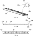
- FIG. 4a illustrates an isometric view of the tube 22 used in the Exhaust Gas Re-circulation (EGR) 100, also is illustrated an enlarged view of one end portion 22b of the tube 22 depicting the tab 22d configured thereon.
- FIG. 4b illustrates a side view of the tube 22, also is illustrated an enlarged view of one end portion 22b of the tube 22 depicting the tab 22d configured thereon.
- FIG. 4c illustrates a top view of the tube 22.
- the first and second end portions 22a, 22b of each of the heat exchanger tube 22 includes respective tabs 22c, 22d configured thereon, the tabs 22c, 22d are configured on at least one pair of opposite sides of section at the respective end portions 22a, 22b of the heat exchange tube 22.
- the tabs 22c, 22d fuse to form a part of welding joint between the end portions 22a, 22b of the heat exchanger tube 22 and the inside walls of corresponding slots 32a, 32b configured on the collector plates 30a, 30b. With such configuration of the tabs, 22c, 22d, sufficient fusion material is available at the weld site for configuring robust weld joint between the end portions 22a, 22b of the heat exchanger tube 22 and the inside walls of corresponding slots 32a, 32b.
- FIG. 2 illustrates sectional view of a first side of the EGR cooler 100 depicting internal details. Also, is illustrated an enlarged view of first end portion 22a of a heat exchanger tube of the plurality of heat exchanger tubes 22 before welding, along with the tabs 22c formed on lateral sides of rectangular section at the first end portion 22a of the heat exchanger tube 22.
- the rectangular sections at the first end portions 22a of the tubes 22 are complimentary to and are received in the slots 32a configured on the corresponding collector plates 30a.
- the tabs 22c are configured on opposite sides of a rectangular section at the first end portion 22a of the heat exchanger tubes 22.
- the tabs 22c are extending axially outward from the first end portion 22a of the heat exchanger tube 22.
- the heat exchanger tube 22 along with the tabs 22c configured at the first end portion 22a of the heat exchanger tube 22 and tabs 22d configured at the second end portion 22b of the tube 22 is configured by stamping, bending and welding operation. More specifically, a blank is so stamped and folded along fold lines that tabs 22c, 22d are configured at respective end portions 22a, 22b of the tube 22 when stamped blank is folded along fold lines and joined along the join line 22e illustrated in FIG. 4b .
- the end portion 22a of the heat exchanger tube 22 further includes a protrusion 22f (that acts as a poka-yoke feature for ensuring insertion of the end portion 22a of the tube 22 in predetermined position and orientation with respect to the slot 32a configured on the collector plate 30a such that at least a portion of the tabs 22c extending out of the slot 32a, fuse and form a part of the weld joint during welding to configure secure weld joint between the end portion 22a of the heat exchanger tube 22 and inside walls of the slot 32a configured on the collector plate 30a.
- a protrusion 22f that acts as a poka-yoke feature for ensuring insertion of the end portion 22a of the tube 22 in predetermined position and orientation with respect to the slot 32a configured on the collector plate 30a such that at least a portion of the tabs 22c extending out of the slot 32a, fuse and form a part of the weld joint during welding to configure secure weld joint between the end portion 22a of the heat exchanger tube 22 and
- At least one of the end portions 22a, 22b includes protrusion 22f, 22g that acts as poka-yoke feature for ensuring insertion of a predetermined length of the end portion 22a, 22b of the tube 22 in the slots 32a, 32b configured on the collector plates 30a, 30b respectively.
- the tabs 22c provide additional material that fuse during the welding to provide sufficient fusion material at the welding site and configure part of the welding joint to facilitate configuring robust joint between the first end portion 22a of the tube 22 and inside walls of the corresponding slot 32a configured on the first collector plate 30a of the EGR cooler 100.
- the tabs 22c are formed on lateral sides of rectangular section at the first end portion 22a of the tube 22, however, the present invention is not limited to any particular configuration, number and placement of the tabs 22c, method of configuring the tabs 22c on the tubes as far as the tabs 22c fuse during the welding of the first end portion 22a of the tube 22 to the inside walls of the slot 32a configured on the collector plate 30a to provide sufficient fusion material at the welding site to facilitate configuring robust joint between the first end portion 22a of the heat exchanger tube 22 and inside walls of the corresponding slot 32a configured on the first collector plate 30a of the EGR cooler 100.
- FIG. 3 illustrates a sectional view of a second side of the EGR cooler 100 depicting internal details. Also, is illustrated an enlarged view of the second end portion 22b of a heat exchanger tube of the plurality of heat exchanger tubes 22 before welding, along with the tabs 22d formed on lateral sides of rectangular section at the second end portion 22b of the tube 22.
- the rectangular sections at the second end portions 22b of the tubes 22 are complimentary to and are received in the slots 32b configured on the corresponding collector plates 30b.
- the tabs 22d are configured on opposite sides of a rectangular section at the second end portion 22b of the heat exchanger tubes 22.
- the tabs 22d are extending axially outward from the second end portion 22b of the heat exchanger tube 22.
- the heat exchanger tube 22 along with the tabs 22d configured at the second end portion 22b of the heat exchanger tube 22 and the tabs 22c configured at the first end portion 22a of the heat exchanger tube 22 is configured by stamping, bending and welding operation. More specifically, a blank is so stamped and folded along fold lines that tabs 22c, 22d are configured at respective end portions 22a, 22b of the tube 22 when the stamped blank is folded along fold lines and joined along the join line 22e illustrated in FIG. 4b .
- the end portion 22b of the tube 22 further includes a protrusion 22g as illustrated in FIG.
- the tabs 22d provide additional material that fuse during the welding to provide sufficient fusion material at the welding site and configure part of the welding joint to facilitate configuring robust joint between the second end portion 22b of the tube 22 and inside walls of a corresponding slot 32b configured on the second collector plate 30b of the EGR cooler 100.
- the tabs 22d are formed on lateral sides of rectangular section at the second end portion 22b of the tube 22, however, the present invention is not limited to any particular configuration, number and placement of the tabs 22d, method of configuring the tabs 22d on the tubes 22 as far as the tabs 22d fuse during the welding of the second end portion 22b of the tube 22 to the inside walls of the corresponding slot 32b to provide sufficient fusion material at the welding site to facilitate configuring robust joint between the second end portion 22b of the tube 22 and inside walls of the corresponding slot 32b configured on the second collector plate 30b of the EGR cooler 100.
- FIG. 5 illustrates a block diagram depicting the steps involved in assembling a heat exchanger in accordance with an embodiment of the present invention.
- the method includes the steps of closing one end of housing 10 with a first collector plate 30a. Thereafter, receiving a plurality of heat exchanger tubes 22 of a heat exchanger core 20 within the housing 10 such that first end portion 22a of the heat exchanger tubes 22 are received in the slots 32a configured on the first collector plate 30a.
Description
- The present invention relates to a heat exchanger, particularly, an Exhaust Gas Re-circulation (EGR) cooler, heat exchanger tubes configuring joint between the heat exchanger tubes and inside walls configuring slots on respective collector plates of the EGR cooler, and a method for assembling an EGR cooler. An EGR cooler according to the preamble of claim 1 is disclosed in
EP 1 306 640 . - A conventional heat exchanger, such as for example, an Exhaust Gas Re-circulation (EGR) cooler includes housing, a pair of spaced apart collector plates disposed at ends of the housing, a heat exchanger core received inside the housing, wherein end portions of heat exchanger tubes of the heat exchanger core are received in slots configured on the respective collector plates. The heat exchanger further includes a pair of heat exchanger tanks, hereinafter, referred to as tanks, wherein each tank is joined to the corresponding collector plate for configuring a sealed connection there between. The tanks are capable of receiving first heat exchanging fluid, often pressurized heat exchanging fluid such as exhaust gases. The tanks in conjunction with the corresponding collector plates facilitate distribution of first heat exchange fluid, particularly, exhaust gases to and collection of first heat exchange fluid from the heat exchange core respectively. The tanks are further connected to respective flanges. The housing receives second heat exchange media, particularly coolant therein and around the heat exchanger tubes through at least one inlet. The second heat exchange media or coolant is delivered out of the housing through at least one outlet after the coolant had extracted heat from the first heat exchange fluid, particularly, exhaust gases flowing through the heat exchanger tubes.
- Generally, end portions of the heat exchanger tubes are received inside slots configured on respective collector plates. The end portions of the heat exchanger tubes are joined to inside walls of the slots configured on the collector plates by welding, particularly, laser welding. However, the joint between the end portions of the heat exchanger tubes and the inside walls of the slots configured on the collector plates is prone to welding defects, particularly, lack of welding due to in-sufficient fusion material at the welding site due to the movement of the molten material (plasma) and difficulty in maintaining the molten material at the welding site. Due to lack of welding, gaps appear between the end portions of the heat exchanger tubes and inside walls of the respective slots configured on the collector plates.
- Such welding defects are common in case the thickness of the tubes is less and the welding is high speed welding. The welding defects such as gaps between the end portions of the heat exchanger tubes and inside walls of the respective slots may cause leakage and adversely impact the efficiency and performance of the heat exchanger. The welding defects can be prevented by regulating the process parameters, such as for example, laser energy, pulse duration, pulse frequency, power and welding speed during the welding process, however, regulating the process parameters during the welding is complicated and in-convenient. The heat exchangers manufactured by conventional welding processes fails to address the issue of welding defects arising due to insufficient fusion material during high speed welding of the end portions of thin heat exchanger tubes to inside walls of slots.
- Accordingly, there is a need for a heat exchanger with such configuration of heat exchanger tubes that even through thin, enables welding, particularly, high speed welding of end portions of the heat exchanger tubes to inside walls of slots configured on collector plates, without causing any welding defects and without need for regulating process parameters during welding. Further, there is a need for a heat exchanger with such configuration of heat exchanger tubes that provide sufficient fusion material to achieve robust welding joint between end portions of thin heat exchanger tubes and inside walls of slots configured on collector plates of a heat exchanger.
- An object of the present invention is to obviate the drawbacks associated with conventional heat exchanger configured with the conventional heat exchanger tubes.
- Another object of the present invention is to provide a heat exchanger with such configuration of heat exchanger tubes that provide sufficient fusion material for configuring robust weld joint between end portions of the heat exchanger tubes and inside walls of slots configured on the corresponding collector plates.
- Another object of the present invention is to provide a simple process for eliminating welding defects caused during high speed welding of end portions of thin heat exchanger tubes to inside walls of slots configured on the collector plate.
- In the present description, some elements or parameters may be indexed, such as a first element and a second element. In this case, unless stated otherwise, this indexation is only meant to differentiate and name elements which are similar but not identical. No idea of priority should be inferred from such indexation, as these terms may be switched without betraying the invention. Additionally, this indexation does not imply any order in mounting or use of the elements of the invention.
- A heat exchanger is disclosed in accordance with an embodiment of the present invention. The heat exchanger includes housing, a heat exchanger core, a pair of collector plates, a pair of tanks. The heat exchanger core includes a plurality of heat exchanger tubes. The pair of collector plates is disposed at end portions of the heat exchanger tubes. The pair of collector plates is configured with slots that receive the respective end portions of the heat exchanger tubes. The pair of tanks is connected to the respective collector plates. The end portions of each of the plurality of heat exchanger tubes include respective tabs configured thereon. The tabs are configured on at least one pair of opposite sides of section at the respective end portions of the heat exchanger tube and fuse to form a part of welding joint between the end portions of the heat exchange tube and inside walls of the corresponding slots on the collector plates.
- Generally, the tabs are extending axially outward from the respective end portions of the plurality of heat exchange tubes.
- Specifically, the tabs are configured on opposite sides of rectangular section at the end portions of the plurality of heat exchange tubes.
- In accordance with an embodiment of the present invention, the heat exchanger tubes along with the tabs configured at the end portions of the heat exchanger tubes are configured by stamping, bending and welding operation.
- Particularly, the tabs configured at the end portions of the heat exchanger tubes fuse to provide sufficient fusion material for configuring robust weld joint between end portions of the heat exchanger tubes and the inside walls of the respective slots.
- Further, at least one of the end portions of each of the heat exchanger tubes includes a protrusion to ensure insertion of the end portions in predetermined position and configuration with respect to the slots such that during welding of the end portions of the heat exchanger tube to the inside walls of the slots, at least a portion of the tabs extending out of the slots, fuse and form a part of the weld joint to configure secure weld joint between the end portions of the heat exchange tube and inside walls of the slots configured on the respective collector plates.
- Further, heat exchanger includes a plurality of fins lodged between adjacent heat exchanger tubes.
- A method of assembling a heat exchanger is disclosed in accordance with an embodiment of the present invention. The method includes the steps of closing one end of housing with a first collector plate, thereafter, receiving a plurality of heat exchanger tubes of a heat exchanger core within the housing such that first end portion of the heat exchanger tubes are received in slots and at least a portion of tabs formed on the first end portion are extending out of the slots configured on the first collector plate, closing the opposite end of the housing with another collector plate such that second end portion of the heat exchanger tubes opposite to the first end portions are received in slots and at least a portion of tabs formed on the second end portion are extending out of the slots configured on the another collector plate disposed opposite to and spaced away from the first collector plate. Thereafter, welding the first and second end portions of the heat exchanger tubes to inside walls of the slots configured on the first and second collector plates respectively, wherein, during welding of the first and second end portions to the inside walls of the respective slots, tabs configured at the first and second end portions of the heat exchanger tubes respectively fuse to form part of welding joint between the first and second end portions of the heat exchange tube and inside walls of the corresponding slots.
- Other characteristics, details and advantages of the invention can be inferred from the description of the invention hereunder. A more complete appreciation of the invention and many of the attendant advantages thereof will be readily obtained as the same becomes better understood by reference to the following detailed description when considered in connection with the accompanying figures, wherein:
-
FIG. 1 illustrates an isometric view of a heat exchanger, particularly, an Exhaust Gas Re-circulation (EGR) cooler in accordance with an embodiment of the present invention; -
FIG. 2 illustrates a sectional view of a first side of the Exhaust Gas Re-circulation (EGR) cooler ofFIG. 1 depicting internal details, also, is illustrated an enlarged view of a first end portion of a tube before welding along with the tabs formed thereon; and -
FIG. 3 illustrates a sectional view of a second side of the Exhaust Gas Re-circulation (EGR) ofFIG. 1 depicting internal details, also, is illustrated an enlarged view of a second end portion of the tube opposite to the first end portion of the tube before welding, along with the tabs formed thereon; and -
FIG. 4a illustrates an isometric view of a heat exchanger tube in accordance with an embodiment of the present invention that is used in the Exhaust Gas Re-circulation (EGR) ofFIG. 1 , also is illustrated an enlarged view of one end of the heat exchanger tube depicting a tab out of a pair of tabs configured thereon; -
FIG. 4b illustrates a side view of the heat exchanger tube ofFIG. 4a , also is illustrated an enlarged view of one end portion of the heat exchanger tube depicting a tab out of a pair of tabs configured thereon; -
FIG. 4c illustrates a top view of the heat exchanger tube ofFIG. 4b ; and -
FIG. 5 illustrates a block diagram depicting the steps involved in assembling a heat exchanger in accordance with an embodiment of the present invention. - It must be noted that the figures disclose the invention in a detailed enough way to be implemented, said figures helping to better define the invention if needs be. The invention should however not be limited to the embodiment disclosed in the description.
- The present invention discloses a heat exchanger, particularly, an Exhaust Gas Re-circulation (EGR) cooler for vehicular applications, wherein the heat exchanger includes thin heat exchanger tubes configured to enable welding, particularly, high speed welding thereof with inside walls of slots configured on respective collector plates. Specifically, the configuration of the heat exchanger tubes facilitates high speed welding of thin heat exchanger tubes without causing any welding defects and without need for regulating process parameters during welding that is required during welding of conventional heat exchanger tubes. More specifically, the heat exchanger includes heat exchanger tubes of the present invention are configured to provide sufficient fusion material for forming robust weld joint between end portions of the heat exchanger tubes and inside walls of slots configured on corresponding collector plates, thereby preventing the any welding defects due to lack of fusion material at the weld site. However, the present invention is not limited to heat exchangers or EGR coolers only, and the present invention is applicable for any structure used in vehicular or non-vehicular applications that involves high speed welding of the tubular elements of thin sections, wherein the tubular elements are required to form robust weld joint with another elements.
- Referring to
FIG. 1 of the accompanying drawings, an isometric view of a heat exchanger, particularly, an Exhaust Gas Re-circulation (EGR) cooler 100, hereinafter referred to as EGR cooler 100 in accordance with an embodiment of the present invention is depicted.FIG. 2 andFIG. 3 illustrate sectional view of a first side and a second side of the Exhaust Gas Re-circulation (EGR) cooler 100 respectively. TheEGR cooler 100 includeshousing 10, aheat exchanger core 20, a pair of spaced apartcollector plates heat exchanger tanks flanges inlet 60a and anoutlet 60b. The pair ofcollector plates second collector plates heat exchanger core 20 respectively. Theheat exchanger core 20 is configured of a plurality of heat exchange elements, particularly,heat exchanger tubes 22 and a plurality offin elements 24 lodged between the adjacentheat exchanger tubes 22. The pair ofcollector plates slots respective end portions second end portions heat exchanger tubes 22. Theend portions heat exchanger tubes 22 having thin section are joined to inside walls of theslots respective collector plates collector plates heat exchanger core 20. Such configuration facilitates distribution of first heat exchange fluid, particularly, exhaust gases to be cooled, to and collection of first heat exchange fluid from theheat exchange core 20 respectively. Thehousing 10 receives second heat exchange media, particularly coolant therein and around theheat exchanger tubes 22 through at least oneinlet 60a. The second heat exchange media or coolant is delivered out of thehousing 10 through the at least oneoutlet 60b after the coolant had extracted heat from the first heat exchange fluid, particularly, the exhaust gases flowing through theheat exchanger tubes 22. Theheat exchanger core 20 is received inside thehousing 10 such that theheat exchanger tubes 22 in conjunction with thehousing 10 configure adjacent yet separated spaces between thecollector plates heat exchanger tubes 22 and second heat exchange fluid flowing outside theheat exchanger tubes 22. Each tank of the pair ofheat exchanger tanks corresponding collector plates collector plates corresponding tanks tanks tanks corresponding collector plates heat exchange core 20 respectively. Thetanks respective flanges -
FIG. 4a illustrates an isometric view of thetube 22 used in the Exhaust Gas Re-circulation (EGR) 100, also is illustrated an enlarged view of oneend portion 22b of thetube 22 depicting thetab 22d configured thereon.FIG. 4b illustrates a side view of thetube 22, also is illustrated an enlarged view of oneend portion 22b of thetube 22 depicting thetab 22d configured thereon.FIG. 4c illustrates a top view of thetube 22. The first andsecond end portions heat exchanger tube 22 includesrespective tabs tabs respective end portions heat exchange tube 22. Thetabs end portions heat exchanger tube 22 and the inside walls of correspondingslots collector plates end portions heat exchanger tube 22 and the inside walls of correspondingslots - Again referring to
FIG. 2 of the accompanying FIGS., wherein theFIG. 2 illustrates sectional view of a first side of the EGR cooler 100 depicting internal details. Also, is illustrated an enlarged view offirst end portion 22a of a heat exchanger tube of the plurality ofheat exchanger tubes 22 before welding, along with thetabs 22c formed on lateral sides of rectangular section at thefirst end portion 22a of theheat exchanger tube 22. The rectangular sections at thefirst end portions 22a of thetubes 22 are complimentary to and are received in theslots 32a configured on thecorresponding collector plates 30a. Thetabs 22c are configured on opposite sides of a rectangular section at thefirst end portion 22a of theheat exchanger tubes 22. Thetabs 22c are extending axially outward from thefirst end portion 22a of theheat exchanger tube 22. Theheat exchanger tube 22 along with thetabs 22c configured at thefirst end portion 22a of theheat exchanger tube 22 andtabs 22d configured at thesecond end portion 22b of thetube 22 is configured by stamping, bending and welding operation. More specifically, a blank is so stamped and folded along fold lines thattabs respective end portions tube 22 when stamped blank is folded along fold lines and joined along thejoin line 22e illustrated inFIG. 4b . Theend portion 22a of theheat exchanger tube 22 further includes aprotrusion 22f (that acts as a poka-yoke feature for ensuring insertion of theend portion 22a of thetube 22 in predetermined position and orientation with respect to theslot 32a configured on thecollector plate 30a such that at least a portion of thetabs 22c extending out of theslot 32a, fuse and form a part of the weld joint during welding to configure secure weld joint between theend portion 22a of theheat exchanger tube 22 and inside walls of theslot 32a configured on thecollector plate 30a. In a preferred embodiment, at least one of theend portions protrusion end portion tube 22 in theslots collector plates tabs 22c provide additional material that fuse during the welding to provide sufficient fusion material at the welding site and configure part of the welding joint to facilitate configuring robust joint between thefirst end portion 22a of thetube 22 and inside walls of thecorresponding slot 32a configured on thefirst collector plate 30a of theEGR cooler 100. Although, thetabs 22c are formed on lateral sides of rectangular section at thefirst end portion 22a of thetube 22, however, the present invention is not limited to any particular configuration, number and placement of thetabs 22c, method of configuring thetabs 22c on the tubes as far as thetabs 22c fuse during the welding of thefirst end portion 22a of thetube 22 to the inside walls of theslot 32a configured on thecollector plate 30a to provide sufficient fusion material at the welding site to facilitate configuring robust joint between thefirst end portion 22a of theheat exchanger tube 22 and inside walls of thecorresponding slot 32a configured on thefirst collector plate 30a of theEGR cooler 100. - Similarly again referring to
FIG. 3 of the accompanying FIGS., theFIG 3 illustrates a sectional view of a second side of the EGR cooler 100 depicting internal details. Also, is illustrated an enlarged view of thesecond end portion 22b of a heat exchanger tube of the plurality ofheat exchanger tubes 22 before welding, along with thetabs 22d formed on lateral sides of rectangular section at thesecond end portion 22b of thetube 22. The rectangular sections at thesecond end portions 22b of thetubes 22 are complimentary to and are received in theslots 32b configured on thecorresponding collector plates 30b. Thetabs 22d are configured on opposite sides of a rectangular section at thesecond end portion 22b of theheat exchanger tubes 22. Thetabs 22d are extending axially outward from thesecond end portion 22b of theheat exchanger tube 22. Theheat exchanger tube 22 along with thetabs 22d configured at thesecond end portion 22b of theheat exchanger tube 22 and thetabs 22c configured at thefirst end portion 22a of theheat exchanger tube 22 is configured by stamping, bending and welding operation. More specifically, a blank is so stamped and folded along fold lines thattabs respective end portions tube 22 when the stamped blank is folded along fold lines and joined along thejoin line 22e illustrated inFIG. 4b . Theend portion 22b of thetube 22 further includes aprotrusion 22g as illustrated inFIG. 4a that acts as a poka-yoke feature for ensuring insertion of a pre-determined length of theend portion 22b of thetube 22 in correct position and orientation with respect to theslot 32b configured on thecollector plate 30b. Such configuration enables thetabs 22d to form a part of the weld joint during welding of theend portions 22b of theheat exchanger tubes 22 to the inside walls configuring theslot 32b configured on thecollector plate 30b, thereby configuring secure weld joint between theend portion 22b of thetube 22 and inside walls of theslot 32b configured on thecollector plate 30b. Thetabs 22d provide additional material that fuse during the welding to provide sufficient fusion material at the welding site and configure part of the welding joint to facilitate configuring robust joint between thesecond end portion 22b of thetube 22 and inside walls of acorresponding slot 32b configured on thesecond collector plate 30b of theEGR cooler 100. Although, thetabs 22d are formed on lateral sides of rectangular section at thesecond end portion 22b of thetube 22, however, the present invention is not limited to any particular configuration, number and placement of thetabs 22d, method of configuring thetabs 22d on thetubes 22 as far as thetabs 22d fuse during the welding of thesecond end portion 22b of thetube 22 to the inside walls of thecorresponding slot 32b to provide sufficient fusion material at the welding site to facilitate configuring robust joint between thesecond end portion 22b of thetube 22 and inside walls of thecorresponding slot 32b configured on thesecond collector plate 30b of theEGR cooler 100. - Also, a method of assembling a heat exchanger, particularly, an EGR cooler 100 is disclosed in accordance with an embodiment of the present invention.
FIG. 5 illustrates a block diagram depicting the steps involved in assembling a heat exchanger in accordance with an embodiment of the present invention. The method includes the steps of closing one end ofhousing 10 with afirst collector plate 30a. Thereafter, receiving a plurality ofheat exchanger tubes 22 of aheat exchanger core 20 within thehousing 10 such thatfirst end portion 22a of theheat exchanger tubes 22 are received in theslots 32a configured on thefirst collector plate 30a. Thereafter, closing the opposite end of thehousing 10 with anothercollector plate 30b such that thesecond end portion 22b of theheat exchanger tubes 22 opposite to thefirst end portion 22a are received inslots 32b configured on the anothercollector plate 30b disposed opposite to and spaced away from thefirst collector plate 30a. Thereafter, welding the first andsecond end portions heat exchanger tubes 22 to inside walls ofslots second end portions slots second collector plates tabs second end portions heat exchanger tubes 22 respectively fuse to form part of the welding joint between the first andsecond end portions heat exchange tube 22 and inside walls of thecorresponding slots
Claims (8)
- A heat exchanger (100) comprising:• housing (10);• a heat exchanger core (20) comprising a plurality of heat exchanger tubes (22);• a pair of collector plates (30a, 30b) disposed at end portions (22a, 22b) of the heat exchanger tubes (22), the pair of collector plates (30a, 30b) is configured with slots (32a, 32b) respectively adapted to receive respective end portions (22a, 22b) of the heat exchanger tubes (22); and• a pair of tanks (40a, 40b) connected to the respective collector plates (30a, 30b),characterized in that the end portions (22a, 22b) of each of the plurality of heat exchanger tubes (22) comprises respective tabs (22c, 22d) configured thereon, the tabs (22c, 22d) are configured on at least one pair of opposite sides of section at the respective end portions (22a, 22b) of the heat exchange tube (22) and are adapted to fuse to form a part of welding joint between the end portions (22a,22b) of the heat exchange tube (22) and inside walls of the corresponding slots (32a,32b) on the collector plates (30a, 30b).
- The heat exchanger (100) as claimed in the previous claim, wherein the tabs (22c, 22d) are extending axially outward from the respective end portions (22a, 22b) of the plurality of heat exchange tubes (22).
- The heat exchanger (100) as claimed in claim 1, wherein the tabs (22c, 22d) are configured on opposite sides of rectangular section at the respective end portions (22a, 22b) of the plurality of heat exchange tubes (22).
- The heat exchanger (100) as claimed in claim 1, wherein the heat exchanger tubes (22) along with the tabs (22c,22d) configured at the respective end portions (22a, 22b) of the heat exchanger tubes (22) are configured by stamping, bending and welding operation.
- The heat exchanger (100) as claimed in claim 1, wherein the tabs (22c, 22d) configured at the respective end portions (22a, 22b) of the heat exchanger tubes (22) are adapted to fuse to provide sufficient fusion material for configuring robust weld joint between the end portions (22a, 22b) of the heat exchanger tubes (22) and the inside walls of the respective slots (32a, 32b).
- The heat exchanger (100) as claimed in claim 1, wherein at least one of the end portions (22a, 22b) of each of the heat exchanger tubes (22) comprises a protrusion (22f, 22g) adapted to ensure insertion of the end portions (22a, 22b) in predetermined position and configuration with respect to the slots (32a, 32b) such that during welding of the end portions (22a, 22b) of the heat exchanger tube (22) to the inside walls of the slots (32a, 32b), at least a portion of the tabs (22c, 22d) extending out of the slots, fuse and form a part of the weld joint to configure secure weld joint between the end portions (22a, 22b) of the heat exchange tube (22) and inside walls of the slots (32a,32b) configured on the respective collector plates (30a, 30b).
- The heat exchanger (100) as claimed in claim 1, further comprising a plurality of fins (24) lodged between adjacent heat exchanger tubes (22).
- A method of assembling a heat exchanger (100), the method comprising the steps of:• closing one end of a housing (10) with a first collector plate (30a);• receiving a plurality of heat exchanger tubes (22) of a heat exchanger core (20) within the housing (10) such that first end portion (22a) of the heat exchanger tubes (22) are received in slots (32a) and at least a portion of tabs (22c) formed on the first end portion (22a) are extending out of the slots (32a) configured on the first collector plate (30a);• closing the opposite end of the housing (10) with another collector plate (30b) such that second end portion (22b) of the heat exchanger tubes (22) opposite to the first end portion (22a) are received in slots (30b) and at least a portion of tabs (22d) formed on the second end portion (22b) are extending out of the slots (32b) configured on the another collector plate (30b) disposed opposite to and spaced away from the first collector plate (30a);• welding the first and second end portions (22a, 22b) of the heat exchanger tubes (22) to inside walls of the slots (32a, 32b) configured on the first and second collector plates (30a, 30b) respectively,characterized in that, during welding of the first and second end portions (22a, 22b) to the inside walls of the respective slots (32a,32b), the tabs (22c, 22d) configured at the first and second end portions (22a, 22b) of the heat exchanger tubes (22) respectively fuse to form part of welding joint between the first and second end portions (22a, 22b) of the heat exchange tube (22) and inside walls of the corresponding slots (32a, 32b).
Priority Applications (1)
| Application Number | Priority Date | Filing Date | Title |
|---|---|---|---|
| EP19382415.8A EP3742099B1 (en) | 2019-05-23 | 2019-05-23 | A heat exchanger |
Applications Claiming Priority (1)
| Application Number | Priority Date | Filing Date | Title |
|---|---|---|---|
| EP19382415.8A EP3742099B1 (en) | 2019-05-23 | 2019-05-23 | A heat exchanger |
Publications (2)
| Publication Number | Publication Date |
|---|---|
| EP3742099A1 EP3742099A1 (en) | 2020-11-25 |
| EP3742099B1 true EP3742099B1 (en) | 2021-11-03 |
Family
ID=66685541
Family Applications (1)
| Application Number | Title | Priority Date | Filing Date |
|---|---|---|---|
| EP19382415.8A Active EP3742099B1 (en) | 2019-05-23 | 2019-05-23 | A heat exchanger |
Country Status (1)
| Country | Link |
|---|---|
| EP (1) | EP3742099B1 (en) |
Family Cites Families (5)
| Publication number | Priority date | Publication date | Assignee | Title |
|---|---|---|---|---|
| US3972371A (en) * | 1972-04-26 | 1976-08-03 | Societe Anonyme Des Usines Chausson | Tube and tube-plate assembly |
| US5366006A (en) * | 1993-03-01 | 1994-11-22 | Mccord Heat Transfer Corporation | Tab joint between coolant tube and header |
| DE10156611A1 (en) * | 2001-10-26 | 2003-05-08 | Behr Gmbh & Co | Tube bottom for exhaust gas heat exchanger |
| JP4182413B2 (en) * | 2003-03-27 | 2008-11-19 | 株式会社ティラド | Heat exchanger |
| EP1559983B1 (en) * | 2004-01-28 | 2007-08-22 | Madioen Holding B.V. | Method for forming a welded connection between a tubesheet and a number of tubes and a device produced by such method |
-
2019
- 2019-05-23 EP EP19382415.8A patent/EP3742099B1/en active Active
Also Published As
| Publication number | Publication date |
|---|---|
| EP3742099A1 (en) | 2020-11-25 |
Similar Documents
| Publication | Publication Date | Title |
|---|---|---|
| US8002022B2 (en) | Heat exchanger, in particular exhaust gas heat exchanger for motor vehicles | |
| EP1978323B1 (en) | Heat exchanger with telescopic expansion joint | |
| EP0450619B1 (en) | Heat exchanger tank partition device | |
| US20050121179A1 (en) | Exhaust gas heat exchanger | |
| US20070000652A1 (en) | Heat exchanger with dimpled tube surfaces | |
| KR20050036796A (en) | Brazing method | |
| JP2001174169A (en) | Heat exchanger | |
| WO2007064494A1 (en) | Heat exchanger with modified tube surface feature | |
| JP2002137054A (en) | Heat exchanger and its production method | |
| EP3742099B1 (en) | A heat exchanger | |
| JP2018128183A (en) | Heat exchanger | |
| KR100336712B1 (en) | Plate-fin type heat exchanger and method for manufacturing the same | |
| US9067289B2 (en) | Heat exchanger with telescoping expansion joint | |
| EP3722724B1 (en) | Fluid-tight joint for heat exchanger and heat exchanger comprising such a joint. | |
| EP2405224B1 (en) | Process for manufacturing a brazed heat exchanger | |
| JP4493221B2 (en) | Manufacturing method of stacked heat exchanger | |
| US11340027B2 (en) | Tube for a heat exchanger, and method of making the same | |
| EP3741985A1 (en) | An exhaust gas re-circulation (egr) cooler | |
| EP4310431A1 (en) | Thermal control device, especially for cooling an electrical component | |
| JP2005076926A (en) | Heat exchanger and manufacturing method of the same | |
| CN110520685B (en) | Heat exchanger for gases, in particular exhaust gases from an engine, gas circulation tube for an exchanger and method for manufacturing an exchanger | |
| EP4339542A1 (en) | A reinforcing insert for a heat exchanger tube | |
| US20220288729A1 (en) | Manufacturing process for heat exchangers | |
| JP2005315514A (en) | Method of manufacturing radiator with built-in oil cooler and oil cooler | |
| JP2022122062A (en) | Heat exchanger |
Legal Events
| Date | Code | Title | Description |
|---|---|---|---|
| PUAI | Public reference made under article 153(3) epc to a published international application that has entered the european phase |
Free format text: ORIGINAL CODE: 0009012 |
|
| STAA | Information on the status of an ep patent application or granted ep patent |
Free format text: STATUS: THE APPLICATION HAS BEEN PUBLISHED |
|
| AK | Designated contracting states |
Kind code of ref document: A1 Designated state(s): AL AT BE BG CH CY CZ DE DK EE ES FI FR GB GR HR HU IE IS IT LI LT LU LV MC MK MT NL NO PL PT RO RS SE SI SK SM TR |
|
| AX | Request for extension of the european patent |
Extension state: BA ME |
|
| STAA | Information on the status of an ep patent application or granted ep patent |
Free format text: STATUS: REQUEST FOR EXAMINATION WAS MADE |
|
| 17P | Request for examination filed |
Effective date: 20210409 |
|
| GRAP | Despatch of communication of intention to grant a patent |
Free format text: ORIGINAL CODE: EPIDOSNIGR1 |
|
| RBV | Designated contracting states (corrected) |
Designated state(s): AL AT BE BG CH CY CZ DE DK EE ES FI FR GB GR HR HU IE IS IT LI LT LU LV MC MK MT NL NO PL PT RO RS SE SI SK SM TR |
|
| STAA | Information on the status of an ep patent application or granted ep patent |
Free format text: STATUS: GRANT OF PATENT IS INTENDED |
|
| RIC1 | Information provided on ipc code assigned before grant |
Ipc: F28D 7/16 20060101AFI20210430BHEP Ipc: B21D 53/02 20060101ALI20210430BHEP Ipc: B23K 33/00 20060101ALI20210430BHEP Ipc: B23P 15/26 20060101ALI20210430BHEP Ipc: F02M 26/22 20160101ALI20210430BHEP Ipc: F28D 21/00 20060101ALI20210430BHEP Ipc: F28F 1/02 20060101ALI20210430BHEP Ipc: F28F 1/42 20060101ALI20210430BHEP Ipc: F28F 9/18 20060101ALI20210430BHEP |
|
| INTG | Intention to grant announced |
Effective date: 20210520 |
|
| GRAS | Grant fee paid |
Free format text: ORIGINAL CODE: EPIDOSNIGR3 |
|
| GRAA | (expected) grant |
Free format text: ORIGINAL CODE: 0009210 |
|
| STAA | Information on the status of an ep patent application or granted ep patent |
Free format text: STATUS: THE PATENT HAS BEEN GRANTED |
|
| AK | Designated contracting states |
Kind code of ref document: B1 Designated state(s): AL AT BE BG CH CY CZ DE DK EE ES FI FR GB GR HR HU IE IS IT LI LT LU LV MC MK MT NL NO PL PT RO RS SE SI SK SM TR |
|
| REG | Reference to a national code |
Ref country code: GB Ref legal event code: FG4D |
|
| REG | Reference to a national code |
Ref country code: AT Ref legal event code: REF Ref document number: 1444323 Country of ref document: AT Kind code of ref document: T Effective date: 20211115 Ref country code: CH Ref legal event code: EP |
|
| REG | Reference to a national code |
Ref country code: IE Ref legal event code: FG4D |
|
| REG | Reference to a national code |
Ref country code: DE Ref legal event code: R096 Ref document number: 602019008964 Country of ref document: DE |
|
| REG | Reference to a national code |
Ref country code: LT Ref legal event code: MG9D |
|
| REG | Reference to a national code |
Ref country code: NL Ref legal event code: MP Effective date: 20211103 |
|
| REG | Reference to a national code |
Ref country code: AT Ref legal event code: MK05 Ref document number: 1444323 Country of ref document: AT Kind code of ref document: T Effective date: 20211103 |
|
| PG25 | Lapsed in a contracting state [announced via postgrant information from national office to epo] |
Ref country code: RS Free format text: LAPSE BECAUSE OF FAILURE TO SUBMIT A TRANSLATION OF THE DESCRIPTION OR TO PAY THE FEE WITHIN THE PRESCRIBED TIME-LIMIT Effective date: 20211103 Ref country code: LT Free format text: LAPSE BECAUSE OF FAILURE TO SUBMIT A TRANSLATION OF THE DESCRIPTION OR TO PAY THE FEE WITHIN THE PRESCRIBED TIME-LIMIT Effective date: 20211103 Ref country code: FI Free format text: LAPSE BECAUSE OF FAILURE TO SUBMIT A TRANSLATION OF THE DESCRIPTION OR TO PAY THE FEE WITHIN THE PRESCRIBED TIME-LIMIT Effective date: 20211103 Ref country code: BG Free format text: LAPSE BECAUSE OF FAILURE TO SUBMIT A TRANSLATION OF THE DESCRIPTION OR TO PAY THE FEE WITHIN THE PRESCRIBED TIME-LIMIT Effective date: 20220203 Ref country code: AT Free format text: LAPSE BECAUSE OF FAILURE TO SUBMIT A TRANSLATION OF THE DESCRIPTION OR TO PAY THE FEE WITHIN THE PRESCRIBED TIME-LIMIT Effective date: 20211103 |
|
| PG25 | Lapsed in a contracting state [announced via postgrant information from national office to epo] |
Ref country code: IS Free format text: LAPSE BECAUSE OF FAILURE TO SUBMIT A TRANSLATION OF THE DESCRIPTION OR TO PAY THE FEE WITHIN THE PRESCRIBED TIME-LIMIT Effective date: 20220303 Ref country code: SE Free format text: LAPSE BECAUSE OF FAILURE TO SUBMIT A TRANSLATION OF THE DESCRIPTION OR TO PAY THE FEE WITHIN THE PRESCRIBED TIME-LIMIT Effective date: 20211103 Ref country code: PT Free format text: LAPSE BECAUSE OF FAILURE TO SUBMIT A TRANSLATION OF THE DESCRIPTION OR TO PAY THE FEE WITHIN THE PRESCRIBED TIME-LIMIT Effective date: 20220303 Ref country code: PL Free format text: LAPSE BECAUSE OF FAILURE TO SUBMIT A TRANSLATION OF THE DESCRIPTION OR TO PAY THE FEE WITHIN THE PRESCRIBED TIME-LIMIT Effective date: 20211103 Ref country code: NO Free format text: LAPSE BECAUSE OF FAILURE TO SUBMIT A TRANSLATION OF THE DESCRIPTION OR TO PAY THE FEE WITHIN THE PRESCRIBED TIME-LIMIT Effective date: 20220203 Ref country code: NL Free format text: LAPSE BECAUSE OF FAILURE TO SUBMIT A TRANSLATION OF THE DESCRIPTION OR TO PAY THE FEE WITHIN THE PRESCRIBED TIME-LIMIT Effective date: 20211103 Ref country code: LV Free format text: LAPSE BECAUSE OF FAILURE TO SUBMIT A TRANSLATION OF THE DESCRIPTION OR TO PAY THE FEE WITHIN THE PRESCRIBED TIME-LIMIT Effective date: 20211103 Ref country code: HR Free format text: LAPSE BECAUSE OF FAILURE TO SUBMIT A TRANSLATION OF THE DESCRIPTION OR TO PAY THE FEE WITHIN THE PRESCRIBED TIME-LIMIT Effective date: 20211103 Ref country code: GR Free format text: LAPSE BECAUSE OF FAILURE TO SUBMIT A TRANSLATION OF THE DESCRIPTION OR TO PAY THE FEE WITHIN THE PRESCRIBED TIME-LIMIT Effective date: 20220204 Ref country code: ES Free format text: LAPSE BECAUSE OF FAILURE TO SUBMIT A TRANSLATION OF THE DESCRIPTION OR TO PAY THE FEE WITHIN THE PRESCRIBED TIME-LIMIT Effective date: 20211103 |
|
| PG25 | Lapsed in a contracting state [announced via postgrant information from national office to epo] |
Ref country code: SM Free format text: LAPSE BECAUSE OF FAILURE TO SUBMIT A TRANSLATION OF THE DESCRIPTION OR TO PAY THE FEE WITHIN THE PRESCRIBED TIME-LIMIT Effective date: 20211103 Ref country code: SK Free format text: LAPSE BECAUSE OF FAILURE TO SUBMIT A TRANSLATION OF THE DESCRIPTION OR TO PAY THE FEE WITHIN THE PRESCRIBED TIME-LIMIT Effective date: 20211103 Ref country code: RO Free format text: LAPSE BECAUSE OF FAILURE TO SUBMIT A TRANSLATION OF THE DESCRIPTION OR TO PAY THE FEE WITHIN THE PRESCRIBED TIME-LIMIT Effective date: 20211103 Ref country code: EE Free format text: LAPSE BECAUSE OF FAILURE TO SUBMIT A TRANSLATION OF THE DESCRIPTION OR TO PAY THE FEE WITHIN THE PRESCRIBED TIME-LIMIT Effective date: 20211103 Ref country code: DK Free format text: LAPSE BECAUSE OF FAILURE TO SUBMIT A TRANSLATION OF THE DESCRIPTION OR TO PAY THE FEE WITHIN THE PRESCRIBED TIME-LIMIT Effective date: 20211103 Ref country code: CZ Free format text: LAPSE BECAUSE OF FAILURE TO SUBMIT A TRANSLATION OF THE DESCRIPTION OR TO PAY THE FEE WITHIN THE PRESCRIBED TIME-LIMIT Effective date: 20211103 |
|
| REG | Reference to a national code |
Ref country code: DE Ref legal event code: R097 Ref document number: 602019008964 Country of ref document: DE |
|
| PLBE | No opposition filed within time limit |
Free format text: ORIGINAL CODE: 0009261 |
|
| STAA | Information on the status of an ep patent application or granted ep patent |
Free format text: STATUS: NO OPPOSITION FILED WITHIN TIME LIMIT |
|
| 26N | No opposition filed |
Effective date: 20220804 |
|
| PG25 | Lapsed in a contracting state [announced via postgrant information from national office to epo] |
Ref country code: AL Free format text: LAPSE BECAUSE OF FAILURE TO SUBMIT A TRANSLATION OF THE DESCRIPTION OR TO PAY THE FEE WITHIN THE PRESCRIBED TIME-LIMIT Effective date: 20211103 |
|
| PG25 | Lapsed in a contracting state [announced via postgrant information from national office to epo] |
Ref country code: SI Free format text: LAPSE BECAUSE OF FAILURE TO SUBMIT A TRANSLATION OF THE DESCRIPTION OR TO PAY THE FEE WITHIN THE PRESCRIBED TIME-LIMIT Effective date: 20211103 |
|
| REG | Reference to a national code |
Ref country code: CH Ref legal event code: PL |
|
| REG | Reference to a national code |
Ref country code: BE Ref legal event code: MM Effective date: 20220531 |
|
| PG25 | Lapsed in a contracting state [announced via postgrant information from national office to epo] |
Ref country code: MC Free format text: LAPSE BECAUSE OF FAILURE TO SUBMIT A TRANSLATION OF THE DESCRIPTION OR TO PAY THE FEE WITHIN THE PRESCRIBED TIME-LIMIT Effective date: 20211103 Ref country code: LU Free format text: LAPSE BECAUSE OF NON-PAYMENT OF DUE FEES Effective date: 20220523 Ref country code: LI Free format text: LAPSE BECAUSE OF NON-PAYMENT OF DUE FEES Effective date: 20220531 Ref country code: CH Free format text: LAPSE BECAUSE OF NON-PAYMENT OF DUE FEES Effective date: 20220531 |
|
| PG25 | Lapsed in a contracting state [announced via postgrant information from national office to epo] |
Ref country code: IE Free format text: LAPSE BECAUSE OF NON-PAYMENT OF DUE FEES Effective date: 20220523 |
|
| PG25 | Lapsed in a contracting state [announced via postgrant information from national office to epo] |
Ref country code: IT Free format text: LAPSE BECAUSE OF FAILURE TO SUBMIT A TRANSLATION OF THE DESCRIPTION OR TO PAY THE FEE WITHIN THE PRESCRIBED TIME-LIMIT Effective date: 20211103 Ref country code: BE Free format text: LAPSE BECAUSE OF NON-PAYMENT OF DUE FEES Effective date: 20220531 |
|
| P01 | Opt-out of the competence of the unified patent court (upc) registered |
Effective date: 20230603 |
|
| PGFP | Annual fee paid to national office [announced via postgrant information from national office to epo] |
Ref country code: FR Payment date: 20230523 Year of fee payment: 5 Ref country code: DE Payment date: 20230510 Year of fee payment: 5 |
|
| GBPC | Gb: european patent ceased through non-payment of renewal fee |
Effective date: 20230523 |