EP3044488B1 - Valve housing with a spindle guide and method for production thereof - Google Patents
Valve housing with a spindle guide and method for production thereof Download PDFInfo
- Publication number
- EP3044488B1 EP3044488B1 EP14842751.1A EP14842751A EP3044488B1 EP 3044488 B1 EP3044488 B1 EP 3044488B1 EP 14842751 A EP14842751 A EP 14842751A EP 3044488 B1 EP3044488 B1 EP 3044488B1
- Authority
- EP
- European Patent Office
- Prior art keywords
- valve
- spindle
- spindle guide
- guide stub
- tubular workpiece
- Prior art date
- Legal status (The legal status is an assumption and is not a legal conclusion. Google has not performed a legal analysis and makes no representation as to the accuracy of the status listed.)
- Not-in-force
Links
Images


Classifications
-
- F—MECHANICAL ENGINEERING; LIGHTING; HEATING; WEAPONS; BLASTING
- F16—ENGINEERING ELEMENTS AND UNITS; GENERAL MEASURES FOR PRODUCING AND MAINTAINING EFFECTIVE FUNCTIONING OF MACHINES OR INSTALLATIONS; THERMAL INSULATION IN GENERAL
- F16L—PIPES; JOINTS OR FITTINGS FOR PIPES; SUPPORTS FOR PIPES, CABLES OR PROTECTIVE TUBING; MEANS FOR THERMAL INSULATION IN GENERAL
- F16L55/00—Devices or appurtenances for use in, or in connection with, pipes or pipe systems
- F16L55/10—Means for stopping flow from or in pipes or hoses
- F16L55/105—Closing devices introduced radially into the pipe or hose
-
- F—MECHANICAL ENGINEERING; LIGHTING; HEATING; WEAPONS; BLASTING
- F16—ENGINEERING ELEMENTS AND UNITS; GENERAL MEASURES FOR PRODUCING AND MAINTAINING EFFECTIVE FUNCTIONING OF MACHINES OR INSTALLATIONS; THERMAL INSULATION IN GENERAL
- F16K—VALVES; TAPS; COCKS; ACTUATING-FLOATS; DEVICES FOR VENTING OR AERATING
- F16K27/00—Construction of housing; Use of materials therefor
- F16K27/02—Construction of housing; Use of materials therefor of lift valves
-
- F—MECHANICAL ENGINEERING; LIGHTING; HEATING; WEAPONS; BLASTING
- F16—ENGINEERING ELEMENTS AND UNITS; GENERAL MEASURES FOR PRODUCING AND MAINTAINING EFFECTIVE FUNCTIONING OF MACHINES OR INSTALLATIONS; THERMAL INSULATION IN GENERAL
- F16K—VALVES; TAPS; COCKS; ACTUATING-FLOATS; DEVICES FOR VENTING OR AERATING
- F16K27/00—Construction of housing; Use of materials therefor
- F16K27/06—Construction of housing; Use of materials therefor of taps or cocks
- F16K27/067—Construction of housing; Use of materials therefor of taps or cocks with spherical plugs
-
- F—MECHANICAL ENGINEERING; LIGHTING; HEATING; WEAPONS; BLASTING
- F16—ENGINEERING ELEMENTS AND UNITS; GENERAL MEASURES FOR PRODUCING AND MAINTAINING EFFECTIVE FUNCTIONING OF MACHINES OR INSTALLATIONS; THERMAL INSULATION IN GENERAL
- F16K—VALVES; TAPS; COCKS; ACTUATING-FLOATS; DEVICES FOR VENTING OR AERATING
- F16K27/00—Construction of housing; Use of materials therefor
- F16K27/08—Guiding yokes for spindles; Means for closing housings; Dust caps, e.g. for tyre valves
-
- F—MECHANICAL ENGINEERING; LIGHTING; HEATING; WEAPONS; BLASTING
- F16—ENGINEERING ELEMENTS AND UNITS; GENERAL MEASURES FOR PRODUCING AND MAINTAINING EFFECTIVE FUNCTIONING OF MACHINES OR INSTALLATIONS; THERMAL INSULATION IN GENERAL
- F16K—VALVES; TAPS; COCKS; ACTUATING-FLOATS; DEVICES FOR VENTING OR AERATING
- F16K27/00—Construction of housing; Use of materials therefor
- F16K27/10—Welded housings
- F16K27/107—Welded housings for taps or cocks
Definitions
- the present invention concerns a method for making a valve for regulating a fluid, the valve including a valve housing with a central part and with one, two or more connection ends, the connection ends extending away from the central part, wherein internally of the central part there is arranged a valve body, for example with a through-going opening, the valve body arranged in a valve seat and connected to a valve spindle, the valve spindle arranged in a spindle guide stub on the valve housing.
- the invention furthermore concerns a valve for regulating a fluid, the valve including a valve housing with a central part and with one, two or more connection ends, the connection ends extending away from the central part, wherein internally of the central part there is arranged a valve body, for example with a through-going opening, the valve body arranged in a valve seat and connected to a valve spindle, the valve spindle arranged in a spindle guide stub on the valve housing and that the valve housing is made from a tubular workpiece.
- valves e.g. ball valves
- valve housings of several parts and then assemble these parts around a valve seat and a valve body.
- Such valves are typically made of brass or other cupper-based alloy and are typically assembled by corresponding screw threads in respective parts, or alternatively by means of bolts.
- the spindle guide stub will typically be mounted with a threaded joint or by a welding on the valve housing itself.
- valve body When speaking of a ball valve, the valve body is, as indicated by the name, spherical and with an outer size which is greater than the connecting openings in the valve housing.
- a valve therefore has a valve housing with an internal geometry in which valve seat and valve body are disposed.
- the valve housing is typically joined in the vicinity of the valve body as the latter requires the largest internal dimension.
- Such valves are typically made of cast workpieces which are formed and shaped by machining into the desired geometry. This shaping process is, however, rather cost-intensive for several reasons.
- the individual workpieces are to be cast and then handled and machined one by one in a suitable metal cutting unit. Since the workpieces are individually machined, the process is time-consuming, irrespective of the application of modern and rapid processes.
- JP H04-32369 A discloses a method for making a valve for regulating a fluid, the valve including a valve housing.
- the central part of the valve housing comprises a valve body arranged in the central part.
- the valve body is arranged in a valve seat and connected to a valve spindle.
- the valve spindle is arranged in a spindle guide stub on the valve housing, and the spindle guide stub has a collar along its lower edge (when looked upside down) and a cutout in the upper surface (when looked upside down) of the spindle guide stub.
- DE 3503030 A1 discloses a valve that comprises a valve housing with a central part and with two or more connection ends, the connection ends extending away from the central part, and where internally of the central part there is arranged a valve body arranged in a valve seat and connected to a valve spindle.
- the valve spindle is arranged in a spindle guide stub on the valve housing, which is made of a tubular workpiece and includes a spindle guide stub, the spindle guide stub being welded on the tubular workpiece in a traditional way.
- valves for heating and cooling systems for potable water and for other purposes in steel, e.g. carbon steel or stainless steel which is cheaper and which can be worked with modern production equipment directly from a plate piece or a tube piece faster and cheaper than possible when casting and machining workpieces of brass.
- steel e.g. carbon steel or stainless steel which is cheaper and which can be worked with modern production equipment directly from a plate piece or a tube piece faster and cheaper than possible when casting and machining workpieces of brass.
- crevice corrosion can arise in cavities between two surfaces in a joint, e.g. in threaded joints, which may cause a substantially shortened service life of the valves so that they have to be removed from the system due to the crevice corrosion. Therefore it is also greatly desired to avoid such joints between the valve parts where there is a risk that crevice corrosion will occur.
- a valve housing can be made of a tubular workpiece, wherein a minimum number of chip removing and cutting processes are performed before mounting a valve seat and a valve body, and therefore is cheaper and which can be worked directly from a plate workpiece or a tubular workpiece with modern production equipment.
- valve housing prior to the mounting itself of valve seat and valve body is preferably performed before final shaping of the valve housing itself.
- this is achieved by a method of making a valve at least including that a plate-shaped workpiece is provided, that a plastic deformation of the plate-shaped workpiece in the form of a collaring on the plate-shaped workpiece is performed whereby a spindle guide stub is formed, as the spindle guide stub has a collar along its lower edge and a cutout at the upper end which has an edge face with a shape such that the edge face on the spindle guide stub forms an opening with arresting faces at the outer end of the spindle guide stub.
- the collar has a saddle shape, and the method further comprising the steps of providing a tubular workpiece with a cutout in the tubular workpiece; and welding the spindle guide stub on the tubular workpiece by a welding running around the cutout in the tubular item such that there is provided an internal welding seam running along the edge of the inner opening in the collar of the spindle guide stub and along the cutout and at the outer side of the tubular workpiece.
- the object of the invention is thus also achieved by a valve with the valve housing made from a tubular workpiece.
- the valve is special in that it includes a plastically deformed, collared spindle guide stub with a collar along its lower end and an opening at its upper end, as the spindle guide stub is welded on tubular workpiece by a welding, such as a welding around the cutout in the tubular workpiece such that there is provided an internal welding seam running along the edge of the inner opening in the collar of the spindle guide stub and along the cutout and at the outer side of the tubular workpiece.
- the collar has a saddle shape and the spindle guide stub is welded on the tubular workpiece by a welding, such as a conventional welding or a laser welding, around a cutout in the tubular workpiece such that there is provided an internal welding seam running along the edge of the inner opening in the collar of the spindle guide stub and along the cutout and at the outer side of the tubular workpiece.
- a welding such as a conventional welding or a laser welding
- the plate-shaped workpiece is plane prior to shaping and is provided a saddle-shape simultaneously with the forming of the spindle guide stub by collaring.
- the blank holder and the draw ring in the deep drawing tool are provided with a groove and a bead, respectively, with a shape as a part of a cylinder so that the plane workpiece, the metal disc, becomes saddle-shaped with a curved shape at the bottom side of the collar of the spindle guide stub corresponding to the curvature at the outer side of the tubular workpiece.
- the shaping of the spindle guide stub is thereby performed with the lowest possible costs.
- the plate-shaped workpiece can have saddle-shape before the shaping operation.
- the method according to the invention includes that there is provided a tubular workpiece with a cutout in the tubular workpiece, and that the collared spindle guide stub is welded on the tubular workpiece.
- Welding is e.g. a conventional welding or preferably a laser welding around the cutout in the tubular item.
- an internal welding seam running along the edge of the inner opening in the collar of the spindle guide stub and along the cutout and at the outer side of the tubular workpiece.
- the welding seam will cover the gap arising between the spindle guide stub collar and the outer side face of the valve housing itself. It is thereby avoided that fluid, most often a liquid or a gas, can penetrate into the gap and contribute to crevice corrosion.
- this way of mounting the spindle guide stub on the valve housing is rapid, and it is easy to automate the welding process, e.g. by robots, such that it is made uniformly and accurately on all valves.
- this possibility of automating the mounting of the spindle guide stub will result in significantly lower production costs per valve unit.
- this welding seam can be laid particularly accurately at the gap between the stub collar and the outer side face of the valve housing, thereby reducing uncertainties in the position of the welding seam, and thereby further reducing the risk of crevice corrosion.
- a method for producing a valve according to the invention can include that the tubular workpiece is provided by deep drawing or a corresponding process where e.g. a plate piece is worked by deformation into having a more or less tubular shape.
- a method for producing a valve according to the invention can be so that the tubular item is provided by shortening a prefabricated tube piece with the desired dimensions.
- valve housing which is only constituted by a single item formed in one piece without any kind of joining by welding, bolting or similar joining methods.
- a method for producing a valve according to the invention can include that the valve spindle is mounted in the spindle guide stub before welding thereof on the tubular workpiece.
- a collar is formed on the spindle guide stub, contributing to keeping to the valve spindle in position in the valve spindle stub, and that the valve spindle is retained thereby in the spindle guide stub without use of a stopper or similar which is normally fastened to the spindle guide stub with a screw thread. This will provide that cutting a screw thread in the spindle guide stub is avoided, meaning that the costs of making the valve are further reduced.
- the spindle guide stub When the spindle guide stub is mounted in the spindle guide stub while using one or more packings, the spindle is kept in position at the same time during the subsequent method steps. Furthermore, the packings ensure that the valve is dry in the spindle stub afterwards, and finally the risk of the spindle dropping out during the subsequent mounting steps is reduced.
- the opening at the upper end of the spindle guide stub includes one or more arresting faces that limit rotation of the spindle in the spindle guide stub.
- the valve housing further includes one or more collared stubs, which are preferably suited for mounting one or more sensors, and/or which can be connected to equipment for leak testing the valve.
- a sensor can e.g. be a temperature sensor, a pressure sensor or another kind of sensor.
- valve body and valve seats are placed in the valve housing before the final shaping of the ends of the tubular workpiece for forming the ends of the valve housing, since it is thereby possible to form the valve housing with ends with reduced diameter relative to the central part where valve seat and valve bodies are disposed.
- a valve including a valve housing according to the invention is typically designed such that the connection ends have an inner diameter which substantially corresponds to the inner diameter of the valve body. This is therefore a so-called fullflow valve which advantageously can be used in many places where there is a need for a more unhindered flow in the medium flowing through the valve.
- the connection ends on the valve housing can be designed according to need and can be with male ends as well as female ends and include all thinkable types of couplings for connecting pipes or hoses, including couplings of the press-fit type.
- thinwalled materials gain a foothold in the industry and are increasingly applied to industrial solutions as well as to plumbing installations in residential buildings.
- There are innumerable advantages connected with thinwalled pipes and fittings and the jointing methods are very simple whereby time-consuming and cost-raising work of threading, welding or soldering is avoided.
- a valve housing according to the invention can advantageously be made of a thinwalled material, such as untreated or surface treated carbon steel or stainless steel, where the valve housing and/or the spindle guide stub are/is formed by plastic deformation of the material, e.g. by hydraulic shaping or by axial shaping or by another suitable process.
- Particularly hydraulic shaping and axial shaping have appeared to be very well suited for making a valve housing as such processes are rapid and cheap compared with traditional production methods for valve housings, which are typically made of sintered, cast or forged brass or other suitable material which is machined afterwards and fitted with a valve insert.
- hydraulic shaping and axial shaping are very accurate shaping methods and good tolerances can be attained.
- the ends of the valve housing are shaped under heating, e.g.
- valve housing where valve body, valve seat and possible packings are disposed are kept cool during the shaping procedure such that the internal parts of the valve such as packings, valve body and seats are not damaged by the thermal action during the heating of the ends of the valve housing, and possibly completed by an annealing of the ends of the valve housing, e.g. under a protecting atmosphere.
- the valve can be made of e.g. untreated steel in a series of contiguous and automated processes, and after mounting the production can be completed with a surface finishing.
- Such a valve and method for producing a valve is very advantageous as the process is simple, takes place in a straightforward sequence and is completed with finishing of the surface.
- valve housing may advantageously be made of e.g. stainless steel.
- surface treatment of the valve housing is no longer necessary, entailing a lower production cost of the finished product.
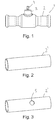
- Fig. 1 appears a valve 1 with a valve housing 1 where the valve housing 1 has a central part and two connection ends.
- the two connection ends are here shown with a design adapted as so-called pressfittings. However, this is irrelevant to the invention and only an example of how these connection ends can be made.
- a valve body e.g. with a through-going aperture in a valve seat.
- a valve spindle 4 extends up through a spindle guide stub 3. By turning this valve spindle 4 about its longitudinal axis, the valve body can be moved between an open position and a closed position.
- Fig. 2 shows a tubular workpiece 2' which is to be formed into a valve housing.
- a circular or substantially circular cutout 5 or a hole through the wall of the tubular workpiece 2' as shown on Fig. 3 .
- the tubular workpiece 2' is then ready for mounting a spindle guide stub 3 and a valve spindle 4 before mounting the valve body and seats (not shown) in the tubular workpiece 2'.
- the tubular workpiece 2' is, as mentioned in the introduction of the application, preferably provided by plastic deformation, such as by deep drawing, hydraulic shaping or axial shaping or a corresponding process where e.g. a plate piece is worked by deformation into having a more or less tubular shape.
- the tubular item 2' can be provided by shortening a prefabricated tube piece with the desired dimensions.
- the cutout 5 in the tubular workpiece 2' is cut in a conventional way, including e.g. by laser, ensuring that the cutout 5 is cut with very great precision.
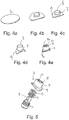
- the spindle guide stub 3 itself is formed by plastic deformation ( Figs. 4a-4e ) of a plate-shaped workpiece 6 ( Fig. 4a ) which is preferably cut in a circular or approximately circular shape.
- the spindle guide stub 3 is formed as shown in Figs. 4b-4e with a collar 7, an upper end face 8 and a collar 9 along its lower edge.
- the collar 7 preferably has cylindrical or approximately cylindrical shape.
- the lower collar 9 has saddle shape where radius of the curvature at the bottom side thereof corresponds to radius of the circular curvature at the outer side of the wall of the tubular workpiece 2'. The shape of the collar 9 is thereby adapted to the tubular workpiece 2' on which the spindle guide stub 3 is to be mounted.
- the plastic deformation of the plate-shaped workpiece 6 is preferably effected by deep drawing, hydraulic shaping or corresponding suitable conventional methods.
- This opening 10 includes preferably one or two projections 10a that constitute arresting faces for rotation of the valve spindle.
- the lower collar 9 of the valve spindle is optionally cut as possibly there may be formed one or more flanges 9a along the outer edge of the collar 9.
- valve spindle 4 is then mounted in the spindle stub 3 as shown in Fig. 5 .
- One or more packings 11 are disposed around the spindle 4, preferably in grooves 12 cut for the purpose in the valve spindle 4.
- one or more O-rings 13 can be used for positioning and/or retaining the valve spindle 4 in the spindle guide stub 3.
- the spindle guide stub 3 is fitted with the premounted valve spindle 4 on the tubular workpiece 2', as shown in Figs. 6-8 .
- the spindle guide stub is placed across the cutout 5 such that the valve spindle 4 projects into the tubular workpiece 2' through the cutout 5, most clearly seen in Fig. 7a showing the tube piece 2 with the mounted spindle guide stub 3 and valve spindle 4 in cross-section through the spindle guide stub.
- the spindle guide stub 3 is fastened to the tube piece 2' by laser welding such that the welding beam is directed towards the joint between tube piece 2' and collar 9 of the spindle guide stub 3 from outside the collar 9.
- a welding robot can be applied thereby, and the welding seam 14 can be laid with great precision.
- Fig. 7b shows a detail in cross-section of the joint between the collar of the spindle guide stub and the area around the cutout 5 of the tube piece 2'. It appears here that the welding seam 14 is disposed close to the cutout 5. This disposition of the welding seam 14 entail that the risk of crevice corrosion or pitting arising in the joint between the outer side of the tube piece 2' and the bottom side of the collar 9 is eliminated, or at least significantly reduced.
- the flanges 9a on the collar 9 of the spindle guide stub 3 may in an embodiment of the valve be used as stop for rotation of the valve spindle 4 as a handle, actuator or similar mounted on the valve spindle 4 on the finished valve can be designed such that it covers the spindle stub 3, whereby these flanges 9a on the collar 9 can function as stop for rotation of handle/actuator, and thereby also the valve spindle 4.
- This design entails that it becomes possible to put an external packing along the outer side of the spindle guide 4, sealing between spindle guide and handle/actuator, and thereby reducing the risk of leakage from the valve spindle compared with other valves where there are only internal packings between the inner surface of the spindle guide stub 4 and the valve spindle.
- valve body After mounting spindle guide stub 3 with the valve spindle 4 on the tubular workpiece 2', valve body, valve seats and possible packings are mounted in connection therewith as the valve spindle 4 in this connection is also fastened to the valve body. Then the valve housing itself is shaped for forming the finished valve, see Fig. 1 .
- the term “approximately” is used which includes the tolerances seen as normal by the skilled in the art.
- the term “approximately circular” is used, and “approximately” is here to be understood in the way that the skilled in the art visually perceives the shape as circular or substantially circular, besides including the tolerances seen as normal by the skilled in the art by possible measuring and determining the shape of the workpiece.
Description
- The present invention concerns a method for making a valve for regulating a fluid, the valve including a valve housing with a central part and with one, two or more connection ends, the connection ends extending away from the central part, wherein internally of the central part there is arranged a valve body, for example with a through-going opening, the valve body arranged in a valve seat and connected to a valve spindle, the valve spindle arranged in a spindle guide stub on the valve housing.
- The invention furthermore concerns a valve for regulating a fluid, the valve including a valve housing with a central part and with one, two or more connection ends, the connection ends extending away from the central part, wherein internally of the central part there is arranged a valve body, for example with a through-going opening, the valve body arranged in a valve seat and connected to a valve spindle, the valve spindle arranged in a spindle guide stub on the valve housing and that the valve housing is made from a tubular workpiece.
- It is commonly known to make valves, e.g. ball valves, and thereby valve housings of several parts and then assemble these parts around a valve seat and a valve body. Such valves are typically made of brass or other cupper-based alloy and are typically assembled by corresponding screw threads in respective parts, or alternatively by means of bolts. The spindle guide stub will typically be mounted with a threaded joint or by a welding on the valve housing itself.
- When speaking of a ball valve, the valve body is, as indicated by the name, spherical and with an outer size which is greater than the connecting openings in the valve housing. Such a valve therefore has a valve housing with an internal geometry in which valve seat and valve body are disposed. The valve housing is typically joined in the vicinity of the valve body as the latter requires the largest internal dimension. Such valves are typically made of cast workpieces which are formed and shaped by machining into the desired geometry. This shaping process is, however, rather cost-intensive for several reasons. The individual workpieces are to be cast and then handled and machined one by one in a suitable metal cutting unit. Since the workpieces are individually machined, the process is time-consuming, irrespective of the application of modern and rapid processes.
- In addition to the handling and machining of the cast workpieces prior to assembling around a valve seat and a valve body, the cost of the material also plays a significant role. Brass or other suitable alloys are expensive and imply an appreciably greater cost than e.g. common weldable carbon steel.
-
JP H04-32369 A -
DE 3503030 A1 discloses a valve that comprises a valve housing with a central part and with two or more connection ends, the connection ends extending away from the central part, and where internally of the central part there is arranged a valve body arranged in a valve seat and connected to a valve spindle. The valve spindle is arranged in a spindle guide stub on the valve housing, which is made of a tubular workpiece and includes a spindle guide stub, the spindle guide stub being welded on the tubular workpiece in a traditional way. - There is thus an expressed desire for making valves for heating and cooling systems, for potable water and for other purposes in steel, e.g. carbon steel or stainless steel which is cheaper and which can be worked with modern production equipment directly from a plate piece or a tube piece faster and cheaper than possible when casting and machining workpieces of brass.
- At the same time, it is greatly desired to perform as few welding processes as possible on a valve as such processes cause the work pieces to be set up at least one more time and as a welding process is to be performed, which of course raise the cost of the product.
- Finally, crevice corrosion can arise in cavities between two surfaces in a joint, e.g. in threaded joints, which may cause a substantially shortened service life of the valves so that they have to be removed from the system due to the crevice corrosion. Therefore it is also greatly desired to avoid such joints between the valve parts where there is a risk that crevice corrosion will occur.
- It is the object of the invention to indicate a solution to the above problem wherein a valve housing can be made of a tubular workpiece, wherein a minimum number of chip removing and cutting processes are performed before mounting a valve seat and a valve body, and therefore is cheaper and which can be worked directly from a plate workpiece or a tubular workpiece with modern production equipment.
- It is also an object that the making of the parts of the valve housing prior to the mounting itself of valve seat and valve body is preferably performed before final shaping of the valve housing itself.
- Finally, it is an object of the invention to provide a valve with a valve housing where the risk of crevice corrosion at the joint between the spindle guide stub and the valve housing can be avoided completely, or at least reduced considerably.
- According to the present invention, this is achieved by a method of making a valve at least including that a plate-shaped workpiece is provided, that a plastic deformation of the plate-shaped workpiece in the form of a collaring on the plate-shaped workpiece is performed whereby a spindle guide stub is formed, as the spindle guide stub has a collar along its lower edge and a cutout at the upper end which has an edge face with a shape such that the edge face on the spindle guide stub forms an opening with arresting faces at the outer end of the spindle guide stub. The collar has a saddle shape, and the method further comprising the steps of providing a tubular workpiece with a cutout in the tubular workpiece; and welding the spindle guide stub on the tubular workpiece by a welding running around the cutout in the tubular item such that there is provided an internal welding seam running along the edge of the inner opening in the collar of the spindle guide stub and along the cutout and at the outer side of the tubular workpiece.
- The object of the invention is thus also achieved by a valve with the valve housing made from a tubular workpiece. The valve is special in that it includes a plastically deformed, collared spindle guide stub with a collar along its lower end and an opening at its upper end, as the spindle guide stub is welded on tubular workpiece by a welding, such as a welding around the cutout in the tubular workpiece such that there is provided an internal welding seam running along the edge of the inner opening in the collar of the spindle guide stub and along the cutout and at the outer side of the tubular workpiece. Further the collar has a saddle shape and the spindle guide stub is welded on the tubular workpiece by a welding, such as a conventional welding or a laser welding, around a cutout in the tubular workpiece such that there is provided an internal welding seam running along the edge of the inner opening in the collar of the spindle guide stub and along the cutout and at the outer side of the tubular workpiece. In an embodiment of the method according to the invention, it is preferred that the plate-shaped workpiece is plane prior to shaping and is provided a saddle-shape simultaneously with the forming of the spindle guide stub by collaring. This can be done in a simple way in that the blank holder and the draw ring in the deep drawing tool are provided with a groove and a bead, respectively, with a shape as a part of a cylinder so that the plane workpiece, the metal disc, becomes saddle-shaped with a curved shape at the bottom side of the collar of the spindle guide stub corresponding to the curvature at the outer side of the tubular workpiece. The shaping of the spindle guide stub is thereby performed with the lowest possible costs. Alternatively, the plate-shaped workpiece can have saddle-shape before the shaping operation.
- As mentioned above, the method according to the invention includes that there is provided a tubular workpiece with a cutout in the tubular workpiece, and that the collared spindle guide stub is welded on the tubular workpiece. Welding is e.g. a conventional welding or preferably a laser welding around the cutout in the tubular item. By the welding is provided an internal welding seam running along the edge of the inner opening in the collar of the spindle guide stub and along the cutout and at the outer side of the tubular workpiece.
- By mounting the spindle guide stub such that the welding seam will run along the inner edge of opening between the spindle guide stub and at the outer side of the tubular workpiece and along the cutout therein, the welding seam will cover the gap arising between the spindle guide stub collar and the outer side face of the valve housing itself. It is thereby avoided that fluid, most often a liquid or a gas, can penetrate into the gap and contribute to crevice corrosion. At the same time, this way of mounting the spindle guide stub on the valve housing is rapid, and it is easy to automate the welding process, e.g. by robots, such that it is made uniformly and accurately on all valves. Moreover, this possibility of automating the mounting of the spindle guide stub will result in significantly lower production costs per valve unit. By using laser welding, this welding seam can be laid particularly accurately at the gap between the stub collar and the outer side face of the valve housing, thereby reducing uncertainties in the position of the welding seam, and thereby further reducing the risk of crevice corrosion.
- A method for producing a valve according to the invention can include that the tubular workpiece is provided by deep drawing or a corresponding process where e.g. a plate piece is worked by deformation into having a more or less tubular shape.
- Alternatively, a method for producing a valve according to the invention can be so that the tubular item is provided by shortening a prefabricated tube piece with the desired dimensions.
- Depending on material properties and the most advantageous production methods with regard to cost as well as with regard to tolerances or surface quality, there is a free choice between the said methods which each have their own specific advantages.
- Common to the said methods is that hereby can be produced a valve housing which is only constituted by a single item formed in one piece without any kind of joining by welding, bolting or similar joining methods.
- A method for producing a valve according to the invention can include that the valve spindle is mounted in the spindle guide stub before welding thereof on the tubular workpiece. Thereby is enabled that by the deep drawing a collar is formed on the spindle guide stub, contributing to keeping to the valve spindle in position in the valve spindle stub, and that the valve spindle is retained thereby in the spindle guide stub without use of a stopper or similar which is normally fastened to the spindle guide stub with a screw thread. This will provide that cutting a screw thread in the spindle guide stub is avoided, meaning that the costs of making the valve are further reduced.
- When the spindle guide stub is mounted in the spindle guide stub while using one or more packings, the spindle is kept in position at the same time during the subsequent method steps. Furthermore, the packings ensure that the valve is dry in the spindle stub afterwards, and finally the risk of the spindle dropping out during the subsequent mounting steps is reduced.
- In an embodiment of the valve, the opening at the upper end of the spindle guide stub includes one or more arresting faces that limit rotation of the spindle in the spindle guide stub. By designing the cutout, i.e. the opening, in the disc with e.g. the shown shape prior to deep drawing, these arresting or stop faces will automatically appear in the opening of the spindle guide stub during deep drawing of the spindle guide stub.
- In a further embodiment of the valve, the valve housing further includes one or more collared stubs, which are preferably suited for mounting one or more sensors, and/or which can be connected to equipment for leak testing the valve. Such a sensor can e.g. be a temperature sensor, a pressure sensor or another kind of sensor.
- By the method it is preferred that valve body and valve seats are placed in the valve housing before the final shaping of the ends of the tubular workpiece for forming the ends of the valve housing, since it is thereby possible to form the valve housing with ends with reduced diameter relative to the central part where valve seat and valve bodies are disposed.
- A valve including a valve housing according to the invention is typically designed such that the connection ends have an inner diameter which substantially corresponds to the inner diameter of the valve body. This is therefore a so-called fullflow valve which advantageously can be used in many places where there is a need for a more unhindered flow in the medium flowing through the valve. The connection ends on the valve housing can be designed according to need and can be with male ends as well as female ends and include all thinkable types of couplings for connecting pipes or hoses, including couplings of the press-fit type.
- At the time being, thinwalled materials gain a foothold in the industry and are increasingly applied to industrial solutions as well as to plumbing installations in residential buildings. There are innumerable advantages connected with thinwalled pipes and fittings and the jointing methods are very simple whereby time-consuming and cost-raising work of threading, welding or soldering is avoided.
- A valve housing according to the invention can advantageously be made of a thinwalled material, such as untreated or surface treated carbon steel or stainless steel, where the valve housing and/or the spindle guide stub are/is formed by plastic deformation of the material, e.g. by hydraulic shaping or by axial shaping or by another suitable process. Particularly hydraulic shaping and axial shaping have appeared to be very well suited for making a valve housing as such processes are rapid and cheap compared with traditional production methods for valve housings, which are typically made of sintered, cast or forged brass or other suitable material which is machined afterwards and fitted with a valve insert. Furthermore, hydraulic shaping and axial shaping are very accurate shaping methods and good tolerances can be attained. Alternatively, the ends of the valve housing are shaped under heating, e.g. by induction, as the central part of the valve housing where valve body, valve seat and possible packings are disposed are kept cool during the shaping procedure such that the internal parts of the valve such as packings, valve body and seats are not damaged by the thermal action during the heating of the ends of the valve housing, and possibly completed by an annealing of the ends of the valve housing, e.g. under a protecting atmosphere.
- By this method, the valve can be made of e.g. untreated steel in a series of contiguous and automated processes, and after mounting the production can be completed with a surface finishing. Such a valve and method for producing a valve is very advantageous as the process is simple, takes place in a straightforward sequence and is completed with finishing of the surface.
- In a preferred variant of the invention, the valve housing may advantageously be made of e.g. stainless steel. Hereby is achieved the obvious advantage that surface treatment of the valve housing is no longer necessary, entailing a lower production cost of the finished product.
- The invention will now be explained below with reference to the drawing, where:
- Fig. 1
- shows a valve according to the invention, seen from the side;
- Fig. 2
- shows a tubular workpiece which is further worked into a valve housing;
- Fig. 3
- shows the tubular workpiece with a cutout;
- Figs. 4a-4e
- show making of a spindle guide stub for the valve;
- Fig. 5
- shows mounting of a spindle in spindle guide stub;
- Fig. 6
- shows spindle guide stub with spindle and the tubular workpiece before;
- Fig. 7a
- shows a cross-section of the tubular workpiece with spindle guide stub welded thereon;
- Fig. 7b
- shows a detail of
Fig. 7a around the welding seam; and - Fig. 8
- shows the tubular workpiece with spindle guide stub welded thereon before shaping of the tubular workpiece into a finished valve housing.
- In the explanation of the Figures, identical or corresponding elements will be provided with the same designations in different Figures. Therefore, no explanation of all details will be given in connection with each single Figure/embodiment.
- In
Fig. 1 appears a valve 1 with a valve housing 1 where the valve housing 1 has a central part and two connection ends. The two connection ends are here shown with a design adapted as so-called pressfittings. However, this is irrelevant to the invention and only an example of how these connection ends can be made. In the central part is arranged a valve body, e.g. with a through-going aperture in a valve seat. From the valve body, which is preferably constituted by a traditional ball known from various ball valves, avalve spindle 4 extends up through aspindle guide stub 3. By turning thisvalve spindle 4 about its longitudinal axis, the valve body can be moved between an open position and a closed position. -
Fig. 2 shows a tubular workpiece 2' which is to be formed into a valve housing. In the tubular workpiece is formed a circular or substantiallycircular cutout 5, or a hole through the wall of the tubular workpiece 2' as shown onFig. 3 . The tubular workpiece 2' is then ready for mounting aspindle guide stub 3 and avalve spindle 4 before mounting the valve body and seats (not shown) in the tubular workpiece 2'. - The tubular workpiece 2' is, as mentioned in the introduction of the application, preferably provided by plastic deformation, such as by deep drawing, hydraulic shaping or axial shaping or a corresponding process where e.g. a plate piece is worked by deformation into having a more or less tubular shape. Alternatively, the tubular item 2' can be provided by shortening a prefabricated tube piece with the desired dimensions.
- The
cutout 5 in the tubular workpiece 2' is cut in a conventional way, including e.g. by laser, ensuring that thecutout 5 is cut with very great precision. - The
spindle guide stub 3 itself is formed by plastic deformation (Figs. 4a-4e ) of a plate-shaped workpiece 6 (Fig. 4a ) which is preferably cut in a circular or approximately circular shape. - The
spindle guide stub 3 is formed as shown inFigs. 4b-4e with acollar 7, anupper end face 8 and acollar 9 along its lower edge. Thecollar 7 preferably has cylindrical or approximately cylindrical shape. Thelower collar 9 has saddle shape where radius of the curvature at the bottom side thereof corresponds to radius of the circular curvature at the outer side of the wall of the tubular workpiece 2'. The shape of thecollar 9 is thereby adapted to the tubular workpiece 2' on which thespindle guide stub 3 is to be mounted. - The plastic deformation of the plate-shaped
workpiece 6 is preferably effected by deep drawing, hydraulic shaping or corresponding suitable conventional methods. - An opening 10 is then cut in the
end face 8 of the spindle guide stub, seeFig. 4e . - This opening 10 includes preferably one or two projections 10a that constitute arresting faces for rotation of the valve spindle.
- Then the
lower collar 9 of the valve spindle is optionally cut as possibly there may be formed one or more flanges 9a along the outer edge of thecollar 9. - The
valve spindle 4 is then mounted in thespindle stub 3 as shown inFig. 5 . One or more packings 11 are disposed around thespindle 4, preferably in grooves 12 cut for the purpose in thevalve spindle 4. In addition, one or more O-rings 13 can be used for positioning and/or retaining thevalve spindle 4 in thespindle guide stub 3. - After that, the
spindle guide stub 3 is fitted with thepremounted valve spindle 4 on the tubular workpiece 2', as shown inFigs. 6-8 . The spindle guide stub is placed across thecutout 5 such that thevalve spindle 4 projects into the tubular workpiece 2' through thecutout 5, most clearly seen inFig. 7a showing thetube piece 2 with the mountedspindle guide stub 3 andvalve spindle 4 in cross-section through the spindle guide stub. - The
spindle guide stub 3 is fastened to the tube piece 2' by laser welding such that the welding beam is directed towards the joint between tube piece 2' andcollar 9 of thespindle guide stub 3 from outside thecollar 9. A welding robot can be applied thereby, and thewelding seam 14 can be laid with great precision.Fig. 7b shows a detail in cross-section of the joint between the collar of the spindle guide stub and the area around thecutout 5 of the tube piece 2'. It appears here that thewelding seam 14 is disposed close to thecutout 5. This disposition of thewelding seam 14 entail that the risk of crevice corrosion or pitting arising in the joint between the outer side of the tube piece 2' and the bottom side of thecollar 9 is eliminated, or at least significantly reduced. - The flanges 9a on the
collar 9 of thespindle guide stub 3 may in an embodiment of the valve be used as stop for rotation of thevalve spindle 4 as a handle, actuator or similar mounted on thevalve spindle 4 on the finished valve can be designed such that it covers thespindle stub 3, whereby these flanges 9a on thecollar 9 can function as stop for rotation of handle/actuator, and thereby also thevalve spindle 4. This design entails that it becomes possible to put an external packing along the outer side of thespindle guide 4, sealing between spindle guide and handle/actuator, and thereby reducing the risk of leakage from the valve spindle compared with other valves where there are only internal packings between the inner surface of thespindle guide stub 4 and the valve spindle. - After mounting
spindle guide stub 3 with thevalve spindle 4 on the tubular workpiece 2', valve body, valve seats and possible packings are mounted in connection therewith as thevalve spindle 4 in this connection is also fastened to the valve body. Then the valve housing itself is shaped for forming the finished valve, seeFig. 1 . - In the present application, the term "approximately" is used which includes the tolerances seen as normal by the skilled in the art. For example, the term "approximately circular" is used, and "approximately" is here to be understood in the way that the skilled in the art visually perceives the shape as circular or substantially circular, besides including the tolerances seen as normal by the skilled in the art by possible measuring and determining the shape of the workpiece.
- The invention is not limited to the above described embodiments and not to the embodiments shown in the drawings either, but may be supplemented and modified in any way according to the invention as specified and defined in the claims.
Claims (11)
- A method for making a valve for regulating a fluid, the valve including a valve housing (1) with a central part and with one, two or more connection ends, the connection ends extending away from the central part, wherein internally of the central part there is arranged a valve body, for example with a through-going opening, the valve body arranged in a valve seat and connected to a valve spindle (4), the valve spindle arranged in a spindle guide stub (3) on the valve housing, characterised in that the making of the spindle stub (3) at least includes the following steps:- providing a plate-shaped workpiece;- providing a plastic deformation of the plate-shaped workpiece in the form of a collar on the plate-shaped workpiece, whereby the spindle guide stub (3) is formed as the spindle guide stub has a collar (9) along its lower edge and a cutout (10) in the upper surface (8) of the spindle guide stub, wherein the collar (9) has a saddle shape, the method further comprising the steps of providing a tubular workpiece (2') with a cutout (5) in the tubular workpiece; and welding the spindle guide stub (3) on the tubular workpiece (2') by a welding running around the cutout (5) in the tubular workpiece (2') such that there is provided an internal welding seam (14) running along the edge of an inner opening in the collar (9) of the spindle guide stub (3) and along the cutout (5) and at the outer side of the tubular workpiece.
- Method for making a valve according to claim 1, characterised in that the plate-shaped workpiece is plane and is provided with the saddle-shape simultaneously with forming the spindle guide stub (3) by the collaring.
- Method for making a valve according to claim 1, characterised in that the welding is a laser welding.
- Method for making a valve according to any of claim 1-3, characterised in that the tubular workpiece (2') is provided by deep drawing or a corresponding process where e.g. a plate piece is worked by deformation into having a more or less tubular shape.
- Method for making a valve according to any of claims 1 to 4, characterised in that the tubular workpiece (2') is provided by shortening a prefabricated tube piece with the desired dimensions.
- Method for making a valve according to any of claims 1 to 5, characterised in that the valve spindle (4) is mounted in the spindle guide stub (3) before welding the latter on the tubular workpiece.
- Method for making a valve according to claim 1, characterised in that the valve spindle (4) is mounted in the spindle guide stub (3) while applying one or more packings.
- Method for making a valve according to any of claims 1 to 7, characterised in that the valve body and the valve seat are provided in the valve housing (1) before final shaping of the ends of the tubular workpiece (2') for forming of the ends of the valve housing.
- A valve for regulating a fluid, the valve including a valve housing (1) with a central part and with one, two or more connection ends, the connection ends extending away from the central part, wherein internally of the central part there is arranged a valve body, for example with a through-going opening, the valve body arranged in a valve seat and connected to a valve spindle (4), the valve spindle arranged in a spindle guide stub (3) on the valve housing, the valve housing (1) being made of a tubular workpiece (2'), characterized in that the valve includes a plastically deformed, collared spindle guide stub (3) with a collar (9) along its lower end and an opening (10) at its upper end (8), the collar (9) has a saddle shape and in that the spindle guide stub (3) is welded on the tubular workpiece (2') by a welding, such as a conventional welding or a laser welding, around a cutout (5) in the tubular workpiece (2') such that there is provided an internal welding seam (14) running along the edge of an inner opening in the collar (9) of the spindle guide stub (3) and along the cutout (5) and at the outer side of the tubular workpiece (2').
- Valve according to claim 9, characterised in that the opening (10) at the upper end of the spindle guide stub includes one or more arresting faces (10a) that limit rotation of the spindle.
- Valve according to claim 9 or 10, characterised in that the valve housing (1) further includes one or more collared stubs, preferably for mounting one or more sensors.
Applications Claiming Priority (2)
| Application Number | Priority Date | Filing Date | Title |
|---|---|---|---|
| DK201370502A DK177973B1 (en) | 2013-09-09 | 2013-09-09 | Method of manufacturing a valve housing with spindle and valve housing |
| PCT/DK2014/050275 WO2015032415A1 (en) | 2013-09-09 | 2014-09-08 | Valve housing with a spindle guide and method for production thereof |
Publications (3)
| Publication Number | Publication Date |
|---|---|
| EP3044488A1 EP3044488A1 (en) | 2016-07-20 |
| EP3044488A4 EP3044488A4 (en) | 2017-04-05 |
| EP3044488B1 true EP3044488B1 (en) | 2018-07-18 |
Family
ID=52446129
Family Applications (1)
| Application Number | Title | Priority Date | Filing Date |
|---|---|---|---|
| EP14842751.1A Not-in-force EP3044488B1 (en) | 2013-09-09 | 2014-09-08 | Valve housing with a spindle guide and method for production thereof |
Country Status (6)
| Country | Link |
|---|---|
| US (1) | US9933101B2 (en) |
| EP (1) | EP3044488B1 (en) |
| CN (1) | CN105705848A (en) |
| DK (1) | DK177973B1 (en) |
| RU (1) | RU2659944C2 (en) |
| WO (1) | WO2015032415A1 (en) |
Families Citing this family (2)
| Publication number | Priority date | Publication date | Assignee | Title |
|---|---|---|---|---|
| DE102016223444B3 (en) * | 2016-11-25 | 2018-05-24 | smk systeme metall kunststoff gmbh & co. kg | Optimized flap valve for an exhaust flap system and manufacturing method therefor |
| JP7082375B2 (en) * | 2019-07-18 | 2022-06-08 | 株式会社不二工機 | Flow switching valve |
Family Cites Families (29)
| Publication number | Priority date | Publication date | Assignee | Title |
|---|---|---|---|---|
| US548779A (en) * | 1895-10-29 | Irrigation-hydrant | ||
| US500941A (en) * | 1893-07-04 | Chusetts | ||
| US2228857A (en) * | 1941-01-14 | Draft regulator | ||
| US1872357A (en) | 1930-08-11 | 1932-08-16 | Smith Corp A O | Forged manway construction for pressure vessels |
| US1966403A (en) * | 1931-03-05 | 1934-07-10 | Nassau Products | Welding union |
| FR1296084A (en) * | 1961-05-05 | 1962-06-15 | Applic Vide Optique Mecanique | Ball valve |
| US3275292A (en) * | 1962-07-19 | 1966-09-27 | Grinnell Corp | Diaphragm valve body flange construction |
| US3490734A (en) * | 1966-02-14 | 1970-01-20 | Rockwell Mfg Co | Ball valves |
| DE2534663A1 (en) * | 1975-08-02 | 1977-02-10 | Ellinger Gottfried | Ball valve with plastic body - is reinforced with metal tube to withstand higher pressures than all plastic valve |
| US4545231A (en) | 1982-08-16 | 1985-10-08 | Grove Valve & Regulator Company | Method of manufacturing a weld neck flange |
| ATE27477T1 (en) * | 1983-04-19 | 1987-06-15 | Klinger Ag | FITTING THAT CAN BE INSTALLATED INTO A PIPE TRAIN. |
| DE3503030A1 (en) * | 1985-01-30 | 1986-07-31 | Josef 6200 Wiesbaden Nemetz | Ball-cock housing |
| US5104155A (en) | 1985-02-22 | 1992-04-14 | Promat Engineering Services Limited | Transition pieces |
| JPH0432369A (en) | 1990-05-29 | 1992-02-04 | Mitsubishi Electric Corp | Focus circuit |
| JP2540394Y2 (en) * | 1990-07-13 | 1997-07-02 | 高砂熱学工業 株式会社 | Rotary valve seal structure |
| RU2003905C1 (en) * | 1991-07-20 | 1993-11-30 | Владимир Борисович Шубин | Ball cock |
| JP3113180B2 (en) | 1995-08-16 | 2000-11-27 | 株式会社幸伸技研 | Valve element for ball valve and method of manufacturing valve element |
| PT101871A (en) | 1996-05-07 | 1997-12-31 | Valvulas Arco S A | Parallel-branch and -passage valve for gaseous fluid conduits |
| KR100265250B1 (en) | 1997-11-27 | 2001-01-15 | 박주광 | Valve and manufacturing method thereof |
| RU2136998C1 (en) * | 1997-12-02 | 1999-09-10 | Закрытое акционерное общество "ГИРАС" | Ball cock and method for its manufacture |
| DE19945960A1 (en) | 1998-10-20 | 2000-04-27 | Plasson Armaturen Gmbh | Plastic ball valve manufacture for use as e.g. gas stop valve, produces material bond between inner section and outer casing, by melt injection welding, precluding all possibility of through-leakage between these parts |
| DE10102593B4 (en) | 2000-10-20 | 2007-12-13 | Continental Teves Ag & Co. Ohg | Closure device and method for fastening a closure body in a housing |
| EP1323965A1 (en) * | 2001-12-21 | 2003-07-02 | Suunnittelutoimisto A.J.A. Oy | Ball valve and its manufacturing method |
| SE532056C2 (en) * | 2007-02-02 | 2009-10-13 | Millipore Ab | valve seal |
| FR2928436A1 (en) * | 2008-03-04 | 2009-09-11 | Snecma Sa | DERIVATION FLANGE, DERIVATION DEVICE COMPRISING A MAIN PIPE AND SAID DERIVATION FLANGE, AND METHOD OF WELDING CONNECTION OF SUCH DERIVATION FLANGE. |
| CN201982790U (en) | 2011-04-19 | 2011-09-21 | 浙江三花股份有限公司 | Ball valve |
| US8794264B2 (en) | 2011-05-31 | 2014-08-05 | GM Global Technologies Operations LLC | Fluid valve port optimized for robustness with standard O-ring seal |
| CN104769344B (en) | 2012-08-13 | 2016-09-07 | 丹麦波昂公司 | There is the valve chest of axle ring type spindle guide |
| DK177971B1 (en) * | 2013-06-20 | 2015-02-09 | Broen As | Spring gasket for valve housing |
-
2013
- 2013-09-09 DK DK201370502A patent/DK177973B1/en not_active IP Right Cessation
-
2014
- 2014-09-08 EP EP14842751.1A patent/EP3044488B1/en not_active Not-in-force
- 2014-09-08 US US14/917,359 patent/US9933101B2/en not_active Expired - Fee Related
- 2014-09-08 RU RU2016111365A patent/RU2659944C2/en not_active IP Right Cessation
- 2014-09-08 CN CN201480048791.3A patent/CN105705848A/en active Pending
- 2014-09-08 WO PCT/DK2014/050275 patent/WO2015032415A1/en active Application Filing
Also Published As
| Publication number | Publication date |
|---|---|
| WO2015032415A1 (en) | 2015-03-12 |
| US9933101B2 (en) | 2018-04-03 |
| RU2016111365A (en) | 2017-10-12 |
| RU2016111365A3 (en) | 2018-05-10 |
| EP3044488A4 (en) | 2017-04-05 |
| DK177973B1 (en) | 2015-02-09 |
| CN105705848A (en) | 2016-06-22 |
| EP3044488A1 (en) | 2016-07-20 |
| US20160215915A1 (en) | 2016-07-28 |
| RU2659944C2 (en) | 2018-07-04 |
Similar Documents
| Publication | Publication Date | Title |
|---|---|---|
| US10850451B2 (en) | Fluid system and method of manufacture via friction welding | |
| US5941266A (en) | Angle entry rotary valve | |
| US20170175905A1 (en) | Fluid-handling components and methods of manufacture | |
| WO2014202096A1 (en) | Valve and method for making a valve | |
| US4450613A (en) | Method of manufacturing acute angled vessel connector | |
| US20220266388A1 (en) | A method for making a ball valve for regulating a fluid, a ball valve and a welding tool for holding and handling valve parts | |
| EP3044488B1 (en) | Valve housing with a spindle guide and method for production thereof | |
| US9777860B2 (en) | Valve housing with collared spindle guide | |
| EP3011208B1 (en) | Spring gasket for a valve housing | |
| CN112045375A (en) | Manufacturing process of environment-friendly valve body and product thereof | |
| JP6816872B2 (en) | Gate valve structure and its manufacturing method | |
| EP1969267B1 (en) | Fluid valve bodies and improved methods of manufacture | |
| JP7024956B2 (en) | Branch joints, branch construction methods, and branch joint manufacturing methods | |
| KR100603707B1 (en) | Molding apparatus of nozzle sleeve for chemistry fluid tank | |
| CN108223875B (en) | Fluid housing | |
| CA3155071A1 (en) | Method for producing a pipeline arrangement and pipeline arrangement | |
| US20160222481A1 (en) | System and method for annealing of an item, which comprises heat-sensitive parts and annealed item |
Legal Events
| Date | Code | Title | Description |
|---|---|---|---|
| PUAI | Public reference made under article 153(3) epc to a published international application that has entered the european phase |
Free format text: ORIGINAL CODE: 0009012 |
|
| 17P | Request for examination filed |
Effective date: 20160407 |
|
| AK | Designated contracting states |
Kind code of ref document: A1 Designated state(s): AL AT BE BG CH CY CZ DE DK EE ES FI FR GB GR HR HU IE IS IT LI LT LU LV MC MK MT NL NO PL PT RO RS SE SI SK SM TR |
|
| AX | Request for extension of the european patent |
Extension state: BA ME |
|
| DAX | Request for extension of the european patent (deleted) | ||
| A4 | Supplementary search report drawn up and despatched |
Effective date: 20170303 |
|
| RIC1 | Information provided on ipc code assigned before grant |
Ipc: F16K 27/00 20060101AFI20170227BHEP |
|
| GRAP | Despatch of communication of intention to grant a patent |
Free format text: ORIGINAL CODE: EPIDOSNIGR1 |
|
| INTG | Intention to grant announced |
Effective date: 20180206 |
|
| GRAS | Grant fee paid |
Free format text: ORIGINAL CODE: EPIDOSNIGR3 |
|
| GRAA | (expected) grant |
Free format text: ORIGINAL CODE: 0009210 |
|
| AK | Designated contracting states |
Kind code of ref document: B1 Designated state(s): AL AT BE BG CH CY CZ DE DK EE ES FI FR GB GR HR HU IE IS IT LI LT LU LV MC MK MT NL NO PL PT RO RS SE SI SK SM TR |
|
| REG | Reference to a national code |
Ref country code: GB Ref legal event code: FG4D |
|
| REG | Reference to a national code |
Ref country code: CH Ref legal event code: EP |
|
| REG | Reference to a national code |
Ref country code: IE Ref legal event code: FG4D |
|
| REG | Reference to a national code |
Ref country code: AT Ref legal event code: REF Ref document number: 1019730 Country of ref document: AT Kind code of ref document: T Effective date: 20180815 |
|
| REG | Reference to a national code |
Ref country code: DE Ref legal event code: R096 Ref document number: 602014028882 Country of ref document: DE |
|
| REG | Reference to a national code |
Ref country code: NL Ref legal event code: MP Effective date: 20180718 |
|
| REG | Reference to a national code |
Ref country code: LT Ref legal event code: MG4D |
|
| REG | Reference to a national code |
Ref country code: AT Ref legal event code: MK05 Ref document number: 1019730 Country of ref document: AT Kind code of ref document: T Effective date: 20180718 |
|
| PG25 | Lapsed in a contracting state [announced via postgrant information from national office to epo] |
Ref country code: NL Free format text: LAPSE BECAUSE OF FAILURE TO SUBMIT A TRANSLATION OF THE DESCRIPTION OR TO PAY THE FEE WITHIN THE PRESCRIBED TIME-LIMIT Effective date: 20180718 |
|
| PG25 | Lapsed in a contracting state [announced via postgrant information from national office to epo] |
Ref country code: FI Free format text: LAPSE BECAUSE OF FAILURE TO SUBMIT A TRANSLATION OF THE DESCRIPTION OR TO PAY THE FEE WITHIN THE PRESCRIBED TIME-LIMIT Effective date: 20180718 Ref country code: LT Free format text: LAPSE BECAUSE OF FAILURE TO SUBMIT A TRANSLATION OF THE DESCRIPTION OR TO PAY THE FEE WITHIN THE PRESCRIBED TIME-LIMIT Effective date: 20180718 Ref country code: PL Free format text: LAPSE BECAUSE OF FAILURE TO SUBMIT A TRANSLATION OF THE DESCRIPTION OR TO PAY THE FEE WITHIN THE PRESCRIBED TIME-LIMIT Effective date: 20180718 Ref country code: NO Free format text: LAPSE BECAUSE OF FAILURE TO SUBMIT A TRANSLATION OF THE DESCRIPTION OR TO PAY THE FEE WITHIN THE PRESCRIBED TIME-LIMIT Effective date: 20181018 Ref country code: GR Free format text: LAPSE BECAUSE OF FAILURE TO SUBMIT A TRANSLATION OF THE DESCRIPTION OR TO PAY THE FEE WITHIN THE PRESCRIBED TIME-LIMIT Effective date: 20181019 Ref country code: SE Free format text: LAPSE BECAUSE OF FAILURE TO SUBMIT A TRANSLATION OF THE DESCRIPTION OR TO PAY THE FEE WITHIN THE PRESCRIBED TIME-LIMIT Effective date: 20180718 Ref country code: BG Free format text: LAPSE BECAUSE OF FAILURE TO SUBMIT A TRANSLATION OF THE DESCRIPTION OR TO PAY THE FEE WITHIN THE PRESCRIBED TIME-LIMIT Effective date: 20181018 Ref country code: RS Free format text: LAPSE BECAUSE OF FAILURE TO SUBMIT A TRANSLATION OF THE DESCRIPTION OR TO PAY THE FEE WITHIN THE PRESCRIBED TIME-LIMIT Effective date: 20180718 Ref country code: AT Free format text: LAPSE BECAUSE OF FAILURE TO SUBMIT A TRANSLATION OF THE DESCRIPTION OR TO PAY THE FEE WITHIN THE PRESCRIBED TIME-LIMIT Effective date: 20180718 Ref country code: IS Free format text: LAPSE BECAUSE OF FAILURE TO SUBMIT A TRANSLATION OF THE DESCRIPTION OR TO PAY THE FEE WITHIN THE PRESCRIBED TIME-LIMIT Effective date: 20181118 |
|
| PG25 | Lapsed in a contracting state [announced via postgrant information from national office to epo] |
Ref country code: HR Free format text: LAPSE BECAUSE OF FAILURE TO SUBMIT A TRANSLATION OF THE DESCRIPTION OR TO PAY THE FEE WITHIN THE PRESCRIBED TIME-LIMIT Effective date: 20180718 Ref country code: AL Free format text: LAPSE BECAUSE OF FAILURE TO SUBMIT A TRANSLATION OF THE DESCRIPTION OR TO PAY THE FEE WITHIN THE PRESCRIBED TIME-LIMIT Effective date: 20180718 Ref country code: LV Free format text: LAPSE BECAUSE OF FAILURE TO SUBMIT A TRANSLATION OF THE DESCRIPTION OR TO PAY THE FEE WITHIN THE PRESCRIBED TIME-LIMIT Effective date: 20180718 |
|
| REG | Reference to a national code |
Ref country code: DE Ref legal event code: R119 Ref document number: 602014028882 Country of ref document: DE |
|
| PG25 | Lapsed in a contracting state [announced via postgrant information from national office to epo] |
Ref country code: MC Free format text: LAPSE BECAUSE OF FAILURE TO SUBMIT A TRANSLATION OF THE DESCRIPTION OR TO PAY THE FEE WITHIN THE PRESCRIBED TIME-LIMIT Effective date: 20180718 Ref country code: CZ Free format text: LAPSE BECAUSE OF FAILURE TO SUBMIT A TRANSLATION OF THE DESCRIPTION OR TO PAY THE FEE WITHIN THE PRESCRIBED TIME-LIMIT Effective date: 20180718 Ref country code: ES Free format text: LAPSE BECAUSE OF FAILURE TO SUBMIT A TRANSLATION OF THE DESCRIPTION OR TO PAY THE FEE WITHIN THE PRESCRIBED TIME-LIMIT Effective date: 20180718 Ref country code: IT Free format text: LAPSE BECAUSE OF FAILURE TO SUBMIT A TRANSLATION OF THE DESCRIPTION OR TO PAY THE FEE WITHIN THE PRESCRIBED TIME-LIMIT Effective date: 20180718 Ref country code: RO Free format text: LAPSE BECAUSE OF FAILURE TO SUBMIT A TRANSLATION OF THE DESCRIPTION OR TO PAY THE FEE WITHIN THE PRESCRIBED TIME-LIMIT Effective date: 20180718 Ref country code: EE Free format text: LAPSE BECAUSE OF FAILURE TO SUBMIT A TRANSLATION OF THE DESCRIPTION OR TO PAY THE FEE WITHIN THE PRESCRIBED TIME-LIMIT Effective date: 20180718 |
|
| REG | Reference to a national code |
Ref country code: CH Ref legal event code: PL |
|
| PLBE | No opposition filed within time limit |
Free format text: ORIGINAL CODE: 0009261 |
|
| STAA | Information on the status of an ep patent application or granted ep patent |
Free format text: STATUS: NO OPPOSITION FILED WITHIN TIME LIMIT |
|
| PG25 | Lapsed in a contracting state [announced via postgrant information from national office to epo] |
Ref country code: DK Free format text: LAPSE BECAUSE OF FAILURE TO SUBMIT A TRANSLATION OF THE DESCRIPTION OR TO PAY THE FEE WITHIN THE PRESCRIBED TIME-LIMIT Effective date: 20180718 Ref country code: SK Free format text: LAPSE BECAUSE OF FAILURE TO SUBMIT A TRANSLATION OF THE DESCRIPTION OR TO PAY THE FEE WITHIN THE PRESCRIBED TIME-LIMIT Effective date: 20180718 Ref country code: SM Free format text: LAPSE BECAUSE OF FAILURE TO SUBMIT A TRANSLATION OF THE DESCRIPTION OR TO PAY THE FEE WITHIN THE PRESCRIBED TIME-LIMIT Effective date: 20180718 |
|
| REG | Reference to a national code |
Ref country code: BE Ref legal event code: MM Effective date: 20180930 |
|
| 26N | No opposition filed |
Effective date: 20190423 |
|
| GBPC | Gb: european patent ceased through non-payment of renewal fee |
Effective date: 20181018 |
|
| REG | Reference to a national code |
Ref country code: IE Ref legal event code: MM4A |
|
| PG25 | Lapsed in a contracting state [announced via postgrant information from national office to epo] |
Ref country code: LU Free format text: LAPSE BECAUSE OF NON-PAYMENT OF DUE FEES Effective date: 20180908 |
|
| PG25 | Lapsed in a contracting state [announced via postgrant information from national office to epo] |
Ref country code: DE Free format text: LAPSE BECAUSE OF NON-PAYMENT OF DUE FEES Effective date: 20190402 Ref country code: IE Free format text: LAPSE BECAUSE OF NON-PAYMENT OF DUE FEES Effective date: 20180908 |
|
| PG25 | Lapsed in a contracting state [announced via postgrant information from national office to epo] |
Ref country code: BE Free format text: LAPSE BECAUSE OF NON-PAYMENT OF DUE FEES Effective date: 20180930 Ref country code: SI Free format text: LAPSE BECAUSE OF FAILURE TO SUBMIT A TRANSLATION OF THE DESCRIPTION OR TO PAY THE FEE WITHIN THE PRESCRIBED TIME-LIMIT Effective date: 20180718 Ref country code: LI Free format text: LAPSE BECAUSE OF NON-PAYMENT OF DUE FEES Effective date: 20180930 Ref country code: CH Free format text: LAPSE BECAUSE OF NON-PAYMENT OF DUE FEES Effective date: 20180930 Ref country code: FR Free format text: LAPSE BECAUSE OF NON-PAYMENT OF DUE FEES Effective date: 20180918 |
|
| PG25 | Lapsed in a contracting state [announced via postgrant information from national office to epo] |
Ref country code: GB Free format text: LAPSE BECAUSE OF NON-PAYMENT OF DUE FEES Effective date: 20181018 |
|
| PG25 | Lapsed in a contracting state [announced via postgrant information from national office to epo] |
Ref country code: MT Free format text: LAPSE BECAUSE OF NON-PAYMENT OF DUE FEES Effective date: 20180908 |
|
| PG25 | Lapsed in a contracting state [announced via postgrant information from national office to epo] |
Ref country code: TR Free format text: LAPSE BECAUSE OF FAILURE TO SUBMIT A TRANSLATION OF THE DESCRIPTION OR TO PAY THE FEE WITHIN THE PRESCRIBED TIME-LIMIT Effective date: 20180718 |
|
| PG25 | Lapsed in a contracting state [announced via postgrant information from national office to epo] |
Ref country code: PT Free format text: LAPSE BECAUSE OF FAILURE TO SUBMIT A TRANSLATION OF THE DESCRIPTION OR TO PAY THE FEE WITHIN THE PRESCRIBED TIME-LIMIT Effective date: 20180718 |
|
| PG25 | Lapsed in a contracting state [announced via postgrant information from national office to epo] |
Ref country code: MK Free format text: LAPSE BECAUSE OF NON-PAYMENT OF DUE FEES Effective date: 20180718 Ref country code: HU Free format text: LAPSE BECAUSE OF FAILURE TO SUBMIT A TRANSLATION OF THE DESCRIPTION OR TO PAY THE FEE WITHIN THE PRESCRIBED TIME-LIMIT; INVALID AB INITIO Effective date: 20140908 Ref country code: CY Free format text: LAPSE BECAUSE OF FAILURE TO SUBMIT A TRANSLATION OF THE DESCRIPTION OR TO PAY THE FEE WITHIN THE PRESCRIBED TIME-LIMIT Effective date: 20180718 |