EP1559907B2 - Soupape d'injection avec moyens pour eviter la rotation de l'aiguille - Google Patents
Soupape d'injection avec moyens pour eviter la rotation de l'aiguille Download PDFInfo
- Publication number
- EP1559907B2 EP1559907B2 EP04001803A EP04001803A EP1559907B2 EP 1559907 B2 EP1559907 B2 EP 1559907B2 EP 04001803 A EP04001803 A EP 04001803A EP 04001803 A EP04001803 A EP 04001803A EP 1559907 B2 EP1559907 B2 EP 1559907B2
- Authority
- EP
- European Patent Office
- Prior art keywords
- needle
- cartridge
- recess
- valve body
- injection nozzle
- Prior art date
- Legal status (The legal status is an assumption and is not a legal conclusion. Google has not performed a legal analysis and makes no representation as to the accuracy of the status listed.)
- Expired - Fee Related
Links
- 239000012530 fluid Substances 0.000 title claims description 26
- 238000002347 injection Methods 0.000 claims description 35
- 239000007924 injection Substances 0.000 claims description 35
- 238000000034 method Methods 0.000 claims description 19
- 238000004519 manufacturing process Methods 0.000 claims description 13
- 239000000446 fuel Substances 0.000 description 21
- 238000002485 combustion reaction Methods 0.000 description 7
- 239000007921 spray Substances 0.000 description 6
- 238000004939 coking Methods 0.000 description 4
- 238000003466 welding Methods 0.000 description 3
- 230000007423 decrease Effects 0.000 description 2
- 230000004323 axial length Effects 0.000 description 1
- 238000005520 cutting process Methods 0.000 description 1
- 230000000694 effects Effects 0.000 description 1
- 239000000463 material Substances 0.000 description 1
- 230000003534 oscillatory effect Effects 0.000 description 1
- 230000002265 prevention Effects 0.000 description 1
- 230000010349 pulsation Effects 0.000 description 1
Images


Classifications
-
- F—MECHANICAL ENGINEERING; LIGHTING; HEATING; WEAPONS; BLASTING
- F02—COMBUSTION ENGINES; HOT-GAS OR COMBUSTION-PRODUCT ENGINE PLANTS
- F02M—SUPPLYING COMBUSTION ENGINES IN GENERAL WITH COMBUSTIBLE MIXTURES OR CONSTITUENTS THEREOF
- F02M51/00—Fuel-injection apparatus characterised by being operated electrically
- F02M51/06—Injectors peculiar thereto with means directly operating the valve needle
- F02M51/0603—Injectors peculiar thereto with means directly operating the valve needle using piezoelectric or magnetostrictive operating means
-
- F—MECHANICAL ENGINEERING; LIGHTING; HEATING; WEAPONS; BLASTING
- F02—COMBUSTION ENGINES; HOT-GAS OR COMBUSTION-PRODUCT ENGINE PLANTS
- F02M—SUPPLYING COMBUSTION ENGINES IN GENERAL WITH COMBUSTIBLE MIXTURES OR CONSTITUENTS THEREOF
- F02M61/00—Fuel-injectors not provided for in groups F02M39/00 - F02M57/00 or F02M67/00
- F02M61/04—Fuel-injectors not provided for in groups F02M39/00 - F02M57/00 or F02M67/00 having valves, e.g. having a plurality of valves in series
- F02M61/08—Fuel-injectors not provided for in groups F02M39/00 - F02M57/00 or F02M67/00 having valves, e.g. having a plurality of valves in series the valves opening in direction of fuel flow
-
- F—MECHANICAL ENGINEERING; LIGHTING; HEATING; WEAPONS; BLASTING
- F02—COMBUSTION ENGINES; HOT-GAS OR COMBUSTION-PRODUCT ENGINE PLANTS
- F02M—SUPPLYING COMBUSTION ENGINES IN GENERAL WITH COMBUSTIBLE MIXTURES OR CONSTITUENTS THEREOF
- F02M61/00—Fuel-injectors not provided for in groups F02M39/00 - F02M57/00 or F02M67/00
- F02M61/04—Fuel-injectors not provided for in groups F02M39/00 - F02M57/00 or F02M67/00 having valves, e.g. having a plurality of valves in series
- F02M61/10—Other injectors with elongated valve bodies, i.e. of needle-valve type
- F02M61/12—Other injectors with elongated valve bodies, i.e. of needle-valve type characterised by the provision of guiding or centring means for valve bodies
Definitions
- the invention relates to a valve body, a fluid injector and a method for manufacturing the fluid injector.
- the valve body comprises a cartridge with a recess, that forms an injection nozzle on one end, and comprises a needle, which is arranged in the recess, and closes the injection nozzle, if it rests with its seat area on a needle seat of the cartridge.
- Fluid injectors in particular fuel injectors for diesel or gasoline internal combustion engines, comprise a housing, an actuator unit and a valve body.
- the valve body comprises a needle that opens or closes a nozzle and in that way controls the injection of fuel.
- actuator units with a piezoelectric actuator are used. They have the advantage of having a very fast response time to actuating signals and enable like that multiple injections into a cylinder of the internal combustion engine during one working cycle of the cylinder.
- the fluid pressure is increased.
- the fluid injectors are supplied with fuel which has a pressure of up to 200 bars.
- WO 03/016707 A1 discloses a fluid injector with a connector to a fuel supply, a housing, an actuator unit, and a valve body.
- the housing is double tubed and has a recess, which takes up the actuator unit.
- the actuator unit comprises a piezoelectric actuator, which acts on the needle. Between the walls of the double tube-shaped housing the fuel is led from the connector to a fuel inlet of the valve body.
- the valve body has a housing part with a recess, that takes up a needle. Depending on the position of the needle a nozzle is opened or closed and respectively fuel is injected or not.
- EP 0 512 598 A1 discloses a fuel injection nozzle with a nozzle body, comprising a fuel passage and a valve seat at one of its ends, and a poppet valve arranged in the fuel passage including a head, that cooperates with the valve seat of the nozzle body, and an elongated valve stem.
- the nozzle body is provided with an axially extending locating bore placed off-center from the axis of the nozzle body.
- a positioning slot is formed in the side of the valve stem .
- a locating ball is arranged in the aligned locating bore of the nozzle body and the positioning slot of the valve stem that allows for axial movement of the valve stem in the nozzle body and prevents rotation of the valve stem relative to the nozzle body.
- the object of the invention is to create a valve body, a fluid injector and a method for manufacturing the fluid injector, which is simple and enables a precise manufacture of the valve body or respectively the fluid injector.
- the invention concerning the valve body is distinguished by a valve body with a cartridge with a recess, that forms an injection nozzle on one end and with a needle, that is arranged in the recess and closes the injection nozzle, if it rests with its seat area on a needle seat of the cartridge.
- the cartridge comprises a further recess or a raised area.
- the valve body is provided with a ring-shaped holding element and with a recess or a raised area in the needle.
- the further recess or raised area in the cartridge, the holding element and the recess or raised area in the needle are formed and arranged in a way, that they cooperate to fix the needle in its rotational position relative to the cartridge.
- the grinding of the areas of the needle and the cartridge facing outwards from the valve body and being located adjacent to the injection nozzle can be done without much effort as the needle cannot change its rotational position relative to the cartridge.
- the needle is fixed in a simple way in its rotational position and that way the areas adjacent to the injection nozzle, which have been grinded during the manufacturing process, stay aligned, which prevents effectively the buildup of coking.
- the needle is prevented from falling out of the cartridge during the assembly process, if the further recess or raised area in the cartridge, the holding element and the recess or raised area in the needle are suitably formed.
- the further recess or raised area in the cartridge is formed in such a way that the holding element fixes the needle at an end of the cartridge away from the injection nozzle.
- the holding element is ring-shaped.
- a ring-shaped holding element does not necessarily have to be a full ring, it may also be a section of a ring or a ring comprising a slot. Such ring-shaped holding elements are widely and cheaply available.
- the holding element is arranged further away from the injection nozzle than a fluid inlet in the cartridge. This has the advantage, that the holding element does not interfere with the fluid flowing towards the injection nozzle.
- the ring-shaped holding element dampens fluid pressure pulsations, which relieves respective parts located even further away from the injection nozzle than the holding element.
- the recess in the needle is a blind hole.
- the recess or raised area in the needle is formed as a flattening of a section of the cross-section of the needle.
- the recess or raised area in the cartridge is formed in such a way, that the holding element fixes the needle in the area of an end of the cartridge away from the injection nozzle.
- the holding element can simply be, for example, axially pushed on the cartridge and there is no need for a passage through the cartridge for the holding element, which decreases the costs for manufacturing the device.
- a fluid injector with a housing, an actuator unit and the valve body has the same advantages as the valve body itself.
- the method for manufacturing the fluid injector is distinguished by the following steps.
- the needle is inserted in the cartridge. After that the needle seat of the cartridge and the seat area of the needle are grinded. This is preferably achieved by a lapping process, where the needle and the cartridge are rotated relatively to each other. After that the holding element is inserted and in that way the needle is fixed in its position relative to the cartridge for the next steps. Then the area of the needle and cartridge facing outwards from the injection nozzle and being adjacent to the injection nozzle are being grinded together. By this the areas are brought into very precise alignment to each other, which prevents buildup of coking during the operation of the valve body. After that the valve body is assembled with the housing. It may, for example, be fixed to the housing by welding. During the grinding process of the two areas of the needle and the cartridge it is not necessary to fix the rotational position of the needle by a special tool. It is advantageous to keep the holding element inside the valve body in the assembled fluid injector.
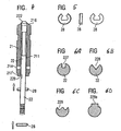
- a fluid injector that is used as a fuel injector for an internal combustion engine, comprises a housing 1 ( Figure 1 ), a valve body 2, an actuator unit 3 and a fuel connector 4.
- the fuel connector 4 is designed to be connected to a high pressure fuel chamber of the internal combustion engine, where fuel is stored under high pressure, for example under the pressure of about 200 Bar.
- the housing 1 is preferably formed out of a double-tubed housing. In the space between the walls of the double-tubed housing the fuel is led from the fuel connector to a fuel inlet 214 of the valve body 2.
- the valve body 2 comprises a cartridge 21, which is permanently fixed to the housing 1 at one of its free ends, preferably by welding, especially laser-welding.
- the cartridge 21 comprises a recess 211 ( Figure 2 ) which forms at one of its ends an injection nozzle 213 and which takes in a needle 22.
- a spring rest 24 is connected to the needle 22.
- a return spring 25 rests on the spring rest 24 and pretensions the needle 22 in a direction away from the injection nozzle 213. In that way the needle 22 closes the injection nozzle 213, if no further external forces act on the needle 22.
- the fuel is led from the fuel inlet 214 in the space between the needle 22 and the wall of the recess 213 of the cartridge 21 to the injection nozzle 213.
- the needle 22 further comprises a guided zone 221, by which the needle 22 is guided within the recess 213.
- the needle 22 rests with its seat area 224 on a needle seat 215 of the cartridge 21.
- the needle seat 215 and the seat area 224 are conically shaped in a preferred embodiment. This enables to set a desired spray angle.
- Areas of the needle 22 and the cartridge 21 facing outwards from the injection nozzle 213 and being adjacent to the injection nozzle 213 are in a preferred embodiment conically shaped and are named in the following conically-shaped area 216 of the cartridge 21 and conically-shaped area 222 of the needle 22. These two conically-shaped areas 216 and 222 need to be precisely aligned in order to prevent the buildup of coking, which decreases the spray quality of the fuel injector. In order to achieve such a precise alignment, the conically-shaped areas 216 and 222 are grinded together which is described in detail below.
- the recess 211 is called in the following first recess 211.
- the needle 22 comprises a recess 226.
- the recess 226 in the needle 22 is formed as a flattening of a section of the cross-section of the needle 22 ( Figure 3 ).
- the recess 226 of the needle 22 has an axial length, that ensures, that the needle 22 can be axially moved by the actuator unit 3 and the return spring 25 as intended.
- FIG. 3 shows a first step of a manufacturing process for an embodiment of the fluid injector.
- the cartridge 21 has a second recess 217'.
- the second recess 217' is formed at an end of the cartridge 21, which is located in the area of the second free end of the first recess 211 with the first free end of the first recess 211 being the injection nozzle 213.
- the needle 22 is inserted into the first recess 211.
- the needle seat 215 of the cartridge 21 and the seat area 224 of the needle 21 are grinded.
- This grinding process preferably includes a lapping process.
- a paste or fluid which contains the cutting material.
- the needle 22 and the cartridge 21 are rotated relatively to each other. By this a very precise finish of the needle seat 215 and the seat area 224 is achieved.
- the holding element which is a ring-shaped element 28 is inserted axially as shown by the arrows of Figure 4 .
- the ring-shaped element 28 ( Figure 5 ) is preferably generally ring-shaped but has a slot which increases flexibility of the ring-shaped element 28 and enables it to be used as a clip element, which is clipped into the recess 226 of the needle 22 and is pushed into the second recess 217. It has contours that match the contour of the second recess 217 of the cartridge 21 and the contour of the recess 226 of the needle 22.
- the ring-shaped element 28 fills out a great part of the space between the needle 22 and the wall of the first recess 211 of the cartridge 21.
- the ring-shaped element 28 has on one hand the function to prevent a rotational movement of the needle 22 relative to the cartridge 21 and on the other hand it dampens effectively pressure waves, which travel along the first recess from the injection nozzle 213 towards the ring-shaped element. This dampening effect relieves parts located even further away from the injection nozzle like a bellow or the actuator unit 3.
- the conically-shaped areas 216, 222 are grinded together in order to get them precisely aligned.
- This grinding process preferably includes a honing process and/or a lapping process.
- the grinding wheel makes, for example, an oscillatory movement, oscillating between the needle 22 and the cartridge21.
- the grinding process may further include a lapping process. After having finished the grinding process the conically-shaped areas 216, 222 precisely match each other.
- the holding element may be kept in the valve body or may also be taken out. Preferably it is left in the valve body, which then ensures during the operation of the injection valve, that there is no rotational movement between the needle 22 and the cartridge 21.
- Figure 6A shows an embodiment of the needle, which is simple to manufacture and ensures in cooperation with the holding element, that the needle 22 is tightly fixed in its rotational position relative to the cartridge 21.
- the recess 228 is formed as a sector.
- the recess 229 is formed in a sinusoidal shape.
- the holding elements, that cooperate with the different forms of the recess 227, 228, 229 or the raised area 229A are formed respectively to enable a rotational fixation of the position of the needle 22.
- the second recess 217' there may also be a raised area which cooperates with the holding element.
Claims (6)
- Corps de soupape comportant une cartouche (21) munie d'une dépression (211), qui forme une buse d'injection (213) sur une extrémité, et avec une aiguille (22), qui est agencée dans le retrait (211) et ferme la buse d'injection (213) lorsqu'elle repose avec sa zone de siège (224) sur un siège d'aiguille (215) de la cartouche (21), comprenant
Une dépression supplémentaire (217, 217') ou une zone surélevée dans la cartouche (21),
un élément de maintien étant un élément de maintien est un élément en forme de bague (28), et
une dépression (226, 227, 228, 229) ou une zone surélevée (229A) dans l'aiguille (22),
la dépression supplémentaire (217, 217') ou la zone surélevée dans la cartouche (21), l'élément de maintien et la dépression (226, 227, 228, 229) ou la zone surélevée (229A) dans l'aiguille (22) étant formés et agencés de façon à coopérer pour fixer l'aiguille (22) dans sa position de rotation par rapport à la cartouche,
l'autre dépression (217, 217') ou zone surélevée dans la cartouche (21) étant formé de sorte que l'élément de maintien fixe l'aiguille (22) à une extrémité de la cartouche (21) à distance de la buse d'injection (213). - Corps de soupape selon la revendication 1, caractérisé en ce que l'élément de maintien est agencé plus loin de la buse d'injection qu'une entrée de fluide.
- Corps de soupape selon l'une des revendications précédentes, caractérisé en ce que la dépression (226, 227, 228, 229) dans l'aiguille (22) est un trou borgne.
- Corps de soupape selon les revendications 1 ou 2, caractérisé en ce que la dépression (226, 227, 228, 229) ou la zone surélevée (229A) dans l'aiguille est formé comme un aplanissement d'une section de la section transversale de l'aiguille (22).
- Injecteur de fluide comportant un boîtier (1), une unité d'actionnement (3) et un corps de soupape (2) selon l'une des revendications précédentes.
- Procédé pour fabriquer un injecteur selon la revendication 5 comprenant les étapes suivantes consistant à :insérer l'aiguille (22) dans la cartouche (21),meuler le siège d'aiguille (215) et la zone de siège (224) de l'aiguille (22),insérer l'élément de maintien,meuler la zone de l'aiguille (22) et de la cartouche (21) faisant face vers l'extérieur depuis la buse d'injection (213) et étant adjacente à la buse d'injection (213), etassembler le corps de soupape (2) avec le boîtier (1).
Priority Applications (2)
| Application Number | Priority Date | Filing Date | Title |
|---|---|---|---|
| EP04001803A EP1559907B2 (fr) | 2004-01-28 | 2004-01-28 | Soupape d'injection avec moyens pour eviter la rotation de l'aiguille |
| DE200460003212 DE602004003212T3 (de) | 2004-01-28 | 2004-01-28 | Einspritzventil mit Mittel, um Ventilnadelrotation zu verhindern |
Applications Claiming Priority (1)
| Application Number | Priority Date | Filing Date | Title |
|---|---|---|---|
| EP04001803A EP1559907B2 (fr) | 2004-01-28 | 2004-01-28 | Soupape d'injection avec moyens pour eviter la rotation de l'aiguille |
Publications (3)
| Publication Number | Publication Date |
|---|---|
| EP1559907A1 EP1559907A1 (fr) | 2005-08-03 |
| EP1559907B1 EP1559907B1 (fr) | 2006-11-15 |
| EP1559907B2 true EP1559907B2 (fr) | 2010-08-11 |
Family
ID=34639395
Family Applications (1)
| Application Number | Title | Priority Date | Filing Date |
|---|---|---|---|
| EP04001803A Expired - Fee Related EP1559907B2 (fr) | 2004-01-28 | 2004-01-28 | Soupape d'injection avec moyens pour eviter la rotation de l'aiguille |
Country Status (2)
| Country | Link |
|---|---|
| EP (1) | EP1559907B2 (fr) |
| DE (1) | DE602004003212T3 (fr) |
Families Citing this family (2)
| Publication number | Priority date | Publication date | Assignee | Title |
|---|---|---|---|---|
| DE102005025522A1 (de) * | 2005-06-03 | 2006-12-07 | Robert Bosch Gmbh | Kraftstoffeinspritzventil für Brennkraftmaschinen |
| EP2246557B1 (fr) * | 2009-04-20 | 2012-06-20 | Continental Automotive GmbH | Injecteur pour injecter un fluide |
Citations (3)
| Publication number | Priority date | Publication date | Assignee | Title |
|---|---|---|---|---|
| GB1005354A (en) † | 1961-06-21 | 1965-09-22 | Emmerich Satzger | Improvements in and relating to fuel injection nozzles |
| GB1329525A (en) † | 1971-04-09 | 1973-09-12 | Gen Motors Corp | Internal combustion engine crank case ventilation valves |
| JP2002089397A (ja) † | 2000-09-12 | 2002-03-27 | Keihin Corp | 電磁式燃料噴射弁 |
Family Cites Families (5)
| Publication number | Priority date | Publication date | Assignee | Title |
|---|---|---|---|---|
| DE3036583A1 (de) * | 1980-09-27 | 1982-05-13 | Robert Bosch Gmbh, 7000 Stuttgart | Kraftstoffeinspritzduese |
| US5127584A (en) * | 1991-05-06 | 1992-07-07 | General Motors Corporation | Fuel injection nozzle |
| EP1041274B1 (fr) * | 1998-10-09 | 2010-09-08 | Jun Arimoto | Valve d'injection de carburant pour moteur diesel |
| US6199539B1 (en) * | 2000-06-22 | 2001-03-13 | Detroit Diesel Corporation | Anti-rotation mechanism for a high pressure fuel supply pipe in a common rail fuel system |
| US6655612B2 (en) * | 2001-01-26 | 2003-12-02 | Siemens Automotive Corporation | Needle/armature rotation limiting feature |
-
2004
- 2004-01-28 EP EP04001803A patent/EP1559907B2/fr not_active Expired - Fee Related
- 2004-01-28 DE DE200460003212 patent/DE602004003212T3/de not_active Expired - Lifetime
Patent Citations (3)
| Publication number | Priority date | Publication date | Assignee | Title |
|---|---|---|---|---|
| GB1005354A (en) † | 1961-06-21 | 1965-09-22 | Emmerich Satzger | Improvements in and relating to fuel injection nozzles |
| GB1329525A (en) † | 1971-04-09 | 1973-09-12 | Gen Motors Corp | Internal combustion engine crank case ventilation valves |
| JP2002089397A (ja) † | 2000-09-12 | 2002-03-27 | Keihin Corp | 電磁式燃料噴射弁 |
Also Published As
| Publication number | Publication date |
|---|---|
| EP1559907A1 (fr) | 2005-08-03 |
| DE602004003212T3 (de) | 2011-03-17 |
| DE602004003212T2 (de) | 2007-03-29 |
| DE602004003212D1 (de) | 2006-12-28 |
| EP1559907B1 (fr) | 2006-11-15 |
Similar Documents
| Publication | Publication Date | Title |
|---|---|---|
| US5607106A (en) | Low inertia, wear-resistant valve for engine fuel injection systems | |
| RU2177075C2 (ru) | Клапан с электромагнитным приводом | |
| EP2103804B1 (fr) | Agencement de couplage | |
| US20110180634A1 (en) | Nozzle body, nozzle assembly and fuel injector, and method for producing a nozzle body | |
| EP2093413B1 (fr) | Dispositif de couplage | |
| EP1559904B1 (fr) | Corps de soupape, injecteur de fluides et procédé de fabrication pour un corps de soupape | |
| US20090229576A1 (en) | Coupling device | |
| EP1559907B2 (fr) | Soupape d'injection avec moyens pour eviter la rotation de l'aiguille | |
| US8713795B2 (en) | Fuel injector remanufacturing method and remanufactured fuel injector | |
| EP1088985A3 (fr) | Injecteur de carburant pour injection directe dans un moteur à combustion interne | |
| EP0972934B1 (fr) | Injecteur de carburant | |
| JP2004518895A (ja) | 噴射弁 | |
| JP2013519027A (ja) | 針弁のための針 | |
| EP1548272B1 (fr) | Corps de soupape pour un injecteur de fluide | |
| EP1998038B1 (fr) | Dispositif de fixation pour fixer un injecteur de combustible dans un tête de cylindre d'un moteur à combustion | |
| EP1794442B1 (fr) | Injecteur de carburant a ressort de valve resistant a perte de vop a applications sur moteur a emissions conformes | |
| JP2023516816A (ja) | 噴射装置用の構成部材および混合物圧縮型の火花点火式の内燃機関のための噴射装置ならびにこのような構成部材を製造する方法 | |
| US4846217A (en) | Injection valve | |
| US20200003170A1 (en) | Fuel Injector With Precluded Fuel Flow at Sac Volume | |
| JP2008038716A (ja) | 燃料噴射弁 | |
| EP1559905A1 (fr) | Injecteur de fluide avec une aiguille de soupape deformable | |
| EP1884657A1 (fr) | Dispositif de fixation d'un injecteur de carburant sur une culasse de moteur à combustion interne | |
| EP1898086B1 (fr) | Ensemble de fixation | |
| JP5035369B2 (ja) | 燃料噴射ノズル | |
| WO2001006114A1 (fr) | Soupape d'injection de carburant |
Legal Events
| Date | Code | Title | Description |
|---|---|---|---|
| PUAI | Public reference made under article 153(3) epc to a published international application that has entered the european phase |
Free format text: ORIGINAL CODE: 0009012 |
|
| AK | Designated contracting states |
Kind code of ref document: A1 Designated state(s): AT BE BG CH CY CZ DE DK EE ES FI FR GB GR HU IE IT LI LU MC NL PT RO SE SI SK TR |
|
| AX | Request for extension of the european patent |
Extension state: AL LT LV MK |
|
| 17P | Request for examination filed |
Effective date: 20060203 |
|
| AKX | Designation fees paid |
Designated state(s): DE FR GB IT |
|
| GRAP | Despatch of communication of intention to grant a patent |
Free format text: ORIGINAL CODE: EPIDOSNIGR1 |
|
| GRAS | Grant fee paid |
Free format text: ORIGINAL CODE: EPIDOSNIGR3 |
|
| GRAA | (expected) grant |
Free format text: ORIGINAL CODE: 0009210 |
|
| AK | Designated contracting states |
Kind code of ref document: B1 Designated state(s): DE FR GB IT |
|
| REG | Reference to a national code |
Ref country code: GB Ref legal event code: FG4D |
|
| REF | Corresponds to: |
Ref document number: 602004003212 Country of ref document: DE Date of ref document: 20061228 Kind code of ref document: P |
|
| ET | Fr: translation filed | ||
| PLBI | Opposition filed |
Free format text: ORIGINAL CODE: 0009260 |
|
| 26 | Opposition filed |
Opponent name: ROBERT BOSCH GMBH Effective date: 20070518 |
|
| PLAX | Notice of opposition and request to file observation + time limit sent |
Free format text: ORIGINAL CODE: EPIDOSNOBS2 |
|
| PLBB | Reply of patent proprietor to notice(s) of opposition received |
Free format text: ORIGINAL CODE: EPIDOSNOBS3 |
|
| RAP2 | Party data changed (patent owner data changed or rights of a patent transferred) |
Owner name: CONTINENTAL AUTOMOTIVE ITALY S.P.A. |
|
| PGFP | Annual fee paid to national office [announced via postgrant information from national office to epo] |
Ref country code: GB Payment date: 20100121 Year of fee payment: 7 |
|
| PUAH | Patent maintained in amended form |
Free format text: ORIGINAL CODE: 0009272 |
|
| STAA | Information on the status of an ep patent application or granted ep patent |
Free format text: STATUS: PATENT MAINTAINED AS AMENDED |
|
| 27A | Patent maintained in amended form |
Effective date: 20100811 |
|
| AK | Designated contracting states |
Kind code of ref document: B2 Designated state(s): DE FR GB IT |
|
| REG | Reference to a national code |
Ref country code: FR Ref legal event code: CD |
|
| GBPC | Gb: european patent ceased through non-payment of renewal fee |
Effective date: 20110128 |
|
| PG25 | Lapsed in a contracting state [announced via postgrant information from national office to epo] |
Ref country code: GB Free format text: LAPSE BECAUSE OF NON-PAYMENT OF DUE FEES Effective date: 20110128 |
|
| REG | Reference to a national code |
Ref country code: FR Ref legal event code: PLFP Year of fee payment: 13 |
|
| REG | Reference to a national code |
Ref country code: FR Ref legal event code: PLFP Year of fee payment: 14 |
|
| REG | Reference to a national code |
Ref country code: FR Ref legal event code: PLFP Year of fee payment: 15 |
|
| PGFP | Annual fee paid to national office [announced via postgrant information from national office to epo] |
Ref country code: DE Payment date: 20180131 Year of fee payment: 15 |
|
| PGFP | Annual fee paid to national office [announced via postgrant information from national office to epo] |
Ref country code: FR Payment date: 20190123 Year of fee payment: 16 Ref country code: IT Payment date: 20190124 Year of fee payment: 16 |
|
| REG | Reference to a national code |
Ref country code: DE Ref legal event code: R119 Ref document number: 602004003212 Country of ref document: DE |
|
| PG25 | Lapsed in a contracting state [announced via postgrant information from national office to epo] |
Ref country code: DE Free format text: LAPSE BECAUSE OF NON-PAYMENT OF DUE FEES Effective date: 20190801 |
|
| PG25 | Lapsed in a contracting state [announced via postgrant information from national office to epo] |
Ref country code: FR Free format text: LAPSE BECAUSE OF NON-PAYMENT OF DUE FEES Effective date: 20200131 |
|
| PG25 | Lapsed in a contracting state [announced via postgrant information from national office to epo] |
Ref country code: IT Free format text: LAPSE BECAUSE OF NON-PAYMENT OF DUE FEES Effective date: 20200128 |