EP1559869B1 - Aube de rotor pour une turbomachine - Google Patents
Aube de rotor pour une turbomachine Download PDFInfo
- Publication number
- EP1559869B1 EP1559869B1 EP05250495A EP05250495A EP1559869B1 EP 1559869 B1 EP1559869 B1 EP 1559869B1 EP 05250495 A EP05250495 A EP 05250495A EP 05250495 A EP05250495 A EP 05250495A EP 1559869 B1 EP1559869 B1 EP 1559869B1
- Authority
- EP
- European Patent Office
- Prior art keywords
- airfoil
- transition
- line
- rotor blade
- curvature
- Prior art date
- Legal status (The legal status is an assumption and is not a legal conclusion. Google has not performed a legal analysis and makes no representation as to the accuracy of the status listed.)
- Ceased
Links
- 230000007704 transition Effects 0.000 claims description 145
- 239000007789 gas Substances 0.000 claims description 7
- 238000005452 bending Methods 0.000 claims description 4
- 230000008901 benefit Effects 0.000 description 7
- 239000000463 material Substances 0.000 description 6
- 238000010276 construction Methods 0.000 description 3
- 238000007689 inspection Methods 0.000 description 3
- 238000004519 manufacturing process Methods 0.000 description 3
- 150000001875 compounds Chemical class 0.000 description 2
- 125000004122 cyclic group Chemical group 0.000 description 1
- 238000013016 damping Methods 0.000 description 1
- 230000007423 decrease Effects 0.000 description 1
- 238000000034 method Methods 0.000 description 1
Images


Classifications
-
- F—MECHANICAL ENGINEERING; LIGHTING; HEATING; WEAPONS; BLASTING
- F01—MACHINES OR ENGINES IN GENERAL; ENGINE PLANTS IN GENERAL; STEAM ENGINES
- F01D—NON-POSITIVE DISPLACEMENT MACHINES OR ENGINES, e.g. STEAM TURBINES
- F01D5/00—Blades; Blade-carrying members; Heating, heat-insulating, cooling or antivibration means on the blades or the members
- F01D5/12—Blades
- F01D5/22—Blade-to-blade connections, e.g. for damping vibrations
- F01D5/225—Blade-to-blade connections, e.g. for damping vibrations by shrouding
-
- F—MECHANICAL ENGINEERING; LIGHTING; HEATING; WEAPONS; BLASTING
- F01—MACHINES OR ENGINES IN GENERAL; ENGINE PLANTS IN GENERAL; STEAM ENGINES
- F01D—NON-POSITIVE DISPLACEMENT MACHINES OR ENGINES, e.g. STEAM TURBINES
- F01D5/00—Blades; Blade-carrying members; Heating, heat-insulating, cooling or antivibration means on the blades or the members
- F01D5/12—Blades
- F01D5/14—Form or construction
- F01D5/141—Shape, i.e. outer, aerodynamic form
- F01D5/142—Shape, i.e. outer, aerodynamic form of the blades of successive rotor or stator blade-rows
- F01D5/143—Contour of the outer or inner working fluid flow path wall, i.e. shroud or hub contour
-
- F—MECHANICAL ENGINEERING; LIGHTING; HEATING; WEAPONS; BLASTING
- F01—MACHINES OR ENGINES IN GENERAL; ENGINE PLANTS IN GENERAL; STEAM ENGINES
- F01D—NON-POSITIVE DISPLACEMENT MACHINES OR ENGINES, e.g. STEAM TURBINES
- F01D5/00—Blades; Blade-carrying members; Heating, heat-insulating, cooling or antivibration means on the blades or the members
- F01D5/12—Blades
- F01D5/14—Form or construction
- F01D5/147—Construction, i.e. structural features, e.g. of weight-saving hollow blades
-
- F—MECHANICAL ENGINEERING; LIGHTING; HEATING; WEAPONS; BLASTING
- F05—INDEXING SCHEMES RELATING TO ENGINES OR PUMPS IN VARIOUS SUBCLASSES OF CLASSES F01-F04
- F05D—INDEXING SCHEME FOR ASPECTS RELATING TO NON-POSITIVE-DISPLACEMENT MACHINES OR ENGINES, GAS-TURBINES OR JET-PROPULSION PLANTS
- F05D2250/00—Geometry
- F05D2250/20—Three-dimensional
- F05D2250/23—Three-dimensional prismatic
- F05D2250/232—Three-dimensional prismatic conical
-
- F—MECHANICAL ENGINEERING; LIGHTING; HEATING; WEAPONS; BLASTING
- F05—INDEXING SCHEMES RELATING TO ENGINES OR PUMPS IN VARIOUS SUBCLASSES OF CLASSES F01-F04
- F05D—INDEXING SCHEME FOR ASPECTS RELATING TO NON-POSITIVE-DISPLACEMENT MACHINES OR ENGINES, GAS-TURBINES OR JET-PROPULSION PLANTS
- F05D2250/00—Geometry
- F05D2250/70—Shape
- F05D2250/71—Shape curved
-
- F—MECHANICAL ENGINEERING; LIGHTING; HEATING; WEAPONS; BLASTING
- F05—INDEXING SCHEMES RELATING TO ENGINES OR PUMPS IN VARIOUS SUBCLASSES OF CLASSES F01-F04
- F05D—INDEXING SCHEME FOR ASPECTS RELATING TO NON-POSITIVE-DISPLACEMENT MACHINES OR ENGINES, GAS-TURBINES OR JET-PROPULSION PLANTS
- F05D2260/00—Function
- F05D2260/94—Functionality given by mechanical stress related aspects such as low cycle fatigue [LCF] of high cycle fatigue [HCF]
- F05D2260/941—Functionality given by mechanical stress related aspects such as low cycle fatigue [LCF] of high cycle fatigue [HCF] particularly aimed at mechanical or thermal stress reduction
-
- Y—GENERAL TAGGING OF NEW TECHNOLOGICAL DEVELOPMENTS; GENERAL TAGGING OF CROSS-SECTIONAL TECHNOLOGIES SPANNING OVER SEVERAL SECTIONS OF THE IPC; TECHNICAL SUBJECTS COVERED BY FORMER USPC CROSS-REFERENCE ART COLLECTIONS [XRACs] AND DIGESTS
- Y02—TECHNOLOGIES OR APPLICATIONS FOR MITIGATION OR ADAPTATION AGAINST CLIMATE CHANGE
- Y02T—CLIMATE CHANGE MITIGATION TECHNOLOGIES RELATED TO TRANSPORTATION
- Y02T50/00—Aeronautics or air transport
- Y02T50/60—Efficient propulsion technologies, e.g. for aircraft
Definitions
- This invention relates to rotor blades of the type used in industrial gas turbine engines, and more specifically, to the tip region of such a rotor blade.
- Gas turbine engines for aircraft have rotor blades that typically are smaller than rotor blades used in, for example, the turbine of an industrial gas turbine that employs steam as a working medium
- the rotor assembly employs such blades with a rotating structure, such as a rotor disk, having an axis of rotation and a plurality of outwardly extending blades. Each blade is disposed about a spanwise axis that extends radially. Generally, the spanwise axis is a radial line referred to as the stacking line which extends outwardly on a radius from the axis of the rotor blade.
- the rotor blade has a base, commonly called a root, which engages the rotating structure at the inner end of the blade.
- the rotor blades each have an airfoil which extends outwardly from the root across the working medium flowpath.
- the rotor blade typically has a shroud extending between airfoils of adjacent rotor blades at the tip region of the rotor blade.
- the shroud has cantilevered wings which extend laterally (circumferentially) between adjacent rotor blades.
- the wings include a portion of a transition zone that extends from the junction with the airfoil and that has an inwardly facing surface which bounds the working medium flowpath.
- the shroud also has a seal land which extends circumferentially in close proximity to adjacent stator structure to block the working medium gases from leaving the flowpath.
- a more rigid member extends between the front and rear portions of the wings to carry the seal land and provide a portion of the transitions zone.
- the shrouds of adjacent rotor blades abut at contact areas on the laterally facing sides of the shroud.
- the abutting shrouds reduce blade deflections about the spanwise axis and minimize vibration of the rotor blades. Damping of the blades takes place through rubbing of the contact faces of adjacent shrouds. Additional rotational loads are created by the mass of the shroud as compared with rotor blades having no shrouds. These rotational loads increase stresses at the shroud airfoil interface because of the sudden change in cross-section of the material and increase stresses at the root-disk interface of the rotor blade and the disk.
- a tip shroud for a rotor blade shroud attached to an airfoil by a transition zone includes wings extending from the sides of the airfoil and a beam which extends past the airfoil for carrying a seal land and between the wings to divide each wing into a front portion and a rear portion,
- the surface contour of a transition zone for a rotor blade shroud at a particular location is defined by the line of intersection of a reference plane (P) with the surface of the transition zone.
- the reference plane is referred to as the normal sectioning plane.
- the reference plane passes through the point at the junction of the transition zone and the airfoil.
- the junction point is usually the point of tangency of the transition zone with the airfoil.
- the reference plane (P) contains a first line perpendicular to the airfoil surface (airfoil section surface) at the junction point and a second line parallel to the stacking line of the airfoil.
- the normal sectioning plane (P) passes through the junction point and is defined by two straight lines passing through the junction point.
- this provides an "X axis" which is a first straight line in the plane of the airfoil section normal (perpendicular) to the surface of the airfoil section; and, a "Y-axis,” which is perpendicular to the first straight line and also parallel to the stacking line of the airfoil.
- transition line The line of intersection of the normal sectioning plane with the transition zone is referred to as a transition line.
- transition line includes straight lines and curved lines. In this application, the line of intersection is viewed perpendicular to the sectioning plane.
- offset ratio The definition of the "offset ratio" for a transition line is the ratio of the length or distance (A) of the projection of the transition line along the X-axis of the sectioning plane divided by the length or distance (B) of the projection of the transition line along the spanwise Y-axis.
- the length (A) is also referred to as the offset distance of the transition line (or transition zone) from the airfoil and the length (B) is referred to as the offset distance of the transition line from the shroud.
- the transition line is a measure of the change in slope per unit length of the transition line as the transition line extends away from the airfoil surface.
- the transition line transition zone
- the transition line has a first end at the junction point with the airfoil and a second end at the location on the shroud where the remainder of the shroud extends in cantilevered fashion from the transition zone.
- This location is where the associated transition line smoothly joins the remainder of the shroud and the instantaneous change in slope is zero, such as at a point of tangency, or where the extension of the transition line on the shroud reverses curvature and bends outwardly.
- This invention is in part predicated on the recognition that a tip shroud for a rotor blade that uses a beam extending laterally past the airfoil for carrying a seal land and supporting a portion of the shroud wings against rotational loads acting on the wings permits contouring the transition zone of the shroud that extends to the airfoil to take advantage of the shifting of part of the loads to the beam by reducing stresses at critical locations while avoiding unacceptably complicating the inspection process of the rotor blade.
- a tip shroud having a wing and beam construction further includes a transition zone that extends from the suction side and pressure side of the airfoil to provide a flow path surface of the shroud, the transition zone having transition lines smoothly recessed from a straight line connecting the ends of the transition line, with those transition lines on at least one side of the airfoil extending under the beam bending more away from the airfoil at a region closer to the airfoil than at a region closer to the side of the shroud such that the average of offset ratios of transition lines that extend under the beam are greater than one and are greater than the average of offset ratios of transition lines that extend only under the rear portion of the wings.
- the offset ratios of transition lines under the beam are greater than the offset ratios of transition lines extending only under the rear portion of the wings.
- the transition lines extending under the beam appear to be formed by part of a conical section but have multiple radii of curvature.
- the transition lines extending under the beam have a first radius of curvature adjacent the airfoil and a second radius of curvature adjacent the shroud that is larger than the first radius of curvature.
- the first and second radii of curvature intersect at a point of tangency.
- the intersection includes a straight line that is tangent to the first and second radii of curvature.
- the intersection includes a curved line that is tangent to the first and second radii of curvature.
- the projected offset distances of the transition line in portions of the transition zone forward or rearward of the beam are smaller than the distances measured at a location under the beam.
- a primary advantage of the present invention is the creep resistance of the shroud to rotational loads under operative conditions which results from providing an offset ratio for transition lines underneath the beam which is greater than one, such as a curve of or an approximation of a curve of a portion of a conical section, to reduce the stress concentration factor at the transition zone and the associated concentrated stress and to provide smaller offset ratios to the wings at locations experiencing lower forces acting on the transition zone.
- Another advantage of one embodiment of the present invention is the ease of manufacture which results from using a transition zone having transition lines that have a single radius of curvature in selected locations that are not under the beam to promote the inspectability of the rotor blade.
- Still another advantage of one embodiment of the present invention is the creep resistance of the shroud coupled with the ease of manufacture which results from providing a transition zone having an offset ratio greater than one with a profile of the transition lines but having a compound radius of curvature (two or more radii of curvature) for ease of inspectability.
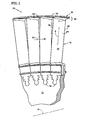
- Fig. 1 is a simplified front elevation view of a rotor assembly (10) of a rotary machine having an axis (Ar).
- the rotor assembly includes a rotating structure, as represented by the disk (12), and a plurality of outwardly extending rotor blades (14).
- Each rotor blade has a root (16) and an airfoil (18) being disposed about a spanwisely extending axis (S), which is commonly called the stacking line (S).
- the airfoil has a pressure side (24) and a suction side (26) as shown in Fig. 3 .
- a flowpath (22) for working medium gases extends through the rotor blades between the sides of the airfoil.
- the rotor blade has a tip region (28) having a tip shroud (30).
- the tip shroud includes a seal land (32) which is a surface having a radius of curvature about the axis (Ar).
- the tip shroud has a transition zone (34) which extends from the sides (24), (26) of the airfoil, as represented by the pressure side (24) shown in Fig. 1 , Fig. 4, and Fig. 5 ; and, the suction side (26) shown in Fig. 4 and Fig. 6 .
- the transition zone includes part of a flowpath surface which extends from a tangent to the pressure side and suction side of the airfoil along a junction (J).
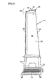
- Fig. 2 is a side elevation view of the rotor blade shown in Fig. 1 .
- the airfoil (18) has a leading edge (36) and a trailing edge (38).
- the tip shroud has a laterally (circumferentially) extending beam (42) which carries the seal land (32).
- Fig. 3 is a top view of a pair of adjacent tip shrouds (30). Each tip shroud has a leading edge region and a trailing edge region.
- the tip shroud includes a depression (48) in the shroud generally radially outwardly of the airfoil and generally following the curve in the tip region of the pressure and suction sides of the airfoil from the leading edge region to the trailing edge region.
- the tip shroud includes a pressure side wing (52) extending from the pressure side of the airfoil having a front portion (52f) and a rear portion (52r). The portions of the wing continue the surface of the depression.
- the pressure side wing has a laterally facing pressure side (56).
- the tip shroud includes a suction side wing (54) extending from the suction side of the airfoil having a front portion (54f) and a rear portion (54r). The portions of the wing continue the surface of the depression.
- the suction side wing (54) has a laterally facing suction side (58).
- the tip shroud further has the beam (42) which has a front face (42f) and a rear face (42r) integral with the wings.
- the beam extends laterally between the wings to divide each wing into the front portion and the rear portion and laterally across the depression to divide the depression into a front portion (48f) and a rear portion (48r).
- the beam further has a pressure side region (62) extending laterally past the pressure side of the airfoil in the tip region of the airfoil, and has a laterally facing pressure side (63) which adapts the beam to engage the suction side (65) of the beam of the adjacent airfoil.
- the beam also has a similar region on the suction side.
- the suction side region (64) extends laterally past the suction side of the airfoil in the tip region of the airfoil, and has a laterally facing suction side which adapts the suction side of the beam to engage the pressure side of the beam of the adjacent airfoil.
- Fig. 4 is a top view of the rotor blade shown in Fig. 3 .
- Fig. 5 and Fig. 6 are side elevation views, respectively, of the pressure side (24) and suction side (26) of the airfoil (18) of the rotor blade shown in Fig. 4 .
- the seal land (32) extends radially outwardly from the beam (42). The seal land reinforces the beam.
- the combination of the seal land (32) and beam (42) extends to support the front and rear portions of the wings (52), (54) providing a portion of the support required against rotational forces acting on the wings under operative conditions.
- the beam and seal land have an inverted T-shaped cross-sectional shape.
- the axial width (Wb) of the beam is greater than four times the axial width (Ws) of the seal land and the radial height (Hs) of the seal land is greater than twice the height of the beam (Hb).
- a fillet radius extends from the front face of the seal land to the front face of the beam and a fillet radius extends from the rear face of the seal land to the rear face of the beam.
- Fig. 5 and Fig. 6 also show the junction (J) of the transition zone with the pressure side (24) and suction side (26) of the airfoil.
- the junction is formed by an infinite number of junction points each at the point of tangency of the transition zone (34) to the airfoil.
- the tangency of the line provides a smooth transition.
- other types of smooth transitions may exist although a tangent is preferred because of the smooth change that occurs.
- a normal sectioning plane (P) is shown.
- the normal sectioning plane has a first line (La) perpendicular to the side of the airfoil at the point of tangency (junction point) and a second line (Lb) passing through the junction point and parallel to the stacking line (S) as discussed earlier.
- the offset distances from the airfoil (A) and from the shroud (B) are shown.
- the transition zone extends much further down on the pressure side of the airfoil than on the suction side of the airfoil.
- Fig. 7 is a view from above of one representative airfoil section.
- the surface of the airfoil is defined by a plurality of these airfoil sections each extending perpendicular to the stacking line (S).
- Fig. 7 shows the relationship of the leading edge and the trailing edge to a chord line having a length (C) which connects the leading edge in the trailing edge.
- a mean chord line extends from the leading edge to the trailing edge about midway between the suction side and the pressure side.
- the leading edge region extends about three percent of the length of the chord line along a line tangent to the mean chord line at the leading edge.
- a trailing edge region extending about three percent of the length of the chord line along a line tangent to the mean chord line at the trailing edge,
- Fig. 7 also shows thirteen normal sectioning planes intersecting the transition zone, each having a line of intersection with the surface of the transition zone. The length of the offset distances from the airfoil (A) is shown. Each sectioning plane shows that the transition zone extends to the side of the wings and under the beam to the extent shown by the curved lines near plane 1 and plane 8.
- the offset ratio is also shown rounded to the nearest hundredths. As can be seen from inspection of the Table, the offset ratio is fairly large and greater than one (A/B>1) on the front portion of the suction side wing and under the beam on the suction side. The ratios underneath the beam on the pressure side are smaller but are also greater than one (A/B>1).
- FIG. 8 is a simplified perspective view from the front in cross-section showing a circular transition line on the pressure side of the airfoil.
- the normal sectioning plane (P) passes through the junction point (J). The view is not taken parallel to the normal sectioning plane.
- Fig. 9 is a similar view from the front in cross-section of an elliptical transition line on the front wing of the pressure side.
- Fig. 10 is another front view similar to Fig. 9.
- Fig. 11 is a rear view in cross section similar to the front view in Fig. 9 but showing the elliptical transition line extending under the beam.
- the transition zone extends from the junction (J) on the pressure side (24) of the airfoil to a line under the beam. Accordingly, the transition zone extending under the beam extends to a location between the pressure side (24) of the airfoil and the pressure side 63 of the beam. Similarly, the transition zone ends at a location on the inwardly facing surface of the suction side region of the beam and between the suction side (26) of the airfoil and the suction side (64) of the beam.
- the transition zone over substantially all of its extent between the leading edge region and the trailing edge region extends to the sides of the wings such that each wing has a cross-sectional shape at a location along a normal sectioning plane that is spanwisely tapered to the sides of the wings, and that is spanwisely tapered under the beam at least as far as the immediately adjacent portion of the wing.
- the transition lines in the transition zone that extended only under the wings covered over ninety-nine percent of the surface area (the flow path area) under the wings with the transition zone. In other embodiments, good results are expected where the transition lines extend to cover over ninety-five percent of the wing area with the transition zone.
- the cross-sectional shape of the transition zone has more than one type of curvature to reduce stresses in the rotor blade as compared to transition zones having one type of curvature for the transition zone.
- offset ratios equal to one provide circular transition lines which on the pressure side of the airfoil decreases surface stresses in the airfoil at the rear portion of the pressure side wing.
- Offset ratios greater than one provide elliptical shaped or true elliptical transition lines reduce stress concentration factors better than circular cross-sections. They are heavier constructions than analogous circular transition lines because more material is placed closer to the shroud at greater radial distance from the axis (Ar).
- Conical section lines that represent the intersection of a plane with a right circular cone form transition lines that have the advantageous benefits of reducing stress concentration factors. These curves may be used to form transition lines.
- Elliptical transition lines are one example.
- Another example are transition lines formed with curves of multiple radii that follow a conical section lines such as an elliptical transition line and may be formed as shown in Fig. 12 . These curves are used on at least one of said sides of the airfoil and show transition lines that extend under the beam that have greater bending away from the airfoil at a region closer to the airfoil on the transition line than at a region closer to the side of the shroud. As a result, and as shown in Fig.
- the average of offset ratios of transition lines that extend under the beam are greater than one and are greater than the average of offset ratios of transition lines that extend only under the rear portion of wings.
- the absolute value of offset ratios of transition lines that extend under the beam is greater than the offset ratios of transition lines that extend only under the rear portion of the wings.
- the transition lines which define the contour of the flow path surface of the shroud for the transition zone of the wing and of the beam follow the shape of part of a conical section. They also have an offset ratio on the suction side of the airfoil for the beam and for the forward portion of the wing that is greater on average than the offset ratio on the pressure side of the airfoil for the beam and for the rear portion of the wing, thus providing a more elliptical flowpath surface on the suction side beam-wing forward region to reduce stress concentration factors in that region.
- Fig. 12 and 13 are examples of a conical transition line and a two radius curve fitted to a conical transition line. As will be realized, more than two curves could be used to generate the same transition line.
Landscapes
- Engineering & Computer Science (AREA)
- Mechanical Engineering (AREA)
- General Engineering & Computer Science (AREA)
- Physics & Mathematics (AREA)
- Fluid Mechanics (AREA)
- Architecture (AREA)
- Turbine Rotor Nozzle Sealing (AREA)
- Wind Motors (AREA)
Claims (15)
- Aube de rotor (14) pour une machine rotative ayant un chemin d'écoulement pour des gaz de fluides de travail, l'aube de rotor ayant une extrémité interne qui comporte une base qui permet à l'aube de rotor d'être réunie à une structure rotative (12), une extrémité externe ayant une surface s'étendant latéralement qui est disposée circonférentiellement autour d'un axe (Ar) et ayant un rayon de courbure autour de l'axe (Ar), une surface portante ayant un bord d'attaque (36), un bord de fuite (38), et un côté aspiration (26) et un côté pression (24) qui s'étendent chacun en forme de corde depuis le bord d'attaque jusqu'au bord de fuite, et une région de pointe (28) qui inclut l'extrémité externe, qui comprend :une pluralité de sections de surface portante disposées en éventail autour de la ligne d'empilement (S) et perpendiculairement à celle-ci pour définir les surfaces de la surface portante,la ligne d'empilement de la surface portante s'étendant en éventail dans une direction radiale,et chaque section de surface portante ayant
un bord d'attaque,
un bord de fuite espacé du bord d'attaque suivant une corde,
un côté aspiration s'étendant depuis le bord d'attaque jusqu'au bord de fuite, et
un côté pression s'étendant depuis le bord d'attaque jusqu'au bord de fuite ;un anneau de pointe (30) pour l'aube de rotor disposé dans la région de pointe, l'anneau de pointe comportant des ailes (52, 54) qui s'étendent depuis les côtés de la surface portante, les ailes comportant
une aile côté pression (52) s'étendant depuis le côté pression (24) de la surface portante ayant une portion avant (52f) et une portion arrière (52r), ayant un côté pression orienté latéralement, et ayant une portion d'une zone de transition (34) qui s'étend depuis le côté pression de la surface portante,
une aile côté aspiration (54) qui s'étend depuis le côté aspiration de la surface portante ayant une portion avant (54f) et une portion arrière (54r), ayant un côté aspiration orienté latéralement, et ayant une portion d'une zone de transition (34) qui s'étend depuis le côté aspiration de la surface portante ;
une poutre (42) d'une seule pièce avec les ailes (52, 54), qui s'étend latéralement entre les ailes pour diviser chaque aile en une portion avant et une portion arrière, la poutre ayant en outre
une région côté pression s'étendant latéralement au-delà du côté pression de la surface portante dans la région de pointe de la surface portante, ayant un côté pression orienté latéralement qui s'adapte à la poutre de manière ce qu'elle s'engage avec le côté aspiration de la poutre de la surface portante adjacente, et ayant une surface orientée vers l'intérieur qui s'étend jusqu'au côté pression de la poutre,
une portion d'une zone de transition (34) qui s'étend depuis le côté pression de la surface portante,
une région côté aspiration qui s'étend latéralement au-delà du côté aspiration de la surface portante dans la région de pointe de la surface portante, ayant un côté aspiration orienté latéralement qui permet au côté aspiration de la poutre de s'engager avec le côté pression de la poutre de la surface portante adjacente, et ayant une surface orientée vers l'intérieur qui s'étend jusqu'au côté pression de la poutre,
une portion d'une zone de transition qui s'étend depuis le côté aspiration de la surface portante,
un méplat d'étanchéité (32) s'étendant radialement vers l'extérieur depuis la poutre (42), le méplat d'étanchéité s'étendant au-delà des côtés de la surface portante entre les portions avant et arrière des ailes et ayant ladite surface orientée vers l'extérieur qui s'étend circonférentiellement par rapport à l'axe (Ar) et qui permet au méplat d'étanchéité de coopérer avec la structure adjacente de la machine rotative pour bloquer la fuite de gaz de fluides de travail devant la région de pointe de l'aube de rotor ; et
une zone de transition (34) formée à partir desdites portions de zone de transition des ailes et de la poutre, la zone de transition s'étendant depuis une jonction avec le côté aspiration et une jonction avec le côté pression de la surface portante pour fournir une surface de chemin d'écoulement de l'anneau qui a un contour lisse ;l'aube de rotor ayant un plan de coupe normal deréférence (P) passant par un point à la jonction de la zone de transition (34) jusqu'à la surfaceportante qui contient une première ligne (La) perpendiculaire au côté de la section de surface portante au niveau de ce point de jonction et une deuxième ligne (Lb) passant à travers ce point de jonction, qui est perpendiculaire à la première ligne et parallèle à la ligne d'empilement de la surface portante ;une ligne de transition étant la ligne d'intersection dudit plan (P) avec la zone de transition (34) au niveau d'un point de jonction et définissant le contour de la surface de la zone de transition en un emplacement particulier ;chaque ligne de transition ayant une distance de décalage de la surface portante (A) qui est la distance de la projection de la ligne de transition le long de la première ligne dudit plan (P) perpendiculairement au côté de la section de surface portante, ayant une distance de décalage de l'anneau (B) qui est la distance de la projection de la ligne de transition le long de la deuxième ligne du plan de coupe parallèlement à la ligne d'empilement, et ayant un rapport de décalage qui est le rapport de la distance de décalage de la surface portante (A) divisée par la distance de décalage de l'anneau (B),chaque ligne de transition ayant une première extrémité au point de jonction et une deuxième extrémité au point où se termine la zone de transition, les lignes de transition étant en retrait régulier depuis une ligne droite reliant les extrémités de la ligne de transition ;caractérisée en ce quesur au moins l'un desdits côtés de la surface portante, les lignes de transition qui s'étendent sous la poutre (42) ont une plus grande courbure à l'écart de la surface portante dans une région plus proche de la surface portante sur la ligne de transition que dans une région plus proche du côté de l'anneau (30), de telle sorte qu'une moyenne des rapports de décalage des lignes de transition qui s'étendent sous la poutre (42) soit supérieure à 1 et soit supérieure à la moyenne des rapports de décalage des lignes de transition qui s'étendent seulement sous la portion arrière des ailes. - Aube de rotor selon la revendication 1, dans laquelle les rapports de décalage des lignes de transition s'étendant sous la poutre (42) sont supérieurs aux rapports de décalage des lignes de transition s'étendant seulement sous les portions arrière des ailes.
- Aube de rotor selon la revendication 1 ou 2, dans laquelle les lignes de transition s'étendant sous La poutre (42) semblent être formées par une partie d'une section conique mais sont approximativement égales à la section conique avec des rayons de courbure multiples.
- Aube de rotor selon la revendication 1, dans laquelle les lignes de transition s'étendant sous la poutre (42) ont un premier rayon de courbure adjacent à la surface portante et un deuxième rayon de courbure adjacent à l'anneau, qui est plus grand que le premier rayon de courbure.
- Aube de rotor selon la revendication 4, dans laquelle les sections des lignes de transition ayant les premier et deuxième rayons de courbure se coupent en un point de tangence avec la ligne de transition.
- Aube de rotor selon la revendication 5, dans laquelle l'intersection inclut une ligne droite qui est tangente aux premier et deuxième rayons de courbure.
- Aube de rotor selon la revendication 5, dans laquelle l'intersection comporte une ligne courbe qui est tangente aux premier et deuxième rayons de courbure.
- Aube de rotor selon la revendication 5, dans laquelle les sections des lignes de transition ayant les premier et deuxième rayons de courbure se coupent en un point de tangence.
- Aube de rotor selon l'une quelconque des revendications précédentes, dans laquelle la zone de transition (34) change uniformément dans la direction de la corde jusqu'à un emplacement en arrière de la poutre (42), auquel la surface de la zone de transition est approximativement égale à un unique rayon de courbure de telle sorte que le rapport de décalage des lignes de transition arrondi au plus proche centième se situe dans une plage de quatre-vingt-dix-huit centièmes à cent deux centièmes (0,98 ≤ rapport de décalage ≤ 1,02) et que la distance de décalage depuis la surface portante (A) de la ligne de transition mesurée par rapport à l'anneau soit approximativement égale à la distance de décalage depuis l'anneau (B) de la zone de transition mesurée par rapport à la surface portante.
- Aube de rotor selon la revendication 9, dans laquelle la zone de transition (34) change uniformément dans la direction de la corde jusqu'à un emplacement en arrière de la poutre, auquel la surface de la zone de transition est un unique rayon de courbure de telle sorte que le rapport de décalage des lignes de transition arrondi au plus proche centième soit de un.
- Aube de rotor selon l'une quelconque des revendications précédentes, dans laquelle les distances de décalage des lignes de transition dans des portions de la zone de transition en avant ou en arrière de la poutre (42) sont plus petites que les distances mesurées en un emplacement sous la poutre.
- Aube de rotor selon l'une quelconque des revendications précédentes, dans laquelle les lignes de transition s'étendant sous la poutre (42) font partie d'une section conique.
- Aube de rotor selon la revendication 12, dans laquelle les lignes de transition s'étendant sous La poutre (42) ont un premier rayon de courbure adjacent à la surface portante et un deuxième rayon de courbure adjacent à l'anneau, qui est plus grand que le premier rayon de courbure.
- Aube de rotor selon la revendication 12, dans laquelle les lignes de transition s'étendant sous la poutre font partie d'une section conique elliptique.
- Aube de rotor selon la revendication 12 ou 14, dans laquelle les lignes de transition s'étendant sous la poutre (42) ont des rayons de courbure multiples.
Applications Claiming Priority (2)
| Application Number | Priority Date | Filing Date | Title |
|---|---|---|---|
| US770323 | 1985-08-27 | ||
| US10/770,323 US7066713B2 (en) | 2004-01-31 | 2004-01-31 | Rotor blade for a rotary machine |
Publications (3)
| Publication Number | Publication Date |
|---|---|
| EP1559869A2 EP1559869A2 (fr) | 2005-08-03 |
| EP1559869A3 EP1559869A3 (fr) | 2008-12-31 |
| EP1559869B1 true EP1559869B1 (fr) | 2011-08-31 |
Family
ID=34654402
Family Applications (1)
| Application Number | Title | Priority Date | Filing Date |
|---|---|---|---|
| EP05250495A Ceased EP1559869B1 (fr) | 2004-01-31 | 2005-01-31 | Aube de rotor pour une turbomachine |
Country Status (5)
| Country | Link |
|---|---|
| US (1) | US7066713B2 (fr) |
| EP (1) | EP1559869B1 (fr) |
| JP (1) | JP2005214206A (fr) |
| CN (1) | CN1648415A (fr) |
| RU (1) | RU2005102767A (fr) |
Families Citing this family (26)
| Publication number | Priority date | Publication date | Assignee | Title |
|---|---|---|---|---|
| EP1515000B1 (fr) * | 2003-09-09 | 2016-03-09 | Alstom Technology Ltd | Aubage d'une turbomachine avec un carenage contouré |
| US7134838B2 (en) * | 2004-01-31 | 2006-11-14 | United Technologies Corporation | Rotor blade for a rotary machine |
| US7396205B2 (en) * | 2004-01-31 | 2008-07-08 | United Technologies Corporation | Rotor blade for a rotary machine |
| WO2006002464A1 (fr) * | 2004-07-01 | 2006-01-12 | Ringprop Trading Limited | Interface de pale d'helice carenee ou renforcee |
| US20090097979A1 (en) * | 2007-07-31 | 2009-04-16 | Omer Duane Erdmann | Rotor blade |
| USD611510S1 (en) * | 2007-08-28 | 2010-03-09 | Alstom Technology Ltd. | Turbo machine blade platform |
| USD586831S1 (en) * | 2007-08-28 | 2009-02-17 | Alstom Technology Ltd. | Turbo machine double blade and platform |
| US8057186B2 (en) * | 2008-04-22 | 2011-11-15 | General Electric Company | Shape for a turbine bucket tip shroud |
| US8371816B2 (en) * | 2009-07-31 | 2013-02-12 | General Electric Company | Rotor blades for turbine engines |
| US8721289B2 (en) * | 2009-10-30 | 2014-05-13 | General Electric Company | Flow balancing slot |
| KR101305575B1 (ko) | 2010-01-20 | 2013-09-09 | 미츠비시 쥬고교 가부시키가이샤 | 터빈 동익 및 터보 기계 |
| CH702980A1 (de) * | 2010-03-31 | 2011-10-14 | Alstom Technology Ltd | Dichtstruktur an einem Deckband einer Turbinenlaufschaufel. |
| US8641381B2 (en) * | 2010-04-14 | 2014-02-04 | General Electric Company | System and method for reducing grain boundaries in shrouded airfoils |
| US20130209258A1 (en) * | 2012-02-15 | 2013-08-15 | General Electric Company | Tip shrouded blade |
| US9322282B2 (en) * | 2012-11-30 | 2016-04-26 | General Electric Company | Fillet for use with a turbine rotor blade tip shroud |
| US9683446B2 (en) | 2013-03-07 | 2017-06-20 | Rolls-Royce Energy Systems, Inc. | Gas turbine engine shrouded blade |
| CN103422906B (zh) * | 2013-08-29 | 2015-04-08 | 哈尔滨工程大学 | 一种具有s形叶冠动叶片的涡轮 |
| EP3052764B1 (fr) * | 2013-10-03 | 2024-04-10 | RTX Corporation | Module inter-turbines avec une pluralité d'aubes statoriques. |
| US9879550B2 (en) | 2014-07-31 | 2018-01-30 | Pratt & Whitney Canada Corp. | Outer shroud with gusset |
| EP2987956A1 (fr) * | 2014-08-18 | 2016-02-24 | Siemens Aktiengesellschaft | Aube de compresseur |
| US10648346B2 (en) * | 2016-07-06 | 2020-05-12 | General Electric Company | Shroud configurations for turbine rotor blades |
| US10472974B2 (en) | 2017-02-14 | 2019-11-12 | General Electric Company | Turbomachine rotor blade |
| US10526899B2 (en) | 2017-02-14 | 2020-01-07 | General Electric Company | Turbine blade having a tip shroud |
| US10400610B2 (en) * | 2017-02-14 | 2019-09-03 | General Electric Company | Turbine blade having a tip shroud notch |
| CN109630461A (zh) * | 2018-11-29 | 2019-04-16 | 中国航发沈阳黎明航空发动机有限责任公司 | 一种低压压气机工作叶片凸肩结构 |
| JP7289745B2 (ja) * | 2019-07-11 | 2023-06-12 | 三菱重工業株式会社 | 動翼、及びこれを備えている軸流回転機械 |
Family Cites Families (11)
| Publication number | Priority date | Publication date | Assignee | Title |
|---|---|---|---|---|
| GB1605335A (en) * | 1975-08-23 | 1991-12-18 | Rolls Royce | A rotor blade for a gas turbine engine |
| JP3150526B2 (ja) | 1994-02-23 | 2001-03-26 | 三菱重工業株式会社 | ガスタービン動翼のシュラウド |
| JP4051132B2 (ja) * | 1998-05-25 | 2008-02-20 | 株式会社東芝 | タービン動翼 |
| EP1041247B1 (fr) * | 1999-04-01 | 2012-08-01 | General Electric Company | Aube de turbineà gaz comprenant un circuit de refroidissement ouvert |
| JP2001055902A (ja) | 1999-08-18 | 2001-02-27 | Toshiba Corp | タービン動翼 |
| US6241471B1 (en) * | 1999-08-26 | 2001-06-05 | General Electric Co. | Turbine bucket tip shroud reinforcement |
| US6491498B1 (en) | 2001-10-04 | 2002-12-10 | Power Systems Mfg, Llc. | Turbine blade pocket shroud |
| US6805530B1 (en) * | 2003-04-18 | 2004-10-19 | General Electric Company | Center-located cutter teeth on shrouded turbine blades |
| US6890150B2 (en) * | 2003-08-12 | 2005-05-10 | General Electric Company | Center-located cutter teeth on shrouded turbine blades |
| US6857853B1 (en) * | 2003-08-13 | 2005-02-22 | General Electric Company | Conical tip shroud fillet for a turbine bucket |
| US6913445B1 (en) * | 2003-12-12 | 2005-07-05 | General Electric Company | Center located cutter teeth on shrouded turbine blades |
-
2004
- 2004-01-31 US US10/770,323 patent/US7066713B2/en not_active Expired - Lifetime
-
2005
- 2005-01-28 JP JP2005020493A patent/JP2005214206A/ja active Pending
- 2005-01-28 RU RU2005102767/06A patent/RU2005102767A/ru not_active Application Discontinuation
- 2005-01-31 EP EP05250495A patent/EP1559869B1/fr not_active Ceased
- 2005-01-31 CN CNA2005100061646A patent/CN1648415A/zh active Pending
Also Published As
| Publication number | Publication date |
|---|---|
| US7066713B2 (en) | 2006-06-27 |
| CN1648415A (zh) | 2005-08-03 |
| RU2005102767A (ru) | 2006-07-10 |
| EP1559869A3 (fr) | 2008-12-31 |
| JP2005214206A (ja) | 2005-08-11 |
| EP1559869A2 (fr) | 2005-08-03 |
| US20050169758A1 (en) | 2005-08-04 |
Similar Documents
| Publication | Publication Date | Title |
|---|---|---|
| EP1559871B1 (fr) | Aube de rotor pour une turbomachine | |
| EP1559869B1 (fr) | Aube de rotor pour une turbomachine | |
| EP1152122B1 (fr) | Jeu d'aubes de turbomachine | |
| US7625181B2 (en) | Turbine cascade structure | |
| US5221181A (en) | Stationary turbine blade having diaphragm construction | |
| US6890150B2 (en) | Center-located cutter teeth on shrouded turbine blades | |
| US8911215B2 (en) | Compressor blade for an axial compressor | |
| US7134838B2 (en) | Rotor blade for a rotary machine | |
| US6506022B2 (en) | Turbine blade having a cooled tip shroud | |
| EP2476862B1 (fr) | Aube statorique pour turbomachine à flux axial et turbomachine associée | |
| US4460315A (en) | Turbomachine rotor assembly | |
| US9017030B2 (en) | Turbine component including airfoil with contour | |
| KR20040095671A (ko) | 터빈 버킷 및 터빈 | |
| US20060275134A1 (en) | Blade of axial flow-type rotary fluid machine | |
| CN100406681C (zh) | 涡轮叶片顶部覆环边缘轮廓 | |
| US10704392B2 (en) | Tip shroud fillets for turbine rotor blades | |
| EP1559870B1 (fr) | Aube de rotor carénée pour une turbomachine | |
| US12196110B2 (en) | Blisk for a gas turbine | |
| CN111911240B (zh) | 护罩互锁装置 | |
| US20230383662A1 (en) | Annulus contouring | |
| CA2091696A1 (fr) | Aubage stationnaire pour turbine a vapeur de construction a diaphragme | |
| CA2113062A1 (fr) | Aubes a profil aerodynamique pour turbine a vapeur |
Legal Events
| Date | Code | Title | Description |
|---|---|---|---|
| PUAI | Public reference made under article 153(3) epc to a published international application that has entered the european phase |
Free format text: ORIGINAL CODE: 0009012 |
|
| AK | Designated contracting states |
Kind code of ref document: A2 Designated state(s): AT BE BG CH CY CZ DE DK EE ES FI FR GB GR HU IE IS IT LI LT LU MC NL PL PT RO SE SI SK TR |
|
| AX | Request for extension of the european patent |
Extension state: AL BA HR LV MK YU |
|
| PUAL | Search report despatched |
Free format text: ORIGINAL CODE: 0009013 |
|
| AK | Designated contracting states |
Kind code of ref document: A3 Designated state(s): AT BE BG CH CY CZ DE DK EE ES FI FR GB GR HU IE IS IT LI LT LU MC NL PL PT RO SE SI SK TR |
|
| AX | Request for extension of the european patent |
Extension state: AL BA HR LV MK YU |
|
| 17P | Request for examination filed |
Effective date: 20090406 |
|
| AKX | Designation fees paid |
Designated state(s): DE GB |
|
| 17Q | First examination report despatched |
Effective date: 20091127 |
|
| GRAP | Despatch of communication of intention to grant a patent |
Free format text: ORIGINAL CODE: EPIDOSNIGR1 |
|
| GRAS | Grant fee paid |
Free format text: ORIGINAL CODE: EPIDOSNIGR3 |
|
| GRAA | (expected) grant |
Free format text: ORIGINAL CODE: 0009210 |
|
| AK | Designated contracting states |
Kind code of ref document: B1 Designated state(s): DE GB |
|
| REG | Reference to a national code |
Ref country code: GB Ref legal event code: FG4D |
|
| REG | Reference to a national code |
Ref country code: DE Ref legal event code: R081 Ref document number: 602005029836 Country of ref document: DE Owner name: UNITED TECHNOLOGIES CORP. (N.D.GES.D. STAATES , US Free format text: FORMER OWNER: UNITED TECHNOLOGIES CORP. (N.D.GES.D. STAATES DELAWARE), HARTFORD, CONN., US |
|
| REG | Reference to a national code |
Ref country code: DE Ref legal event code: R096 Ref document number: 602005029836 Country of ref document: DE Effective date: 20111027 |
|
| PLBE | No opposition filed within time limit |
Free format text: ORIGINAL CODE: 0009261 |
|
| STAA | Information on the status of an ep patent application or granted ep patent |
Free format text: STATUS: NO OPPOSITION FILED WITHIN TIME LIMIT |
|
| 26N | No opposition filed |
Effective date: 20120601 |
|
| REG | Reference to a national code |
Ref country code: DE Ref legal event code: R097 Ref document number: 602005029836 Country of ref document: DE Effective date: 20120601 |
|
| REG | Reference to a national code |
Ref country code: DE Ref legal event code: R082 Ref document number: 602005029836 Country of ref document: DE Representative=s name: SCHMITT-NILSON SCHRAUD WAIBEL WOHLFROM PATENTA, DE |
|
| REG | Reference to a national code |
Ref country code: DE Ref legal event code: R082 Ref document number: 602005029836 Country of ref document: DE Representative=s name: SCHMITT-NILSON SCHRAUD WAIBEL WOHLFROM PATENTA, DE Ref country code: DE Ref legal event code: R081 Ref document number: 602005029836 Country of ref document: DE Owner name: UNITED TECHNOLOGIES CORP. (N.D.GES.D. STAATES , US Free format text: FORMER OWNER: UNITED TECHNOLOGIES CORPORATION, HARTFORD, CONN., US |
|
| PGFP | Annual fee paid to national office [announced via postgrant information from national office to epo] |
Ref country code: DE Payment date: 20191218 Year of fee payment: 16 Ref country code: GB Payment date: 20191223 Year of fee payment: 16 |
|
| REG | Reference to a national code |
Ref country code: DE Ref legal event code: R119 Ref document number: 602005029836 Country of ref document: DE |
|
| GBPC | Gb: european patent ceased through non-payment of renewal fee |
Effective date: 20210131 |
|
| PG25 | Lapsed in a contracting state [announced via postgrant information from national office to epo] |
Ref country code: DE Free format text: LAPSE BECAUSE OF NON-PAYMENT OF DUE FEES Effective date: 20210803 Ref country code: GB Free format text: LAPSE BECAUSE OF NON-PAYMENT OF DUE FEES Effective date: 20210131 |