EP1559871B1 - Aube de rotor pour une turbomachine - Google Patents
Aube de rotor pour une turbomachine Download PDFInfo
- Publication number
- EP1559871B1 EP1559871B1 EP05250504.7A EP05250504A EP1559871B1 EP 1559871 B1 EP1559871 B1 EP 1559871B1 EP 05250504 A EP05250504 A EP 05250504A EP 1559871 B1 EP1559871 B1 EP 1559871B1
- Authority
- EP
- European Patent Office
- Prior art keywords
- airfoil
- transition
- transition zone
- rotor blade
- line
- Prior art date
- Legal status (The legal status is an assumption and is not a legal conclusion. Google has not performed a legal analysis and makes no representation as to the accuracy of the status listed.)
- Ceased
Links
- 230000007704 transition Effects 0.000 claims description 110
- 239000000463 material Substances 0.000 claims description 12
- 239000007789 gas Substances 0.000 claims description 6
- 230000008901 benefit Effects 0.000 description 6
- 238000010276 construction Methods 0.000 description 3
- 238000005452 bending Methods 0.000 description 2
- 238000007689 inspection Methods 0.000 description 2
- 240000006829 Ficus sundaica Species 0.000 description 1
- 230000001154 acute effect Effects 0.000 description 1
- 150000001875 compounds Chemical class 0.000 description 1
- 125000004122 cyclic group Chemical group 0.000 description 1
- 238000013016 damping Methods 0.000 description 1
- 230000007423 decrease Effects 0.000 description 1
- 238000004519 manufacturing process Methods 0.000 description 1
Images


Classifications
-
- F—MECHANICAL ENGINEERING; LIGHTING; HEATING; WEAPONS; BLASTING
- F01—MACHINES OR ENGINES IN GENERAL; ENGINE PLANTS IN GENERAL; STEAM ENGINES
- F01D—NON-POSITIVE DISPLACEMENT MACHINES OR ENGINES, e.g. STEAM TURBINES
- F01D11/00—Preventing or minimising internal leakage of working-fluid, e.g. between stages
- F01D11/08—Preventing or minimising internal leakage of working-fluid, e.g. between stages for sealing space between rotor blade tips and stator
-
- F—MECHANICAL ENGINEERING; LIGHTING; HEATING; WEAPONS; BLASTING
- F01—MACHINES OR ENGINES IN GENERAL; ENGINE PLANTS IN GENERAL; STEAM ENGINES
- F01D—NON-POSITIVE DISPLACEMENT MACHINES OR ENGINES, e.g. STEAM TURBINES
- F01D5/00—Blades; Blade-carrying members; Heating, heat-insulating, cooling or antivibration means on the blades or the members
- F01D5/12—Blades
- F01D5/14—Form or construction
- F01D5/141—Shape, i.e. outer, aerodynamic form
- F01D5/142—Shape, i.e. outer, aerodynamic form of the blades of successive rotor or stator blade-rows
- F01D5/143—Contour of the outer or inner working fluid flow path wall, i.e. shroud or hub contour
-
- F—MECHANICAL ENGINEERING; LIGHTING; HEATING; WEAPONS; BLASTING
- F01—MACHINES OR ENGINES IN GENERAL; ENGINE PLANTS IN GENERAL; STEAM ENGINES
- F01D—NON-POSITIVE DISPLACEMENT MACHINES OR ENGINES, e.g. STEAM TURBINES
- F01D5/00—Blades; Blade-carrying members; Heating, heat-insulating, cooling or antivibration means on the blades or the members
- F01D5/12—Blades
- F01D5/14—Form or construction
- F01D5/147—Construction, i.e. structural features, e.g. of weight-saving hollow blades
-
- F—MECHANICAL ENGINEERING; LIGHTING; HEATING; WEAPONS; BLASTING
- F01—MACHINES OR ENGINES IN GENERAL; ENGINE PLANTS IN GENERAL; STEAM ENGINES
- F01D—NON-POSITIVE DISPLACEMENT MACHINES OR ENGINES, e.g. STEAM TURBINES
- F01D5/00—Blades; Blade-carrying members; Heating, heat-insulating, cooling or antivibration means on the blades or the members
- F01D5/12—Blades
- F01D5/22—Blade-to-blade connections, e.g. for damping vibrations
- F01D5/225—Blade-to-blade connections, e.g. for damping vibrations by shrouding
-
- F—MECHANICAL ENGINEERING; LIGHTING; HEATING; WEAPONS; BLASTING
- F05—INDEXING SCHEMES RELATING TO ENGINES OR PUMPS IN VARIOUS SUBCLASSES OF CLASSES F01-F04
- F05D—INDEXING SCHEME FOR ASPECTS RELATING TO NON-POSITIVE-DISPLACEMENT MACHINES OR ENGINES, GAS-TURBINES OR JET-PROPULSION PLANTS
- F05D2250/00—Geometry
- F05D2250/20—Three-dimensional
- F05D2250/23—Three-dimensional prismatic
- F05D2250/232—Three-dimensional prismatic conical
-
- F—MECHANICAL ENGINEERING; LIGHTING; HEATING; WEAPONS; BLASTING
- F05—INDEXING SCHEMES RELATING TO ENGINES OR PUMPS IN VARIOUS SUBCLASSES OF CLASSES F01-F04
- F05D—INDEXING SCHEME FOR ASPECTS RELATING TO NON-POSITIVE-DISPLACEMENT MACHINES OR ENGINES, GAS-TURBINES OR JET-PROPULSION PLANTS
- F05D2250/00—Geometry
- F05D2250/70—Shape
- F05D2250/71—Shape curved
-
- F—MECHANICAL ENGINEERING; LIGHTING; HEATING; WEAPONS; BLASTING
- F05—INDEXING SCHEMES RELATING TO ENGINES OR PUMPS IN VARIOUS SUBCLASSES OF CLASSES F01-F04
- F05D—INDEXING SCHEME FOR ASPECTS RELATING TO NON-POSITIVE-DISPLACEMENT MACHINES OR ENGINES, GAS-TURBINES OR JET-PROPULSION PLANTS
- F05D2260/00—Function
- F05D2260/94—Functionality given by mechanical stress related aspects such as low cycle fatigue [LCF] of high cycle fatigue [HCF]
- F05D2260/941—Functionality given by mechanical stress related aspects such as low cycle fatigue [LCF] of high cycle fatigue [HCF] particularly aimed at mechanical or thermal stress reduction
-
- Y—GENERAL TAGGING OF NEW TECHNOLOGICAL DEVELOPMENTS; GENERAL TAGGING OF CROSS-SECTIONAL TECHNOLOGIES SPANNING OVER SEVERAL SECTIONS OF THE IPC; TECHNICAL SUBJECTS COVERED BY FORMER USPC CROSS-REFERENCE ART COLLECTIONS [XRACs] AND DIGESTS
- Y02—TECHNOLOGIES OR APPLICATIONS FOR MITIGATION OR ADAPTATION AGAINST CLIMATE CHANGE
- Y02T—CLIMATE CHANGE MITIGATION TECHNOLOGIES RELATED TO TRANSPORTATION
- Y02T50/00—Aeronautics or air transport
- Y02T50/60—Efficient propulsion technologies, e.g. for aircraft
-
- Y—GENERAL TAGGING OF NEW TECHNOLOGICAL DEVELOPMENTS; GENERAL TAGGING OF CROSS-SECTIONAL TECHNOLOGIES SPANNING OVER SEVERAL SECTIONS OF THE IPC; TECHNICAL SUBJECTS COVERED BY FORMER USPC CROSS-REFERENCE ART COLLECTIONS [XRACs] AND DIGESTS
- Y10—TECHNICAL SUBJECTS COVERED BY FORMER USPC
- Y10S—TECHNICAL SUBJECTS COVERED BY FORMER USPC CROSS-REFERENCE ART COLLECTIONS [XRACs] AND DIGESTS
- Y10S416/00—Fluid reaction surfaces, i.e. impellers
- Y10S416/02—Formulas of curves
Definitions
- This invention relates to rotor blades of the type used in industrial gas turbine engines, and more specifically, to the tip region of such a rotor blade.
- Gas turbine engines for aircraft have rotor blades that typically are smaller than rotor blades used in, for example, the turbine of an industrial gas turbine that employs steam as a working medium
- the rotor assembly employs such blades with a rotating structure, such as a rotor disk, having an axis of rotation and a plurality of outwardly extending blades. Each blade is disposed about a spanwise axis that extends radially. Generally, the spanwise axis is a radial line referred to as the stacking line which extends outwardly on a radius from the axis of the rotor blade.
- the rotor blade has a base, commonly called a root, which engages the rotating structure at the inner end of the blade.
- the rotor blades each have an airfoil which extends outwardly from the root across the working medium flowpath.
- the rotor blade typically has a shroud extending between airfoils of adjacent rotor blades at the tip region of the rotor blade.
- the shroud has cantilevered wings which extend laterally (circumferentially) between adjacent rotor blades.
- the wings include a portion of a transition zone that extends from the junction with the airfoil and that has an inwardly facing surface which bounds the working medium flowpath.
- the shroud also has a seal land which extends circumferentially in close proximity to adjacent stator structure to block the working medium gases from leaving the flowpath.
- a more rigid member extends between the front and rear portions of the wings to carry the seal land and provide a portion of the transitions zone.
- the shrouds of adjacent rotor blades abut at contact areas on the laterally facing sides of the shroud.
- the abutting shrouds reduce blade deflections about the spanwise axis and minimize vibration of the rotor blades. Damping of the blades takes place through rubbing of the contact faces of adjacent shrouds. Additional rotational loads are created by the mass of the shroud as compared with rotor blades having no shrouds. These rotational loads increase stresses at the shroud airfoil interface because of the sudden change in cross-section of the material and increase stresses at the root-disk interface of the rotor blade and the disk.
- a rotor blade having the features of the preamble of claim 1 is disclosed in JP 07233703 A .
- a tip shroud for a rotor blade shroud attached to an airfoil by a transition zone includes wings extending from the sides of the airfoil and a beam which extends past the airfoil for carrying a seal land and between the wings to divide each wing into a front portion and a rear portion.
- the surface contour of a transition zone for a rotor blade shroud at a particular location is defined by the line of intersection of a reference plane P with the surface of the transition zone.
- the reference plane is referred to as the normal sectioning plane.
- the reference plane passes through the point at the junction of the transition zone and the airfoil, The junction point is usually the point of tangency of the transition zone with the airfoil.
- the reference plane P contains a first line perpendicular to the airfoil surface (airfoil section surface) at the junction point and a second line parallel to the stacking line of the airfoil.
- the normal sectioning plane P passes through the junction point and is defined by two straight lines passing through the junction point.
- this provides an "X axis" which is a first straight line in the plane of the airfoil section normal (perpendicular) to the surface of the airfoil section; and, a "Y-axis,” which is perpendicular to the first straight line and also parallel to the stacking line of the airfoil.
- transition line The line of intersection of the normal sectioning plane with the transition zone is referred to as a transition line.
- transition line includes straight lines and curved lines. In this application, the line of intersection is viewed perpendicular to the sectioning plane.
- offset ratio The definition of the "offset ratio" for a transition line is the ratio of the length or distance "A" of the projection of the transition line along the X-axis of the sectioning plane divided by the length or distance "B" of the projection of the transition line along the spanwise Y-axis.
- the length A is also referred to as the offset distance of the transition line (or transition zone) from the airfoil and the length B is referred to as the offset distance of the transition line from the shroud.
- the transition line is a measure of the change in slope per unit length of the transition line as the transition line extends away from the airfoil surface.
- the transition line transition zone
- the transition line has a first end at the junction point with the airfoil and a second end at the location on the shroud where the remainder of the shroud extends in cantilevered fashion from the transition zone.
- This location is where the associated transition line smoothly joins the remainder of the shroud and the instantaneous change in slope is zero, such as at a point of tangency, or where the extension of the transition line on the shroud reverses curvature and bends outwardly.
- a rotor blade that includes an airfoil having a leading edge region and a trailing edge region, that includes a tip shroud having wings extending from the sides of the airfoils and that includes a beam which carries a seal land, the beam being integral with the wings and extending between the wings to divide each wing into a front portion and a rear portion may use the beam to partly support the wings against rotational forces acting on the wings, and may use a transition zone that extends from the sides of the airfoil to provide part of the flow path surface of the shroud, to support the shroud from the airfoil, and, in supporting the shroud, to be tailored to reduce stresses in the rotor blade as compared to transition zones having one type of curvature for the transition zone.
- a tip shroud having a wing and beam construction further includes a transition zone that extends from the sides of the airfoil to provide a flow path surface of the shroud, the transition zone over substantially all of its extent between the leading edge region and the trailing edge region extending to the sides of the wings such that each wing has a cross-sectional shape along a normal sectioning plane which is spanwisely tapered to the side of the wing and which is spanwisely tapered under the beam at least as far as the adjacent portion of the wing.
- the transition zone extends over 99 percent of the flow path area of the portion of the wings that are located between the leading-edge region and the trailing edge region.
- the transition zone does not extend to the side of the beam and the beam extends laterally in cantilevered fashion from the transition zone.
- the beam has a cross-sectional shape perpendicular to the lateral direction that is an inverted T-section to provide additional support to the remainder of the beam.
- the offset ratio for the beam-forward wing portion of the suction side varies from about 1.2 to about 1.5 and the offset ratio of the beam-rear wing portion varies from about 1.0 to about 1.2.
- the stacking line of the airfoil is inclined in the direction of rotation away from a radial line of the rotor blade, and the shroud forms an obtuse angle with the suction side of the airfoil and forms an acute angle with the pressure side of the airfoil.
- a primary advantage of the present invention is the creep resistance of the shroud of a rotor blade which results from positively supporting the wings of the shroud with a transition zone over substantially all of the flowpath surface of the shroud between the leading edge region and the trailing edge region.
- Another advantage is the fatigue life of the rotor blade resulting from the level of concentrated stresses associated with the stress concentration factor caused by the transition zone beneath the beam and forward of the beam on the suction side of the airfoil by providing an offset ratio which is greater than one at those locations to reduce the stress concentration factor and by transferring a portion of the rotational loads acting on the wings to the beam to permit using a transition zone along the pressure side of the airfoil adjacent the rear wing whose contour follows a portion of a circle or nearly circular configuration to provide more transition zone material to reduce surface stresses in the pressure side of the airfoil.
- an advantage is the fatigue life resulting from the level of stresses in the rear transition zones adjacent the laterally thinner part of the airfoil which results from transferring a portion of the loads acting on the rear wings through the inverted T-section of the beam to the transition zone underneath the beam which has been contoured to provide an offset ratio which reduces the stress concentration factor as compared to a circular transition zone.
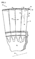
- Fig. 1 is a simplified front elevation view of a rotor assembly 10 of a rotary machine having an axis Ar.
- the rotor assembly includes a rotating structure, as represented by the disk 12, and a plurality of outwardly extending rotor blades 14.
- Each rotor blade has a root 16 and an airfoil 18 being disposed about a spanwisely extending axis S, which is commonly called the stacking line S.
- the airfoil has a pressure side 24 and a suction side 26 as shown in Fig. 3 .
- a flowpath 22 for working medium gases extends through the rotor blades between the sides of the airfoil.
- the rotor blade has a tip region 28 having a tip shroud 30.
- the tip shroud includes a seal land 32 which is a surface having a radius of curvature about the axis Ar.
- the tip shroud has a transition zone 34 which extends from the sides 24, 26 of the airfoil, as represented by the pressure side 24 shown in Fig. 1 , Fig. 4, and Fig. 5 ; and, the suction side 26 shown in Fig. 4 and Fig. 6 .
- the transition zone includes part of a flowpath surface which extends from a tangent to the pressure side and suction side of the airfoil along a junction J.
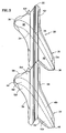
- Fig. 2 is a side elevation view of the rotor blade shown in Fig. 1 .
- the airfoil 18 has a leading edge 36 and a trailing edge 38.
- the tip shroud has a laterally (circumferentially) extending beam 42 which carries the seal land 32.
- Fig. 3 is a top view of a pair of adjacent tip shrouds 30.
- Each tip shroud has a leading edge region and a trailing edge region.
- the tip shroud includes a depression 48 in the shroud generally radially outwardly of the airfoil and generally following the curve in the tip region of the pressure and suction sides of the airfoil from the leading edge region to the trailing edge region.
- the tip shroud includes a pressure side wing 52 extending from the pressure side of the airfoil having a front portion 52f and a rear portion 52r. The portions of the wing continue the surface of the depression.
- the pressure side wing has a laterally facing pressure side 56.
- the tip shroud includes a suction side wing 54 extending from the suction side of the airfoil having a front portion 54f and a rear portion 54r. The portions of the wing continue the surface of the depression.
- the suction side wing 54 has a laterally facing suction side 58.
- the tip shroud further has the beam 42 which has a front face 42f and a rear face 42r integral with the wings.
- the beam extends laterally between the wings to divide each wing into the front portion and the rear portion and laterally across the depression to divide the depression into a front portion 48f and a rear portion 48r.
- the beam further has a pressure side region 62 extending laterally past the pressure side of the airfoil in the tip region of the airfoil, and has a laterally facing pressure side 63 which adapts the beam to engage the suction side 65 of the beam of the adjacent airfoil.
- the beam also has a similar region on the suction side.
- the suction side region 64 extends laterally past the suction side of the airfoil in the tip region of the airfoil, and has a laterally facing suction side which adapts the suction side of the beam to engage the pressure side of the beam of the adjacent airfoil.
- Fig. 4 is a top view of the rotor blade shown in Fig. 3 .
- Fig. 5 and Fig. 6 are side elevation views, respectively, of the pressure side 24 and suction side 26 of the airfoil 18 of the rotor blade shown in Fig. 4 .
- the seal land 32 extends radially outwardly from the beam 42.
- the seal land reinforces the beam.
- the combination of the seal land 32 and beam 42 extends to support the front and rear portions of the wings 52, 54 providing a portion of the support required against rotational forces acting on the wings under operative conditions.
- the beam and seal land have an inverted T-shaped cross-sectional shape.
- the axial width Wb of the beam is greater than four times the axial width Ws of the seal land and the radial height Hs of the seal land is greater than twice the height of the beam Hb.
- a fillet radius extends from the front face of the seal land to the front face of the beam and a fillet radius extends from the rear face of the seal land to the rear face of the beam.
- Fig. 5 and Fig. 6 also show the junction J of the transition zone with the pressure side 24 and suction side 26 of the airfoil.
- the junction is formed by an infinite number of junction points each at the point of tangency of the transition zone 34 to the airfoil.
- the tangency of the line provides a smooth transition.
- other types of smooth transitions may exist although a tangent is preferred because of the smooth change that occurs.
- a normal sectioning plane P is shown.
- the normal sectioning plane has a first line La perpendicular to the side of the airfoil at the point of tangency (junction point) and a second line Lb passing through the junction point and parallel to the stacking line S as discussed earlier.
- the offset distances A and B are shown.
- the transition zone extends much further down on the pressure side of the airfoil than on the suction side of the airfoil.
- Fig. 7 is a view from above of one representative airfoil section.
- the surface of the airfoil is defined by a plurality of these airfoil sections each extending perpendicular to the stacking line S.
- Fig. 7 shows the relationship of the leading edge and the trailing edge to a chord line having a length C which connects the leading edge in the trailing edge.
- a mean chord line extends from the leading edge to the trailing edge about midway between the suction side and the pressure side.
- the leading edge region extends about three percent of the length of the chord line along a line tangent to the mean chord line at the leading edge.
- a trailing edge region extending about three percent of the length of the chord line along a line tangent to the mean chord line at the trailing edge,
- Fig. 7 also shows thirteen normal sectioning planes intersecting the transition zone, each having a line of intersection with the surface of the transition zone. The length of the offset distances A is shown. Each sectioning plane shows that the transition zone extends to the side of the wings and under the beam to the extent shown by the curved lines near plane 1 (B 1) and plane 8 (B 8).
- the offset ratio is also shown rounded to the nearest hundredths. As can be seen from inspection of the Table, the offset ratio is fairly large and greater than one (A/B>1) on the front portion of th e suction side wing and under the beam on the suction side. The ratios underneath the beam on the pressure side are smaller but are also greater than one (A/B>1) .
- Fig. 8 is a simplified perspective view from the front in cross-section showing a circular transition line on the pressure side of the airfoil.
- the normal sectioning plane P passes through the junction point J .
- the view is not taken parallel to the normal sectioning plane.
- Fig. 9 is a similar view from the front in cross-section of an elliptical transition line on the front wing of the pressure side.
- Fig. 10 is another front view similar to Fig. 9.
- Fig. 11 is a rear view in cross section similar to the front view in Fig. 9 but showing the elliptical transition line extending under the beam.
- the transition zone extends from the junction J on the pressure side 24 of the airfoil to a line B8 under the beam. Accordingly, the transition zone extending under the beam extends to a location between the pressure side 24 of the airfoil and the pressure side 63 of the beam. Similarly, the transition zone ends at a location along the line B 1 on the inwardly facing surface of the suction side region of the beam and between the suction side 26 of the airfoil and the suction side 64 of the beam.
- the transition zone over substantially all of its extent between the leading edge region and the trailing edge region extends to the sides of the wings such that each wing has a cross-sectional shape at a location along a normal sectioning plane that is spanwisely tapered to the sides of the wings, and that is spanwisely tapered under the beam at least as far as the immediately adjacent portion of the wing.
- the transition lines in the transition zone that extended only under the wings covered over ninety-nine (99) percent of the surface area (the flow path area) under the wings with the transition zone. In other embodiments, good results are expected where the transition lines extend to cover over ninety-five (95) percent of the wing area with the transition zone.
- the cross-sectional shape of the transition zone has more than one type of curvature to reduce stresses in the rotor blade as compared to transition zones having one type of curvature for the transition zone.
- offset ratios equal to one provide circular transition lines which on the pressure side of the airfoil decreases surface stresses in the airfoil at the rear portion of the pressure side wing.
- Offset ratios greater than one provide elliptical shaped or true elliptical transition lines reduce stress concentration factors better than circular cross-sections. They are heavier constructions than analogous circular transition lines because more material is placed closer to the shroud at greater radial distance from the axis Ar.
- Conical section lines that represent the intersection of a plane with a right circular cone form transition lines that have the advantageous benefits of reducing stress concentration factors. These curves may be used to form transition lines.
- Elliptical transition lines are one example.
- Another example are transition lines formed with curves of multiple radii that follow a conical section lines such as an elliptical transition line and may be formed as shown in Fig. 12 . These curves are used on at least one of said sides of the airfoil and show transition lines that extend under the beam that have greater bending away from the airfoil at a region closer to the airfoil on the transition line than at a region closer to the side of the shroud. As a result, and as shown in Fig.
- the average of offset ratios Rb of transition lines that extend under the beam are greater than one and are greater than the average of offset ratios Rw of transition lines that extend only under the rear portion of wings.
- the absolute value of the transition lines Rb is greater than the ratios Rw.
- the transition lines which define the contour of the flow path surface of the shroud for the transition zone of the wing and of the beam follow the shape of part of a conical section. They also have an offset ratio on the suction side of the airfoil for the beam Rb and for the forward portion of the wing Rw that is greater on average than the offset ratio on the pressure side of the airfoil for the beam Rb and for the rear portion of the wing Rw, thus providing a more elliptical flowpath surface on the suction side beam-wing forward region to reduce stress concentration factors in that region.
- They also provide a mo re circular flowpath surface on the pressure side for the beam -rear wing portion to provide transition zone material that extends down the airfoil, the offset distance B, for at least 80% of the length that the material extends laterally on the shroud, offset distance A, to reduce airfoil surface stresses as compared to an airfoil not having such a length of shroud material.
- Fig. 12 and 13 are examples of a conical transition line and a two radius curve fitted to a conical transition line. As will be realized, more than two curves could be used to generate the same transition line.
Landscapes
- Engineering & Computer Science (AREA)
- Mechanical Engineering (AREA)
- General Engineering & Computer Science (AREA)
- Physics & Mathematics (AREA)
- Fluid Mechanics (AREA)
- Architecture (AREA)
- Turbine Rotor Nozzle Sealing (AREA)
- Structures Of Non-Positive Displacement Pumps (AREA)
Claims (6)
- Aube de rotor (14) pour une machine rotative ayant un chemin d'écoulement pour des fluides de travail gazeux, l'aube de rotor ayant un axe (Ar) et une région de pointe ayant un méplat d'étanchéité s'étendant latéralement (32), comprenant :une surface portante ayant une ligne de superposition (S) qui s'étend radialement et une pluralité de sections de surface portante perpendiculaires à la ligne de superposition, qui définissent la forme de la surface portante,chaque section de surface portante ayant un bord d'attaque, un bord de fuite espacé du bord d'attaque dans le sens de la corde, une région de bord d'attaque, une région de bord de fuite ; un côté d'aspiration et un côté de pression, chacun s'étendant depuis le bord d'attaque jusqu'au bord de fuite ; etun carénage de pointe (30) ayant une aile du côté d'aspiration (54) et une aile du côté de pression (52) s'étendant depuis les côtés des surfaces portantes, chaque aile ayant un côté qui est généralement orienté dans la direction latérale, etune poutre (42) ayant des côtés orientés latéralement, laquelle poutre porte le méplat d'étanchéité (32), le méplat d'étanchéité s'étendant radialement vers l'extérieur depuis la poutre, la poutre étant formée intégralement avec les ailes et s'étendant entre les ailes pour diviser chaque aile en une portion avant et une portion arrière ; etune zone de transition (34) qui s'étend depuis les côtés de la surface portante pour fournir une surface de chemin d'écoulement du carénage et pour fournir une transition du matériau de la surface portante au matériau du carénage ;l'aube de rotor ayant un plan de coupe normal de référence (P) passant par un point au niveau de la jonction de la zone de transition à la surface portante qui contient une première ligne (La) perpendiculaire au côté de la section de surface portante au niveau de ce point de jonction et une deuxième ligne (Lb) passant par ce point de jonction, qui est perpendiculaire à la première ligne et parallèle à la ligne de superposition de la surface portante ;la zone de transition (34) sur substantiellement toute son étendue entre la région de bord d'attaque et la région de bord de fuite s'étendant vers les côtés des ailes de telle sorte que chaque aile ait une forme en section transversale en un emplacement le long d'un plan de coupe normal, qui est effilée dans le sens de l'envergure vers les côtés des ailes et qui est effilée dans le sens de l'envergure sous la poutre au moins jusqu'à la portion de l'aile immédiatement adjacente ;la forme en section transversale de la zone de transition (34) ayant plus d'un type de courbure pour réduire les contraintes dans l'aube de rotor par comparaison avec des zones de transition ayant un type de courbure pour la zone de transition, la zone de transition comportant des lignes de transition définies comme étant des lignes d'intersection du plan de coupe normal avec les lignes de transition de la zone de transition (34) sur le côté d'aspiration de la surface portante sous la poutre (42) et en avant de la poutre (42) ayant un rapport de décalage défini comme le rapport de la longueur de la projection de la ligne de transition le long d'un premier axe (X) qui est une ligne droite dans le plan de la section de surface portante perpendiculaire à la surface de la section de surface portante, sur la projection de la ligne de transition le long d'un deuxième axe (Y) qui est perpendiculaire au premier axe (X) et parallèle à l'axe de superposition de la surface portante, qui est supérieur à 1 ; etcaractérisée en ce que :des lignes de transition le long du côté de pression de la surface portante au niveau de la portion arrière (52r) de l'aile du côté de pression (52) ont des configurations circulaires.
- Aube de rotor selon la revendication 1, dans laquelle la zone de transition (34) s'étend sur quatre-vingt-dix pour cent (90) de la surface du chemin d'écoulement de la portion des ailes (52, 54) qui sont situées entre la région de bord d'attaque et la région de bord de fuite.
- Aube de rotor selon la revendication 1, dans laquelle la zone de transition s'étend sur quatre-vingt-dix-neuf pour cent (99) de la surface du chemin d'écoulement de la portion des ailes (52, 54) qui sont situées entre la région de bord d'attaque et la région de bord de fuite.
- Aube de rotor selon l'une quelconque des revendications précédentes, dans laquelle la zone de transition (34) ne s'étend pas jusqu'au côté de la poutre (42) et la poutre (42) s'étend latéralement en porte-à-faux depuis la zone de transition.
- Aube de rotor selon la revendication 4, dans laquelle la poutre (42) et le méplat d'étanchéité (32) ont une forme en section transversale en forme de T inversé orientée dans la direction latérale.
- Aube de rotor selon la revendication 5, dans laquelle la largeur axiale (Wb) de la poutre (42) est supérieure à quatre fois la largeur axiale (Ws) du méplat d'étanchéité (32) et la hauteur radiale (Hs) du méplat d'étanchéité est supérieure à deux fois la hauteur (Hb) de la poutre avec un rayon de congé s'étendant depuis la face avant du méplat d'étanchéité jusqu'à la face avant de la poutre et un rayon de congé s'étendant depuis la face arrière du méplat d'étanchéité jusqu'à la face arrière de la poutre.
Applications Claiming Priority (2)
| Application Number | Priority Date | Filing Date | Title |
|---|---|---|---|
| US10/770,331 US7396205B2 (en) | 2004-01-31 | 2004-01-31 | Rotor blade for a rotary machine |
| US770331 | 2004-01-31 |
Publications (3)
| Publication Number | Publication Date |
|---|---|
| EP1559871A2 EP1559871A2 (fr) | 2005-08-03 |
| EP1559871A3 EP1559871A3 (fr) | 2009-01-07 |
| EP1559871B1 true EP1559871B1 (fr) | 2013-05-22 |
Family
ID=34654403
Family Applications (1)
| Application Number | Title | Priority Date | Filing Date |
|---|---|---|---|
| EP05250504.7A Ceased EP1559871B1 (fr) | 2004-01-31 | 2005-01-31 | Aube de rotor pour une turbomachine |
Country Status (5)
| Country | Link |
|---|---|
| US (1) | US7396205B2 (fr) |
| EP (1) | EP1559871B1 (fr) |
| JP (1) | JP2005214207A (fr) |
| CN (1) | CN1648416A (fr) |
| RU (2) | RU2005102768A (fr) |
Families Citing this family (53)
| Publication number | Priority date | Publication date | Assignee | Title |
|---|---|---|---|---|
| US7134838B2 (en) * | 2004-01-31 | 2006-11-14 | United Technologies Corporation | Rotor blade for a rotary machine |
| US7762779B2 (en) * | 2006-08-03 | 2010-07-27 | General Electric Company | Turbine blade tip shroud |
| FR2923524B1 (fr) * | 2007-11-12 | 2013-12-06 | Snecma | Aube metallique fabriquee par moulage et procede de fabrication de l'aube |
| JP5308077B2 (ja) * | 2008-06-10 | 2013-10-09 | 三菱重工業株式会社 | タービンおよびタービン動翼 |
| US8371816B2 (en) * | 2009-07-31 | 2013-02-12 | General Electric Company | Rotor blades for turbine engines |
| US8721289B2 (en) * | 2009-10-30 | 2014-05-13 | General Electric Company | Flow balancing slot |
| KR101411177B1 (ko) * | 2009-12-07 | 2014-06-23 | 미츠비시 쥬고교 가부시키가이샤 | 터빈 및 터빈 동익 |
| JP5297540B2 (ja) * | 2010-01-20 | 2013-09-25 | 三菱重工業株式会社 | タービン動翼及びターボ機械 |
| US8807928B2 (en) * | 2011-10-04 | 2014-08-19 | General Electric Company | Tip shroud assembly with contoured seal rail fillet |
| US9109455B2 (en) * | 2012-01-20 | 2015-08-18 | General Electric Company | Turbomachine blade tip shroud |
| ES2581753T3 (es) | 2012-03-15 | 2016-09-07 | Mtu Aero Engines Gmbh | Segmento de corona de álabes con superficie de delimitación de espacio anular con un perfil de altura ondulado así como procedimiento para fabricar el mismo |
| US9885368B2 (en) | 2012-05-24 | 2018-02-06 | Carrier Corporation | Stall margin enhancement of axial fan with rotating shroud |
| MY176943A (en) * | 2012-08-22 | 2020-08-27 | United Technologies Corp | Compliant cantilevered airfoil |
| US9683446B2 (en) | 2013-03-07 | 2017-06-20 | Rolls-Royce Energy Systems, Inc. | Gas turbine engine shrouded blade |
| US10502229B2 (en) | 2014-02-19 | 2019-12-10 | United Technologies Corporation | Gas turbine engine airfoil |
| US10393139B2 (en) | 2014-02-19 | 2019-08-27 | United Technologies Corporation | Gas turbine engine airfoil |
| WO2015126449A1 (fr) | 2014-02-19 | 2015-08-27 | United Technologies Corporation | Surface portante de moteur à turbine à gaz |
| WO2015126715A1 (fr) | 2014-02-19 | 2015-08-27 | United Technologies Corporation | Profil aérodynamique de turbine à gaz |
| WO2015126941A1 (fr) | 2014-02-19 | 2015-08-27 | United Technologies Corporation | Profil aérodynamique de moteur à turbine à gaz |
| US9567858B2 (en) | 2014-02-19 | 2017-02-14 | United Technologies Corporation | Gas turbine engine airfoil |
| US10465702B2 (en) | 2014-02-19 | 2019-11-05 | United Technologies Corporation | Gas turbine engine airfoil |
| WO2015126452A1 (fr) | 2014-02-19 | 2015-08-27 | United Technologies Corporation | Surface portante de moteur à turbine à gaz |
| US10557477B2 (en) | 2014-02-19 | 2020-02-11 | United Technologies Corporation | Gas turbine engine airfoil |
| US10590775B2 (en) | 2014-02-19 | 2020-03-17 | United Technologies Corporation | Gas turbine engine airfoil |
| EP3108105B1 (fr) | 2014-02-19 | 2021-05-12 | Raytheon Technologies Corporation | Surface portante pour turbine à gaz |
| WO2015175073A2 (fr) | 2014-02-19 | 2015-11-19 | United Technologies Corporation | Surface portante de moteur à turbine à gaz |
| WO2015175051A2 (fr) | 2014-02-19 | 2015-11-19 | United Technologies Corporation | Profil aérodynamique de moteur à turbine à gaz |
| WO2015126837A1 (fr) | 2014-02-19 | 2015-08-27 | United Technologies Corporation | Profil aérodynamique de moteur à turbine à gaz |
| WO2015126451A1 (fr) | 2014-02-19 | 2015-08-27 | United Technologies Corporation | Surface portante de moteur à turbine à gaz |
| EP3108121B1 (fr) | 2014-02-19 | 2023-09-06 | Raytheon Technologies Corporation | Moteur à double flux à engrenage avec aubes de compresseur basse pression |
| EP3108113A4 (fr) | 2014-02-19 | 2017-03-15 | United Technologies Corporation | Profil aérodynamique de turbine à gaz |
| US10605259B2 (en) | 2014-02-19 | 2020-03-31 | United Technologies Corporation | Gas turbine engine airfoil |
| EP3108110B1 (fr) | 2014-02-19 | 2020-04-22 | United Technologies Corporation | Surface portante pour turbine à gaz |
| WO2015126454A1 (fr) | 2014-02-19 | 2015-08-27 | United Technologies Corporation | Surface portante de moteur à turbine à gaz |
| US10352331B2 (en) | 2014-02-19 | 2019-07-16 | United Technologies Corporation | Gas turbine engine airfoil |
| EP3108114B1 (fr) | 2014-02-19 | 2021-12-08 | Raytheon Technologies Corporation | Profil d'aube pour moteur à turbine à gaz |
| JP6066948B2 (ja) * | 2014-03-13 | 2017-01-25 | 三菱重工業株式会社 | シュラウド、動翼体、及び回転機械 |
| US10876415B2 (en) | 2014-06-04 | 2020-12-29 | Raytheon Technologies Corporation | Fan blade tip as a cutting tool |
| US9879550B2 (en) | 2014-07-31 | 2018-01-30 | Pratt & Whitney Canada Corp. | Outer shroud with gusset |
| EP2987956A1 (fr) * | 2014-08-18 | 2016-02-24 | Siemens Aktiengesellschaft | Aube de compresseur |
| US10053993B2 (en) * | 2015-03-17 | 2018-08-21 | Siemens Energy, Inc. | Shrouded turbine airfoil with leakage flow conditioner |
| US10156149B2 (en) | 2016-02-09 | 2018-12-18 | General Electric Company | Turbine nozzle having fillet, pinbank, throat region and profile |
| US10190417B2 (en) | 2016-02-09 | 2019-01-29 | General Electric Company | Turbine bucket having non-axisymmetric endwall contour and profile |
| US10196908B2 (en) | 2016-02-09 | 2019-02-05 | General Electric Company | Turbine bucket having part-span connector and profile |
| US10161255B2 (en) | 2016-02-09 | 2018-12-25 | General Electric Company | Turbine nozzle having non-axisymmetric endwall contour (EWC) |
| US10190421B2 (en) * | 2016-02-09 | 2019-01-29 | General Electric Company | Turbine bucket having tip shroud fillet, tip shroud cross-drilled apertures and profile |
| US10001014B2 (en) | 2016-02-09 | 2018-06-19 | General Electric Company | Turbine bucket profile |
| US10221710B2 (en) | 2016-02-09 | 2019-03-05 | General Electric Company | Turbine nozzle having non-axisymmetric endwall contour (EWC) and profile |
| US10125623B2 (en) | 2016-02-09 | 2018-11-13 | General Electric Company | Turbine nozzle profile |
| US10526899B2 (en) * | 2017-02-14 | 2020-01-07 | General Electric Company | Turbine blade having a tip shroud |
| US10294801B2 (en) | 2017-07-25 | 2019-05-21 | United Technologies Corporation | Rotor blade having anti-wear surface |
| US10704392B2 (en) * | 2018-03-23 | 2020-07-07 | General Electric Company | Tip shroud fillets for turbine rotor blades |
| JP2021059997A (ja) * | 2019-10-04 | 2021-04-15 | 三菱重工業株式会社 | 動翼、及びこれを備えている軸流回転機械 |
Family Cites Families (21)
| Publication number | Priority date | Publication date | Assignee | Title |
|---|---|---|---|---|
| GB1605335A (en) * | 1975-08-23 | 1991-12-18 | Rolls Royce | A rotor blade for a gas turbine engine |
| DE3842710C1 (fr) * | 1988-12-19 | 1989-08-03 | Mtu Muenchen Gmbh | |
| DE4015206C1 (fr) * | 1990-05-11 | 1991-10-17 | Mtu Muenchen Gmbh | |
| JP3150526B2 (ja) | 1994-02-23 | 2001-03-26 | 三菱重工業株式会社 | ガスタービン動翼のシュラウド |
| US5391118A (en) * | 1994-05-24 | 1995-02-21 | Dayco Products, Inc. | Belt tensioner, actuator therefor and methods of making the same |
| US5525038A (en) * | 1994-11-04 | 1996-06-11 | United Technologies Corporation | Rotor airfoils to control tip leakage flows |
| US5762673A (en) * | 1997-01-24 | 1998-06-09 | Hoya Precision Inc. | Method of manufacturing glass optical elements |
| EP1041247B1 (fr) * | 1999-04-01 | 2012-08-01 | General Electric Company | Aube de turbineà gaz comprenant un circuit de refroidissement ouvert |
| US6290465B1 (en) * | 1999-07-30 | 2001-09-18 | General Electric Company | Rotor blade |
| JP2001055902A (ja) | 1999-08-18 | 2001-02-27 | Toshiba Corp | タービン動翼 |
| US6241471B1 (en) | 1999-08-26 | 2001-06-05 | General Electric Co. | Turbine bucket tip shroud reinforcement |
| DE10062954B4 (de) * | 2000-12-16 | 2004-04-15 | Schott Glas | Vorrichtung zum Erzeugen von Glasgobs |
| US6554572B2 (en) * | 2001-05-17 | 2003-04-29 | General Electric Company | Gas turbine engine blade |
| US6491498B1 (en) | 2001-10-04 | 2002-12-10 | Power Systems Mfg, Llc. | Turbine blade pocket shroud |
| US6805530B1 (en) | 2003-04-18 | 2004-10-19 | General Electric Company | Center-located cutter teeth on shrouded turbine blades |
| US6890150B2 (en) | 2003-08-12 | 2005-05-10 | General Electric Company | Center-located cutter teeth on shrouded turbine blades |
| US6857853B1 (en) * | 2003-08-13 | 2005-02-22 | General Electric Company | Conical tip shroud fillet for a turbine bucket |
| US7063509B2 (en) * | 2003-09-05 | 2006-06-20 | General Electric Company | Conical tip shroud fillet for a turbine bucket |
| US6913445B1 (en) | 2003-12-12 | 2005-07-05 | General Electric Company | Center located cutter teeth on shrouded turbine blades |
| US7134838B2 (en) * | 2004-01-31 | 2006-11-14 | United Technologies Corporation | Rotor blade for a rotary machine |
| US7066713B2 (en) * | 2004-01-31 | 2006-06-27 | United Technologies Corporation | Rotor blade for a rotary machine |
-
2004
- 2004-01-31 US US10/770,331 patent/US7396205B2/en not_active Expired - Lifetime
-
2005
- 2005-01-28 RU RU2005102768/06A patent/RU2005102768A/ru not_active Application Discontinuation
- 2005-01-28 RU RU2005102766/06A patent/RU2005102766A/ru not_active Application Discontinuation
- 2005-01-28 JP JP2005020494A patent/JP2005214207A/ja active Pending
- 2005-01-31 CN CNA2005100061754A patent/CN1648416A/zh active Pending
- 2005-01-31 EP EP05250504.7A patent/EP1559871B1/fr not_active Ceased
Also Published As
| Publication number | Publication date |
|---|---|
| JP2005214207A (ja) | 2005-08-11 |
| US7396205B2 (en) | 2008-07-08 |
| EP1559871A3 (fr) | 2009-01-07 |
| RU2005102766A (ru) | 2006-07-10 |
| US20050169761A1 (en) | 2005-08-04 |
| RU2005102768A (ru) | 2006-07-10 |
| CN1648416A (zh) | 2005-08-03 |
| EP1559871A2 (fr) | 2005-08-03 |
Similar Documents
| Publication | Publication Date | Title |
|---|---|---|
| EP1559871B1 (fr) | Aube de rotor pour une turbomachine | |
| EP1559869B1 (fr) | Aube de rotor pour une turbomachine | |
| EP1152122B1 (fr) | Jeu d'aubes de turbomachine | |
| US5221181A (en) | Stationary turbine blade having diaphragm construction | |
| US7625181B2 (en) | Turbine cascade structure | |
| US7887297B2 (en) | Airfoil array with an endwall protrusion and components of the array | |
| US6890150B2 (en) | Center-located cutter teeth on shrouded turbine blades | |
| US8647066B2 (en) | Blade with non-axisymmetric platform: recess and boss on the extrados | |
| US8911215B2 (en) | Compressor blade for an axial compressor | |
| US7134838B2 (en) | Rotor blade for a rotary machine | |
| US4460315A (en) | Turbomachine rotor assembly | |
| US9017030B2 (en) | Turbine component including airfoil with contour | |
| US20110014056A1 (en) | Blade with non-axisymmetric platform | |
| US5035578A (en) | Blading for reaction turbine blade row | |
| US20150147179A1 (en) | Blade with 3d platform comprising an inter-blade bulb | |
| US20190292913A1 (en) | Tip shroud fillets for turbine rotor blades | |
| US20130156562A1 (en) | Turbomachine and turbomachine stage | |
| EP1559870B1 (fr) | Aube de rotor carénée pour une turbomachine | |
| US12196110B2 (en) | Blisk for a gas turbine | |
| CN111911240B (zh) | 护罩互锁装置 | |
| US20030118447A1 (en) | Bladed member, in particular for an axial turbine of an aircraft engine | |
| US20230383662A1 (en) | Annulus contouring | |
| CA2091696A1 (fr) | Aubage stationnaire pour turbine a vapeur de construction a diaphragme | |
| CA2113062A1 (fr) | Aubes a profil aerodynamique pour turbine a vapeur |
Legal Events
| Date | Code | Title | Description |
|---|---|---|---|
| PUAI | Public reference made under article 153(3) epc to a published international application that has entered the european phase |
Free format text: ORIGINAL CODE: 0009012 |
|
| AK | Designated contracting states |
Kind code of ref document: A2 Designated state(s): AT BE BG CH CY CZ DE DK EE ES FI FR GB GR HU IE IS IT LI LT LU MC NL PL PT RO SE SI SK TR |
|
| AX | Request for extension of the european patent |
Extension state: AL BA HR LV MK YU |
|
| PUAL | Search report despatched |
Free format text: ORIGINAL CODE: 0009013 |
|
| AK | Designated contracting states |
Kind code of ref document: A3 Designated state(s): AT BE BG CH CY CZ DE DK EE ES FI FR GB GR HU IE IS IT LI LT LU MC NL PL PT RO SE SI SK TR |
|
| AX | Request for extension of the european patent |
Extension state: AL BA HR LV MK YU |
|
| 17P | Request for examination filed |
Effective date: 20090406 |
|
| AKX | Designation fees paid |
Designated state(s): DE GB |
|
| 17Q | First examination report despatched |
Effective date: 20091127 |
|
| GRAP | Despatch of communication of intention to grant a patent |
Free format text: ORIGINAL CODE: EPIDOSNIGR1 |
|
| GRAS | Grant fee paid |
Free format text: ORIGINAL CODE: EPIDOSNIGR3 |
|
| GRAA | (expected) grant |
Free format text: ORIGINAL CODE: 0009210 |
|
| AK | Designated contracting states |
Kind code of ref document: B1 Designated state(s): DE GB |
|
| REG | Reference to a national code |
Ref country code: DE Ref legal event code: R081 Ref document number: 602005039663 Country of ref document: DE Owner name: UNITED TECHNOLOGIES CORP. (N.D.GES.D. STAATES , US Free format text: FORMER OWNER: UNITED TECHNOLOGIES CORP. (N.D.GES.D. STAATES DELAWARE), HARTFORD, CONN., US Ref country code: GB Ref legal event code: FG4D |
|
| REG | Reference to a national code |
Ref country code: DE Ref legal event code: R096 Ref document number: 602005039663 Country of ref document: DE Effective date: 20130711 |
|
| PLBE | No opposition filed within time limit |
Free format text: ORIGINAL CODE: 0009261 |
|
| STAA | Information on the status of an ep patent application or granted ep patent |
Free format text: STATUS: NO OPPOSITION FILED WITHIN TIME LIMIT |
|
| 26N | No opposition filed |
Effective date: 20140225 |
|
| REG | Reference to a national code |
Ref country code: DE Ref legal event code: R097 Ref document number: 602005039663 Country of ref document: DE Effective date: 20140225 |
|
| REG | Reference to a national code |
Ref country code: DE Ref legal event code: R082 Ref document number: 602005039663 Country of ref document: DE Representative=s name: SCHMITT-NILSON SCHRAUD WAIBEL WOHLFROM PATENTA, DE |
|
| REG | Reference to a national code |
Ref country code: DE Ref legal event code: R082 Ref document number: 602005039663 Country of ref document: DE Representative=s name: SCHMITT-NILSON SCHRAUD WAIBEL WOHLFROM PATENTA, DE Ref country code: DE Ref legal event code: R081 Ref document number: 602005039663 Country of ref document: DE Owner name: UNITED TECHNOLOGIES CORP. (N.D.GES.D. STAATES , US Free format text: FORMER OWNER: UNITED TECHNOLOGIES CORPORATION, HARTFORD, CONN., US |
|
| PGFP | Annual fee paid to national office [announced via postgrant information from national office to epo] |
Ref country code: DE Payment date: 20191218 Year of fee payment: 16 Ref country code: GB Payment date: 20191223 Year of fee payment: 16 |
|
| REG | Reference to a national code |
Ref country code: DE Ref legal event code: R119 Ref document number: 602005039663 Country of ref document: DE |
|
| GBPC | Gb: european patent ceased through non-payment of renewal fee |
Effective date: 20210131 |
|
| PG25 | Lapsed in a contracting state [announced via postgrant information from national office to epo] |
Ref country code: GB Free format text: LAPSE BECAUSE OF NON-PAYMENT OF DUE FEES Effective date: 20210131 Ref country code: DE Free format text: LAPSE BECAUSE OF NON-PAYMENT OF DUE FEES Effective date: 20210803 |