EP1559858A2 - Vehicle hood hinge - Google Patents
Vehicle hood hinge Download PDFInfo
- Publication number
- EP1559858A2 EP1559858A2 EP05001203A EP05001203A EP1559858A2 EP 1559858 A2 EP1559858 A2 EP 1559858A2 EP 05001203 A EP05001203 A EP 05001203A EP 05001203 A EP05001203 A EP 05001203A EP 1559858 A2 EP1559858 A2 EP 1559858A2
- Authority
- EP
- European Patent Office
- Prior art keywords
- lever
- hood
- hinge mechanism
- hinge
- coupled
- Prior art date
- Legal status (The legal status is an assumption and is not a legal conclusion. Google has not performed a legal analysis and makes no representation as to the accuracy of the status listed.)
- Withdrawn
Links
Images


Classifications
-
- B—PERFORMING OPERATIONS; TRANSPORTING
- B60—VEHICLES IN GENERAL
- B60R—VEHICLES, VEHICLE FITTINGS, OR VEHICLE PARTS, NOT OTHERWISE PROVIDED FOR
- B60R21/00—Arrangements or fittings on vehicles for protecting or preventing injuries to occupants or pedestrians in case of accidents or other traffic risks
- B60R21/34—Protecting non-occupants of a vehicle, e.g. pedestrians
- B60R21/38—Protecting non-occupants of a vehicle, e.g. pedestrians using means for lifting bonnets
-
- E—FIXED CONSTRUCTIONS
- E05—LOCKS; KEYS; WINDOW OR DOOR FITTINGS; SAFES
- E05D—HINGES OR SUSPENSION DEVICES FOR DOORS, WINDOWS OR WINGS
- E05D11/00—Additional features or accessories of hinges
-
- E—FIXED CONSTRUCTIONS
- E05—LOCKS; KEYS; WINDOW OR DOOR FITTINGS; SAFES
- E05Y—INDEXING SCHEME ASSOCIATED WITH SUBCLASSES E05D AND E05F, RELATING TO CONSTRUCTION ELEMENTS, ELECTRIC CONTROL, POWER SUPPLY, POWER SIGNAL OR TRANSMISSION, USER INTERFACES, MOUNTING OR COUPLING, DETAILS, ACCESSORIES, AUXILIARY OPERATIONS NOT OTHERWISE PROVIDED FOR, APPLICATION THEREOF
- E05Y2900/00—Application of doors, windows, wings or fittings thereof
- E05Y2900/50—Application of doors, windows, wings or fittings thereof for vehicles
- E05Y2900/53—Type of wing
- E05Y2900/536—Hoods
Definitions
- the invention relates to a hinge mechanism for opening a hood, with several levers, the hood by transferring the Hinged mechanism opened from a Normalstellüng in an open position can be.
- the object of the invention is to realize a with little effort Mechanism for lifting a bonnet to create that easy to handle is, but still meets all safety-related requirements.
- a hinge mechanism of the aforementioned type so that he has a power storage and a Trigger element comprises, wherein after an actuation of the trigger element of Hinge mechanism with the help of the energy storage from the normal position is transferred directly to a lifting position, in which the hood a raised position to protect a pedestrian occupies.
- Basic idea of Invention is the pedestrian protection mechanism in the hinge mechanism to integrate for normal opening of the hood.
- the power to Lifting the hood provides the power storage, which is also for the normal Opening operation of the hood can be used. Due to the special design
- the hinge mechanism can be largely based on additional components be waived.
- Hinge mechanism Another important advantage of the invention Hinge mechanism is that required in the event of an imminent accident Components for lifting the bonnet with each normal opening and Close the hood to be moved, so that the risk of jamming or stuck is significantly reduced. A functional check can be made by opening the hood in a simple manner.
- the energy accumulator preferably comprises a spring element, in particular a Spiral spring or a compression spring 56, which provides the necessary force for lifting the Hood without delay can provide and reversible use is.
- a development of the invention provides that the hinge mechanism in a tension position can be brought out of it by a movement of the Hood with simultaneous tensioning of the spring element back into the Normal position can be brought.
- Such an embodiment of the hinge mechanism which ensures the reversibility of the pedestrian protection device, proves to be particularly advantageous because the hinge mechanism after a possible false trip without special effort by the driver himself for another task can be prepared.
- the triggering element is preferably one around a vehicle-fixed fifth Articulated safety lever that engages the neck of the fourth lever.
- the hinge mechanism can also be used as a single link with two Fulcrums and a base plate attached to a body part, a Hood receptacle and a pivot lever may be formed.
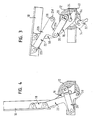
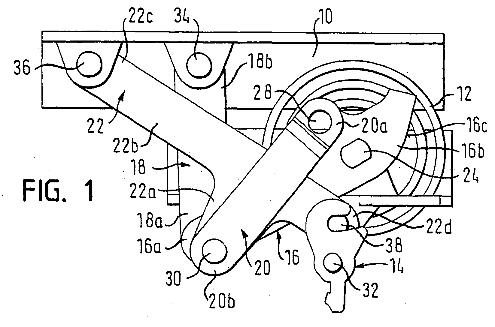
- the hinge mechanism includes in addition to serving as a force storage spring element in Shape of a coil spring 12 and a trigger element in the form of a safety lever 14 a first lever 16, a second lever 18, a third lever 20th and a fourth lever 22 and a first joint 24, a (hidden in Figure 1, however visible in Figure 2) second joint 26, a third joint 28, a fourth Joint 30, a fifth joint 32, a sixth joint 34 and a seventh joint 36th
- the first lever 16 has a first end 16a and a second end 16b a support surface 16c. Between its ends 16a and 16b is the first one Lever 16 rotatably mounted on the vehicle-fixed first hinge 24 and so on the biased coil spring 12 coupled, that he - as shown in Figure 1 - tends to turn in a clockwise direction. At the first end 16a of the first lever 16 is via the second hinge 26, a first end 18 a of the second Levers 18 coupled. The opposite second end 18b of the second lever 18 is coupled via the sixth joint 34 to the hood 10. A first End 20a of the third lever 20 is about that at about the height of the first joint 24 located, in contrast to this but not vehicle-fixed third joint 28th coupled to the first lever 16.
- the fourth lever 22 To the opposite second end 20b of the third lever is about the fourth joint 30, the outer end of the foot section 22a of the T-shaped fourth lever 22 coupled. A first end 22c of the transverse section 22b of the fourth lever 22 is via the seventh hinge 36 to the hood 10 coupled. At the opposite second end 22d of the transverse section 22 b, the fourth lever 22 has a projection 38, on which the safety lever 14 attacks. In the normal position, it holds around the vehicle-fixed fifth joint 32 deflectable safety lever 14, the second end 22 d of the transverse portion 22 b of the fourth lever 22 in the position shown in Figure 1.
- the locking lever 32 When opening the hood 10, the locking lever 32 remains, as in Figure 2, in the same position as in the normal position of the hinge mechanism.
- the first lever 16 is supported by the spring force of Coil spring 12, about the vehicle-fixed first hinge 24 is rotated clockwise, until it with his support surface 16c on a vehicle-fixed contact surface 40 to lie down and rest there.
- the hinge mechanism then takes the in the open position shown in Figure 2, in which the hood 10 against the Is pivoted clockwise.
- the hinge mechanism may be an additional gas spring or the like completely omitted in support of the opening process become.
- the hood 10 In case of imminent accident, the hood 10 from the normal position in the position shown in Figure 3 for the protection of an impacting pedestrian lift, the safety lever 14 via a release mechanism, not shown counterclockwise about the vehicle-fixed fifth joint 32nd deflected so that the projection 38 and thus the second end 22 d of the transverse section 22b of the fourth lever 22 is released.
- the first lever 16 By the force of the spiral spring 12, the first lever 16 is again rotated clockwise until it comes with its support surface 16c on the contact surface 40 comes to rest and there supported. Since the second end 22d of the transverse portion 22b of the fourth lever 22nd is released, the hinge mechanism in the shown in Figure 3 Position converted, in which the hood 10 is a raised, but essentially horizontal position.
- the force of a on the hood 10th bouncing pedestrian can, depending on the design of the coil spring 12 at least partly by itself or by one provided for this purpose be absorbed deformable component.
- the coil spring 12 can again be tense.
- the bonnet becomes 10 counterclockwise in a direction substantially perpendicular to the horizontal Pivoted position so that the hinge mechanism shown in Figure 4 Takes position.
- the hood 10 with its entire weight used as a lever to the first lever 16 counterclockwise rotate and thereby tension the coil spring 12.
- the Safety lever (not shown in Figure 4) for securing the neck 38 and the pivoting back of the hood 10 is the hinge mechanism back in normal position and is ready for another use.
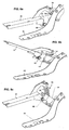
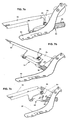
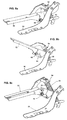
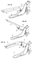
- FIGS. 5a, 5b, 5c to 9a, 9b, 9c show five further embodiments of the hinge mechanism according to the invention, in each case in the normal position (closed engine hood), open position (opened engine hood) and lifting position (pedestrian protection function). All of these embodiments have a base plate 50 which is secured to a fixed body part of the vehicle, and a hood receptacle 52 which is fixedly connected to the hood.
- a shock absorber 54 is provided in each of these embodiments, ie, the force accumulator is designed here as a compression spring 56.
- none of the embodiments is a manual intervention in the hinge mechanism necessary to make it operational again for a lift of the hood.
Landscapes
- Engineering & Computer Science (AREA)
- Mechanical Engineering (AREA)
- Superstructure Of Vehicle (AREA)
Abstract
Ein Scharniermechanismus zum Öffnen einer Motorhaube (10) umfaßt
mehrere Hebel (16, 18, 20, 22). Die Motorhaube (10) kann durch Überführen des
Scharniermechanismus aus einer Normalstellung in eine Öffnungsstellung
geöffnet werden. Der Scharniermechanismus umfaßt ferner einen Kraftspeicher
und ein Auslöseelement. Nach einer Betätigung des Auslöseelements wird der
Scharniermechanismus mit Hilfe des Kraftspeichers aus der Normalstellung
unmittelbar in eine Anhebestellung überführt, in der die Motorhaube (10) eine
angehobene Position zum Schutz eines Fußgängers einnimmt.
Description
Die Erfindung betrifft einen Scharniermechanismus zum Öffnen einer Motorhaube, mit mehreren Hebeln, wobei die Motorhaube durch Überführen des Scharniermechanismus aus einer Normalstellüng in eine Öffnungsstellung geöffnet werden kann.The invention relates to a hinge mechanism for opening a hood, with several levers, the hood by transferring the Hinged mechanism opened from a Normalstellüng in an open position can be.
Um bei einem Kraftfahrzeug mit einem derartigen Scharnier eine zusätzliche Schutzfunktion für Fußgänger zu schaffen, bei der die Motorhaube zur Bereitstellung von zusätzlichem Deformationsraum angehoben wird, mußte bisher das Scharnier entkoppelt und wenigstens ein zusätzliches Gelenk vorgesehen werden. Zudem sind bestimmte Arten von Vorrichtungen zum Anheben der Motorhaube (z.B. pyrotechnische) auch bei einer Fehlauslösung grundsätzlich nur einmal verwendbar, oder sie können nur werkstattseitig mit nicht unerheblichem Aufwand wieder einsatzfähig gemacht werden. Schließlich ist die Funktion solcher sicherheitsrelevanter Vorrichtungen auch bei langem Nichtgebrauch sicherzustellen, was unter Umständen eine regelmäßige Funktionsüberprüfung erfordert.To an additional motor vehicle with such a hinge Provide protection for pedestrians, with the bonnet for deployment has been raised by additional deformation space, so far had the Hinge uncoupled and provided at least one additional joint. In addition, there are certain types of lifting device for the hood (For example, pyrotechnic) even with a false trip basically only once usable, or they can only workshop side with not insignificant effort be made operational again. Finally, the function is such ensure safety-relevant devices even when not in use for a long time, which may require a regular functional check.
Aufgabe der Erfindung ist es, einen mit geringem Aufwand realisierbaren Mechanismus zum Anheben einer Motorhaube zu schaffen, der einfach zu handhaben ist, aber dennoch alle sicherheitsrelevanten Anforderungen erfüllt. The object of the invention is to realize a with little effort Mechanism for lifting a bonnet to create that easy to handle is, but still meets all safety-related requirements.
Zur Lösung dieser Aufgabe wird vorgeschlagen, einen Scharniermechanismus der eingangs genannten Art so weiterzubilden, daß er einen Kraftspeicher und ein Auslöseelement umfaßt, wobei nach einer Betätigung des Auslöseelements der Scharniermechanismus mit Hilfe des Kraftspeichers aus der Normalstellung unmittelbar in eine Anhebestellung überführt wird, in der die Motorhaube eine angehobene Position zum Schutz eines Fußgängers einnimmt. Grundidee der Erfindung ist es, den Fußgänger-Schutzmechanismus in den Scharniermechanismus zum normalen Öffnen der Motorhaube zu integrieren. Die Kraft zum Anheben der Motorhaube liefert der Kraftspeicher, der auch für den normalen Öffnungsvorgang der Haube benutzt werden kann. Durch die besondere Auslegung des Scharniermechanismus kann auf zusätzliche Bauteile größtenteils verzichtet werden. Ein weiterer wesentlicher Vorteil des erfindungsgemäßen Scharniermechanismus besteht darin, daß die bei einem drohenden Unfall erforderlichen Bauteile zum Anheben der Motorhaube bei jedem normalen Öffnen und Schließen der Motorhaube mitbewegt werden, so daß die Gefahr eines Verklemmens oder Festsitzens erheblich verringert ist. Eine Funktionsüberprüfung kann durch Öffnen der Haube auf einfache Weise vorgenommen werden.To solve this problem, it is proposed a hinge mechanism of the aforementioned type so that he has a power storage and a Trigger element comprises, wherein after an actuation of the trigger element of Hinge mechanism with the help of the energy storage from the normal position is transferred directly to a lifting position, in which the hood a raised position to protect a pedestrian occupies. Basic idea of Invention is the pedestrian protection mechanism in the hinge mechanism to integrate for normal opening of the hood. The power to Lifting the hood provides the power storage, which is also for the normal Opening operation of the hood can be used. Due to the special design The hinge mechanism can be largely based on additional components be waived. Another important advantage of the invention Hinge mechanism is that required in the event of an imminent accident Components for lifting the bonnet with each normal opening and Close the hood to be moved, so that the risk of jamming or stuck is significantly reduced. A functional check can be made by opening the hood in a simple manner.
Der Kraftspeicher umfaßt vorzugsweise ein Federelement, insbesondere eine
Spiralfeder oder eine Druckfeder 56, die die notwendige Kraft zum Anheben der
Motorhaube ohne Verzögerung zur Verfügung stellen kann und reversibel einsetzbar
ist.The energy accumulator preferably comprises a spring element, in particular a
Spiral spring or a
Eine Weiterbildung der Erfindung sieht vor, daß der Scharniermechanismus in eine Spannstellung gebracht werden kann, aus der er durch eine Bewegung der Motorhaube unter gleichzeitigem Spannen des Federelements zurück in die Normalstellung gebracht werden kann. Eine solche Ausgestaltung des Scharniermechanismus, die die Reversibilität der Fußgänger-Schutzvorrichtung gewährleistet, erweist sich als besonders vorteilhaft, weil der Scharniermechanismus nach einer möglichen Fehlauslösung ohne besonderen Aufwand vom Fahrer selbst für einen weiteren Einsatz vorbereitet werden kann. A development of the invention provides that the hinge mechanism in a tension position can be brought out of it by a movement of the Hood with simultaneous tensioning of the spring element back into the Normal position can be brought. Such an embodiment of the hinge mechanism, which ensures the reversibility of the pedestrian protection device, proves to be particularly advantageous because the hinge mechanism after a possible false trip without special effort by the driver himself for another task can be prepared.
Gemäß einer bevorzugten Ausführungsform der Erfindung umfaßt der Scharniermechanismus wenigstens vier Hebel und vier Gelenke, wobei
- ein an den Kraftspeicher gekoppelter erster Hebel an einem fahrzeugfesten ersten Gelenk gelagert ist,
- ein an die Motorhaube gekoppelter zweiter Hebel über ein zweites Gelenk an den ersten Hebel gekoppelt ist,
- ein dritter Hebel über ein drittes Gelenk an den ersten Hebel gekoppelt ist, und
- ein ebenfalls an die Motorhaube gekoppelter vierter Hebel über ein viertes Gelenk an den dritten Hebel gekoppelt ist.
- a first lever coupled to the energy accumulator is mounted on a vehicle-fixed first joint,
- a coupled to the hood second lever is coupled via a second joint to the first lever,
- a third lever is coupled to the first lever via a third hinge, and
- a likewise coupled to the hood fourth lever is coupled via a fourth joint to the third lever.
Damit der Scharniermechanismus nach dem "Aufladen" des Kraftspeichers (Spannen der Spiralfeder) unter normalen Umständen in der Normalstellung verharrt und nur in einem Auslösefall aktiviert wird, ist vorgesehen, daß ein am vierten Hebel angeordneter Ansatz in der Normalstellung des Scharniermechanismus durch das Auslöselement in einer fahrzeugfesten Position gehalten und nach Betätigung des Auslöseelements freigegeben wird.So that the hinge mechanism after the "charging" of the energy storage (Tensioning the coil spring) under normal circumstances in the normal position remains active and activated only in a triggering case, it is provided that an am fourth lever arranged approach in the normal position of the hinge mechanism held by the trigger element in a vehicle-fixed position and is released after actuation of the trigger element.
Das Auslöseelement ist vorzugsweise ein um ein fahrzeugfestes fünftes Gelenk umlegbarer Sicherungshebel, der am Ansatz des vierten Hebels angreift.The triggering element is preferably one around a vehicle-fixed fifth Articulated safety lever that engages the neck of the fourth lever.
Alternativ kann der Scharniermechanismus auch als Eingelenker mit zwei Drehpunkten sowie einer an einem Karosserieteil befestigten Grundplatte, einer Haubenaufnahme und einem Schwenkhebel ausgebildet sein.Alternatively, the hinge mechanism can also be used as a single link with two Fulcrums and a base plate attached to a body part, a Hood receptacle and a pivot lever may be formed.
Weitere Merkmale und Vorteile der Erfindung ergeben sich aus der nachfolgenden Beschreibung und aus den beigefügten Zeichnungen, auf die Bezug genommen wird. In den Zeichnungen zeigen:
- Figur 1 eine Seitenansicht eines erfindungsgemäßen Scharniermechanismus in Normalstellung;
- Figur 2 den Scharniermechanismus aus Figur 1 in Öffnungsstellung;
- Figur 3 den Scharniermechanismus aus Figur 1 in Anhebestellung;
- Figur 4 den Scharniermechanismus aus Figur 1 in Spannstellung; und
- Figuren 5a, 5b, 5c bis 9a, 9b, 9c perspektivische Ansichten weiterer Ausführungsformen des erfindungsgemäßen Scharniermechanismus, jeweils in Normalstellung, Öffnungsstellung und Anhebestellung.
- Figure 1 is a side view of a hinge mechanism according to the invention in the normal position;
- Figure 2 shows the hinge mechanism of Figure 1 in the open position;
- Figure 3 shows the hinge mechanism of Figure 1 in Anhebestellung;
- FIG. 4 shows the hinge mechanism from FIG. 1 in the tensioning position; and
- Figures 5a, 5b, 5c to 9a, 9b, 9c are perspective views of further embodiments of the hinge mechanism according to the invention, respectively in the normal position, open position and Anhebestellung.
In Figur 1 ist ein erfindungsgemäßer Scharniermechanismus in Normalstellung,
d.h. bei geschlossener Motorhaube 10 dargestellt. Der Scharniermechanismus
umfaßt neben einem als Kraftspeicher dienenden Federelement in
Form einer Spiralfeder 12 und einem Auslöseelement in Form eines Sicherungshebels
14 einen ersten Hebel 16, einen zweiten Hebel 18, einen dritten Hebel 20
und einen vierten Hebel 22 sowie ein erstes Gelenk 24, ein (in Figur 1 verdecktes,
jedoch in Figur 2 sichtbares) zweites Gelenk 26, ein drittes Gelenk 28, ein viertes
Gelenk 30, ein fünftes Gelenk 32, ein sechstes Gelenk 34 und ein siebtes Gelenk
36.1 shows an inventive hinge mechanism in the normal position,
i.e. shown with the hood closed 10. The hinge mechanism
includes in addition to serving as a force storage spring element in
Shape of a
Der erste Hebel 16 weist ein erstes Ende 16a und ein zweites Ende 16b mit
einer Abstützfläche 16c auf. Zwischen seinen Enden 16a und 16b ist der erste
Hebel 16 an dem fahrzeugfesten ersten Gelenk 24 drehbar gelagert und so an die
vorgespannte Spiralfeder 12 gekoppelt, daß er - gemäß der Darstellung in Figur 1
― dazu tendiert, sich im Uhrzeigersinn zu drehen. An das erste Ende 16a des
ersten Hebels 16 ist über das zweite Gelenk 26 ein erstes Ende 18a des zweiten
Hebels 18 gekoppelt. Das entgegengesetzte zweite Ende 18b des zweiten Hebels
18 ist über das sechste Gelenk 34 an die Motorhaube 10 gekoppelt. Ein erstes
Ende 20a des dritten Hebels 20 ist über das in etwa auf Höhe des ersten Gelenks
24 befindliche, im Gegensatz zu diesem aber nicht fahrzeugfeste dritte Gelenk 28
an den ersten Hebel 16 gekoppelt. An das entgegengesetzte zweite Ende 20b des
dritten Hebels ist über das vierte Gelenk 30 das äußere Ende des Fußabschnitts
22a des T-förmigen vierten Hebels 22 gekoppelt. Ein erstes Ende 22c des Querabschnitts
22b des vierten Hebels 22 ist über das siebte Gelenk 36 an die Motorhaube
10 gekoppelt. Am entgegengesetzten zweiten Ende 22d des Querabschnitts
22b weist der vierte Hebel 22 einen Ansatz 38 auf, an dem der Sicherungshebel 14
angreift. In der Normalstellung hält der um das fahrzeugfeste fünfte Gelenk 32
umlenkbare Sicherungshebel 14 das zweite Ende 22d des Querabschnitts 22b des
vierten Hebels 22 in der in Figur 1 gezeigten Position.The
Beim Öffnen der Motorhaube 10 verbleibt der Sicherungshebel 32, wie in
Figur 2 gezeigt, in der gleichen Position wie in der Normalstellung des Scharniermechanismus.
Der erste Hebel 16 wird, unterstützt durch die Federkraft der
Spiralfeder 12, um das fahrzeugfeste erste Gelenk 24 im Uhrzeigersinn gedreht,
bis er mit seiner Abstützfläche 16c auf einer fahrzeugfesten Anlagefläche 40 zu
liegen kommt und sich dort abstützt. Der Scharniermechanismus nimmt dann die
in Figur 2 gezeigte Öffnungsstellung ein, in der die Motorhaube 10 gegen den
Uhrzeigersinn verschwenkt ist. Je nach Auslegung der Masse der Motorhaube 10
und der Kennlinie der Spiralfeder 12 kann auf eine zusätzliche Gasdruckfeder
oder dergleichen zur Unterstützung des Öffnungsvorgangs ganz verzichtet
werden. Beim Schließen der Motorhaube 10 wird der Scharniermechanismus
wieder in die in Figur 1 gezeigte Stellung überführt.When opening the
Um bei einem drohenden Unfall die Motorhaube 10 aus der Normalstellung in
die in die Figur 3 gezeigte Position zum Schutz eines aufprallenden Fußgängers
anzuheben, wird der Sicherungshebel 14 über einen nicht dargestellten Auslösemechanismus
gegen den Uhrzeigersinn um das fahrzeugfeste fünfte Gelenk 32
umgelenkt, so daß der Ansatz 38 und damit das zweite Ende 22d des Querabschnitts
22b des vierten Hebels 22 freigegeben wird. Durch die Kraft der Spiralfeder
12 wird der erste Hebel 16 wiederum im Uhrzeigersinn gedreht, bis er mit
seiner Abstützfläche 16c auf der Anlagefläche 40 zu liegen kommt und sich dort
abstützt. Da das zweite Ende 22d des Querabschnitts 22b des vierten Hebels 22
freigegeben ist, wird der Scharniermechanismus in die in Figur 3 gezeigte
Stellung überführt, in der die Motorhaube 10 eine angehobene, aber im wesentlichen
waagrechte Position einnimmt. Die Kraft eines auf die Motorhaube 10
prallenden Fußgängers kann je nach Auslegung der Spiralfeder 12 zumindest
teilweise von dieser selbst oder von einem für diesen Zweck vorgesehenen
deformierbaren Bauteil aufgenommen werden.In case of imminent accident, the
Nach dem Anheben der Motorhaube 10 kann die Spiralfeder 12 wieder
gespannt werden. Um die dafür nötige Kraft aufzubringen, wird die Motorhaube
10 gegen den Uhrzeigersinn in eine zur Horizontalen im wesentlichen senkrechte
Position verschwenkt, so daß der Scharniermechanismus die in Figur 4 gezeigte
Stellung einnimmt. So kann die Motorhaube 10 mit ihrer gesamten Gewichtskraft
als Hebel genutzt werden, um den ersten Hebel 16 gegen den Uhrzeigersinn zu
drehen und dadurch die Spiralfeder 12 zu spannen. Nach dem Umlegen des
Sicherungshebels (in Figur 4 nicht dargestellt) zur Sicherung des Ansatzes 38 und
dem Zurückschwenken der Motorhaube 10 befindet sich der Scharniermechanismus
wieder in Normalstellung und steht für einen neuerlichen Einsatz bereit.After lifting the
In den Figuren 5a, 5b, 5c bis 9a, 9b, 9c sind fünf weitere Ausführungsformen
des erfindungsgemäßen Scharniermechanismus dargestellt, jeweils in Normalstellung
(geschlossene Motorhaube), Öffnungsstellung (geöffnete Motorhaube)
und Anhebestellung (Fußgängerschutzfunktion). Alle diese Ausführungsformen
weisen eine Grundplatte 50, die an einem unbeweglichen Karosserieteil des
Fahrzeugs befestigt ist, und eine Haubenaufnahme 52 auf, die fest mit der Motorhaube
verbunden ist. Außerdem ist bei diesen Ausführungsformen jeweils ein
Federbein 54 vorgesehen, d.h. der Kraftspeicher ist hier als Druckfeder 56 ausgeführt.
Bei keiner der Ausführungsformen ist ein manuelles Eingreifen in den
Scharniermechanismus notwendig, um diesen wieder für eine Anhebung der
Motorhaube einsatzfähig zu machen.


Bei den Scharniermechanismen vom Typ Eingelenk sind folgende Merkmale von besonderer Bedeutung für die Funktionalität:
- Der Haltemechanismus (z.B. eine elektromagnetische Vorrichtung) wird bei der Freigabe mitbewegt.
- Die Anordnung des Federbeins 54 kann horizontal oder vertikal sein.
- Beide Lagerpunkte der Druckfeder 56 des
Federbeins 54 können sich mitbewegen. - Der Haltemechanismus für die
Druckfeder 56 kann durch Freigabe eines Drehmoments ermöglicht werden. Die Druckfeder 56 kann zusätzlich ortsfest am Fahrzeug angebunden sein.- Bei den Ausführungsformen der Figuren 5a bis 5c und 6a bis 6c kann die
Druckfeder 56 zusätzlich das Öffnen der Motorhaube 10 unterstützen.
- The holding mechanism (eg an electromagnetic device) is moved during the release.
- The arrangement of the
strut 54 may be horizontal or vertical. - Both bearing points of the
compression spring 56 of thestrut 54 can move with it. - The retaining mechanism for the
compression spring 56 can be enabled by releasing a torque. - The
compression spring 56 may additionally be fixed to the vehicle stationary. - In the embodiments of FIGS. 5 a to 5 c and 6 a to 6 c, the
compression spring 56 can additionally support the opening of theengine hood 10.
Vorteilhaft ist die Bewegung der Gelenke (Drehpunkte) beim normalen
Öffnen der Motorhaube 10, um ein Festsetzen der Gelenke zu vermeiden.Advantageous is the movement of the joints (pivot points) in the normal
Opening the
Claims (8)
Applications Claiming Priority (4)
| Application Number | Priority Date | Filing Date | Title |
|---|---|---|---|
| DE200410004268 DE102004004268A1 (en) | 2004-01-28 | 2004-01-28 | Hinged mechanism for opening an engine bonnet has multiple levers for opening the bonnet by converting the hinged mechanism from a normal/closed to an opened position |
| DE102004004268 | 2004-01-28 | ||
| DE202004017841U | 2004-11-17 | ||
| DE202004017841U DE202004017841U1 (en) | 2004-01-28 | 2004-11-17 | Hood hinge mechanism |
Publications (2)
| Publication Number | Publication Date |
|---|---|
| EP1559858A2 true EP1559858A2 (en) | 2005-08-03 |
| EP1559858A3 EP1559858A3 (en) | 2009-06-03 |
Family
ID=34654997
Family Applications (1)
| Application Number | Title | Priority Date | Filing Date |
|---|---|---|---|
| EP05001203A Withdrawn EP1559858A3 (en) | 2004-01-28 | 2005-01-21 | Vehicle hood hinge |
Country Status (1)
| Country | Link |
|---|---|
| EP (1) | EP1559858A3 (en) |
Cited By (1)
| Publication number | Priority date | Publication date | Assignee | Title |
|---|---|---|---|---|
| EP1752344A1 (en) * | 2005-08-10 | 2007-02-14 | Bayerische Motoren Werke Aktiengesellschaft | Front bonnet hinge with passive deformation element |
Family Cites Families (4)
| Publication number | Priority date | Publication date | Assignee | Title |
|---|---|---|---|---|
| DE4240790C1 (en) * | 1992-12-04 | 1994-02-24 | Daimler Benz Ag | Upwards-moving car-bonnet hinge - has control lever attached to bonnet and with elongated hole for pivot bolt and working in fixed guide on bodywork |
| DE50001215D1 (en) * | 1999-05-17 | 2003-03-13 | Edscha Ag | FRONTHAUHBENANORDNUNG |
| DE19957871A1 (en) * | 1999-12-01 | 2001-06-07 | Volkswagen Ag | Safety arrangement on a vehicle to protect pedestrians |
| DE10136901A1 (en) * | 2001-07-28 | 2003-02-06 | Opel Adam Ag | Bodywork with yielding bonnet (hood) has pivot mounted on cantilever which tilts inward under frontal impact |
-
2005
- 2005-01-21 EP EP05001203A patent/EP1559858A3/en not_active Withdrawn
Cited By (1)
| Publication number | Priority date | Publication date | Assignee | Title |
|---|---|---|---|---|
| EP1752344A1 (en) * | 2005-08-10 | 2007-02-14 | Bayerische Motoren Werke Aktiengesellschaft | Front bonnet hinge with passive deformation element |
Also Published As
| Publication number | Publication date |
|---|---|
| EP1559858A3 (en) | 2009-06-03 |
Similar Documents
| Publication | Publication Date | Title |
|---|---|---|
| DE10314180B4 (en) | Reversible pedestrian protection actuator | |
| DE102007033325B4 (en) | hinge | |
| DE102016002523B3 (en) | Flap hinge for a front flap of a vehicle with a sliding mounting of a Hubaktuators | |
| DE602005000040T2 (en) | Device for lifting a bonnet with a hook as a locking system | |
| DE102005006580B4 (en) | hinge assembly | |
| DE102011083262B4 (en) | Bonnet joint assembly for vehicle | |
| DE102004062105B4 (en) | Device for protecting persons in a frontal collision with a motor vehicle by actively setting up its front hood | |
| EP2704919B1 (en) | Locking device and vehicle seat | |
| EP1716023A1 (en) | Arrangement of a front hood comprising an adjusting lever on a vehicle | |
| DE102009040413A1 (en) | Safety mechanism for lifting e.g. front flap of outer shell of vehicle during person collision, has hinge for guidance of component, and coupling arranged between upper hinge upper part and lower hinge upper part by connecting device | |
| WO2013020612A1 (en) | Locking device | |
| DE102015007336A1 (en) | Vehicle hinge and method for lifting a vehicle hood in an accident situation | |
| DE102005022924A1 (en) | Hinge especially for front bonnet of private motor vehicle has facility whereby during lifting of bonnet the angle between link section changes in same direction as during normal opening and closing of bonnet | |
| EP1160136B1 (en) | Roll-over protection system for vehicles | |
| DE102007002948A1 (en) | Device for wing deployment | |
| DE202015006895U1 (en) | Adjustable flap hinge | |
| DE102009040410B4 (en) | Hinge and method of operating a hinge | |
| DE10331047A1 (en) | Front bonnet arrangement for motor vehicle, comprises a movement coupling between the hinge and lock, with movement coupling having a pull or push member | |
| DE102009040401B4 (en) | Hinge for a vehicle | |
| DE102005007903A1 (en) | Hinge fitting for front hood of passenger car, has hinge side fixing point that moves on circular path around catch side fixing point, during sudden rising of front hood, and captivation unit determining position of hinge support | |
| DE102007025359A1 (en) | Actuating device for a door lock of a sliding door of a motor vehicle comprises a handle which pivots on a first pivoting axis orthogonal to the sliding movement of a door and a rotating part with catches arranged on the rotating part | |
| EP1559858A2 (en) | Vehicle hood hinge | |
| DE102004004268A1 (en) | Hinged mechanism for opening an engine bonnet has multiple levers for opening the bonnet by converting the hinged mechanism from a normal/closed to an opened position | |
| DE10352275B4 (en) | Device for reversing a sensor hood for accident protection actively set front hood of a motor vehicle | |
| DE102005045354A1 (en) | Motor vehicle body`s movable unit e.g. front hood, closing device, has moving component allowing shifting of closing units relative to attachment of units in case of accidentally-activated movement of component in closed condition of device |
Legal Events
| Date | Code | Title | Description |
|---|---|---|---|
| PUAI | Public reference made under article 153(3) epc to a published international application that has entered the european phase |
Free format text: ORIGINAL CODE: 0009012 |
|
| AK | Designated contracting states |
Kind code of ref document: A2 Designated state(s): AT BE BG CH CY CZ DE DK EE ES FI FR GB GR HU IE IS IT LI LT LU MC NL PL PT RO SE SI SK TR |
|
| AX | Request for extension of the european patent |
Extension state: AL BA HR LV MK YU |
|
| PUAL | Search report despatched |
Free format text: ORIGINAL CODE: 0009013 |
|
| AK | Designated contracting states |
Kind code of ref document: A3 Designated state(s): AT BE BG CH CY CZ DE DK EE ES FI FR GB GR HU IE IS IT LI LT LU MC NL PL PT RO SE SI SK TR |
|
| AX | Request for extension of the european patent |
Extension state: AL BA HR LV MK YU |
|
| AKX | Designation fees paid | ||
| STAA | Information on the status of an ep patent application or granted ep patent |
Free format text: STATUS: THE APPLICATION IS DEEMED TO BE WITHDRAWN |
|
| 18D | Application deemed to be withdrawn |
Effective date: 20091204 |
|
| REG | Reference to a national code |
Ref country code: DE Ref legal event code: 8566 |