EP1559845B1 - Process for manufacturing an insulating mat of mineral fibres and insulating mat - Google Patents
Process for manufacturing an insulating mat of mineral fibres and insulating mat Download PDFInfo
- Publication number
- EP1559845B1 EP1559845B1 EP05001906A EP05001906A EP1559845B1 EP 1559845 B1 EP1559845 B1 EP 1559845B1 EP 05001906 A EP05001906 A EP 05001906A EP 05001906 A EP05001906 A EP 05001906A EP 1559845 B1 EP1559845 B1 EP 1559845B1
- Authority
- EP
- European Patent Office
- Prior art keywords
- web
- mineral fibers
- supporting layer
- woven web
- major surface
- Prior art date
- Legal status (The legal status is an assumption and is not a legal conclusion. Google has not performed a legal analysis and makes no representation as to the accuracy of the status listed.)
- Expired - Lifetime
Links
- 238000000034 method Methods 0.000 title claims description 22
- 238000004519 manufacturing process Methods 0.000 title claims description 19
- 229910052500 inorganic mineral Inorganic materials 0.000 title abstract 2
- 230000008569 process Effects 0.000 title description 4
- 239000011707 mineral Substances 0.000 title 1
- 239000002557 mineral fiber Substances 0.000 claims abstract description 85
- 239000011491 glass wool Substances 0.000 claims abstract description 10
- 239000011490 mineral wool Substances 0.000 claims abstract description 8
- 239000000203 mixture Substances 0.000 claims abstract description 7
- 239000000835 fiber Substances 0.000 claims description 39
- 239000011810 insulating material Substances 0.000 claims description 32
- 239000011230 binding agent Substances 0.000 claims description 28
- 239000002131 composite material Substances 0.000 claims description 10
- -1 polypropylene Polymers 0.000 claims description 7
- 238000003475 lamination Methods 0.000 claims description 6
- 239000000155 melt Substances 0.000 claims description 6
- 239000000126 substance Substances 0.000 claims description 6
- 238000000926 separation method Methods 0.000 claims description 5
- 229910052782 aluminium Inorganic materials 0.000 claims description 4
- XAGFODPZIPBFFR-UHFFFAOYSA-N aluminium Chemical compound [Al] XAGFODPZIPBFFR-UHFFFAOYSA-N 0.000 claims description 4
- 239000004744 fabric Substances 0.000 claims description 3
- OKTJSMMVPCPJKN-UHFFFAOYSA-N Carbon Chemical compound [C] OKTJSMMVPCPJKN-UHFFFAOYSA-N 0.000 claims 2
- 239000004952 Polyamide Substances 0.000 claims 2
- 239000004698 Polyethylene Substances 0.000 claims 2
- 239000004743 Polypropylene Substances 0.000 claims 2
- 239000004411 aluminium Substances 0.000 claims 2
- 239000004760 aramid Substances 0.000 claims 2
- 229920003235 aromatic polyamide Polymers 0.000 claims 2
- 229910052799 carbon Inorganic materials 0.000 claims 2
- 239000011521 glass Substances 0.000 claims 2
- 229920002647 polyamide Polymers 0.000 claims 2
- 229920000573 polyethylene Polymers 0.000 claims 2
- 229920001155 polypropylene Polymers 0.000 claims 2
- KKEYFWRCBNTPAC-UHFFFAOYSA-L terephthalate(2-) Chemical compound [O-]C(=O)C1=CC=C(C([O-])=O)C=C1 KKEYFWRCBNTPAC-UHFFFAOYSA-L 0.000 claims 2
- 239000002759 woven fabric Substances 0.000 claims 2
- 238000005299 abrasion Methods 0.000 claims 1
- 238000009413 insulation Methods 0.000 abstract description 24
- WSFSSNUMVMOOMR-UHFFFAOYSA-N Formaldehyde Chemical compound O=C WSFSSNUMVMOOMR-UHFFFAOYSA-N 0.000 abstract description 6
- 229920001807 Urea-formaldehyde Polymers 0.000 abstract description 3
- ISWSIDIOOBJBQZ-UHFFFAOYSA-N Phenol Chemical compound OC1=CC=CC=C1 ISWSIDIOOBJBQZ-UHFFFAOYSA-N 0.000 abstract description 2
- 239000007767 bonding agent Substances 0.000 abstract 2
- 239000000463 material Substances 0.000 description 13
- 241000446313 Lamella Species 0.000 description 8
- 230000006835 compression Effects 0.000 description 8
- 238000007906 compression Methods 0.000 description 8
- 230000001070 adhesive effect Effects 0.000 description 7
- 239000010408 film Substances 0.000 description 7
- 239000000853 adhesive Substances 0.000 description 6
- 238000005452 bending Methods 0.000 description 6
- 239000004745 nonwoven fabric Substances 0.000 description 5
- 239000004033 plastic Substances 0.000 description 5
- 229920003023 plastic Polymers 0.000 description 5
- 238000010030 laminating Methods 0.000 description 4
- 239000007787 solid Substances 0.000 description 4
- 238000009987 spinning Methods 0.000 description 4
- 239000000654 additive Substances 0.000 description 3
- 230000008901 benefit Effects 0.000 description 3
- 238000005520 cutting process Methods 0.000 description 3
- 239000011888 foil Substances 0.000 description 3
- BPQQTUXANYXVAA-UHFFFAOYSA-N Orthosilicate Chemical compound [O-][Si]([O-])([O-])[O-] BPQQTUXANYXVAA-UHFFFAOYSA-N 0.000 description 2
- 239000012876 carrier material Substances 0.000 description 2
- 230000008859 change Effects 0.000 description 2
- 239000006185 dispersion Substances 0.000 description 2
- 239000000428 dust Substances 0.000 description 2
- 238000000227 grinding Methods 0.000 description 2
- 239000012774 insulation material Substances 0.000 description 2
- 229910052751 metal Inorganic materials 0.000 description 2
- 239000002184 metal Substances 0.000 description 2
- 238000010327 methods by industry Methods 0.000 description 2
- 230000036961 partial effect Effects 0.000 description 2
- 230000002829 reductive effect Effects 0.000 description 2
- 238000004804 winding Methods 0.000 description 2
- 229910000831 Steel Inorganic materials 0.000 description 1
- 230000001133 acceleration Effects 0.000 description 1
- 230000009471 action Effects 0.000 description 1
- 239000002969 artificial stone Substances 0.000 description 1
- 230000009286 beneficial effect Effects 0.000 description 1
- 230000005540 biological transmission Effects 0.000 description 1
- 238000009835 boiling Methods 0.000 description 1
- 229910052810 boron oxide Inorganic materials 0.000 description 1
- 239000004566 building material Substances 0.000 description 1
- 239000007795 chemical reaction product Substances 0.000 description 1
- 239000003795 chemical substances by application Substances 0.000 description 1
- 238000005253 cladding Methods 0.000 description 1
- 238000005056 compaction Methods 0.000 description 1
- 150000001875 compounds Chemical class 0.000 description 1
- 238000010924 continuous production Methods 0.000 description 1
- 239000002826 coolant Substances 0.000 description 1
- 230000007423 decrease Effects 0.000 description 1
- 230000003247 decreasing effect Effects 0.000 description 1
- 230000001419 dependent effect Effects 0.000 description 1
- 238000011143 downstream manufacturing Methods 0.000 description 1
- 230000000694 effects Effects 0.000 description 1
- 238000005516 engineering process Methods 0.000 description 1
- 230000003628 erosive effect Effects 0.000 description 1
- 238000007667 floating Methods 0.000 description 1
- 230000004907 flux Effects 0.000 description 1
- SLGWESQGEUXWJQ-UHFFFAOYSA-N formaldehyde;phenol Chemical compound O=C.OC1=CC=CC=C1 SLGWESQGEUXWJQ-UHFFFAOYSA-N 0.000 description 1
- 239000012634 fragment Substances 0.000 description 1
- 239000003365 glass fiber Substances 0.000 description 1
- 150000004676 glycans Chemical group 0.000 description 1
- 229910052602 gypsum Inorganic materials 0.000 description 1
- 239000010440 gypsum Substances 0.000 description 1
- 238000010438 heat treatment Methods 0.000 description 1
- 238000000265 homogenisation Methods 0.000 description 1
- 238000009434 installation Methods 0.000 description 1
- 238000002955 isolation Methods 0.000 description 1
- 238000005304 joining Methods 0.000 description 1
- 238000003754 machining Methods 0.000 description 1
- 230000008018 melting Effects 0.000 description 1
- 238000002844 melting Methods 0.000 description 1
- 239000002480 mineral oil Substances 0.000 description 1
- 239000004570 mortar (masonry) Substances 0.000 description 1
- 239000003921 oil Substances 0.000 description 1
- MOWNZPNSYMGTMD-UHFFFAOYSA-N oxidoboron Chemical class O=[B] MOWNZPNSYMGTMD-UHFFFAOYSA-N 0.000 description 1
- 230000002093 peripheral effect Effects 0.000 description 1
- 229920001568 phenolic resin Polymers 0.000 description 1
- 239000011505 plaster Substances 0.000 description 1
- 239000002985 plastic film Substances 0.000 description 1
- 229920006255 plastic film Polymers 0.000 description 1
- 229920000058 polyacrylate Polymers 0.000 description 1
- 229920001282 polysaccharide Polymers 0.000 description 1
- 239000005017 polysaccharide Substances 0.000 description 1
- 238000002360 preparation method Methods 0.000 description 1
- 238000007639 printing Methods 0.000 description 1
- 239000000047 product Substances 0.000 description 1
- 230000001681 protective effect Effects 0.000 description 1
- 230000002787 reinforcement Effects 0.000 description 1
- 229920005989 resin Polymers 0.000 description 1
- 239000011347 resin Substances 0.000 description 1
- 238000005096 rolling process Methods 0.000 description 1
- 239000003238 silicate melt Substances 0.000 description 1
- 238000007711 solidification Methods 0.000 description 1
- 230000008023 solidification Effects 0.000 description 1
- 239000010959 steel Substances 0.000 description 1
- 239000004575 stone Substances 0.000 description 1
- 238000003860 storage Methods 0.000 description 1
- 230000003746 surface roughness Effects 0.000 description 1
- 229920001169 thermoplastic Polymers 0.000 description 1
- 229920001187 thermosetting polymer Polymers 0.000 description 1
- 239000004416 thermosoftening plastic Substances 0.000 description 1
- 238000009827 uniform distribution Methods 0.000 description 1
- 238000009423 ventilation Methods 0.000 description 1
- 210000002268 wool Anatomy 0.000 description 1
Images


Classifications
-
- D—TEXTILES; PAPER
- D04—BRAIDING; LACE-MAKING; KNITTING; TRIMMINGS; NON-WOVEN FABRICS
- D04H—MAKING TEXTILE FABRICS, e.g. FROM FIBRES OR FILAMENTARY MATERIAL; FABRICS MADE BY SUCH PROCESSES OR APPARATUS, e.g. FELTS, NON-WOVEN FABRICS; COTTON-WOOL; WADDING ; NON-WOVEN FABRICS FROM STAPLE FIBRES, FILAMENTS OR YARNS, BONDED WITH AT LEAST ONE WEB-LIKE MATERIAL DURING THEIR CONSOLIDATION
- D04H13/00—Other non-woven fabrics
-
- D—TEXTILES; PAPER
- D04—BRAIDING; LACE-MAKING; KNITTING; TRIMMINGS; NON-WOVEN FABRICS
- D04H—MAKING TEXTILE FABRICS, e.g. FROM FIBRES OR FILAMENTARY MATERIAL; FABRICS MADE BY SUCH PROCESSES OR APPARATUS, e.g. FELTS, NON-WOVEN FABRICS; COTTON-WOOL; WADDING ; NON-WOVEN FABRICS FROM STAPLE FIBRES, FILAMENTS OR YARNS, BONDED WITH AT LEAST ONE WEB-LIKE MATERIAL DURING THEIR CONSOLIDATION
- D04H1/00—Non-woven fabrics formed wholly or mainly of staple fibres or like relatively short fibres
- D04H1/40—Non-woven fabrics formed wholly or mainly of staple fibres or like relatively short fibres from fleeces or layers composed of fibres without existing or potential cohesive properties
- D04H1/42—Non-woven fabrics formed wholly or mainly of staple fibres or like relatively short fibres from fleeces or layers composed of fibres without existing or potential cohesive properties characterised by the use of certain kinds of fibres insofar as this use has no preponderant influence on the consolidation of the fleece
- D04H1/4209—Inorganic fibres
- D04H1/4218—Glass fibres
- D04H1/4226—Glass fibres characterised by the apparatus for manufacturing the glass fleece
-
- D—TEXTILES; PAPER
- D04—BRAIDING; LACE-MAKING; KNITTING; TRIMMINGS; NON-WOVEN FABRICS
- D04H—MAKING TEXTILE FABRICS, e.g. FROM FIBRES OR FILAMENTARY MATERIAL; FABRICS MADE BY SUCH PROCESSES OR APPARATUS, e.g. FELTS, NON-WOVEN FABRICS; COTTON-WOOL; WADDING ; NON-WOVEN FABRICS FROM STAPLE FIBRES, FILAMENTS OR YARNS, BONDED WITH AT LEAST ONE WEB-LIKE MATERIAL DURING THEIR CONSOLIDATION
- D04H1/00—Non-woven fabrics formed wholly or mainly of staple fibres or like relatively short fibres
- D04H1/40—Non-woven fabrics formed wholly or mainly of staple fibres or like relatively short fibres from fleeces or layers composed of fibres without existing or potential cohesive properties
- D04H1/58—Non-woven fabrics formed wholly or mainly of staple fibres or like relatively short fibres from fleeces or layers composed of fibres without existing or potential cohesive properties by applying, incorporating or activating chemical or thermoplastic bonding agents, e.g. adhesives
- D04H1/64—Non-woven fabrics formed wholly or mainly of staple fibres or like relatively short fibres from fleeces or layers composed of fibres without existing or potential cohesive properties by applying, incorporating or activating chemical or thermoplastic bonding agents, e.g. adhesives the bonding agent being applied in wet state, e.g. chemical agents in dispersions or solutions
-
- D—TEXTILES; PAPER
- D04—BRAIDING; LACE-MAKING; KNITTING; TRIMMINGS; NON-WOVEN FABRICS
- D04H—MAKING TEXTILE FABRICS, e.g. FROM FIBRES OR FILAMENTARY MATERIAL; FABRICS MADE BY SUCH PROCESSES OR APPARATUS, e.g. FELTS, NON-WOVEN FABRICS; COTTON-WOOL; WADDING ; NON-WOVEN FABRICS FROM STAPLE FIBRES, FILAMENTS OR YARNS, BONDED WITH AT LEAST ONE WEB-LIKE MATERIAL DURING THEIR CONSOLIDATION
- D04H1/00—Non-woven fabrics formed wholly or mainly of staple fibres or like relatively short fibres
- D04H1/70—Non-woven fabrics formed wholly or mainly of staple fibres or like relatively short fibres characterised by the method of forming fleeces or layers, e.g. reorientation of fibres
- D04H1/74—Non-woven fabrics formed wholly or mainly of staple fibres or like relatively short fibres characterised by the method of forming fleeces or layers, e.g. reorientation of fibres the fibres being orientated, e.g. in parallel (anisotropic fleeces)
-
- E—FIXED CONSTRUCTIONS
- E04—BUILDING
- E04B—GENERAL BUILDING CONSTRUCTIONS; WALLS, e.g. PARTITIONS; ROOFS; FLOORS; CEILINGS; INSULATION OR OTHER PROTECTION OF BUILDINGS
- E04B1/00—Constructions in general; Structures which are not restricted either to walls, e.g. partitions, or floors or ceilings or roofs
- E04B1/62—Insulation or other protection; Elements or use of specified material therefor
- E04B1/74—Heat, sound or noise insulation, absorption, or reflection; Other building methods affording favourable thermal or acoustical conditions, e.g. accumulating of heat within walls
- E04B1/76—Heat, sound or noise insulation, absorption, or reflection; Other building methods affording favourable thermal or acoustical conditions, e.g. accumulating of heat within walls specifically with respect to heat only
- E04B1/7654—Heat, sound or noise insulation, absorption, or reflection; Other building methods affording favourable thermal or acoustical conditions, e.g. accumulating of heat within walls specifically with respect to heat only comprising an insulating layer, disposed between two longitudinal supporting elements, e.g. to insulate ceilings
- E04B1/7658—Heat, sound or noise insulation, absorption, or reflection; Other building methods affording favourable thermal or acoustical conditions, e.g. accumulating of heat within walls specifically with respect to heat only comprising an insulating layer, disposed between two longitudinal supporting elements, e.g. to insulate ceilings comprising fiber insulation, e.g. as panels or loose filled fibres
- E04B1/7662—Heat, sound or noise insulation, absorption, or reflection; Other building methods affording favourable thermal or acoustical conditions, e.g. accumulating of heat within walls specifically with respect to heat only comprising an insulating layer, disposed between two longitudinal supporting elements, e.g. to insulate ceilings comprising fiber insulation, e.g. as panels or loose filled fibres comprising fiber blankets or batts
-
- E—FIXED CONSTRUCTIONS
- E04—BUILDING
- E04B—GENERAL BUILDING CONSTRUCTIONS; WALLS, e.g. PARTITIONS; ROOFS; FLOORS; CEILINGS; INSULATION OR OTHER PROTECTION OF BUILDINGS
- E04B9/00—Ceilings; Construction of ceilings, e.g. false ceilings; Ceiling construction with regard to insulation
- E04B9/04—Ceilings; Construction of ceilings, e.g. false ceilings; Ceiling construction with regard to insulation comprising slabs, panels, sheets or the like
- E04B9/045—Ceilings; Construction of ceilings, e.g. false ceilings; Ceiling construction with regard to insulation comprising slabs, panels, sheets or the like being laminated
-
- E—FIXED CONSTRUCTIONS
- E04—BUILDING
- E04B—GENERAL BUILDING CONSTRUCTIONS; WALLS, e.g. PARTITIONS; ROOFS; FLOORS; CEILINGS; INSULATION OR OTHER PROTECTION OF BUILDINGS
- E04B1/00—Constructions in general; Structures which are not restricted either to walls, e.g. partitions, or floors or ceilings or roofs
- E04B1/62—Insulation or other protection; Elements or use of specified material therefor
- E04B1/74—Heat, sound or noise insulation, absorption, or reflection; Other building methods affording favourable thermal or acoustical conditions, e.g. accumulating of heat within walls
- E04B1/76—Heat, sound or noise insulation, absorption, or reflection; Other building methods affording favourable thermal or acoustical conditions, e.g. accumulating of heat within walls specifically with respect to heat only
- E04B2001/7683—Fibrous blankets or panels characterised by the orientation of the fibres
Definitions
- the invention relates to a method for producing an insulating element made of binders bound mineral fibers, in particular rockwool and / or glass wool, wherein the mineral fibers are produced from a melt and deposited on a conveyor as a primary web, the primary web stabilized perpendicular to its longitudinal extent and as a secondary web with a core region having a course of mineral fibers substantially perpendicular or steep to the large surfaces, and at least one edge zone with a course of Mineralfasem substantially parallel to the large surfaces deposited on a second conveyor and fed to a curing oven for curing of the binder and subsequently dividing the secondary nonwoven by a separating cut parallel to the large surfaces of the secondary nonwoven into at least two insulating material webs and applying a carrier layer to at least one large surface becomes.
- the invention further relates to an insulation web made of mineral fibers bound with a binder, in particular of mineral wool and / or glass wool, prepared by the process consisting of a large surface having secondary nonwoven with a core region of a course of mineral fibers substantially at right angles or steeply to the large Having surfaces, with a large surface area and a resulting in dividing a secondary nonwoven web in two insulating material separating surface, wherein the Mineralfasem in the region of the separation surface perpendicular to the separation surface and in the region of the surface at an angle deviating from 90 ° to the large surface, in particular parallel to the large surface are arranged running, and with a lamination
- Insulating materials made of vitreous solidified mineral fibers are classified according to the chemical composition commercially available in glass wool and rock wool insulation materials. Both varieties differ in the chemical composition of the mineral fibers.
- the glass wool fibers are made from silicate melts that contain high levels of alkalis and boron oxides that act as fluxes. These melts have a wide processing range can be and with the help of rotating bowls whose walls have holes, take off to relatively smooth and long Mineralfasem, which are usually at least partially bound with mixtures of thermosetting phenol-formaldehyde and urea resins.
- the proportion of these binders in the glass wool insulating materials is for example about 5 to about 10% by mass and is also limited by the fact that the character of a non-combustible insulating material is to be preserved.
- the bond can also be made with thermoplastic binders such as polyacrylates.
- the pulp is added to other substances such as oils in amounts below about 0.4% by mass for hydrophobing and dust binding.
- the impregnated with binders and other additives mineral fibers are collected as fiber web on a slow-speed conveyor. In most cases, the mineral fibers of several fiberizing devices are deposited one after the other on this conveyor. The mineral fibers are oriented largely directionless in one plane. But they store very flat on top of each other. By slight vertical pressure, the fiber web is compressed to the desired thickness and the conveying speed of the conveyor simultaneously to the required density and the binder cured in a curing oven by means of hot air, so that the structure of the fiber web is fixed.
- the primary nonwoven consists of relatively coarse fiber flakes, in the core areas of which higher binder concentrations are present, while in the peripheral areas weaker or non-bonded mineral fibers predominate.
- the mineral fibers are aligned in the fiber flakes approximately in the transport direction.
- Stone wool insulation have contents of binders of about 2 to about 4.5% by mass. With this small amount of binders, only part of the mineral fibers are in contact with the binders.
- the binders used are predominantly mixtures of phenol, formaldehyde and urea resins. Some of the resins are already substituted by polysaccharides.
- Inorganic binders are used as for the glass wool insulating materials only for special applications of insulating materials, as they are much more brittle than the largely elastic to plastic plastic reacting organic binder, which meets the desired character of insulating materials from Mineralfasem as elastic-springy building materials.
- the additives used are mostly high-boiling mineral oils in proportions of 0.2% by mass, in exceptional cases also about 0.4% by mass.
- the primary nonwovens are deposited by means of a pendulum-suspended conveyor transversely across another conveyor, which allows the production of an endless fibrous web consisting of a plurality of obliquely superimposed individual layers.
- a pendulum-suspended conveyor transversely across another conveyor, which allows the production of an endless fibrous web consisting of a plurality of obliquely superimposed individual layers.
- the forces acting on the fiber web cause binder-rich core zones are compacted and unfolded into narrow lamellae, resulting in main folds with folds in flanks.
- the less bound or binder-free mineral fibers in the interstices of the folds and between the lamellae are slightly rolled and slightly compressed.
- the fine structure thus consists of relatively stiff slats, which have a certain flexibility due to their numerous folds, but are relatively stiff parallel to the folding axes and form spaces which are easily compressible.
- the compressive strength and the transverse tensile strength of the fibrous web clearly increase in comparison with a normal, in particular extremely flat, arrangement of the mineral fibers.
- the flexural strength of the fibrous web or of the sections separated from it in the form of plates or Dämmfilzen is therefore significantly higher in the transverse direction than in the production direction.
- the bending strength in the transverse direction on the order of three to four times as high as the bending strength in the production direction.
- Lamellae are usually 50 mm to 200 mm wide and 10 mm to 140 mm thick insulating material elements that are cut off in the direction of production by an at least correspondingly thick fiber web.
- the mineral fibers in the fiber web or in the particularly solid lamellae are oriented at right angles to the cut surfaces, which are now the large surfaces of the lamellae.
- Slats with densities of more than about 75 kg / m 3 are therefore suitable as tensile and pressure resistant insulating layer on the outer walls of buildings and can be glued on the outer wall and then plastered with a reinforced plaster layer.
- Such insulation is referred to as a thermal insulation composite system.
- the pressure-resistant lamella is sufficiently flexible in the longitudinal direction so that it can also be glued onto curved components.
- Slat plates in the bulk density range of about 30 to about 100 kg / m 3 , preferably ⁇ 60 kg / m 3 are separated in the desired thickness in the production direction as lamellae of between about 75 to 250 mm thick fiber web lying flat transverse be glued to a closed carrier material.
- the individual slats are pressed together only under slight pressure and usually form no closed insulation layer.
- the specific amounts of, for example, dispersion adhesives are very low.
- process engineering Bonding foils for example, can be even more easily connected to the surface of the lamellae by heating a foil layer, which in many cases is only about 0.03 to 0.06 mm thick.
- slat plates can also be made from glass wool fiber webs with mineral fibers extending at right angles to the large surfaces.
- the smooth Mineralfasem are directed in these lamellae pronounced parallel to each other and very easy to compress against lateral forces, especially since the bulk densities are generally lower than that of the lamella plates made of rock wool insulation materials.
- Lamellae can also be used to produce lamellar webs having widths of, for example, 500 mm or 1000 mm, thicknesses of approximately 20 mm to approximately 100 mm and lengths of several meters. Due to the orientation of the Mineralfasem perpendicular to the large surfaces can be flat surfaces, for example, provided by large ventilation ducts with a flat and relatively strong insulation layer.
- the lamella webs are compressible and can therefore in the direction of the width of the slats, i. in the longitudinal direction of the slat webs are easily performed around pipelines with small diameters and there give a uniform sheath. This behavior is favored by the joints between the individual lamellae, since here the transverse stiffening of the insulating material is interrupted.
- the lamellae of the lamellar webs are arranged on a carrier layer and connected to the carrier layer, in particular adhesively bonded.
- a carrier layer in particular metal, metal-plastic composite or metal-paper-plastic composite films are used, which may be supplemented by mesh scrims of different types of fibers.
- the slat webs that can be produced from individual slats are limited in terms of their material thickness by the weight of the slats and, among other things, by the weight of the slats, limited adhesive strength on the carrier layer and by the maximum material thickness of the secondary web.
- the lamellae are disc-wise of a mineral fiber web prepared in the usual way, in particular separated a secondary non-woven and adhered with one of the two cut surfaces on the support layer, so that the lamellae and thus the lamellae have a course of the individual Mineralfasem exactly right angles or at steep angles to the cut surfaces of the lamellae and thus the large surfaces of the lamella web.
- the lamellae Depending on the bulk density and the binder contents, the lamellae have a comparatively high transverse tensile strength and at the same time a high compressive strength, so that the lamellae are compressible and in particular compressible in the longitudinal direction of the lamella web.
- Laminated sheets with gross densities of up to approx. 60 kg / m 3 are therefore also used to insulate round components such as pipes, containers and other shaped surfaces. Due to their sufficiently high compressive strength, even roundness or flatness, lamellar sheets can also wear clothing, for example made of thin sheets, free of thermal bridges, without further support structures.
- the mineral fibers oriented at right angles or radially in the case of pipes to the insulated surfaces lead to an increase in the thermal conductivity of the insulating materials compared with insulating materials which have a laminar fiber structure or against pipe shells in which the mineral fibers are arranged concentrically around the central axis of the pipeline.
- lamellae The production of lamellae is complicated in terms of process engineering and leads to a low throughput speed of the production plants.
- the bonding technique is also substantially unsuitable for the partly heavy weight slats.
- An adhesive bond between adjacent lamellae can also be weakened by loose mineral fibers or mineral fiber fragments (dust) being present in the region of the adhesive surfaces.
- Laminated lanes are rolled up tightly for storage and transport and wrapped in a covering.
- the lamellae are stressed at the beginning and at the end of a role strong on shear. After unrolling these slats fall off easily.
- the lamellae are even thrown off when the lamella web is allowed to unroll itself after removal of the sheaths by the action of the large restoring forces.
- Austrollvorgang the end of the role whipping like a whip through the air, so that already partially detached lamellae are completely replaced by the acceleration or the strong impact of the end on the ground.
- carrier layers which are only partially glued to the lamellae are largely eliminated. These include, for example, mesh fabric made of glass fibers or similar planar structures.
- the lamella plates glued as individual elements have the processing technology advantage that necessary separating cuts can either be performed along the transverse joints between adjacent lamellae or at least serve as an auxiliary line for the guidance of a cutting tool.
- the transverse joints can also be marked as a kink on the carrier layer to adapt by folding the slats, the slats in size with respect to the installation conditions.
- a much more economical method for the production of insulating materials with the characteristic of lamellae, lamellar plates or lamellar sheets orientation of the mineral fibers is in the EP 0 741 827 B1 described.
- a thin primary nonwoven is unfolded by an up and down moving conveyor and placed endlessly and looped on a second conveyor. This creates individual layers which are pressed against each other in the horizontal direction and are compressed differently depending on the desired density of density.
- the primary fleece is guided between two pressure-resistant bands, which initially limit only the height of the primary fleece.
- the mineral fibers are aligned in the arcuately deflected tracks of the primary web parallel to boundary surfaces. To obtain largely flat surfaces, the primary nonwoven can also be actively compressed in the vertical direction.
- This orientation of the mineral fibers in the primary non-woven can be done in a separate device, but is suitably made in conjunction with a curing oven.
- the endless fibrous web between two pressure belts, of which at least one is movable in the vertical direction flows through hot air in the vertical direction.
- the printing tapes have pressure-resistant elements with holes in which surface areas of the fiber web press, whereby the surfaces are profiled. In the two surfaces of the fiber web may lead to a further alignment of the mineral fibers, a further compression compared to the underlying areas and possibly to a slight binder enrichment.
- the fibrous web with the binding and / or impregnating agents contained therein is heated, so that moisture present in the fibrous web is expelled and the binders cure, in which they form connecting films or solids.
- After fixation of the fibrous web by solidification of the binder is shown in longitudinal section a structure in which the mineral fibers are oriented in the core of the primary web predominantly perpendicular to the large surfaces of the endless fiber web.
- the mineral fibers are aligned parallel to the large surfaces. Because of the relatively high stiffness of the core of the primary web, the mineral fibers can also be compressed in a mushroom-like manner with correspondingly large vertical pressures and / or pressed downwards between the zones having mineral fibers running at right angles to the large surfaces. Between the arcuately deflected paths of the primary web generally remain small gussets that occur as different widths and different depths transverse grooves in the two major surfaces of the endless fiber web.
- the higher-density zones with the mineral fibers running at right angles to the large surfaces differ significantly from the intermediate zones with a flat arrangement of the mineral fibers.
- the structure In cross-section, the structure is less uniform than in insulation boards used to make fins. For example, the bending tensile strength is lower because of the inhomogeneity of the structure at a comparable density.
- the EP 0 867 572 A2 further describes an insulating element made of mineral fibers, consisting of a mineral fiber fleece and / or a plurality of interconnected lamellae and at least one applied on a main surface lamination in the form of a film.
- This insulating element thus consists of a thin uniform fiber web of flat superimposed and interconnected individual mineral fibers with a thickness of less than 15 mm and a lamination and several interconnected slats. The lamination can be applied both on the thin fiber web and on the lamellae.
- Strength increase may be in the in the EP 0 741 827 B1 as well as in the DD 248 934 A3 described method that the passing of the curing oven, the topmost, a few microns to millimeters thick zone of the fiber web is more compacted and enriched with binders, as the immediately underlying zones.
- a firmer contact with the lamination can be made, although the decisive for the use of transverse tensile strength of the fiber web is primarily influenced by the lower-lying zones.
- a device and a method for producing an insulating material from a strip-shaped nonwoven material in which the non-woven fibers are provided with a curable binder.
- the strip-shaped nonwoven material is first wave-compacted and then heated to cause the compound of the fibers of the non-woven material.
- the nonwoven material is divided centrally by means of a band saw arranged transversely to a conveying direction, so that two nonwoven strips are formed, each with adjacently arranged, U-shaped fiber arrangements.
- the insulating material can be preferably used for the isolation of pipes and other curved components with almost any diameter.
- the invention has the object of developing a method for producing an insulating element, and an insulating element such that, in a simple and inexpensive manner an insulating element can be manufactured which has improved strength characteristics as well as improved thermal conductivity so that the insulating element can be used both in the field of insulation of building facades as well as in the range of curved surfaces.
- the large surface to be joined to the carrier layer is made flat by removing protrusions and / or unevenness after passing through the curing oven before applying the carrier layer.
- an insulating element according to the invention is provided for solving the problem that a support layer is disposed on a smooth formed large surface of the secondary web and that the support layer is mounted on the large surface.
- insulating elements can be produced, which has a profile of a portion of Mineralfasem parallel to the large surfaces, whereby the heat transfer is reduced by the insulating material in the direction perpendicular to the large surfaces.
- mineral fibers aligned at right angles to these mineral fibers ie mineral fibers oriented in the main direction of the transmission heat losses, increase the thermal conductivity.
- These mineral fibers running at right angles to the large surfaces increase the transverse tensile and compressive strength of the insulating material and reduce the rigidity parallel to the large surfaces.
- the secondary web is machined after passing through the curing oven in the region of its with the support layer, for example, by the surface is abraded to eliminate protrusions and / or bumps.
- the surface is abraded to eliminate protrusions and / or bumps.
- mineral fibers whose orientation is not parallel or perpendicular to the large surface are removed.
- mineral fibers are cut away to a predetermined depth with at least one cut parallel to the large surfaces. Subsequently, a grinding process can be provided, with which the required surface roughness is set.
- the process according to the invention can be carried out immediately after the passage of the curing oven.
- both large surfaces of the secondary nonwoven fabric are processed and provided with a carrier layer before the secondary nonwoven fabric is subsequently divided into sections parallel and perpendicular to the large surfaces.
- the secondary nonwoven fabric can first be divided into sections by cuts made parallel to and at right angles to the large surfaces, in particular with saws or lasers, which sections are subsequently machined and adhesively bonded to carrier layers and then rolled up or stored flat on, for example, pallets.
- the region of the edge zone in which the mineral fibers are arranged flat or running at small angles to the large surface are partially or completely removed.
- the bending ability and compressibility of the secondary web or of the insulating element produced therefrom is increased in its longitudinal axis direction.
- An insulating element produced according to this invention is preferably suitable for insulating smooth curved surfaces, such as, for example, pipelines, due to the fact that, in the region of the large surface opposite the large surface area formed with the carrier layer, generally unclad large surface perpendicularly oriented mineral fibers.
- the compressibility of the insulating element in the region of the large surface with an orientation of the mineral fibers perpendicular to the large surface can be increased according to a further feature of the invention in that the secondary nonwoven or the insulating element is pre-compressed during rolling and thereby elasticized.
- the insulating element according to the invention can be covered with a lining, for example with a cover made of a thin sheet metal, wherein the cladding preferably on the large surfaces with the parallel thereto Mineral fibers is arranged so that the slightly compressible outer edge zone below the support layer can elastically resiliently adapt to the inner surface of the panel.
- the elasticity of the insulating element can be used to isolate for the arrangement of insulating elements in a small distance from each other arranged pipes.
- the elasticity of the insulation elements according to the invention is used in the contact areas.
- in at least one large surface in particular in the surface connected to the carrier layer are preferably introduced prior to winding, in particular at right angles to the longitudinal axis of the secondary web incisions and / or recesses.
- Such trained insulating elements have the advantage that their elasticity is improved, so that they are rollable or windable even with larger material thicknesses and associated greater rigidity. Also, this insulation elements could be used by this design for the insulation of objects with highly curved surfaces.
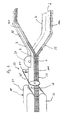
- FIG. 1 shows the first section of a plant 1 for producing a sheet-like insulating element 2 (FIG. 2) from mineral fibers 3.
- the mineral fibers 3 are produced from a silicate material, for example natural and / or artificial stones, by melting the silicate material in a cupola 4 and the melt 5 is fed to a fiberizing unit 6.
- the fiberizing unit 6 has a plurality of spinning wheels 7 driven in rotation, of which only one spinning wheel 7 is shown in FIG.
- the cupola 4 has on the output side a spout 8, via which the melt 5 flows from the cupola 4 onto the spinning wheels 7.
- the mineral fibers 3 are formed from the melt 5 and collected on a first conveyor belt 9.
- a primary nonwoven fabric 10 is formed in which the mineral fibers 3, which are mixed with binder in the fiberising aggregate 6, are aligned in substantially the same direction and arranged in a laminar manner.
- the primary nonwoven 10 is then transferred to a downstream processing station 12 via a second conveyor belt 11 which, in contrast to the first conveyor belt 9, is not a collecting conveyor belt but a transport conveyor belt.
- the general transport direction of the primary web 10 is changed. This change takes place from the original longitudinal direction into a transport in the original transverse direction of the primary web 10.
- the conveying direction is shown in FIG. 1 by an arrow 13.
- the primary web 10 is transported over a roller 14 whose purpose is to change the transport direction of the primary web 10 from a substantially horizontal direction in a substantially vertical direction to supply the primary web 10 to another processing station 15.
- This further processing station 15 has two parallel conveyor belts 16, 17 on, between which the primary web 10 is guided.
- the conveyor belts 16, 17 are arranged to oscillate and oscillate the primary web 10 at right angles to its longitudinal extent as a secondary web 18 on a further conveyor, not shown, which runs parallel to the conveyor belts 9 and 11.
- the thus suspended secondary web 18 is then fed to a compression station 19, in which the secondary web 18 is compressed.
- the compacting station 19 has an upper conveyor belt 20 and a lower conveyor belt 21, between which the secondary web 18 runs.
- the two conveyor belts 20 and 21 of the compression station 19 are arranged in a pendulous manner and, in addition to the function of compacting the secondary web 18, also function to lecturpreln the compacted secondary web 18 in the longitudinal direction meandering.
- This floating of the secondary web 18 causes the secondary web 18 in its central region has an orientation of the mineral fibers 3, which is aligned at right angles to the large surfaces 22, 23.
- the secondary web 18 has an orientation of the mineral fibers 3 which are at an angle other than the orthogonal to the large surfaces 22, 23 to a parallel orientation relative to these large surfaces 22, 23 varies. This arrangement and orientation of the mineral fibers 3 in the secondary web 18 results from the swaying of the secondary web 18 following the compression station 19.
- the suspended secondary web 18 is fed immediately after the swaying of a processing station 24, which has an upper conveyor belt 25 and a lower conveyor belt 26 and their conveying speeds compared to the conveying speed of the compression station 19 is lower, so that the suspended Sekundärvlies 18 compressed in its longitudinal direction and the individual meander of the suspended Sekundärvlieses 18 are pushed together.
- the processing station 24 is followed by a further processing station 27, which also has an upper conveyor belt 28 and a lower conveyor belt 29, between which the suspended secondary web 18 is conveyed.
- the processing station 27 has a further reduced conveying speed of the secondary web 18 in order to continue the compaction and the homogenization of the suspended secondary web 18.
- the thus prepared secondary web 18 forms an end product that can be further processed to form certain insulating elements 2 of mineral fibers 3, such as insulation boards or insulation panels, as will be described below with reference to Figure 2.
- the meandering unfolded and compressed secondary web 18 is fed to a curing oven 30 by two parallel conveyor belts 31 and 32 are arranged.
- hot air is conveyed through the conveyor belts 31, 32 and thus also through the secondary web 18, which hot air cures the binder contained in the secondary web 18 for connecting the individual mineral fibers 3.
- the secondary nonwoven 18 is fixed in its geometric shape, which it obtained in front of the curing oven through the processing stations 12, 15, 19 and 24 and 27.
- the secondary web 18 is compressed between the conveyor belts 31, 32 of the curing oven 30.
- the distance between the two conveyor belts 31, 32 in the curing oven 30 is set to the material thickness of the secondary web 18 and limited by the conveying speed of the conveyor belts 31, 32 in relation to the amount of hot air required to cure the binder.
- the secondary web 18 passes through a first sawing station 33, which has a band saw 34 with a band-shaped saw blade 35, with which saw blade 35 divides the secondary web 18 by a separating cut parallel to the large surfaces 22, 23 into two insulating elements 2 each having a large surface 22, 23 and a substantially coextensive, the respective large surface 22, 23 opposite separating surface.
- the secondary web 18 having a width of 2,400 mm is subsequently subdivided into four part webs by a circular saw with a circular saw blade 37 in the longitudinal direction, each sub web ultimately forming an insulating element 2 and having a width of 1,200 m.
- the insulation elements 22 separated in the longitudinal direction by the separating cut parallel to the large surfaces 22, 23 of the secondary nonwoven 18 are lifted apart and fed to a laminating station, in which a carrier layer 39 is applied to a large surface 22, 23 separating surfaces of the insulating elements 2.
- the carrier layers 39 are hereby stored for each insulating material web 2 in each case a laminating roll, wherein the carrier layers 39 withdrawn with the promotion of the insulating elements 2 of the Kasch michsrolle and the same surface is glued to the insulating elements 2.
- the insulating elements 2 are wound up and packed.
- the insulation elements 2 are cut to length in a predetermined length of the secondary web 18 by a section perpendicular to the longitudinal direction of the secondary web 18.
- the carrier layer 39 is formed as an aluminum-polyethylene composite film and forms an outer reinforcement, protective and / or decorative layer.
- the connection of the support layer 39 with the insulating element 2 in the laminating station is effected by a sprayed onto the insulating element 2 highly viscous dispersion adhesive which is sprayed over the entire surface, selectively or in strips depending on the required connection between the support layer 39 and the insulating element 2 and its adhesive effect.
- the carrier layer 39 is arranged on the large surface 22, 23 of the insulating element 2, in the region of which the mineral fibers 3 are arranged parallel to the large surface 22, 23.
- the insulation elements 2 according to FIG. 4 can be produced from a secondary nonwoven 18 according to FIG. 3, or the secondary nonwoven 18 can have an exclusively orthogonal course of the mineral fibers 2 to the large surfaces 22, 23 before the secondary nonwoven 18 is connected to the carrier layer 39.
- the insulating elements 2 according to FIG. 4 are thus characterized in that the edge zones 101 in the area of the large surfaces 22, 23 have been partially removed and that the cut surface 115 is designed to achieve a high transverse tensile strength in a core region 109 of the insulating element 1 according to FIG.
- the insulating elements 2 may be formed as insulating panels and produced in many different dimensions depending on the width of the production facilities.
- the insulating material elements 2 shown in Figure 4 are formed web-shaped, wherein the carrier layer 39 is disposed on a smooth-formed large surface 22, 23.
- the carrier layer 39 is arranged on the large surface 22, 23 in the region of the edge zone 101, which edge zone the mineral fibers 3 are arranged to extend substantially parallel to the large surface 22, 23.
- connection between the carrier layer 39 and the edge zone 101 takes place in the case of a carrier layer 39 made of an aluminum-polyethylene composite film in that the aluminum-polyethylene composite film is heated, so that the plastic content in the composite film softens and with the large surface 22, 23 bonded in the region of the edge zone 101.
- the insulating elements 2 according to Figure 4 are formed from a secondary web 18 by a division of the secondary web 18 according to the above description, wherein in the secondary web, the primary web 10 is arranged meandering. In the deflection areas between the meanders arise gussets, in which mineral fibers 3 are displaced.
- edge zone 101 can be removed starting from the large surface 22, 23 in different material thickness.
- material thickness of the edge zone is influenced in order to adapt the insulating element 2 to the application.
Landscapes
- Engineering & Computer Science (AREA)
- Textile Engineering (AREA)
- Architecture (AREA)
- Physics & Mathematics (AREA)
- Chemical & Material Sciences (AREA)
- Inorganic Chemistry (AREA)
- Electromagnetism (AREA)
- Civil Engineering (AREA)
- Structural Engineering (AREA)
- Acoustics & Sound (AREA)
- Manufacturing & Machinery (AREA)
- Chemical Kinetics & Catalysis (AREA)
- Dispersion Chemistry (AREA)
- General Chemical & Material Sciences (AREA)
- Laminated Bodies (AREA)
- Nonwoven Fabrics (AREA)
- Formation Of Insulating Films (AREA)
- Inorganic Insulating Materials (AREA)
- Thermistors And Varistors (AREA)
- Glass Compositions (AREA)
Abstract
Description
Die Erfindung betrifft ein Verfahren zur Herstellung eines Dämmstoffelementes aus mit Bindemitteln gebundenen Mineralfasern, insbesondere aus Steinwolle und/oder Glaswolle, bei dem die Mineralfasem aus einer Schmelze hergestellt und auf einer Fördereinrichtung als Primärvlies abgelegt werden, das Primärvlies rechtwinklig zu seiner Längserstreckung aufgependelt und als Sekundärvlies mit einem Kernbereich, der einen Verlauf der Mineralfasem im wesentlichen rechtwinklig oder steil zu den großen Oberflächen aufweist, und zumindest einer Randzone mit einem Verlauf der Mineralfasem im wesentlichen parallel zu den großen Oberflächen auf einer zweiten Fördereinrichtung abgelegt und einem Härteofen zur Aushärtung des Bindemittels zugeführt wird und das Sekundärvlies anschließend durch einen Trennschnitt parallel zu den großen Oberflächen des Sekundärvlieses in zumindest zwei Dämmstoffbahnen unterteilt und auf zumindest eine große Oberfläche eine Trägerschicht aufgebracht wird. Die Erfindung betrifft ferner ein Dämmstoffbahn aus mit einem Bindemittel gebundenen Mineralfasern, insbesondere aus Mineralwolle und/oder Glaswolle, hergestellt nach dem Verfahren, bestehend aus einem große Oberflächen aufweisendem Sekundärvlies mit einem Kernbereich, der einen Verlauf der Mineralfasern im wesentlichen rechtwinklig oder steil zu den großen Oberflächen aufweist, mit einer großen Oberfläche und einer beim Aufteilen eines Sekundärvlieses in zwei Dämmstoffbahnen entstehenden Trennfläche, wobei die Mineralfasem im Bereich der Trennfläche rechtwinklig zur Trennfläche und im Bereich der Oberfläche unter einem Winkel abweichend von 90° zur großen Oberfläche, insbesondere parallel zur großen Oberfläche verlaufend angeordnet sind, und mit einer KaschierungThe invention relates to a method for producing an insulating element made of binders bound mineral fibers, in particular rockwool and / or glass wool, wherein the mineral fibers are produced from a melt and deposited on a conveyor as a primary web, the primary web stabilized perpendicular to its longitudinal extent and as a secondary web with a core region having a course of mineral fibers substantially perpendicular or steep to the large surfaces, and at least one edge zone with a course of Mineralfasem substantially parallel to the large surfaces deposited on a second conveyor and fed to a curing oven for curing of the binder and subsequently dividing the secondary nonwoven by a separating cut parallel to the large surfaces of the secondary nonwoven into at least two insulating material webs and applying a carrier layer to at least one large surface becomes. The invention further relates to an insulation web made of mineral fibers bound with a binder, in particular of mineral wool and / or glass wool, prepared by the process consisting of a large surface having secondary nonwoven with a core region of a course of mineral fibers substantially at right angles or steeply to the large Having surfaces, with a large surface area and a resulting in dividing a secondary nonwoven web in two insulating material separating surface, wherein the Mineralfasem in the region of the separation surface perpendicular to the separation surface and in the region of the surface at an angle deviating from 90 ° to the large surface, in particular parallel to the large surface are arranged running, and with a lamination
Dämmstoffe aus glasig erstarrten Mineralfasem werden nach der chemischen Zusammensetzung handelsüblich in Glaswolle- und Steinwolle-Dämmstoffe unterschieden. Beide Varietäten unterscheiden sich durch die chemische Zusammensetzung der Mineralfasern. Die Glaswolle-Fasern werden aus silikatischen Schmelzen hergestellt, die große Anteile an Alkalien und Boroxiden aufweisen, die als Flussmittel wirken. Diese Schmelzen weisen einen breiten Verarbeitungsbereich auf und lassen sich mit Hilfe von rotierenden Schüsseln, deren Wandungen Löcher aufweisen, zu relativ glatten und langen Mineralfasem ausziehen, die zumeist mit Gemischen aus duroplastisch aushärtenden Phenol-Formaldehyd- und Harnstoffharzen zumindest teilweise gebunden werden. Der Anteil dieser Bindemittel in den Glaswolle-Dämmstoffen beträgt beispielsweise ca. 5 bis ca. 10 Masse-% und wird nach oben auch dadurch begrenzt, dass der Charakter eines nichtbrennbaren Dämmstoffs erhalten bleiben soll. Die Bindung kann auch mit thermoplastischen Bindemitteln wie Polyacrylaten erfolgen. Der Fasermasse werden weitere Stoffe, wie beispielsweise Öle in Mengen unter ca. 0,4 Masse-% zur Hydrophobierung und zur Staubbindung hinzugefügt. Die mit Bindemitteln und sonstigen Zusätzen imprägnierten Mineralfasem werden als Faserbahn auf einer langsam laufenden Fördereinrichtung aufgesammelt. Zumeist werden die Mineralfasem mehrerer Zerfaserungsvorrichtungen nacheinander auf dieser Fördereinrichtung abgelegt. Dabei sind die Mineralfasern in einer Ebene weitgehend richtungslos orientiert. Sie lagern aber ausgesprochen flach übereinander. Durch leichten vertikalen Druck wird die Faserbahn auf die gewünschte Dicke und über die Fördergeschwindigkeit der Fördereinrichtung gleichzeitig auf die erforderliche Rohdichte verdichtet und die Bindemittel in einem Härteofen mittels Heißluft ausgehärtet, so dass die Struktur der Faserbahn fixiert wird.Insulating materials made of vitreous solidified mineral fibers are classified according to the chemical composition commercially available in glass wool and rock wool insulation materials. Both varieties differ in the chemical composition of the mineral fibers. The glass wool fibers are made from silicate melts that contain high levels of alkalis and boron oxides that act as fluxes. These melts have a wide processing range can be and with the help of rotating bowls whose walls have holes, take off to relatively smooth and long Mineralfasem, which are usually at least partially bound with mixtures of thermosetting phenol-formaldehyde and urea resins. The proportion of these binders in the glass wool insulating materials is for example about 5 to about 10% by mass and is also limited by the fact that the character of a non-combustible insulating material is to be preserved. The bond can also be made with thermoplastic binders such as polyacrylates. The pulp is added to other substances such as oils in amounts below about 0.4% by mass for hydrophobing and dust binding. The impregnated with binders and other additives mineral fibers are collected as fiber web on a slow-speed conveyor. In most cases, the mineral fibers of several fiberizing devices are deposited one after the other on this conveyor. The mineral fibers are oriented largely directionless in one plane. But they store very flat on top of each other. By slight vertical pressure, the fiber web is compressed to the desired thickness and the conveying speed of the conveyor simultaneously to the required density and the binder cured in a curing oven by means of hot air, so that the structure of the fiber web is fixed.
Bei der Herstellung von Steinwolle-Dämmstoffen werden imprägnierte Mineralfasem als möglichst dünnes und leichtes Mineralfaservlies, einem sogenannten Primärvlies aufgesammelt und mit hoher Geschwindigkeit aus dem Bereich der Zerfaserungsvorrichtung weggeführt, um erforderliche Kühlmittel gering zu halten, die andernfalls im Verlauf des weiteren Herstellungsverfahren mit weiterem Energieaufwand wieder aus der Faserbahn zu entfernen wären. Aus dem Primärvlies wird eine endlose Faserbahn aufgebaut, die eine gleichmäßige Verteilung der Mineralfasem aufweist.In the production of rock wool insulation impregnated Mineralfasem are collected as thin as possible and lightweight mineral fiber fleece, a so-called primary fleece and carried away at high speed from the field of Zerfaserungsvorrichtung to keep required coolant low, which otherwise in the course of further manufacturing process with additional energy would be removed from the fiber web. From the primary nonwoven an endless fiber web is built, which has a uniform distribution of Mineralfasem.
Das Primärvlies besteht aus relativ groben Faserflocken, in deren Kernbereichen auch höhere Bindemittel-Konzentrationen vorliegen, während in den Randbereichen schwächer oder gar nicht gebundene Mineralfasern vorherrschen. Die Mineralfasem sind in den Faserflocken etwa in Transportrichtung ausgerichtet. Steinwolle-Dämmstoffe weisen Gehalte an Bindemitteln von ca. 2 bis ca. 4,5 Masse-% auf. Bei dieser geringen Menge an Bindemitteln ist auch nur ein Teil der Mineralfasem in Kontakt mit den Bindemitteln. Als Bindemittel werden vorwiegend Gemische aus Phenol-, Formaldehyd- und Harnstoffharzen verwendet. Ein Teil der Harze wird auch schon durch Polysacharide substituiert. Anorganische Bindemittel werden wie auch bei den Glaswolle-Dämmstoffen nur für spezielle Anwendungen der Dämmstoffe eingesetzt, da diese deutlich spröder sind, als die weitgehend elastisch bis plastisch reagierenden organischen Bindemittel, was dem angestrebten Charakter der Dämmstoffe aus Mineralfasem als elastisch-fedemde Baustoffe entgegen kommt. Als Zusatzmittel werden zumeist hochsiedende Mineralöle in Anteilen von 0,2 Masse-%, in Ausnahmefällen auch ca. 0,4 Masse-% verwendet.The primary nonwoven consists of relatively coarse fiber flakes, in the core areas of which higher binder concentrations are present, while in the peripheral areas weaker or non-bonded mineral fibers predominate. The mineral fibers are aligned in the fiber flakes approximately in the transport direction. Stone wool insulation have contents of binders of about 2 to about 4.5% by mass. With this small amount of binders, only part of the mineral fibers are in contact with the binders. The binders used are predominantly mixtures of phenol, formaldehyde and urea resins. Some of the resins are already substituted by polysaccharides. Inorganic binders are used as for the glass wool insulating materials only for special applications of insulating materials, as they are much more brittle than the largely elastic to plastic plastic reacting organic binder, which meets the desired character of insulating materials from Mineralfasem as elastic-springy building materials. The additives used are mostly high-boiling mineral oils in proportions of 0.2% by mass, in exceptional cases also about 0.4% by mass.
Üblicherweise werden die Primärvliese mit Hilfe einer pendelnd aufgehängten Fördereinrichtung quer über eine weitere Fördereinrichtung abgelegt, was die Herstellung einer aus einer Vielzahl von schräg aufeinander liegenden Einzellagen bestehenden endlosen Faserbahn ermöglicht. Durch eine horizontal in Förderrichtung gerichtete und eine gleichzeitige vertikale Stauchung kann die Faserbahn mehr oder weniger intensiv aufgefaltet werden. Die Achsen der Hauptfaltungen sind horizontal ausgerichtet und verlaufen somit quer zu der Förderrichtung.Usually, the primary nonwovens are deposited by means of a pendulum-suspended conveyor transversely across another conveyor, which allows the production of an endless fibrous web consisting of a plurality of obliquely superimposed individual layers. By a horizontally directed in the conveying direction and a simultaneous vertical compression, the fiber web can be unfolded more or less intense. The axes of the main folds are aligned horizontally and thus run transversely to the conveying direction.
Die auf die Faserbahn einwirkenden Kräfte führen dazu, dass bindemittelreiche Kernzonen zu schmalen Lamellen verdichtet und aufgefaltet werden, wobei sich Hauptfalten mit Faltungen in Flanken ergeben. Gleichzeitig werden die weniger gebundenen oder bindemittelfreien Mineralfasem in den Zwickeln der Faltungen und zwischen den Lamellen leicht gerollt und dabei leicht komprimiert. Die Feinstruktur besteht somit aus relativ steifen Lamellen, die durch ihre zahlreichen Faltungen eine gewisse Flexibilität aufweisen, aber parallel zu den Faltungsachsen relativ steif sind und Zwischenräume ausbilden, die leicht kompressibel sind. Durch die Auf- und Verfaltungen steigen die Druckfestigkeit und die Querzugfestigkeit der Faserbahn gegenüber einer normalen, insbesondere ausgesprochen flachen Anordnung der Mineralfasem deutlich an. Die Biegefestigkeit der Faserbahn bzw. der von ihr abgetrennten Abschnitte in Form von Platten oder Dämmfilzen ist deshalb in Querrichtung deutlich höher als in Produktionsrichtung. Bei Dachdämmplatten mit Rohdichten von ca. 130 bis 150 kg/m3 ist die Biegefestigkeit in Querrichtung größenordnungsmäßig drei- bis viermal so hoch, wie die Biegefestigkeit in Produktionsrichtung.The forces acting on the fiber web cause binder-rich core zones are compacted and unfolded into narrow lamellae, resulting in main folds with folds in flanks. At the same time, the less bound or binder-free mineral fibers in the interstices of the folds and between the lamellae are slightly rolled and slightly compressed. The fine structure thus consists of relatively stiff slats, which have a certain flexibility due to their numerous folds, but are relatively stiff parallel to the folding axes and form spaces which are easily compressible. As a result of the build-ups and dislocations, the compressive strength and the transverse tensile strength of the fibrous web clearly increase in comparison with a normal, in particular extremely flat, arrangement of the mineral fibers. The flexural strength of the fibrous web or of the sections separated from it in the form of plates or Dämmfilzen is therefore significantly higher in the transverse direction than in the production direction. at Roof insulation panels with densities of about 130 to 150 kg / m 3 , the bending strength in the transverse direction on the order of three to four times as high as the bending strength in the production direction.
Diese Abhängigkeit der mechanischen Eigenschaften von der Orientierung der Mineralfasem in dem Dämmstoff wird zur Herstellung von Lamellen für Lamellenplatten und handelsüblichen Lamellenbahnen genannten Produkten genutzt.This dependence of the mechanical properties of the orientation of the mineral fibers in the insulating material is used for the production of lamellae for lamellar plates and commercially available lamellar sheets called products.
Bei Lamellen handelt es sich um zumeist 50 mm bis 200 mm breite und 10 mm bis 140 mm dicke Dämmstoffelemente, die in Produktionsrichtung von einer zumindest entsprechend dicken Faserbahn abgeschnitten werden. Die Mineralfasern in der Faserbahn bzw. in den besonders festen Lamellen sind hierbei rechtwinklig zu den Schnittflächen, die nunmehr die großen Oberflächen der Lamellen sind, orientiert. Lamellen mit Rohdichten von über ca. 75 kg/m3 sind deshalb als zug- und druckfeste Dämmschicht auf Außenwänden von Gebäuden verwendbar und können auf der Außenwand verklebt und anschließend mit einer bewehrten Putzschicht verputzt werden. Eine derartige Dämmung wird als Wärmedämm-Verbundsystem bezeichnet. Die druckfeste Lamelle ist in Längsrichtung ausreichend biegsam, um auch auf gekrümmte Bauteile aufgeklebt werden zu können. Gleichzeitig ist sie rechtwinklig zu den Seitenflächen noch so kompressibel, dass mit geringem Anpressdruck Abweichungen von der jeweiligen Länge und Breite (Maßtoleranzen) zwischen den einzelnen Lamellen ausgeglichen werden können. Damit lassen sich fugendichte Dämmschichten herstellen. Mehrere Lamellen wer den ferner zu Lamellenplatten oder Lamellenbahnen zusammengesetzt.Lamellae are usually 50 mm to 200 mm wide and 10 mm to 140 mm thick insulating material elements that are cut off in the direction of production by an at least correspondingly thick fiber web. The mineral fibers in the fiber web or in the particularly solid lamellae are oriented at right angles to the cut surfaces, which are now the large surfaces of the lamellae. Slats with densities of more than about 75 kg / m 3 are therefore suitable as tensile and pressure resistant insulating layer on the outer walls of buildings and can be glued on the outer wall and then plastered with a reinforced plaster layer. Such insulation is referred to as a thermal insulation composite system. The pressure-resistant lamella is sufficiently flexible in the longitudinal direction so that it can also be glued onto curved components. At the same time, it is still so compressible at right angles to the side surfaces that deviations from the respective length and width (dimensional tolerances) between the individual lamellas can be compensated with a small contact pressure. This can be used to produce joint-tight insulation layers. Several lamellae who further assembled to slat plates or lamellae.
Lamellenplatten im Rohdichte-Bereich von ca. 30 bis ca. 100 kg/m3, vorzugsweise < 60 kg/m3 werden in gewünschter Materialstärke in Produktionsrichtung als Lamellen von einer zwischen ca. 75 bis 250 mm dicken Fasernbahn abgetrennt, die flach liegend quer auf ein geschlossenes Trägermaterial aufgeklebt werden. Die einzelnen Lamellen werden dabei nur unter leichtem Druck aneinander gedrückt und bilden zumeist keine geschlossene Dämmschicht. Um aus Brandschutzgründen wenig brennbare Substanz in der Lamellenplatte zu haben, sind die spezifischen Mengen an beispielsweise Dispersionsklebern sehr gering. Verfahrenstechnisch noch einfacher lassen sich beispielsweise Verbundfolien mit der Oberfläche der Lamellen durch Erwärmen einer vielfach nur ca. 0,03 bis ca. 0,06 mm dicken Folienschicht verbinden.Slat plates in the bulk density range of about 30 to about 100 kg / m 3 , preferably <60 kg / m 3 are separated in the desired thickness in the production direction as lamellae of between about 75 to 250 mm thick fiber web lying flat transverse be glued to a closed carrier material. The individual slats are pressed together only under slight pressure and usually form no closed insulation layer. In order to have low combustible substance in the lamellar plate for reasons of fire safety, the specific amounts of, for example, dispersion adhesives are very low. process engineering Bonding foils, for example, can be even more easily connected to the surface of the lamellae by heating a foil layer, which in many cases is only about 0.03 to 0.06 mm thick.
Auf die gleiche Art lassen sich Lamellenplatten auch aus Glaswolle-Faserbahnen mit rechtwinklig zu den großen Oberflächen verlaufenden Mineralfasem herstellen. Die glatten Mineralfasem sind in diesen Lamellenplatten ausgesprochen parallel zueinander gerichtet und gegenüber Seitenkräften sehr leicht zu komprimieren, zumal die Rohdichten generell niedriger sind, als die der Lamellenplatten aus Steinwolle-Dämmstoffen.In the same way, slat plates can also be made from glass wool fiber webs with mineral fibers extending at right angles to the large surfaces. The smooth Mineralfasem are directed in these lamellae pronounced parallel to each other and very easy to compress against lateral forces, especially since the bulk densities are generally lower than that of the lamella plates made of rock wool insulation materials.
Aus Lamellen lassen sich ferner Lamellenbahnen herstellen, die Breiten von beispielsweise 500 mm oder 1000 mm, Dicken von ca. 20 mm bis ca. 100 mm sowie Längen von mehreren Metern aufweisen. Aufgrund der Orientierung der Mineralfasem rechtwinklig zu den großen Oberflächen lassen sich ebene Flächen, beispielsweise von großen Lüftungskanälen mit einer ebenen und relativ festen Dämmschicht versehen. Die Lamellenbahnen sind kompressibel ausgebildet und können daher in Richtung der Breite der Lamellen, d.h. in Längsrichtung der Lamellenbahnen ohne Weiteres um Rohrleitungen mit geringen Durchmessern geführt werden und ergeben dort eine gleichmäßige Ummantelung. Begünstigt wird dieses Verhalten durch die Fugen zwischen den einzelnen Lamellen, da hier die Queraussteifung des Dämmstoffs unterbrochen ist. Die Lamellen der Lamellenbahnen werden auf einer Trägerschicht angeordnet und mit der Trägerschicht verbunden, insbesondere verklebt. Als Trägerschicht werden insbesondere Metall-, Metall-Kunststoff-Verbund- oder Metall-Papier-Kunststoff-Verbundfolien verwendet, die ergänzend durch Gittergelege aus verschiedenartigen Fasern bewehrt sein können.Lamellae can also be used to produce lamellar webs having widths of, for example, 500 mm or 1000 mm, thicknesses of approximately 20 mm to approximately 100 mm and lengths of several meters. Due to the orientation of the Mineralfasem perpendicular to the large surfaces can be flat surfaces, for example, provided by large ventilation ducts with a flat and relatively strong insulation layer. The lamella webs are compressible and can therefore in the direction of the width of the slats, i. in the longitudinal direction of the slat webs are easily performed around pipelines with small diameters and there give a uniform sheath. This behavior is favored by the joints between the individual lamellae, since here the transverse stiffening of the insulating material is interrupted. The lamellae of the lamellar webs are arranged on a carrier layer and connected to the carrier layer, in particular adhesively bonded. As a carrier layer in particular metal, metal-plastic composite or metal-paper-plastic composite films are used, which may be supplemented by mesh scrims of different types of fibers.
Die aus einzelnen Lamellen herstellbaren Lamellenbahnen sind hinsichtlich ihrer Materialstärke durch das Gewicht der Lamellen und die unter anderem durch das Gewicht der Lamellen begrenzte Haftfestigkeit auf der Trägerschicht sowie durch die maximale Materialstärke des Sekundärvlieses begrenzt. Die Lamellen werden scheibenweise von einer in üblicher Weise hergestellten Mineralfaserbahn, insbesondere einem Sekundärvlies abgetrennt und mit einer der beiden Schnittflächen auf die Trägerschicht aufgeklebt, so dass die Lamellen und damit die Lamellenbahn einen Verlauf der einzelnen Mineralfasem exakt rechtwinklig oder in steilen Winkeln zu den Schnittflächen der Lamellen und damit den großen Oberflächen der Lamellenbahn aufweisen. In Abhängigkeit von der Rohdichte und den Bindemittelgehalten weisen die Lamellen eine vergleichsweise hohe Querzugfestigkeit und gleichzeitig eine hohe Druckfestigkeit auf, so dass die Lamellen in Längsrichtung der Lamellenbahn kompressibel und insbesondere stauchfähig sind. Lamellenbahnen mit Rohdichten bis ca. 60 kg/m3 werden deshalb auch zur Dämmung von runden Bauteilen wie Rohrleitungen, Behältern und anders geformtem Oberflächen verwendet. Durch ihre ausreichend hohe Druckfestigkeit, gleichmäßige Rundung oder Ebenheit können Lamellenbahnen auch Bekleidungen, beispielsweise aus dünnen Blechen ohne weitere Unterstützungskonstruktionen wärmebrückenfrei tragen.The slat webs that can be produced from individual slats are limited in terms of their material thickness by the weight of the slats and, among other things, by the weight of the slats, limited adhesive strength on the carrier layer and by the maximum material thickness of the secondary web. The lamellae are disc-wise of a mineral fiber web prepared in the usual way, in particular separated a secondary non-woven and adhered with one of the two cut surfaces on the support layer, so that the lamellae and thus the lamellae have a course of the individual Mineralfasem exactly right angles or at steep angles to the cut surfaces of the lamellae and thus the large surfaces of the lamella web. Depending on the bulk density and the binder contents, the lamellae have a comparatively high transverse tensile strength and at the same time a high compressive strength, so that the lamellae are compressible and in particular compressible in the longitudinal direction of the lamella web. Laminated sheets with gross densities of up to approx. 60 kg / m 3 are therefore also used to insulate round components such as pipes, containers and other shaped surfaces. Due to their sufficiently high compressive strength, even roundness or flatness, lamellar sheets can also wear clothing, for example made of thin sheets, free of thermal bridges, without further support structures.
Lamellenbahnen und Lamellenplatten mit einer geringen Breite ermöglichen bei konstanter Krafteinwirkung größere Verformungen als Lamellenbahnen und Lamellenplatten mit größerer Breite. Der mögliche Biegeradius dieser Lamellenbahnen und Lamellenplatten nimmt mit zunehmender Dämmdicke und Rohdichte ab. Die mit kleiner werdendem Biegeradius ansteigende Kompression der inneren Zonen der Lamellenbahn bzw. Lamellenplatte führt zu einer erheblichen Verdichtung, aber auch zur Erhöhung der Druckfestigkeit in diesen Zonen. Lamellenbahnen eignen sich daher ebenso wie feste, aber wesentlich aufwendiger herzustellende Rohrschalen als tragende Schicht für die Ummantelung von Rohrleitungen, beispielsweise mit glatten oder profilierten Blechen aus beispielsweise Stahl, Aluminium, Kunststoff-Folien, Gips- oder Mörtelschichten. Die rechtwinklig oder bei Rohrleitungen radial zu den gedämmten Oberflächen ausgerichteten Mineralfasern führen zu einer Erhöhung der Wärmeleitfähigkeit der Dämmstoffe gegenüber solchen Dämmstoffen, die eine laminare Faserstruktur aufweisen oder gegenüber Rohrschalen, in denen die Mineralfasem konzentrisch um die Mittelachse der Rohrleitung angeordnet sind.Slat trajectories and slat plates with a small width allow for larger deformations at constant force than slat trays and slat plates with larger width. The possible bending radius of these lamellar sheets and lamellar plates decreases with increasing insulation thickness and bulk density. The increasing with decreasing bending radius compression of the inner zones of the lamellae or lamellar plate leads to a considerable compression, but also to increase the compressive strength in these zones. Laminated webs are therefore just like solid, but much more expensive to produce pipe shells as a supporting layer for the sheathing of pipes, for example, with smooth or profiled sheets of steel, aluminum, plastic films, gypsum or mortar layers. The mineral fibers oriented at right angles or radially in the case of pipes to the insulated surfaces lead to an increase in the thermal conductivity of the insulating materials compared with insulating materials which have a laminar fiber structure or against pipe shells in which the mineral fibers are arranged concentrically around the central axis of the pipeline.
Die Herstellung von Lamellen ist verfahrungstechnisch aufwendig und führt zu einer geringen Durchlaufgeschwindigkeit der Produktionsanlagen. Die Verklebungstechnik ist zudem für die teilweise ein hohes Gewicht aufweisenden Lamellen im Wesentlichen ungeeignet. Eine Klebeverbindung zwischen benachbarten Lamellen kann ferner dadurch geschwächt sein, dass im Bereich der Klebeflächen lose Mineralfasern oder Mineralfaserbruchstücke (Staub) vorhanden sind.The production of lamellae is complicated in terms of process engineering and leads to a low throughput speed of the production plants. The bonding technique is also substantially unsuitable for the partly heavy weight slats. An adhesive bond between adjacent lamellae can also be weakened by loose mineral fibers or mineral fiber fragments (dust) being present in the region of the adhesive surfaces.
Lamellenbahnen werden zur Lagerung und zum Transport fest aufgerollt und mit einer Umhüllung umwickelt. Hierbei werden die Lamellen am Anfang und am Ende einer Rolle stark auf Scherung beansprucht. Nach dem Entrollen fallen diese Lamellen leicht ab. Die Lamellen werden sogar abgeschleudert, wenn der Lamellenbahn erlaubt wird, sich nach dem Entfernen der Umhüllungen durch Einwirkung der großen Rückstellkräfte selbständig zu entrollen. Bei diesem unkontrollierten Entrollvorgang wird das Ende der Rolle peitschenartig durch die Luft geschleudert, so dass bereits teilweise abgelöste Lamellen durch die Beschleunigung oder den starken Aufprall des Endes auf den Boden vollständig abgelöst werden.Laminated lanes are rolled up tightly for storage and transport and wrapped in a covering. Here, the lamellae are stressed at the beginning and at the end of a role strong on shear. After unrolling these slats fall off easily. The lamellae are even thrown off when the lamella web is allowed to unroll itself after removal of the sheaths by the action of the large restoring forces. In this uncontrolled Austrollvorgang the end of the role whipping like a whip through the air, so that already partially detached lamellae are completely replaced by the acceleration or the strong impact of the end on the ground.
Weiterhin besteht die Gefahr, dass sich einzelne Lamellen von der Lamellenbahn lösen, wenn die Lamellen versehentlich nach außen geklappt werden. Wegen der von vornherein ungenügenden Festigkeit der Verbindung der Lamellen und den negativen Einwirkungen bei der Handhabung der Lamellenbahnen scheiden Trägerschichten, die nur partiell mit den Lamellen verklebt sind, weitgehend aus. Hierzu gehören beispielsweise Gittergewebe aus Glasfasern oder ähnliche flächige Gebilde.Furthermore, there is a risk that individual lamellae detach from the lamellar web if the lamellae are inadvertently folded outwards. Because of the initially inadequate strength of the connection of the lamellae and the negative effects in the handling of the lamellae webs, carrier layers which are only partially glued to the lamellae are largely eliminated. These include, for example, mesh fabric made of glass fibers or similar planar structures.
Die als einzelne Elemente aufgeklebten Lamellenplatten haben verarbeitungstechnisch den Vorteil, dass notwendige Trennschnitte entweder entlang der Querfugen zwischen benachbarten Lamellen ausgeführt werden können oder diese zumindest als Hilfslinie für die Führung eines Schneidwerkzeugs dienen. Die Querfugen können ferner als Knickstelle auf der Trägerschicht markiert werden, um durch Abklappen der Lamellen die Lamellenplatten hinsichtlich ihrer Größe an die Einbaubedingungen anzupassen.The lamella plates glued as individual elements have the processing technology advantage that necessary separating cuts can either be performed along the transverse joints between adjacent lamellae or at least serve as an auxiliary line for the guidance of a cutting tool. The transverse joints can also be marked as a kink on the carrier layer to adapt by folding the slats, the slats in size with respect to the installation conditions.
Eine wesentlich wirtschaftlichere Methode zur Herstellung von Dämmstoffen mit der für Lamellen, Lamellenplatten oder Lamellenbahnen charakteristischen Orientierung der Mineralfasern ist in der
Diese Ausrichtung der Mineralfasern im Primärvlies kann in einer separaten Vorrichtung erfolgen, wird aber zweckmäßig in Verbindung mit einem Härteofen vorgenommen. Im Härteofen wird die endlose Faserbahn zwischen zwei Druckbändern, von denen mindestens eines in vertikaler Richtung verfahrbar ist, mit Heißluft in vertikaler Richtung durchströmt. Die Druckbänder weisen drucksteife Elemente mit Löchern auf, in die sich Oberflächenbereiche der Faserbahn eindrücken, wodurch die Oberflächen eine Profilierung erhalten. In den beiden Oberflächen der Faserbahn kann es zu einer weiteren Ausrichtung der Mineralfasern, einer weiteren Verdichtung gegenüber den darunter liegenden Bereichen und unter Umständen zu einer leichten Bindemittelanreicherung kommen.This orientation of the mineral fibers in the primary non-woven can be done in a separate device, but is suitably made in conjunction with a curing oven. In the curing oven, the endless fibrous web between two pressure belts, of which at least one is movable in the vertical direction, flows through hot air in the vertical direction. The printing tapes have pressure-resistant elements with holes in which surface areas of the fiber web press, whereby the surfaces are profiled. In the two surfaces of the fiber web may lead to a further alignment of the mineral fibers, a further compression compared to the underlying areas and possibly to a slight binder enrichment.
Mit Hilfe der durch die Heißluft übertragenen Wärmeenergie wird die Faserbahn mit den darin enthaltenen Binde- und/oder Imprägniermitteln erwärmt, so dass in der Faserbahn vorhandene Feuchtigkeit ausgetrieben wird und die Bindemittel aushärten, in dem sie verbindende Filme oder Festkörper bilden. Nach der Fixierung der Faserbahn durch Verfestigung der Bindemittel zeigt sich im Längsschnitt eine Struktur, in der die Mineralfasern im Kern des Primärvlieses überwiegend rechtwinklig zu den großen Oberflächen der endlosen Faserbahn orientiert sind.With the aid of the thermal energy transmitted through the hot air, the fibrous web with the binding and / or impregnating agents contained therein is heated, so that moisture present in the fibrous web is expelled and the binders cure, in which they form connecting films or solids. After fixation of the fibrous web by solidification of the binder is shown in longitudinal section a structure in which the mineral fibers are oriented in the core of the primary web predominantly perpendicular to the large surfaces of the endless fiber web.
In den oberflächennahen Bereichen sind die Mineralfasern parallel zu den großen Oberflächen ausgerichtet. Wegen der relativ großen Steifigkeit des Kerns des Primärvlieses können die Mineralfasem bei entsprechend großen vertikalen Drücken auch pilzartig gestaucht und/oder nach unten hin zwischen die Zonen mit rechtwinklig zu den großen Oberflächen verlaufenden Mineralfasem gedrückt sein. Zwischen den bogenförmig umgelenkten Bahnen des Primärvlieses verbleiben generell kleine Zwickel, die als unterschiedlich breite und unterschiedlich tiefe Querfurchen in den beiden großen Oberflächen der endlosen Faserbahn auftreten.In the near-surface areas, the mineral fibers are aligned parallel to the large surfaces. Because of the relatively high stiffness of the core of the primary web, the mineral fibers can also be compressed in a mushroom-like manner with correspondingly large vertical pressures and / or pressed downwards between the zones having mineral fibers running at right angles to the large surfaces. Between the arcuately deflected paths of the primary web generally remain small gussets that occur as different widths and different depths transverse grooves in the two major surfaces of the endless fiber web.
Im Horizontalschnitt unterscheiden sich die höher verdichteten Zonen mit den rechtwinklig zu den großen Oberflächen verlaufenden Mineralfasern deutlich von den Zwischenzonen mit einer flachen Anordnung der Mineralfasern. Im Querschnitt ist die Struktur weniger gleichmäßig als bei Dämmplatten, die zur Herstellung von Lamellen verwendet werden. So ist beispielsweise die Biegezugfestigkeit wegen der Inhomogenität der Struktur bei vergleichbarer Rohdichte niedriger.In the horizontal section, the higher-density zones with the mineral fibers running at right angles to the large surfaces differ significantly from the intermediate zones with a flat arrangement of the mineral fibers. In cross-section, the structure is less uniform than in insulation boards used to make fins. For example, the bending tensile strength is lower because of the inhomogeneity of the structure at a comparable density.
Aus der
Die
Aus der
Festigkeitssteigemd kann sich bei dem in der
Aus der
Ausgehend von diesem Stand der Technik liegt der Erfindung die Aufgabe zugrunde, ein Verfahren zur Herstellung eines Dämmstoffelementes sowie ein Dämmstoffelement derart weiterzubilden, dass in einfacher und damit kostengünstiger Weise ein Dämmstoffelement herstellbar ist, welches verbesserte Festigkeitseigenschaften bei gleichzeitig verbesserter Wärmeleitfähigkeit aufweist, so dass das Dämmstoffelement sowohl im Bereich der Dämmung von Gebäudefassaden als auch im Bereich von gekrümmten Oberflächen einsetzbar ist.Starting from this prior art, the invention has the object of developing a method for producing an insulating element, and an insulating element such that, in a simple and inexpensive manner an insulating element can be manufactured which has improved strength characteristics as well as improved thermal conductivity so that the insulating element can be used both in the field of insulation of building facades as well as in the range of curved surfaces.
Zur Lösung dieser Aufgabenstellung ist bei einem erfindungsgemäßen Verfahren vorgesehen, dass die mit der Trägerschicht zu verbindende große Oberfläche nach dem Durchlaufen des Härteofens vor dem Aufbringen der Trägerschicht durch Entfernen von Vorsprüngen und/oder Unebenheiten eben ausgebildet wird. Seitens einer erfindungsgemäßen Dämmstoffelementes ist zur Lösung der Aufgabenstellung vorgesehen, dass eine Trägerschicht auf einer glatt ausgebildeten großen Oberfläche des Sekundärvlieses angeordnet ist und dass die Trägerschicht auf der großen Oberfläche befestigt ist.To solve this problem, it is provided in a method according to the invention that the large surface to be joined to the carrier layer is made flat by removing protrusions and / or unevenness after passing through the curing oven before applying the carrier layer. On the part of an insulating element according to the invention is provided for solving the problem that a support layer is disposed on a smooth formed large surface of the secondary web and that the support layer is mounted on the large surface.
Mit einem erfindungsgemäßen Verfahren können Dämmstoffelemente hergestellt werden, die einen Verlauf eines Teils der Mineralfasem parallel zu den großen Oberflächen aufweist, wodurch der Wärmedurchgang durch den Dämmstoff in Richtung rechtwinklig zu den großen Oberflächen verringert wird. Rechtwinklig zu diesen Mineralfasern, also in Hauptrichtung der Transmissionswärmeverluste ausgerichtete Mineralfasem erhöhen hingegen die Wärmeleitfähigkeit. Diese rechtwinklig zu den großen Oberflächen verlaufenden Mineralfasem erhöhen die Querzug- und Druckfestigkeit des Dämmstoffs und verringern die Steifigkeit parallel zu den großen Oberflächen. Diese von der Orientierung der Mineralfasem abhängigen Eigenschaften lassen sich in einer entsprechend gerichteten Mineralfaserstruktur eines erfindungsgemäßen Dämmstoffelementes kombinieren, wobei sich diese Struktur insbesondere bei einer aufrollbaren Dämmstoffbahn dahingehend als vorteilhaft zeigt, dass die Dämmstoffbahn in einer äußeren, mit der Trägerschicht verbundenen Zone die Struktur und Eigenschaften eines Dämmfilzes aufweist, während die sich an diese Zone anschließenden Bereiche der Dämmstoffbahn bis hin zu einer gegenüberliegend angeordneten und unkaschierte ausgebildeten große Oberfläche durch die Ausrichtung der Mineralfasem rechtwinklig zu den großen Oberflächen die vorteilhaften Eigenschaften von Lamellenbahnen haben.With a method according to the invention insulating elements can be produced, which has a profile of a portion of Mineralfasem parallel to the large surfaces, whereby the heat transfer is reduced by the insulating material in the direction perpendicular to the large surfaces. On the other hand, mineral fibers aligned at right angles to these mineral fibers, ie mineral fibers oriented in the main direction of the transmission heat losses, increase the thermal conductivity. These mineral fibers running at right angles to the large surfaces increase the transverse tensile and compressive strength of the insulating material and reduce the rigidity parallel to the large surfaces. These properties, which are dependent on the orientation of the mineral fibers, can be combined in a suitably oriented mineral fiber structure of an insulating element according to the invention, whereby this structure proves to be advantageous, particularly in the case of a rollable insulation web, in that the insulating web in an outer zone connected to the carrier layer has the structure and properties an insulating felt, while the adjoining this zone areas of the insulating material web to an oppositely arranged and unbacked formed large surface due to the orientation of the mineral fibers perpendicular to the large surfaces have the beneficial properties of lamellar sheets.
Erfindungsgemäß wird das Sekundärvlies nach dem Durchlauf durch den Härteofen im Bereich ihrer mit der Trägerschicht spanabhebend bearbeitet, indem die Oberfläche beispielsweise abgeschliffen wird, um Vorsprünge und/oder Unebenheiten zu beseitigen. Gleichzeitig werden auch Mineralfasem entfernt, deren Ausrichtung nicht parallel oder rechtwinklig zu der großen Oberfläche gegeben ist. Um größere Menge an Mineralfasern zu beseitigen kann alternativ vorgesehen sein, dass Mineralfasern bis zu einer vorgegebenen Tiefe mit zumindest einer Schnitt parallel zu den großen Oberflächen weggeschnitten werden. Im Anschluss kann dann ein Schleifvorgang vorgesehen sein, mit dem die erforderliche Oberflächenrauhigkeit eingestellt wird.According to the invention, the secondary web is machined after passing through the curing oven in the region of its with the support layer, for example, by the surface is abraded to eliminate protrusions and / or bumps. At the same time, mineral fibers whose orientation is not parallel or perpendicular to the large surface are removed. Alternatively, in order to remove larger quantities of mineral fibers it may be provided that mineral fibers are cut away to a predetermined depth with at least one cut parallel to the large surfaces. Subsequently, a grinding process can be provided, with which the required surface roughness is set.
Das erfindungsgemäße Verfahren kann unmittelbar im Anschluss an den Durchlauf des Härteofens durchgeführt werden. In diesem Fall werden beide großen Oberflächen des Sekundärvliese bearbeitet und mit einer Trägerschicht versehen, bevor das Sekundärvlies anschließend parallel und rechtwinklig zu den großen Oberflächen in Abschnitte unterteilt wird.The process according to the invention can be carried out immediately after the passage of the curing oven. In this case, both large surfaces of the secondary nonwoven fabric are processed and provided with a carrier layer before the secondary nonwoven fabric is subsequently divided into sections parallel and perpendicular to the large surfaces.
Bei einer alternativen kontinuierlichen Herstellung kann das Sekundärvlies zuerst durch parallel und rechtwinklig zu den großen Oberflächen insbesondere mit Sägen oder Lasern geführte Schnitte, in Abschnitte aufgeteilt werden, welche Abschnitte nachfolgend spanabhebend bearbeitet und mit Trägerschichten verklebt und anschließend aufgerollt oder flach auf beispielsweise Paletten gelagert werden.In an alternative continuous production, the secondary nonwoven fabric can first be divided into sections by cuts made parallel to and at right angles to the large surfaces, in particular with saws or lasers, which sections are subsequently machined and adhesively bonded to carrier layers and then rolled up or stored flat on, for example, pallets.
Bei der spanabhebenden Bearbeitung werden zumindest durch gelochten Härteofenbänder verursachte Vorsprünge oder Erhebungen entfernt. Hierbei bleiben Kontaktzonen erhalten, in denen die Mineralfasem absolut parallel zu den großen Oberflächen verlaufend angeordnet sind.In machining, protrusions or protuberances caused at least by perforated hardening furnace tapes are removed. This contact zones are maintained in which the mineral fibers are arranged absolutely parallel to the large surfaces running.
Gemäß einer Weiterbildung der Erfindung ist vorgesehen, dass der Bereich der Randzone, in denen die Mineralfasern flach oder in kleinen Winkeln zu der großen Oberfläche verlaufend angeordnet sind, teilweise oder ganz entfernt werden. Hierdurch wird die Biegefähigkeit und Kompressibilität des Sekundärvlieses bzw. des hieraus hergestellten Dämmstoffelementes in seiner Längsachsenrichtung erhöht.According to one embodiment of the invention, it is provided that the region of the edge zone in which the mineral fibers are arranged flat or running at small angles to the large surface, are partially or completely removed. As a result, the bending ability and compressibility of the secondary web or of the insulating element produced therefrom is increased in its longitudinal axis direction.
Mit einem unterschiedlich tiefen Abtrag der Mineralfasem im zur Oberfläche benachbarten Bereich der Randzone werden die Mineralfasem mit einer steileren Ausrichtung zu der großen Oberfläche freigelegt, wodurch sich die Querzugfestigkeit des Sekundärvlieses bzw. des daraus hergestellten Dämmstoffelementes im Bereich der großen Oberfläche vergrößert, so dass auch der Haftverbund zwischen der großen Oberfläche und der darauf angeordneten Trägerschicht wesentlich verbessert wird, Die Trägerschicht wird auf die Oberfläche aufkaschiert.With a different depth of erosion of Mineralfasem in the area adjacent to the surface of the edge zone Mineralfasem be exposed with a steeper orientation to the large surface, whereby the transverse tensile strength of the secondary web or of the insulating material produced therefrom in the area of the large surface increases, so that the Adhesive bond between the large surface and the carrier layer arranged thereon is substantially improved, the carrier layer is laminated to the surface.
Mit der Entfernung der im wesentlichen parallel zur großen Oberfläche ausgerichteten Mineralfasem und einem dadurch erhöhten Anteil an steil bis rechtwinklig zur großen Oberfläche orientierten Mineralfasem steigt der Wärmedurchgang durch das Dämmstoffelement.With the removal of the mineral fibers oriented essentially parallel to the large surface area and thus an increased proportion of mineral fibers oriented steeply to at right angles to the large surface, the heat transfer through the insulating element increases.
Ein nach dieser Erfindung hergestelltes Dämmstoffelement ist aufgrund der im Bereich der, der mit der Trägerschicht ausgebildeten großen Oberfläche gegenüberliegend angeordneten, in der Regel unkaschierten großen Oberfläche rechtwinklig ausgerichteten Mineralfasem bevorzugt zur Dämmung glatter gekrümmter Oberflächen, wie beispielsweise von Rohrleitungen geeignet. Die Kompressibilität des Dämmstoffelementes im Bereich der großen Oberfläche mit einer Ausrichtung der Mineralfasern rechtwinklig zu der großen Oberfläche kann nach einem weiteren Merkmal der Erfindung dadurch erhöht werden, dass das Sekundärvlies bzw. das Dämmstoffelement beim Aufrollen vorkomprimiert und dadurch elastifiziert wird.An insulating element produced according to this invention is preferably suitable for insulating smooth curved surfaces, such as, for example, pipelines, due to the fact that, in the region of the large surface opposite the large surface area formed with the carrier layer, generally unclad large surface perpendicularly oriented mineral fibers. The compressibility of the insulating element in the region of the large surface with an orientation of the mineral fibers perpendicular to the large surface can be increased according to a further feature of the invention in that the secondary nonwoven or the insulating element is pre-compressed during rolling and thereby elasticized.
Das erfindungsgemäße Dämmstoffelement kann mit einer Verkleidung, beispielsweise mit einer Abdeckung aus einem dünnen Blech abgedeckt werden, wobei die Verkleidung bevorzugt auf der großen Oberflächen mit den parallel hierzu verlaufenden Mineralfasem angeordnet wird, so dass sich die leicht kompressible äußere Randzone unterhalb der Trägerschicht elastisch federnd an die Innenfläche der Verkleidung anpassen kann. In gleicher Weise kann die Elastizität des Dämmstoffelementes genutzt werden, um für die Anordnung von Dämmstoffelementen in zu geringem Abstand zueinander angeordnete Rohrleitungen zu isolieren. In diesem Anwendungsfall wird die Elastizität der erfindungsgemäßen Dämmstoffelemente in den Kontaktbereichen genutzt.The insulating element according to the invention can be covered with a lining, for example with a cover made of a thin sheet metal, wherein the cladding preferably on the large surfaces with the parallel thereto Mineral fibers is arranged so that the slightly compressible outer edge zone below the support layer can elastically resiliently adapt to the inner surface of the panel. In the same way, the elasticity of the insulating element can be used to isolate for the arrangement of insulating elements in a small distance from each other arranged pipes. In this application, the elasticity of the insulation elements according to the invention is used in the contact areas.
Nach einem weiteren Merkmal der Erfindung ist vorgesehen, in zumindest eine große Oberfläche, insbesondere in die mit der Trägerschicht verbundene Oberfläche vorzugsweise vor dem Aufwickeln, insbesondere rechtwinklig zur Längsachse des Sekundärvlieses verlaufende Einschnitte und/oder Ausnehmungen eingebracht werden. Derartig ausgebildete Dämmstoffelemente haben den Vorteil, dass ihre Elastizität verbessert ist, so dass sie auch bei größeren Materialstärken und damit verbundener größerer Steifigkeit roll- oder wickelbar sind. Auch könne diese Dämmstoffelemente durch diese Ausgestaltung zur Dämmung von Objekten mit stark gekrümmten Oberflächen verwendet werden.According to a further feature of the invention, it is provided that in at least one large surface, in particular in the surface connected to the carrier layer are preferably introduced prior to winding, in particular at right angles to the longitudinal axis of the secondary web incisions and / or recesses. Such trained insulating elements have the advantage that their elasticity is improved, so that they are rollable or windable even with larger material thicknesses and associated greater rigidity. Also, this insulation elements could be used by this design for the insulation of objects with highly curved surfaces.
Weitere Merkmal und Vorteile der Erfindung ergeben sich aus der nachfolgenden Beschreibung der zugehörigen Zeichnung, in der bevorzugte Ausführungsformen eines Dämmstoffelementes und einer Vorrichtung zur Herstellung eines Dämmstoffelementes dargestellt sind. In der Zeichnung zeigen:
- Figur 1
- einen ersten Abschnitt einer schematisch dargestellten Anlage zur Herstellung eines Dämmstoffelementes aus Mineralfasern;
Figur 2- einen zweiten Abschnitt der Anlage zur Durchführung des Verfahrens zur Herstellung eines Dämmstoffelementes aus Mineralfasem gemäß Figur 1,
Figur 3- einen Abschnitt eines Dämmstoffelementes in verschiedenen Bearbeitungsstufen im Längsschnitt und
- Figur 4
- ein in mehrere Abschnitte unterteiltes Dämmstoffelement in Seitenansicht.
- FIG. 1
- a first portion of a schematically illustrated plant for producing an insulating element made of mineral fibers;
- FIG. 2
- a second section of the plant for carrying out the method for producing a mineral fiber insulating element according to Figure 1,
- FIG. 3
- a section of an insulating element in different processing stages in longitudinal section and
- FIG. 4
- a subdivided into several sections insulation element in side view.
Figur 1 zeigt den ersten Abschnitt einer Anlage 1 zur Herstellung eines bahnenförmigen Dämmstoffelementes 2 (Figur 2) aus Mineralfasem 3. Die Mineralfasem 3 werden aus einem silikatischen Material, beispielsweise natürlichen und/oder künstlichen Steinen hergestellt, indem in einem Kupolofen 4 das silikatische Material geschmolzen und die Schmelze 5 einem Zerfaserungsaggregat 6 zugeführt wird. Das Zerfaserungsaggregat 6 weist mehrere rotierend angetriebene Spinnräder 7 auf, von denen in Figur 1 lediglich ein Spinnrad 7 dargestellt ist.FIG. 1 shows the first section of a plant 1 for producing a sheet-like insulating element 2 (FIG. 2) from
Der Kupolofen 4 weist ausgangsseitig eine Ausgussrinne 8 auf, über die die Schmelze 5 aus dem Kupolofen 4 auf die Spinnräder 7 fließt.The cupola 4 has on the output side a
Durch die rotatorische Bewegung der Spinnräder 7 werden die Mineralfasem 3 aus der Schmelze 5 gebildet und auf einem ersten Förderband 9 gesammelt. Auf diesem ersten Förderband 9 bildet sich ein Primärvlies 10, in dem die mit im Zerfaserungsaggregat 6 mit Bindmitteln versetzten Mineralfasem 3 in im Wesentlichen gleicher Richtung ausgerichtet und laminar angeordnet sind. Das Primärvlies 10 wird sodann über ein zweites Förderband 11, welches im Unterschied zum ersten Förderband 9 kein Sammelförderband, sondern ein Transportförderband ist, einer nachgeschalteten Bearbeitungsstation 12 übergeben.Due to the rotational movement of the
In der Bearbeitungsstation 12 wird die allgemeine Transportrichtung des Primärvlieses 10 geändert. Diese Änderung erfolgt von der ursprünglichen Längsrichtung in einen Transport in die ursprüngliche Querrichtung des Primärvlieses 10. Die Förderrichtung ist in Figur 1 durch einen Pfeil 13 dargestellt.In the
Das Primärvlies 10 wird über eine Walze 14 transportiert, deren Zweck es ist, die Transportrichtung des Primärvlieses 10 aus einer im Wesentlichen horizontalen Richtung in eine im Wesentlichen vertikale Richtung zu ändern, um das Primärvlies 10 einer weiteren Bearbeitungsstation 15 zuzuführen. Diese weitere Bearbeitungsstation 15 weist zwei parallel zueinander verlaufende Förderbänder 16, 17 auf, zwischen denen das Primärvlies 10 geführt ist. Die Förderbänder 16, 17 sind pendelnd angeordnet und pendeln das Primärvlies 10 rechtwinklig zu seiner Längserstreckung als Sekundärvlies 18 auf einer nicht näher dargestellten weiteren Fördereinrichtung auf, welche parallel zu den Förderbändern 9 und 11 verläuft.The
Das derart aufgependelte Sekundärvlies 18 wird sodann einer Verdichtungsstation 19 zugeführt, in welcher das Sekundärvlies 18 komprimiert wird. Die Verdichtungsstation 19 weist ein oberes Förderband 20 und ein unteres Förderband 21 auf, zwischen denen das Sekundärvlies 18 läuft. Die beiden Förderbänder 20 und 21 der Verdichtungsstation 19 sind pendelnd angeordnet und haben neben der Funktion der Verdichtung des Sekundärvlieses 18 auch die Funktion, das verdichtete Sekundärvlies 18 in Längsrichtung mäandrierend aufzupendeln. Dieses Aufpendeln des Sekundärvlieses 18 führt dazu, dass das Sekundärvlies 18 in seinem mittleren Bereich eine Orientierung der Mineralfasern 3 aufweist, die rechtwinklig zu den großen Oberflächen 22, 23 ausgerichtet ist. In Randzonen 101 unmittelbar unterhalb der großen Oberflächen 22, 23 weist das Sekundärvlies 18 eine Orientierung der Mineralfasern 3 auf, die unter einem Winkel abweichend von der Orthogonalen zu den großen Oberflächen 22, 23 bis hin zu einer parallelen Ausrichtung relativ zu diesen großen Oberflächen 22, 23 variiert. Diese Anordnung und Orientierung der Mineralfasern 3 in dem Sekundärvlies 18 resultiert aus dem Aufpendeln des Sekundärvlieses 18 im Anschluss an die Verdichtungsstation 19.The thus suspended
Das aufgependelte Sekundärvlies 18 wird unmittelbar nach dem Aufpendeln einer Bearbeitungsstation 24 zugeführt, die ein oberes Förderband 25 und ein unteres Förderband 26 aufweist und deren Fördergeschwindigkeiten im Vergleich zur Fördergeschwindigkeit der Verdichtungsstation 19 geringer ist, so dass das aufgependelte Sekundärvlies 18 in seiner Längsrichtung komprimiert und die einzelnen Mäander des aufgependelten Sekundärvlieses 18 zusammengeschoben werden.The suspended
Der Bearbeitungsstation 24 ist eine weitere Bearbeitungsstation 27 nachgeschaltet, die ebenfalls ein oberes Förderband 28 und ein unteres Förderband 29 aufweist, zwischen denen das aufgependelte Sekundärvlies 18 gefördert wird. Die Bearbeitungsstation 27 weist eine weitergehend reduzierte Fördergeschwindigkeit des Sekundärvlieses 18 auf, um die Verdichtung und die Homogenisierung des aufgependelten Sekundärvlieses 18 fortzusetzen.The
Das derart vorbereitete Sekundärvlies 18 bildet ein Endprodukt, das zur Bildung von bestimmten Dämmstoffelementen 2 aus Mineralfasern 3, wie zum Beispiel Dämmstoffplatten oder Dämmstoffbahnen weiterverarbeitet werden kann, wie dies nachfolgend in Bezug zu Figur 2 beschrieben wird.The thus prepared
Das mäandrierend aufgefaltete und komprimierte Sekundärvlies 18 wird einem Härteofen 30 zugeführt, indem zwei parallel zueinander verlaufende Förderbänder 31 und 32 angeordnet sind. In dem Härteofen 30 wird Heißluft durch die Förderbänder 31, 32 und somit auch durch das Sekundärvlies 18 gefördert, welche Heißluft das in dem Sekundärvlies 18 zur Verbindung der einzelnen Mineralfasem 3 enthaltene Bindemittel aushärtet. Durch die Aushärtung des Bindemittels wird das Sekundärvlies 18 in seiner geometrischen Form, die es vor dem Härteofen durch die Bearbeitungsstationen 12, 15, 19 und 24 sowie 27 erhalten hat, fixiert. Gleichzeitig wird das Sekundärvlies 18 zwischen den Förderbändern 31, 32 des Härteofens 30 komprimiert.The meandering unfolded and compressed
Der Abstand der beiden Förderbänder 31, 32 im Härteofen 30 ist auf die Materialstärke des Sekundärvlieses 18 eingestellt und durch die Fördergeschwindigkeit der Förderbänder 31, 32 im Verhältnis zur erforderlichen Heißluftmenge, um das Bindemittel auszuhärten, begrenzt.The distance between the two
Im Anschluss an den Härteofen 30 läuft das Sekundärvlies 18 durch eine erste Sägestation 33, die eine Bandsäge 34 mit einem bandförmigen Sägeblatt 35 aufweist, mit welchem Sägeblatt 35 das Sekundärvlies 18 durch einen Trennschnitt parallel zu den großen Oberflächen 22, 23 in zwei Dämmstoffelemente 2 unterteilt wird, die jeweils eine große Oberfläche 22, 23 und eine im Wesentlichen flächengleiche, der jeweiligen großen Oberfläche 22, 23 gegenüberliegende Trennfläche aufweisen.Subsequent to the curing
Das eine Breite von 2.400 mm aufweisende Sekundärvlies 18 wird anschließend durch eine Kreissäge mit einem Kreissägeblatt 37 in Längsrichtung in vier Teilbahnen unterteilt, wobei jede Teilbahn letztendlich ein Dämmstoffelement 2 darstellt und eine Breite von 1.200 m aufweist.The
Die in Längsrichtung durch den Trennschnitt parallel zu den großen Oberflächen 22, 23 des Sekundärvlieses 18 getrennten Dämmstoffelemente 22 werden voneinander abgehoben und einer Kaschierungsstation zugeführt, in der auf eine große Oberfläche 22, 23 Trennflächen der Dämmstoffelemente 2 eine Trägerschicht 39 aufgebracht wird. Die Trägerschichten 39 sind hierbei für jede Dämmstoffbahn 2 in jeweils einer Kaschierungsrolle bevorratet, wobei die Trägerschichten 39 mit der Förderung der Dämmstoffelemente 2 von der Kaschierungsrolle abgezogen und flächengleich mit den Dämmstoffelementen 2 verklebt wird. Im Anschluss an die Kaschierungsstation werden die Dämmstoffelemente 2 aufgewickelt und verpackt. Zu diesem Zweck werden die Dämmstoffelemente 2 in einem vorbestimmten Längenmaß von dem Sekundärvlies 18 durch einen Schnitt rechtwinklig zur Längsrichtung des Sekundärvlieses 18 abgelängt.The
Die Trägerschicht 39 ist als Aluminium-Polyethylen-Verbundfolie ausgebildet und bildet eine äußere Verstärkungs-, Schutz- und/oder Dekorationsschicht. Die Verbindung der Trägerschicht 39 mit dem Dämmstoffelement 2 in der Kaschierungsstation erfolgt durch einen auf das Dämmstoffelement 2 aufgesprühten hochviskosen Dispersionskleber, der in Abhängigkeit der erforderlichen Verbindung zwischen der Trägerschicht 39 und dem Dämmstoffelement 2 sowie seiner Klebewirkung vollflächig, punktuell oder streifenförmig aufgesprüht wird. Die Trägerschicht 39 ist auf der großen Oberfläche 22, 23 des Dämmstoffelementes 2 angeordnet, in deren Bereich die Mineralfasem 3 parallel zu der großen Oberfläche 22, 23 angeordnet sind. Es ist ergänzend vorgesehen, dass vor dem Wickeln des Dämmstoffelements 2 die im Bereich der großen Oberflächen 22, 23 vorhandenen Mineralfasem 3, die von einer rechtwinkligen Orientierung zu den großen Oberflächen 22, 23 abweichen, durch Schneiden oder Schleifen teilweise entfernt werden, wobei auch Vorsprünge aus Mineralfasern 3 oder Unebenheiten in der großen Oberfläche 22, 23 entfernt werden, um eine ebene und glatte Fläche zur Befestigung der Trägerschicht 39 zu schaffen.The
In Figur 3 ist zu erkennen, dass mit den Schneidwerkzeugen 114 entweder ein Teil der Randzonen 101 oder die gesamten Randzonen 101 entfernt werden können, so dass das Sekundärvlies 18 unterschiedliche Faserverläufe aufweisen kann. Insbesondere können aus einem Sekundärvlies 18 gemäß Figur 3 die Dämmstoffelemente 2 gemäß Figur 4 hergestellt werden oder das Sekundärvlies 18 kann einen insgesamt ausschließlich rechtwinkligen Verlauf der Mineralfasem 2 zu den großen Oberflächen 22, 23 aufweisen, bevor das Sekundärvlies 18 mit der Trägerschicht 39 verbunden wird.It can be seen in FIG. 3 that with the
Die Dämmstoffelemente 2 gemäß Figur 4 sind somit dadurch geprägt, dass die Randzonen 101 im Bereich der großen Oberflächen 22, 23 teilweise entfernt worden sind und dass die Schnittfläche 115 zur Erzielung einer hohen Querzugfestigkeit in einem Kernbereich 109 des Dämmstoffelementes 1 gemäß Figur 4 ausgebildet ist.The insulating
Die Dämmstoffelemente 2 können als Dämmstoffplatten ausgebildet sein und in Abhängigkeit von der Breite der Produktionsanlagen in vielen unterschiedlichen Abmessungen hergestellt werden.The insulating
Die in Figur 4 dargestellten Dämmstoffelemente 2 sind bahnenförmig ausgebildet, wobei die Trägerschicht 39 auf einer glatt ausgebildeten großen Oberfläche 22, 23 angeordnet ist. Die Trägerschicht 39 ist auf der großen Oberfläche 22, 23 im Bereich der Randzone 101 angeordnet, welcher Randzone die Mineralfasem 3 im Wesentlichen parallel zur großen Oberfläche 22, 23 verlaufend angeordnet sind.The insulating
Die Verbindung zwischen der Trägerschicht 39 und der Randzone 101 erfolgt im Falle einer Trägerschicht 39 aus einer Aluminium-Polyethylen-Verbundfolie dadurch, dass die Aluminium-Polyethylen-Verbundfolie erwärmt wird, so dass der Kunststoffanteil in der Verbundfolie erweicht und mit der großen Oberfläche 22, 23 im Bereich der Randzone 101 verklebt.The connection between the
Die Dämmstoffelemente 2 gemäß Figur 4 sind aus einem Sekundärvlies 18 durch eine Aufteilung des Sekundärvlieses 18 gemäß voranstehender Beschreibung ausgebildet, wobei in dem Sekundärvlies das Primärvlies 10 mäandrierend angeordnet ist. In den Umlenkungsbereichen zwischen den Mäandern entstehen Zwickel, in welche Mineralfasern 3 verdrängt werden.The insulating
In Figur 4 ist zu erkennen, dass die Randzone 101 in unterschiedlicher Materialstärke von der großen Oberfläche 22, 23 ausgehend entfernt werden kann. Hierdurch wird die Materialstärke der Randzone beeinflusst, um das Dämmstoffelement 2 an die Anwendung anzupassen.It can be seen in FIG. 4 that the
Claims (16)
- Method for producing an insulating element from binder-bound mineral fibers, in particular from rock wool and/or glass wool, wherein the mineral fibers are produced from a melt and are deposited as a primary non-woven web on a conveyor device, wherein the primary non-woven web is arranged by means of pendulums in overlapping folds at right angles to its longitudinal extension and is deposited as a secondary non-woven web having a core area in which the mineral fibers are oriented substantially at right angles or steeply inclined with respect to the major surfaces and having at least one fringe in which the mineral fibers are oriented substantially parallel to the major surfaces on a second conveyor device and are fed to a hardening furnace for the curing of the binder, and wherein the secondary non-woven web is subsequently divided in at least two insulating material webs by a split cut parallel to the major surfaces of the secondary non-woven web, and wherein a supporting layer is applied to at least one major surface,
characterized in
that after passing through the hardening furnace (30) and prior to the applying of the supporting layer (39) the major surface (22, 23) that is to be connected to the supporting layer (39) is made even by removing protrusions and/or irregularities. - Method according to claim 1,
characterized in
that the protrusions and/or irregularities are removed by abrasion and/or by at least one cut parallel to the major surface (22, 23). - Method according to claim 1
characterized in
that the protrusions and/or irregularities together with the mineral fibers (3) are removed up and into a region of the fringe (101) in which the mineral fibers (3) are predominantly, namely at least 80%, oriented parallel to the major surface (22, 23). - Method according to claim 1,
characterized in
that as a supporting layer (39) an air-permeable and/or thermally resistant non-woven web, woven fabric or non crimp fabric, especially from glass and/or natural fibers or organic chemical fibers, like for instance carbon, aramid, terephthalate, polyamide, polypropylene or mixtures thereof, or a film, for example an aluminium polyethylene composite film is applied at least in one layer and especially in the form of webs that are resistant to extension. - Method according to claim 3,
characterized in
that the mineral fibers which in the region of the fringe (101) are not oriented parallel to the major surfaces (22, 23) are displaced to gussets between adjacent meanders (3) of the secondary non-woven web (18). - Method according to claim 1,
characterized in
that the secondary non-woven web (18) which is connected to the supporting layer (18) is wound up. - Method according to claim 1,
characterized in
that the secondary non-woven web (18) which is connected to the supporting layer (18) is compressed in the direction of the surface normal of the major surfaces (22, 23) prior to being wound up. - Method according to claim 1,
characterized in
that the supporting layer (18) is glued to the secondary non-woven web (18). - Method according to claim 1,
characterized in
that preferably prior to the winding-up operation incisions and/or recesses that preferably extend at right angles to the longitudinal axis of the secondary non-woven web (18) are made in at least one major surface (22, 23), especially in that surface (22, 23) which is connected to the supporting layer. - Method according to claim 1,
characterized in
that prior to applying the supporting layer (39) the secondary non-woven web (18) is subdivided in sections in parallel and/or at right angles to its longitudinal direction. - Method according to claim 1,
characterized in
that the mineral fibers (3) of the major surface (22, 23) to be connected to the supporting layer (39) are removed up to the core area (109) after passing through the hardening furnace (30) before applying the supporting layer (39). - Web of insulating material made of binder-bound mineral fibers, particularly of mineral wool and/or glass wool, produced by the method according to one of the claims 1 to 11, which web of insulating material consists of a secondary non-woven web having major surfaces with a core area which has an orientation of the mineral fibers substantially at right angles or steeply inclined with respect to the major surfaces, with one major surface and a separation plane that is produced at the division of the secondary non-woven web in two webs of insulating material, with the mineral fibers in the region of the separation plane being arranged to have an orientation at right angles to the separation plane and in the region of the surface at angle deviating from 90° with respect to the major surface, especially parallel to the major surface, and with a lamination,
characterized in
that a supporting layer (39) is arranged on one major surface (22, 23) of the secondary non-woven web (18) that is made even by removing protrusions and/or irregularities and that the supporting layer (39) is fixed on the major surface (22, 23). - Web of insulating material according to claim 12,
characterized in
that between the supporting layer (39) and the major surface (22, 23) at least one fringe (101) with an orientation of the mineral fibers (3) substantially parallel to the major surface (22, 23) is arranged. - Web of insulating material according to claim 12,
characterized in
that the supporting layer (39) is formed as an air-permeable and/or thermally resistant non-woven web, woven fabric or non crimp fabric, especially from glass and/or natural fibers or organic chemical fibers, like for instance carbon, aramid, terephthalate, polyamide, polypropylene or mixtures thereof, or a film, for example an aluminium polyethylene composite film is applied at least in one layer and especially in the form of webs that are resistant to extension. - Web of insulating material according to claim 12,
characterized in
that the supporting layer (39) is glued to the secondary non-woven web (18). - Web of insulating material according to claim 12,
characterized in
that incisions and/or recesses that preferably extend at right angles to the longitudinal axis of the secondary non-woven web (18) are arranged in at least one major surface (22, 23), especially in that surface (22, 23) which is connected to the supporting layer.
Priority Applications (1)
| Application Number | Priority Date | Filing Date | Title |
|---|---|---|---|
| PL05001906T PL1559845T3 (en) | 2004-01-31 | 2005-01-31 | Process for manufacturing an insulating mat of mineral fibres and insulating mat |
Applications Claiming Priority (6)
| Application Number | Priority Date | Filing Date | Title |
|---|---|---|---|
| DE102004004954 | 2004-01-31 | ||
| DE102004004954 | 2004-01-31 | ||
| DE102004008627 | 2004-02-21 | ||
| DE102004008627 | 2004-02-21 | ||
| DE102004012359 | 2004-03-13 | ||
| DE102004012359 | 2004-03-13 |
Publications (2)
| Publication Number | Publication Date |
|---|---|
| EP1559845A1 EP1559845A1 (en) | 2005-08-03 |
| EP1559845B1 true EP1559845B1 (en) | 2007-07-25 |
Family
ID=34657500
Family Applications (1)
| Application Number | Title | Priority Date | Filing Date |
|---|---|---|---|
| EP05001906A Expired - Lifetime EP1559845B1 (en) | 2004-01-31 | 2005-01-31 | Process for manufacturing an insulating mat of mineral fibres and insulating mat |
Country Status (6)
| Country | Link |
|---|---|
| EP (1) | EP1559845B1 (en) |
| AT (1) | ATE368155T1 (en) |
| DE (2) | DE502005001080D1 (en) |
| ES (1) | ES2289606T3 (en) |
| PL (1) | PL1559845T3 (en) |
| PT (1) | PT1559845E (en) |
Families Citing this family (4)
| Publication number | Priority date | Publication date | Assignee | Title |
|---|---|---|---|---|
| EP1997944A1 (en) * | 2007-05-11 | 2008-12-03 | Rockwool International A/S | Method of making mineral wool |
| DE102007046100A1 (en) * | 2007-09-27 | 2009-04-09 | Deutsche Rockwool Mineralwoll Gmbh + Co Ohg | Method and device for the production of insulating elements |
| DE202009017292U1 (en) * | 2009-12-19 | 2011-04-28 | Wolf, Michael | Surface component and its use |
| PL412081A1 (en) * | 2015-04-21 | 2016-10-24 | Tabor Aneta Tomisol | Insulation lamella mat and the production line for manufacturing insulation lamella mat |
Family Cites Families (7)
| Publication number | Priority date | Publication date | Assignee | Title |
|---|---|---|---|---|
| US3012923A (en) * | 1957-09-30 | 1961-12-12 | Owens Corning Fiberglass Corp | Fibrous products and method and apparatus for producing same |
| CA1085282A (en) * | 1977-04-12 | 1980-09-09 | Paul E. Metcalfe | Heat insulating material and method of and apparatus for the manufacture thereof |
| DK155163B (en) * | 1986-06-30 | 1989-02-20 | Rockwool Int | PROCEDURE FOR CONTINUOUS PRODUCTION OF MINERAL WOOLS |
| DK165926B (en) * | 1990-12-07 | 1993-02-08 | Rockwool Int | PROCEDURE FOR THE MANUFACTURE OF INSULATION PLATES COMPOSED BY INVOLVED CONNECTED STABLE MINERAL FIBER ELEMENTS |
| DK3593D0 (en) * | 1993-01-14 | 1993-01-14 | Rockwool Int | A METHOD FOR PRODUCING A MINERAL FIBER INSULATING WEB, A PLANT FOR PRODUCING A MINERAL FIBER INSULATING WEB, AND A MINERAL FIBER INSULATED PLATE |
| RU2152489C1 (en) * | 1994-01-28 | 2000-07-10 | Роквул Интернэшнл А/С | Method and apparatus for manufacture of hardened nonwoven fabric from mineral fiber |
| DE10257977A1 (en) * | 2002-12-12 | 2004-07-01 | Rheinhold & Mahla Ag | Space limiting panel |
-
2005
- 2005-01-31 AT AT05001906T patent/ATE368155T1/en active
- 2005-01-31 PL PL05001906T patent/PL1559845T3/en unknown
- 2005-01-31 DE DE502005001080T patent/DE502005001080D1/en not_active Expired - Lifetime
- 2005-01-31 DE DE200510004504 patent/DE102005004504A1/en not_active Withdrawn
- 2005-01-31 ES ES05001906T patent/ES2289606T3/en not_active Expired - Lifetime
- 2005-01-31 PT PT05001906T patent/PT1559845E/en unknown
- 2005-01-31 EP EP05001906A patent/EP1559845B1/en not_active Expired - Lifetime
Non-Patent Citations (1)
| Title |
|---|
| None * |
Also Published As
| Publication number | Publication date |
|---|---|
| DE502005001080D1 (en) | 2007-09-06 |
| ES2289606T3 (en) | 2008-02-01 |
| DE102005004504A1 (en) | 2005-09-15 |
| PL1559845T3 (en) | 2007-12-31 |
| ATE368155T1 (en) | 2007-08-15 |
| PT1559845E (en) | 2007-10-18 |
| EP1559845A1 (en) | 2005-08-03 |
Similar Documents
| Publication | Publication Date | Title |
|---|---|---|
| EP0277500B1 (en) | Method for continuously manufacturing a fibrous insulation web, and apparatus for carrying out the method | |
| DE69104730T2 (en) | METHOD FOR THE PRODUCTION OF INSULATING PANELS CONSTRUCTED FROM INTERMEDIATE TUBE MINERAL FIBER ELEMENTS. | |
| EP1182177B2 (en) | Insulating element, method and device for manufacturing insulating material and rollable mat of mineral fibres | |
| DE69500354T3 (en) | Mineral wool insulation board, its application and process for its manufacture | |
| EP1708876B1 (en) | Method for the production of a web of insulating material and web of insulating material | |
| DE102004047193A1 (en) | Insulation material strip manufacture involves production of mineral fiber fleece which is gathered and cut along the center parallel to outer faces before coating layer is applied to cut surface | |
| EP1559845B1 (en) | Process for manufacturing an insulating mat of mineral fibres and insulating mat | |
| WO2006136389A1 (en) | Method for the production of an insulator element made of mineral fibers, and composite heat insulating system comprising several insulator elements | |
| DE102005026656A1 (en) | Production of a mineral fiber web with largely upright mineral fibers and use of the resulting waste | |
| EP1106743B1 (en) | Process and device for manufacturing a fibrous insulation web | |
| EP1561847B1 (en) | Method and apparatus for manufacturing insulating webs or plates from mineral fibers | |
| EP1097335A1 (en) | Method for producing pipe insulation elements and pipe insulation element | |
| DE19958973C2 (en) | Method and device for producing a fiber insulation web | |
| DE102006028841B4 (en) | Insulating arrangement and method for producing an insulating strip | |
| EP1559844B1 (en) | Insulating element and composite thermal compound system | |
| EP1893825A2 (en) | Method and device for the production of insulation elements from mineral fibres | |
| DE10057431C2 (en) | Use of top layers of a fiber insulation sheet | |
| DE102007046100A1 (en) | Method and device for the production of insulating elements | |
| DE102005002649A1 (en) | Manufacturing rolls or slabs of mineral fiber insulation, passes laid mineral fiber into stretching station at right angles to conveying direction, before entry into hardening oven | |
| EP1743970B1 (en) | Parallelepipedic product of mineral fibres | |
| DE102006028838A1 (en) | Heat insulating system comprises heat insulating elements made from mineral fibers with large surfaces and four side surfaces | |
| DE102006028835A1 (en) | Heat insulating system comprises heat insulating elements made from mineral fibers with large surfaces and four side surfaces | |
| DE102006028883A1 (en) | Heat insulating system comprises heat insulating elements made from mineral fibers with large surfaces and four side surfaces | |
| DE102006028842A1 (en) | Insulating mineral fiber panel has strip along at least one edge which is impermeable to air | |
| DE10057430A1 (en) | Method of manufacturing glass fiber core thermal insulation panels involves drawing mineral fibers as primary web, sub-dividing into secondary web, rotating, recombining and surrendering into a sideways pendulum feed on moving conveyor belt |
Legal Events
| Date | Code | Title | Description |
|---|---|---|---|
| PUAI | Public reference made under article 153(3) epc to a published international application that has entered the european phase |
Free format text: ORIGINAL CODE: 0009012 |
|
| AK | Designated contracting states |
Kind code of ref document: A1 Designated state(s): AT BE BG CH CY CZ DE DK EE ES FI FR GB GR HU IE IS IT LI LT LU MC NL PL PT RO SE SI SK TR |
|
| AX | Request for extension of the european patent |
Extension state: AL BA HR LV MK YU |
|
| 17P | Request for examination filed |
Effective date: 20060202 |
|
| AKX | Designation fees paid |
Designated state(s): AT BE BG CH CY CZ DE DK EE ES FI FR GB GR HU IE IS IT LI LT LU MC NL PL PT RO SE SI SK TR |
|
| AXX | Extension fees paid |
Extension state: YU Payment date: 20060202 Extension state: LV Payment date: 20060202 Extension state: HR Payment date: 20060202 |
|
| GRAP | Despatch of communication of intention to grant a patent |
Free format text: ORIGINAL CODE: EPIDOSNIGR1 |
|
| GRAS | Grant fee paid |
Free format text: ORIGINAL CODE: EPIDOSNIGR3 |
|
| GRAA | (expected) grant |
Free format text: ORIGINAL CODE: 0009210 |
|
| AK | Designated contracting states |
Kind code of ref document: B1 Designated state(s): AT BE BG CH CY CZ DE DK EE ES FI FR GB GR HU IE IS IT LI LT LU MC NL PL PT RO SE SI SK TR |
|
| AX | Request for extension of the european patent |
Extension state: HR LV YU |
|
| REG | Reference to a national code |
Ref country code: GB Ref legal event code: FG4D Free format text: NOT ENGLISH |
|
| REG | Reference to a national code |
Ref country code: CH Ref legal event code: EP |
|
| REG | Reference to a national code |
Ref country code: IE Ref legal event code: FG4D Free format text: LANGUAGE OF EP DOCUMENT: GERMAN |
|
| REF | Corresponds to: |
Ref document number: 502005001080 Country of ref document: DE Date of ref document: 20070906 Kind code of ref document: P |
|
| GBT | Gb: translation of ep patent filed (gb section 77(6)(a)/1977) |
Effective date: 20070912 |
|
| RIN2 | Information on inventor provided after grant (corrected) |
Inventor name: KLOSE, GERD-RUEDIGER, DR.-ING. Inventor name: PIEPER, HERBERT A. |
|
| REG | Reference to a national code |
Ref country code: PT Ref legal event code: SC4A Free format text: AVAILABILITY OF NATIONAL TRANSLATION Effective date: 20071004 |
|
| RIN2 | Information on inventor provided after grant (corrected) |
Inventor name: PIEPER, HERBERT A. Inventor name: KLOSE, GERD-RUEDIGER, DR.-ING. |
|
| ET | Fr: translation filed | ||
| REG | Reference to a national code |
Ref country code: PL Ref legal event code: T3 |
|
| PG25 | Lapsed in a contracting state [announced via postgrant information from national office to epo] |
Ref country code: IS Free format text: LAPSE BECAUSE OF FAILURE TO SUBMIT A TRANSLATION OF THE DESCRIPTION OR TO PAY THE FEE WITHIN THE PRESCRIBED TIME-LIMIT Effective date: 20071125 Ref country code: FI Free format text: LAPSE BECAUSE OF FAILURE TO SUBMIT A TRANSLATION OF THE DESCRIPTION OR TO PAY THE FEE WITHIN THE PRESCRIBED TIME-LIMIT Effective date: 20070725 Ref country code: LT Free format text: LAPSE BECAUSE OF FAILURE TO SUBMIT A TRANSLATION OF THE DESCRIPTION OR TO PAY THE FEE WITHIN THE PRESCRIBED TIME-LIMIT Effective date: 20070725 Ref country code: BG Free format text: LAPSE BECAUSE OF FAILURE TO SUBMIT A TRANSLATION OF THE DESCRIPTION OR TO PAY THE FEE WITHIN THE PRESCRIBED TIME-LIMIT Effective date: 20071025 |
|
| REG | Reference to a national code |
Ref country code: ES Ref legal event code: FG2A Ref document number: 2289606 Country of ref document: ES Kind code of ref document: T3 |
|
| PG25 | Lapsed in a contracting state [announced via postgrant information from national office to epo] |
Ref country code: GR Free format text: LAPSE BECAUSE OF FAILURE TO SUBMIT A TRANSLATION OF THE DESCRIPTION OR TO PAY THE FEE WITHIN THE PRESCRIBED TIME-LIMIT Effective date: 20071026 Ref country code: DK Free format text: LAPSE BECAUSE OF FAILURE TO SUBMIT A TRANSLATION OF THE DESCRIPTION OR TO PAY THE FEE WITHIN THE PRESCRIBED TIME-LIMIT Effective date: 20070725 |
|
| PG25 | Lapsed in a contracting state [announced via postgrant information from national office to epo] |
Ref country code: CZ Free format text: LAPSE BECAUSE OF FAILURE TO SUBMIT A TRANSLATION OF THE DESCRIPTION OR TO PAY THE FEE WITHIN THE PRESCRIBED TIME-LIMIT Effective date: 20070725 Ref country code: SK Free format text: LAPSE BECAUSE OF FAILURE TO SUBMIT A TRANSLATION OF THE DESCRIPTION OR TO PAY THE FEE WITHIN THE PRESCRIBED TIME-LIMIT Effective date: 20070725 |
|
| PLBE | No opposition filed within time limit |
Free format text: ORIGINAL CODE: 0009261 |
|
| STAA | Information on the status of an ep patent application or granted ep patent |
Free format text: STATUS: NO OPPOSITION FILED WITHIN TIME LIMIT |
|
| PG25 | Lapsed in a contracting state [announced via postgrant information from national office to epo] |
Ref country code: SE Free format text: LAPSE BECAUSE OF FAILURE TO SUBMIT A TRANSLATION OF THE DESCRIPTION OR TO PAY THE FEE WITHIN THE PRESCRIBED TIME-LIMIT Effective date: 20071025 Ref country code: RO Free format text: LAPSE BECAUSE OF FAILURE TO SUBMIT A TRANSLATION OF THE DESCRIPTION OR TO PAY THE FEE WITHIN THE PRESCRIBED TIME-LIMIT Effective date: 20070725 |
|
| 26N | No opposition filed |
Effective date: 20080428 |
|
| PG25 | Lapsed in a contracting state [announced via postgrant information from national office to epo] |
Ref country code: MC Free format text: LAPSE BECAUSE OF NON-PAYMENT OF DUE FEES Effective date: 20080131 |
|
| PG25 | Lapsed in a contracting state [announced via postgrant information from national office to epo] |
Ref country code: EE Free format text: LAPSE BECAUSE OF FAILURE TO SUBMIT A TRANSLATION OF THE DESCRIPTION OR TO PAY THE FEE WITHIN THE PRESCRIBED TIME-LIMIT Effective date: 20070725 |
|
| REG | Reference to a national code |
Ref country code: FR Ref legal event code: AU |
|
| PGFP | Annual fee paid to national office [announced via postgrant information from national office to epo] |
Ref country code: ES Payment date: 20090218 Year of fee payment: 5 |
|
| PGFP | Annual fee paid to national office [announced via postgrant information from national office to epo] |
Ref country code: PT Payment date: 20090128 Year of fee payment: 5 |
|
| PG25 | Lapsed in a contracting state [announced via postgrant information from national office to epo] |
Ref country code: SI Free format text: LAPSE BECAUSE OF FAILURE TO SUBMIT A TRANSLATION OF THE DESCRIPTION OR TO PAY THE FEE WITHIN THE PRESCRIBED TIME-LIMIT Effective date: 20070725 |
|
| PG25 | Lapsed in a contracting state [announced via postgrant information from national office to epo] |
Ref country code: CY Free format text: LAPSE BECAUSE OF FAILURE TO SUBMIT A TRANSLATION OF THE DESCRIPTION OR TO PAY THE FEE WITHIN THE PRESCRIBED TIME-LIMIT Effective date: 20070725 |
|
| REG | Reference to a national code |
Ref country code: CH Ref legal event code: PL |
|
| PG25 | Lapsed in a contracting state [announced via postgrant information from national office to epo] |
Ref country code: LI Free format text: LAPSE BECAUSE OF NON-PAYMENT OF DUE FEES Effective date: 20090131 Ref country code: CH Free format text: LAPSE BECAUSE OF NON-PAYMENT OF DUE FEES Effective date: 20090131 |
|
| PG25 | Lapsed in a contracting state [announced via postgrant information from national office to epo] |
Ref country code: LU Free format text: LAPSE BECAUSE OF NON-PAYMENT OF DUE FEES Effective date: 20080131 Ref country code: HU Free format text: LAPSE BECAUSE OF FAILURE TO SUBMIT A TRANSLATION OF THE DESCRIPTION OR TO PAY THE FEE WITHIN THE PRESCRIBED TIME-LIMIT Effective date: 20080126 |
|
| REG | Reference to a national code |
Ref country code: PT Ref legal event code: MM4A Free format text: LAPSE DUE TO NON-PAYMENT OF FEES Effective date: 20100802 |
|
| PG25 | Lapsed in a contracting state [announced via postgrant information from national office to epo] |
Ref country code: TR Free format text: LAPSE BECAUSE OF FAILURE TO SUBMIT A TRANSLATION OF THE DESCRIPTION OR TO PAY THE FEE WITHIN THE PRESCRIBED TIME-LIMIT Effective date: 20070725 |
|
| PG25 | Lapsed in a contracting state [announced via postgrant information from national office to epo] |
Ref country code: PT Free format text: LAPSE BECAUSE OF NON-PAYMENT OF DUE FEES Effective date: 20100802 |
|
| PG25 | Lapsed in a contracting state [announced via postgrant information from national office to epo] |
Ref country code: IT Free format text: LAPSE BECAUSE OF NON-PAYMENT OF DUE FEES Effective date: 20080131 |
|
| REG | Reference to a national code |
Ref country code: ES Ref legal event code: FD2A Effective date: 20110224 |
|
| PG25 | Lapsed in a contracting state [announced via postgrant information from national office to epo] |
Ref country code: ES Free format text: LAPSE BECAUSE OF NON-PAYMENT OF DUE FEES Effective date: 20110223 |
|
| PG25 | Lapsed in a contracting state [announced via postgrant information from national office to epo] |
Ref country code: ES Free format text: LAPSE BECAUSE OF NON-PAYMENT OF DUE FEES Effective date: 20100201 |
|
| PGFP | Annual fee paid to national office [announced via postgrant information from national office to epo] |
Ref country code: IE Payment date: 20130110 Year of fee payment: 9 |
|
| REG | Reference to a national code |
Ref country code: DE Ref legal event code: R082 Ref document number: 502005001080 Country of ref document: DE Representative=s name: STENGER WATZKE RING INTELLECTUAL PROPERTY, DE |
|
| REG | Reference to a national code |
Ref country code: DE Ref legal event code: R081 Ref document number: 502005001080 Country of ref document: DE Owner name: ROCKWOOL INTERNATIONAL A/S, DK Free format text: FORMER OWNER: DEUTSCHE ROCKWOOL MINERALWOLL GMBH & CO. OHG, 45966 GLADBECK, DE Effective date: 20140801 Ref country code: DE Ref legal event code: R082 Ref document number: 502005001080 Country of ref document: DE Representative=s name: STENGER WATZKE RING INTELLECTUAL PROPERTY, DE Effective date: 20140801 Ref country code: DE Ref legal event code: R082 Ref document number: 502005001080 Country of ref document: DE Representative=s name: RAUSCH WANISCHECK-BERGMANN BRINKMANN PARTNERSC, DE Effective date: 20140801 |
|
| REG | Reference to a national code |
Ref country code: IE Ref legal event code: MM4A |
|
| PG25 | Lapsed in a contracting state [announced via postgrant information from national office to epo] |
Ref country code: IE Free format text: LAPSE BECAUSE OF NON-PAYMENT OF DUE FEES Effective date: 20140131 |
|
| REG | Reference to a national code |
Ref country code: GB Ref legal event code: 732E Free format text: REGISTERED BETWEEN 20150122 AND 20150128 |
|
| REG | Reference to a national code |
Ref country code: NL Ref legal event code: SD Effective date: 20150424 |
|
| REG | Reference to a national code |
Ref country code: FR Ref legal event code: PLFP Year of fee payment: 12 |
|
| REG | Reference to a national code |
Ref country code: FR Ref legal event code: PLFP Year of fee payment: 13 |
|
| REG | Reference to a national code |
Ref country code: FR Ref legal event code: PLFP Year of fee payment: 14 |
|
| REG | Reference to a national code |
Ref country code: DE Ref legal event code: R082 Ref document number: 502005001080 Country of ref document: DE Representative=s name: BRINKMANN & PARTNER PATENTANWAELTE PARTNERSCHA, DE Ref country code: DE Ref legal event code: R082 Ref document number: 502005001080 Country of ref document: DE Representative=s name: RAUSCH WANISCHECK-BERGMANN BRINKMANN PARTNERSC, DE |
|
| PGFP | Annual fee paid to national office [announced via postgrant information from national office to epo] |
Ref country code: FR Payment date: 20190125 Year of fee payment: 15 |
|
| PG25 | Lapsed in a contracting state [announced via postgrant information from national office to epo] |
Ref country code: FR Free format text: LAPSE BECAUSE OF NON-PAYMENT OF DUE FEES Effective date: 20200131 |
|
| PGFP | Annual fee paid to national office [announced via postgrant information from national office to epo] |
Ref country code: PL Payment date: 20230103 Year of fee payment: 19 |
|
| REG | Reference to a national code |
Ref country code: NL Ref legal event code: HC Owner name: ROCKWOOL A/S; DK Free format text: DETAILS ASSIGNMENT: CHANGE OF OWNER(S), CHANGE OF OWNER(S) NAME; FORMER OWNER NAME: ROCKWOOL INTERNATIONAL A/S Effective date: 20230728 |
|
| REG | Reference to a national code |
Ref country code: DE Ref legal event code: R081 Ref document number: 502005001080 Country of ref document: DE Owner name: ROCKWOOL A/S, DK Free format text: FORMER OWNER: ROCKWOOL INTERNATIONAL A/S, HEDEHUSENE, DK Ref country code: DE Ref legal event code: R082 Ref document number: 502005001080 Country of ref document: DE |
|
| PGFP | Annual fee paid to national office [announced via postgrant information from national office to epo] |
Ref country code: NL Payment date: 20240126 Year of fee payment: 20 |
|
| PGFP | Annual fee paid to national office [announced via postgrant information from national office to epo] |
Ref country code: AT Payment date: 20240104 Year of fee payment: 20 |
|
| PGFP | Annual fee paid to national office [announced via postgrant information from national office to epo] |
Ref country code: DE Payment date: 20240129 Year of fee payment: 20 Ref country code: GB Payment date: 20240129 Year of fee payment: 20 |
|
| PGFP | Annual fee paid to national office [announced via postgrant information from national office to epo] |
Ref country code: BE Payment date: 20240129 Year of fee payment: 20 |
|
| REG | Reference to a national code |
Ref country code: DE Ref legal event code: R071 Ref document number: 502005001080 Country of ref document: DE |
|
| REG | Reference to a national code |
Ref country code: NL Ref legal event code: MK Effective date: 20250130 |
|
| REG | Reference to a national code |
Ref country code: GB Ref legal event code: PE20 Expiry date: 20250130 |
|
| REG | Reference to a national code |
Ref country code: AT Ref legal event code: MK07 Ref document number: 368155 Country of ref document: AT Kind code of ref document: T Effective date: 20250131 |
|
| REG | Reference to a national code |
Ref country code: BE Ref legal event code: PD Owner name: ROCKWOOL INTERNATIONAL A/S; DK Free format text: DETAILS ASSIGNMENT: CHANGE OF OWNER(S), OTHER; FORMER OWNER NAME: ROCKWOOL INTERNATIONAL A/S Effective date: 20241212 Ref country code: BE Ref legal event code: MK Effective date: 20250131 Ref country code: BE Ref legal event code: HC Owner name: ROCKWOOL A/S; DK Free format text: DETAILS ASSIGNMENT: CHANGE OF OWNER(S), CHANGE OF OWNER(S) NAME; FORMER OWNER NAME: ROCKWOOL INTERNATIONAL A/S Effective date: 20241212 |
|
| PG25 | Lapsed in a contracting state [announced via postgrant information from national office to epo] |
Ref country code: PL Free format text: LAPSE BECAUSE OF NON-PAYMENT OF DUE FEES Effective date: 20240131 |
|
| PG25 | Lapsed in a contracting state [announced via postgrant information from national office to epo] |
Ref country code: GB Free format text: LAPSE BECAUSE OF EXPIRATION OF PROTECTION Effective date: 20250130 |