EP1106743B1 - Process and device for manufacturing a fibrous insulation web - Google Patents
Process and device for manufacturing a fibrous insulation web Download PDFInfo
- Publication number
- EP1106743B1 EP1106743B1 EP00710034A EP00710034A EP1106743B1 EP 1106743 B1 EP1106743 B1 EP 1106743B1 EP 00710034 A EP00710034 A EP 00710034A EP 00710034 A EP00710034 A EP 00710034A EP 1106743 B1 EP1106743 B1 EP 1106743B1
- Authority
- EP
- European Patent Office
- Prior art keywords
- fibrous web
- process according
- cover layer
- partial webs
- large surfaces
- Prior art date
- Legal status (The legal status is an assumption and is not a legal conclusion. Google has not performed a legal analysis and makes no representation as to the accuracy of the status listed.)
- Expired - Lifetime
Links
- 238000000034 method Methods 0.000 title claims description 51
- 238000009413 insulation Methods 0.000 title claims description 27
- 238000004519 manufacturing process Methods 0.000 title claims description 14
- 230000036961 partial effect Effects 0.000 claims description 54
- 239000000835 fiber Substances 0.000 claims description 48
- 239000011230 binding agent Substances 0.000 claims description 34
- 239000002557 mineral fiber Substances 0.000 claims description 21
- 230000006835 compression Effects 0.000 claims description 15
- 238000007906 compression Methods 0.000 claims description 15
- 238000005520 cutting process Methods 0.000 claims description 11
- 238000001035 drying Methods 0.000 claims description 11
- 239000004744 fabric Substances 0.000 claims description 5
- 230000003014 reinforcing effect Effects 0.000 claims description 5
- 239000002184 metal Substances 0.000 claims description 4
- OKTJSMMVPCPJKN-UHFFFAOYSA-N Carbon Chemical compound [C] OKTJSMMVPCPJKN-UHFFFAOYSA-N 0.000 claims description 3
- 229910052799 carbon Inorganic materials 0.000 claims description 3
- 239000011521 glass Substances 0.000 claims description 3
- 238000007667 floating Methods 0.000 claims description 2
- 230000000284 resting effect Effects 0.000 claims 1
- 239000003570 air Substances 0.000 description 18
- 239000011490 mineral wool Substances 0.000 description 14
- 239000012774 insulation material Substances 0.000 description 10
- 230000000694 effects Effects 0.000 description 7
- 239000000463 material Substances 0.000 description 7
- 239000004745 nonwoven fabric Substances 0.000 description 7
- 238000007639 printing Methods 0.000 description 7
- 239000011810 insulating material Substances 0.000 description 6
- 238000005056 compaction Methods 0.000 description 4
- 238000010276 construction Methods 0.000 description 4
- 230000003247 decreasing effect Effects 0.000 description 4
- 238000011161 development Methods 0.000 description 4
- 241000446313 Lamella Species 0.000 description 2
- 229920001807 Urea-formaldehyde Polymers 0.000 description 2
- 230000007423 decrease Effects 0.000 description 2
- 238000013461 design Methods 0.000 description 2
- 239000000203 mixture Substances 0.000 description 2
- 239000003921 oil Substances 0.000 description 2
- 239000011505 plaster Substances 0.000 description 2
- 239000004033 plastic Substances 0.000 description 2
- 229920003023 plastic Polymers 0.000 description 2
- RMAQACBXLXPBSY-UHFFFAOYSA-N silicic acid Chemical class O[Si](O)(O)O RMAQACBXLXPBSY-UHFFFAOYSA-N 0.000 description 2
- 238000003980 solgel method Methods 0.000 description 2
- 239000000126 substance Substances 0.000 description 2
- 206010023230 Joint stiffness Diseases 0.000 description 1
- ISWSIDIOOBJBQZ-UHFFFAOYSA-N Phenol Chemical compound OC1=CC=CC=C1 ISWSIDIOOBJBQZ-UHFFFAOYSA-N 0.000 description 1
- 239000000853 adhesive Substances 0.000 description 1
- 230000001070 adhesive effect Effects 0.000 description 1
- 239000012080 ambient air Substances 0.000 description 1
- 238000013459 approach Methods 0.000 description 1
- 238000005452 bending Methods 0.000 description 1
- 230000015572 biosynthetic process Effects 0.000 description 1
- 239000011248 coating agent Substances 0.000 description 1
- 238000000576 coating method Methods 0.000 description 1
- 239000002131 composite material Substances 0.000 description 1
- 239000000470 constituent Substances 0.000 description 1
- 230000006378 damage Effects 0.000 description 1
- 238000002845 discoloration Methods 0.000 description 1
- 239000000839 emulsion Substances 0.000 description 1
- 238000005516 engineering process Methods 0.000 description 1
- LCDFWRDNEPDQBV-UHFFFAOYSA-N formaldehyde;phenol;urea Chemical compound O=C.NC(N)=O.OC1=CC=CC=C1 LCDFWRDNEPDQBV-UHFFFAOYSA-N 0.000 description 1
- 238000009432 framing Methods 0.000 description 1
- 239000011491 glass wool Substances 0.000 description 1
- 238000010438 heat treatment Methods 0.000 description 1
- 230000002209 hydrophobic effect Effects 0.000 description 1
- 238000005304 joining Methods 0.000 description 1
- WSFSSNUMVMOOMR-NJFSPNSNSA-N methanone Chemical compound O=[14CH2] WSFSSNUMVMOOMR-NJFSPNSNSA-N 0.000 description 1
- 239000002105 nanoparticle Substances 0.000 description 1
- 238000004064 recycling Methods 0.000 description 1
- 230000002787 reinforcement Effects 0.000 description 1
- 229920005989 resin Polymers 0.000 description 1
- 239000011347 resin Substances 0.000 description 1
- 238000007789 sealing Methods 0.000 description 1
- 238000000926 separation method Methods 0.000 description 1
- 238000007493 shaping process Methods 0.000 description 1
- 238000010008 shearing Methods 0.000 description 1
- 235000012239 silicon dioxide Nutrition 0.000 description 1
- 238000005507 spraying Methods 0.000 description 1
- 230000036962 time dependent Effects 0.000 description 1
- 238000012546 transfer Methods 0.000 description 1
- XLYOFNOQVPJJNP-UHFFFAOYSA-N water Substances O XLYOFNOQVPJJNP-UHFFFAOYSA-N 0.000 description 1
- 239000002023 wood Substances 0.000 description 1
- 210000002268 wool Anatomy 0.000 description 1
Images


Classifications
-
- D—TEXTILES; PAPER
- D04—BRAIDING; LACE-MAKING; KNITTING; TRIMMINGS; NON-WOVEN FABRICS
- D04H—MAKING TEXTILE FABRICS, e.g. FROM FIBRES OR FILAMENTARY MATERIAL; FABRICS MADE BY SUCH PROCESSES OR APPARATUS, e.g. FELTS, NON-WOVEN FABRICS; COTTON-WOOL; WADDING ; NON-WOVEN FABRICS FROM STAPLE FIBRES, FILAMENTS OR YARNS, BONDED WITH AT LEAST ONE WEB-LIKE MATERIAL DURING THEIR CONSOLIDATION
- D04H1/00—Non-woven fabrics formed wholly or mainly of staple fibres or like relatively short fibres
- D04H1/40—Non-woven fabrics formed wholly or mainly of staple fibres or like relatively short fibres from fleeces or layers composed of fibres without existing or potential cohesive properties
- D04H1/42—Non-woven fabrics formed wholly or mainly of staple fibres or like relatively short fibres from fleeces or layers composed of fibres without existing or potential cohesive properties characterised by the use of certain kinds of fibres insofar as this use has no preponderant influence on the consolidation of the fleece
- D04H1/4209—Inorganic fibres
- D04H1/4218—Glass fibres
-
- D—TEXTILES; PAPER
- D02—YARNS; MECHANICAL FINISHING OF YARNS OR ROPES; WARPING OR BEAMING
- D02G—CRIMPING OR CURLING FIBRES, FILAMENTS, THREADS, OR YARNS; YARNS OR THREADS
- D02G1/00—Producing crimped or curled fibres, filaments, yarns, or threads, giving them latent characteristics
- D02G1/20—Combinations of two or more of the above-mentioned operations or devices; After-treatments for fixing crimp or curl
-
- D—TEXTILES; PAPER
- D04—BRAIDING; LACE-MAKING; KNITTING; TRIMMINGS; NON-WOVEN FABRICS
- D04H—MAKING TEXTILE FABRICS, e.g. FROM FIBRES OR FILAMENTARY MATERIAL; FABRICS MADE BY SUCH PROCESSES OR APPARATUS, e.g. FELTS, NON-WOVEN FABRICS; COTTON-WOOL; WADDING ; NON-WOVEN FABRICS FROM STAPLE FIBRES, FILAMENTS OR YARNS, BONDED WITH AT LEAST ONE WEB-LIKE MATERIAL DURING THEIR CONSOLIDATION
- D04H1/00—Non-woven fabrics formed wholly or mainly of staple fibres or like relatively short fibres
- D04H1/40—Non-woven fabrics formed wholly or mainly of staple fibres or like relatively short fibres from fleeces or layers composed of fibres without existing or potential cohesive properties
- D04H1/42—Non-woven fabrics formed wholly or mainly of staple fibres or like relatively short fibres from fleeces or layers composed of fibres without existing or potential cohesive properties characterised by the use of certain kinds of fibres insofar as this use has no preponderant influence on the consolidation of the fleece
- D04H1/4209—Inorganic fibres
- D04H1/4218—Glass fibres
- D04H1/4226—Glass fibres characterised by the apparatus for manufacturing the glass fleece
-
- D—TEXTILES; PAPER
- D04—BRAIDING; LACE-MAKING; KNITTING; TRIMMINGS; NON-WOVEN FABRICS
- D04H—MAKING TEXTILE FABRICS, e.g. FROM FIBRES OR FILAMENTARY MATERIAL; FABRICS MADE BY SUCH PROCESSES OR APPARATUS, e.g. FELTS, NON-WOVEN FABRICS; COTTON-WOOL; WADDING ; NON-WOVEN FABRICS FROM STAPLE FIBRES, FILAMENTS OR YARNS, BONDED WITH AT LEAST ONE WEB-LIKE MATERIAL DURING THEIR CONSOLIDATION
- D04H1/00—Non-woven fabrics formed wholly or mainly of staple fibres or like relatively short fibres
- D04H1/40—Non-woven fabrics formed wholly or mainly of staple fibres or like relatively short fibres from fleeces or layers composed of fibres without existing or potential cohesive properties
- D04H1/42—Non-woven fabrics formed wholly or mainly of staple fibres or like relatively short fibres from fleeces or layers composed of fibres without existing or potential cohesive properties characterised by the use of certain kinds of fibres insofar as this use has no preponderant influence on the consolidation of the fleece
- D04H1/4209—Inorganic fibres
- D04H1/4234—Metal fibres
-
- D—TEXTILES; PAPER
- D04—BRAIDING; LACE-MAKING; KNITTING; TRIMMINGS; NON-WOVEN FABRICS
- D04H—MAKING TEXTILE FABRICS, e.g. FROM FIBRES OR FILAMENTARY MATERIAL; FABRICS MADE BY SUCH PROCESSES OR APPARATUS, e.g. FELTS, NON-WOVEN FABRICS; COTTON-WOOL; WADDING ; NON-WOVEN FABRICS FROM STAPLE FIBRES, FILAMENTS OR YARNS, BONDED WITH AT LEAST ONE WEB-LIKE MATERIAL DURING THEIR CONSOLIDATION
- D04H1/00—Non-woven fabrics formed wholly or mainly of staple fibres or like relatively short fibres
- D04H1/40—Non-woven fabrics formed wholly or mainly of staple fibres or like relatively short fibres from fleeces or layers composed of fibres without existing or potential cohesive properties
- D04H1/42—Non-woven fabrics formed wholly or mainly of staple fibres or like relatively short fibres from fleeces or layers composed of fibres without existing or potential cohesive properties characterised by the use of certain kinds of fibres insofar as this use has no preponderant influence on the consolidation of the fleece
- D04H1/4209—Inorganic fibres
- D04H1/4242—Carbon fibres
-
- D—TEXTILES; PAPER
- D04—BRAIDING; LACE-MAKING; KNITTING; TRIMMINGS; NON-WOVEN FABRICS
- D04H—MAKING TEXTILE FABRICS, e.g. FROM FIBRES OR FILAMENTARY MATERIAL; FABRICS MADE BY SUCH PROCESSES OR APPARATUS, e.g. FELTS, NON-WOVEN FABRICS; COTTON-WOOL; WADDING ; NON-WOVEN FABRICS FROM STAPLE FIBRES, FILAMENTS OR YARNS, BONDED WITH AT LEAST ONE WEB-LIKE MATERIAL DURING THEIR CONSOLIDATION
- D04H1/00—Non-woven fabrics formed wholly or mainly of staple fibres or like relatively short fibres
- D04H1/40—Non-woven fabrics formed wholly or mainly of staple fibres or like relatively short fibres from fleeces or layers composed of fibres without existing or potential cohesive properties
- D04H1/58—Non-woven fabrics formed wholly or mainly of staple fibres or like relatively short fibres from fleeces or layers composed of fibres without existing or potential cohesive properties by applying, incorporating or activating chemical or thermoplastic bonding agents, e.g. adhesives
- D04H1/593—Non-woven fabrics formed wholly or mainly of staple fibres or like relatively short fibres from fleeces or layers composed of fibres without existing or potential cohesive properties by applying, incorporating or activating chemical or thermoplastic bonding agents, e.g. adhesives to layered webs
-
- D—TEXTILES; PAPER
- D04—BRAIDING; LACE-MAKING; KNITTING; TRIMMINGS; NON-WOVEN FABRICS
- D04H—MAKING TEXTILE FABRICS, e.g. FROM FIBRES OR FILAMENTARY MATERIAL; FABRICS MADE BY SUCH PROCESSES OR APPARATUS, e.g. FELTS, NON-WOVEN FABRICS; COTTON-WOOL; WADDING ; NON-WOVEN FABRICS FROM STAPLE FIBRES, FILAMENTS OR YARNS, BONDED WITH AT LEAST ONE WEB-LIKE MATERIAL DURING THEIR CONSOLIDATION
- D04H1/00—Non-woven fabrics formed wholly or mainly of staple fibres or like relatively short fibres
- D04H1/70—Non-woven fabrics formed wholly or mainly of staple fibres or like relatively short fibres characterised by the method of forming fleeces or layers, e.g. reorientation of fibres
- D04H1/72—Non-woven fabrics formed wholly or mainly of staple fibres or like relatively short fibres characterised by the method of forming fleeces or layers, e.g. reorientation of fibres the fibres being randomly arranged
- D04H1/732—Non-woven fabrics formed wholly or mainly of staple fibres or like relatively short fibres characterised by the method of forming fleeces or layers, e.g. reorientation of fibres the fibres being randomly arranged by fluid current, e.g. air-lay
-
- D—TEXTILES; PAPER
- D04—BRAIDING; LACE-MAKING; KNITTING; TRIMMINGS; NON-WOVEN FABRICS
- D04H—MAKING TEXTILE FABRICS, e.g. FROM FIBRES OR FILAMENTARY MATERIAL; FABRICS MADE BY SUCH PROCESSES OR APPARATUS, e.g. FELTS, NON-WOVEN FABRICS; COTTON-WOOL; WADDING ; NON-WOVEN FABRICS FROM STAPLE FIBRES, FILAMENTS OR YARNS, BONDED WITH AT LEAST ONE WEB-LIKE MATERIAL DURING THEIR CONSOLIDATION
- D04H1/00—Non-woven fabrics formed wholly or mainly of staple fibres or like relatively short fibres
- D04H1/70—Non-woven fabrics formed wholly or mainly of staple fibres or like relatively short fibres characterised by the method of forming fleeces or layers, e.g. reorientation of fibres
- D04H1/74—Non-woven fabrics formed wholly or mainly of staple fibres or like relatively short fibres characterised by the method of forming fleeces or layers, e.g. reorientation of fibres the fibres being orientated, e.g. in parallel (anisotropic fleeces)
-
- D—TEXTILES; PAPER
- D04—BRAIDING; LACE-MAKING; KNITTING; TRIMMINGS; NON-WOVEN FABRICS
- D04H—MAKING TEXTILE FABRICS, e.g. FROM FIBRES OR FILAMENTARY MATERIAL; FABRICS MADE BY SUCH PROCESSES OR APPARATUS, e.g. FELTS, NON-WOVEN FABRICS; COTTON-WOOL; WADDING ; NON-WOVEN FABRICS FROM STAPLE FIBRES, FILAMENTS OR YARNS, BONDED WITH AT LEAST ONE WEB-LIKE MATERIAL DURING THEIR CONSOLIDATION
- D04H13/00—Other non-woven fabrics
-
- E—FIXED CONSTRUCTIONS
- E04—BUILDING
- E04B—GENERAL BUILDING CONSTRUCTIONS; WALLS, e.g. PARTITIONS; ROOFS; FLOORS; CEILINGS; INSULATION OR OTHER PROTECTION OF BUILDINGS
- E04B1/00—Constructions in general; Structures which are not restricted either to walls, e.g. partitions, or floors or ceilings or roofs
- E04B1/62—Insulation or other protection; Elements or use of specified material therefor
- E04B1/74—Heat, sound or noise insulation, absorption, or reflection; Other building methods affording favourable thermal or acoustical conditions, e.g. accumulating of heat within walls
- E04B1/76—Heat, sound or noise insulation, absorption, or reflection; Other building methods affording favourable thermal or acoustical conditions, e.g. accumulating of heat within walls specifically with respect to heat only
- E04B1/7654—Heat, sound or noise insulation, absorption, or reflection; Other building methods affording favourable thermal or acoustical conditions, e.g. accumulating of heat within walls specifically with respect to heat only comprising an insulating layer, disposed between two longitudinal supporting elements, e.g. to insulate ceilings
- E04B1/7658—Heat, sound or noise insulation, absorption, or reflection; Other building methods affording favourable thermal or acoustical conditions, e.g. accumulating of heat within walls specifically with respect to heat only comprising an insulating layer, disposed between two longitudinal supporting elements, e.g. to insulate ceilings comprising fiber insulation, e.g. as panels or loose filled fibres
- E04B1/7662—Heat, sound or noise insulation, absorption, or reflection; Other building methods affording favourable thermal or acoustical conditions, e.g. accumulating of heat within walls specifically with respect to heat only comprising an insulating layer, disposed between two longitudinal supporting elements, e.g. to insulate ceilings comprising fiber insulation, e.g. as panels or loose filled fibres comprising fiber blankets or batts
-
- E—FIXED CONSTRUCTIONS
- E04—BUILDING
- E04B—GENERAL BUILDING CONSTRUCTIONS; WALLS, e.g. PARTITIONS; ROOFS; FLOORS; CEILINGS; INSULATION OR OTHER PROTECTION OF BUILDINGS
- E04B1/00—Constructions in general; Structures which are not restricted either to walls, e.g. partitions, or floors or ceilings or roofs
- E04B1/62—Insulation or other protection; Elements or use of specified material therefor
- E04B1/74—Heat, sound or noise insulation, absorption, or reflection; Other building methods affording favourable thermal or acoustical conditions, e.g. accumulating of heat within walls
- E04B1/76—Heat, sound or noise insulation, absorption, or reflection; Other building methods affording favourable thermal or acoustical conditions, e.g. accumulating of heat within walls specifically with respect to heat only
- E04B1/78—Heat insulating elements
-
- E—FIXED CONSTRUCTIONS
- E04—BUILDING
- E04F—FINISHING WORK ON BUILDINGS, e.g. STAIRS, FLOORS
- E04F15/00—Flooring
- E04F15/02—Flooring or floor layers composed of a number of similar elements
- E04F15/10—Flooring or floor layers composed of a number of similar elements of other materials, e.g. fibrous or chipped materials, organic plastics, magnesite tiles, hardboard, or with a top layer of other materials
-
- E—FIXED CONSTRUCTIONS
- E04—BUILDING
- E04B—GENERAL BUILDING CONSTRUCTIONS; WALLS, e.g. PARTITIONS; ROOFS; FLOORS; CEILINGS; INSULATION OR OTHER PROTECTION OF BUILDINGS
- E04B1/00—Constructions in general; Structures which are not restricted either to walls, e.g. partitions, or floors or ceilings or roofs
- E04B1/62—Insulation or other protection; Elements or use of specified material therefor
- E04B1/74—Heat, sound or noise insulation, absorption, or reflection; Other building methods affording favourable thermal or acoustical conditions, e.g. accumulating of heat within walls
- E04B1/76—Heat, sound or noise insulation, absorption, or reflection; Other building methods affording favourable thermal or acoustical conditions, e.g. accumulating of heat within walls specifically with respect to heat only
- E04B2001/7683—Fibrous blankets or panels characterised by the orientation of the fibres
-
- E—FIXED CONSTRUCTIONS
- E04—BUILDING
- E04B—GENERAL BUILDING CONSTRUCTIONS; WALLS, e.g. PARTITIONS; ROOFS; FLOORS; CEILINGS; INSULATION OR OTHER PROTECTION OF BUILDINGS
- E04B1/00—Constructions in general; Structures which are not restricted either to walls, e.g. partitions, or floors or ceilings or roofs
- E04B1/62—Insulation or other protection; Elements or use of specified material therefor
- E04B1/74—Heat, sound or noise insulation, absorption, or reflection; Other building methods affording favourable thermal or acoustical conditions, e.g. accumulating of heat within walls
- E04B1/76—Heat, sound or noise insulation, absorption, or reflection; Other building methods affording favourable thermal or acoustical conditions, e.g. accumulating of heat within walls specifically with respect to heat only
- E04B2001/7687—Crumble resistant fibrous blankets or panels using adhesives or meltable fibres
Definitions
- the invention relates to a method for producing a particular single Insulation panels of mineral fibers splittable Faserdämmstoffbahn with substantially mineral fibers oriented at right angles to their large surfaces, in which the mineral fibers withdrawn from a collection chamber and on a Conveyor belt as a primary web substantially parallel to the large surfaces aligned mineral fibers are deposited.
- the invention further relates a device for carrying out the method with a conveyor belt for conveying a primary web of mineral fibers from a collection chamber to a Pendulum station.
- Mineral wool insulation materials consist of vitreous solidified fibers, which can be classified as non-combustible insulating materials in order to maintain the elastic-springy properties, but with less than 8% by mass, with mineral wool insulation materials made of rock wool with approx 4% by mass of binders, in particular phenol-formaldehyde-urea resins are bonded. Inorganic binders, such as organic silicic acid compounds that react via sol-gel processes, are also used. Flexible, compressible mineral wool insulation materials made of glass wool have densities of less than 30 kg / m 3 . Comparable mineral wool insulation materials made of rock wool, which contain not inconsiderable amounts of non-fibrous constituents, are produced with densities between approximately 23 to 45 kg / m 3 . In addition, mechanically resilient mineral wool insulating materials, for example, for the insulation of flat roof constructions are known, the bulk densities greater than 130 kg / m 3 have. Such insulating materials can also be used in thermal insulation systems as plaster base plates.
- the mechanical and thermal properties of mineral wool insulation materials are u.a. depending on the orientation of the individual fibers. Are the fibers across the large surfaces of the mineral wool insulation aligned, the insulation material is compressible. At the same time the insulating material but also a low transverse tensile strength and thermal conductivity transverse to the fiber orientation. To mineral wool insulation materials with high strength values It is necessary to produce the individual fibers predominantly align at right angles to the large surfaces. This is usually a mass flow of fibers with its horizontal and flat inclined fibers inside by a continuous horizontal compression in one area folded between 1 to 2.5 and 1 to 3 with simultaneous vertical compression.
- binder drops, as it is here through the direct contact with the ambient air for a quick drying or Curing the binder comes. Furthermore, binder substance goes to the conveyor lost. In addition, rich on these surfaces of the primary nonwoven layers low binder fiber flakes and recycled fibers that form a composite weaken the fibers in this area from the outset.
- the Tempe- or Verfaltung of the fibers using the method described is in the Height limited, as with increasing thickness and increasing forces through Shaping mutual effects, such as parallel bearings to the can adjust to large surfaces. With increasing material thickness decreases also the uniformity of the structure.
- the endless fiber mass flow before Hardening furnace cut into sections, which sections subsequently to Rotated 90 °, compressed horizontally and compressed vertically by 20%. Also in this process, the fibers become underneath the large surfaces mostly horizontally stored, so that these areas to achieve optimal transverse tensile strength must be removed.
- Mineral wool insulation materials produced by this process have a maximum Material thickness of about 220 mm. Since in all process variants the Unfolding in the direction of production, are the bending, tensile and shear strength transverse to the production direction by a multiple higher than in production and Verfaltungsraum. To high transverse tensile strength at possibly even reduced To be able to achieve gross densities, insulation boards are made of such produced mineral wool insulation parallel to the production and unfolding direction sliced according to the desired insulation thickness. This process is relatively expensive, as it is not on the actual Production line can be done, but mostly using large format Sheets as semi-finished material on separate cutting and deflection systems must be performed.
- Lamella plates produced in this way which are often used as plaster base plates in external thermal insulation systems or as load-bearing insulating layer in sandwich constructions with metal sheets or wood wool lightweight panels as cover layers, are used to achieve a high shear or joint stiffness and a high transverse tensile strength of a particularly intensive Subjected to fiber layers.
- the gross densities of such lamella plates are in a range between about 70 to 105 kg / m 3 .
- the invention has for its object to provide a generic method and a generic device for implementing the method to the effect that fiber insulation webs can be prepared with an intense folding of the mineral fibers in a simple and cost-effective manner, whereby the mechanical properties in the two major axes of the horizontal plane are equal or nearly equal.
- the primary nonwoven is divided by at right angles to the large surfaces cuts in at least two, preferably several, in particular the same dimensions having partial webs that the partial webs are then rotated by 90 ° about its longitudinal axis and that the partial webs are suspended and joined together to form a secondary web.
- the partial webs of Primary fleece before turning about its longitudinal axis relative to the conveying plane one above the other to be ordered are after their rotation stacked around their longitudinal axis and together a pendulum device fed, which bounces the stack of partial webs to the primary web.
- the pendulum takes place in the horizontal direction in the conveying direction of the secondary web receiving conveyor belt.
- the partial webs and / or the secondary web during and / or compressed after flaring are substantially orthogonal directions.
- laterally arranged pressure bands are the secondary web or the partial webs compressed to the desired width.
- the compression is preferably carried out continuously to produce a uniformly compressed product.
- the secondary web then fed to a curing oven to cure the binder.
- the cover layer can be before or after the curing oven from the secondary web be separated.
- the mineral fibers are parallel to the large surfaces. If the cover layer is separated after the hardening furnace, so this results in a marketable product with pronounced laminar structure, the corresponding density, for example, for impact sound insulation can be used under floating screed.
- the cover layer separated is before the secondary web is fed to a curing oven.
- the cover layer uncured binder so that the cover layer after separation nor in terms of their material properties can be changed.
- the application-specific required bulk density of the cover layer by compression of the cover layer be set at uncured binder.
- the cover layer only after the passage of the secondary web is separated by the curing oven.
- the inventive method has the advantage that over several pendulums a plurality of nonwoven layers are guided to each other, for example, a Faserdämmstoffbahn to produce, which is sandwiched.
- a Faserdämmstoffbahn to produce, which is sandwiched.
- the primary nonwoven fabric with one or more nonwoven layers, in particular different properties is joined together. It can therefore, for example Nonwoven layers with higher and / or lower density or with higher or lower degree of compression, wherein the joining of the different nonwoven layers before the curing oven takes place, so that the connection between the nonwoven layers in particular through the not yet cured binder is possible.
- the primary nonwoven is compressed before or during the pendulum.
- the surfaces of the Sub-webs are impregnated with binders before the sub-webs merged become.
- a development of the method according to the invention provides that between adjacent sub-webs reinforcing fabric and / or nonwovens, for example Glass, carbon, metal, temperature resistant plastic and / or Natural fibers are arranged.
- Such fabrics can be used as reinforcement of the Faserdämmstoffbahnen serve and increase the load capacity of this Faserdämmstoffbahn produced insulating panels.
- the secondary web is preferably perpendicular before and / or in the curing oven to compressed its large surfaces. In this way, a fiber insulation sheet produced with defined dimensions, without the risk of bulging the pulp in the curing oven consists.
- hot air is both perpendicular to the large Surfaces, as well as passed through the longitudinal sides of the secondary web to a higher efficiency of the curing oven and thus improved curing of the binder to achieve.
- the secondary web will also be up after hardening of the binder guided clamped on all sides.
- the secondary web After curing of the binder, the secondary web becomes parallel to its cut large surfaces into individual sections.
- This approach has the advantage that a downstream dryer for the fiber insulation in compact design can be designed.
- the individual sections will be stacked next to and / or on top of each other and fed to the dryer.
- the fiber insulation by cuts perpendicular to their large surfaces in individual plates cuboid configuration can be divided.
- the longitudinal sides of the secondary web after curing of the binder for Crop education flat surfaces.
- the invention is based task a generic device for carrying out the above-described Method solved in that the conveyor belt is a cutting device comprising, with the primary web in side by side on the conveyor belt lying partial webs is divisible and that the cutting device is a rotating device is connected downstream, with the individual partial webs relative to its longitudinal axis rotatable by 90 °, before entering the shuttle station to form a secondary web enter.
- the conveyor belt is a cutting device comprising, with the primary web in side by side on the conveyor belt lying partial webs is divisible and that the cutting device is a rotating device is connected downstream, with the individual partial webs relative to its longitudinal axis rotatable by 90 °, before entering the shuttle station to form a secondary web enter.
- the cutting device has one of the number n of the required partial webs corresponding Number of n-1 saws, especially as band or circular saws are formed.
- pendulum station are preferably paired pressure belts or Roller conveyors intended for all partial webs.
- the shuttle station is possible to form a partial web, so that the inventive device a the number of partial webs corresponding number of pairs arranged Has pressure bands or roller conveyors.
- the shuttle station a curing oven with at least two Pressure belts downstream of which is on the large surfaces of the secondary web rest and passed through a heated gas, in particular hot air becomes.
- two further printing tapes are provided, which are on the longitudinal sides of the secondary web abut, so that the secondary web is clamped on one side in this embodiment is and can be compressed if necessary in the direction of all surfaces.
- the applied pressure bands on the longitudinal sides are adjustable relative to each other arranged in the curing oven, so that they to different widths secondary nonwovens can be adapted or with appropriate setting a planned Transfer compression to the secondary web.
- the pressure bands applied to the longitudinal sides of the secondary web are permeable to air formed and in particular have openings through the heated Gas, especially hot air, is conductive to additional heat energy to introduce the secondary web to cure the binder.
- the impregnated with a binder in a collection chamber collected primary nonwoven depending on the width and the thickness in split two or more sublanes.
- the partial webs are subsequently superimposed and individually deflected by 90 ° about its longitudinal axis and thus standing on one side and led on a collecting conveyor belt.
- the one above the other arranged partial webs are then fed to a pendulum, the off two parallel conveyor belts exists, which is a common Vertical axis oscillate, so that the partial webs meandering together parked the collection conveyor belt.
- the partial webs of the primary web which inwardpendelter form the secondary web, to a desired Width compressed.
- the compression can also by stroke-like movement of these construction elements be executed.
- the direction of movement of the printing tapes or the Pressure rollers are preferably at right angles to the conveying direction of the secondary web. But there is also the possibility of compression under one to execute any angle in the direction of the conveying direction.
- the withdrawn from the collection chamber Primary fleece is divided into several sub-webs, which then individual swinging conveyors, consisting of conveyor belts or roller sets be supplied. In this procedure, the partial webs are individually pendulated before being subsequently brought together and arranged laterally Printing tapes are supplied.
- reinforcing fabrics or nonwovens made of glass, carbon, Metal, temperature-resistant plastics or natural fibers on the side surfaces the partial webs or the primary web or secondary web but also between the partial webs are provided.
- the fleeces are here with opposite fed to the partial webs of smaller width, since the primary web in a further intermediate step before or after the hardening furnace on its long sides is cropped. Due to the intensive configuration of the partial webs or the secondary web form the inserted fabric or nonwovens over the entire surface the insulating panels formed from the fiber insulation sheet effective reinforcing elements.
- reinforcing elements have an effect, in particular with regard to on the transverse tensile strength of the insulation boards and can do the inevitable time-dependent, by hygrothermal and / or hydromechanical Stress-related strength losses of such insulation not only too but also lead to more safety in the application of such Insulation materials.
- the collection conveyor belt can from several individual conveyor belts or roller sets or combinations of both construction elements exist with decreasing Speed are operated and thus a compression of the secondary web effect in the transport direction. Furthermore, in the transport direction, i.e. across the width of the production plant several narrow bands or Roller sets can be arranged distributed across the width of the production line be driven at different speeds. This will achieve that the compaction and the framing also in the central areas of the secondary web can be influenced. For example, a lower conveyor belt supplemented by a mirror-image arranged upper pressure band, which on the pulp mass to be folded or compressed acts.
- This print tape has first and foremost the task of favoring the composition, with a too large one Compression in the horizontal direction should be excluded as possible.
- the lower and upper subbands with projections protruding from their surface be formed, which engage in the pulp, in particular the secondary web and move the fibers relative to each other.
- the secondary web can have a thickness between 200 and 2000 mm with a bulk density of about 40 to 300 kg / m 3 .
- the secondary non-woven fabric in the region below its large surfaces at certain depth fibers, which are not formed substantially perpendicular to the large surfaces. Since a Faserdämmstoffbahn is to be produced, which has almost exclusively aligned at right angles to the large surfaces mineral fibers, these areas are subsequently separated by horizontally guided cutting tools from the secondary web.
- the separated fibers can be fed to an internal recycling process in a known manner and remelted. However, there is also the possibility that the separated fiber layers are again fed to the primary web directly or the fiber mass flow in the collection chamber after appropriate loosening.
- Such a curing oven is usually made of two stable stacked Pressure belts through which hot air is sucked.
- At heights of secondary nonwovens of less than 200 mm is applied to the sealing of the side surfaces of the Secondary fleece no special value.
- the secondary web remains about 2 to 15 minutes, preferably less than 10 minutes in the curing oven, so that relatively hot air with temperatures of about 250 to 320 ° C are used must be in order to achieve sufficient curing of the binder.
- relatively hot air with temperatures of about 250 to 320 ° C are used must be in order to achieve sufficient curing of the binder.
- a destruction of the organic substance of the binder is avoided, as this discoloration occur, the for sale of the product produced.
- the added to the hydrophobization of the fibers oils, oil emulsions or the like is not yet substantially voluminous.
- the secondary webs presented by the method according to the invention have a width between 500 and 2400 mm width and material thicknesses up to 2000 mm.
- the leadership of the hot air through the secondary web naturally occurs the shortest path, i. in the indicated variations between thicknesses and Widths from top to bottom or vice versa and in sections Reversal.
- side pressure bands which also Partially permeable to air, hot air can be added continuously from top to bottom sucked or pressed by the fiber mass and in addition can be entered or removed via the side print bands.
- the existing openings can be transferred as much energy as they are to Drying and curing of organic binders such as phenol, Formaldehyde, urea-resin mixtures or the like together with the existing moisture in the order of 3 to 10% by mass within of about 2 to 8 minutes is needed, with the secondary web at a temperature from about 120 to 170 ° C is heated.
- organic binders such as phenol, Formaldehyde, urea-resin mixtures or the like
- binders such as silicic acid dispersed as nanoparticles, which cure via sol-gel processes, appropriate changes of the heating and holding time are to be provided.
- the structure of the secondary nonwoven fixed After curing of the binder in the curing oven is the structure of the secondary nonwoven fixed, so that the endless secondary web are transported freely can.
- the secondary web is now to avoid energy loss in one heated and sufficiently thermally insulated drying duct passed, in which the evaporate in inclusions or the enriched there resin existing water can.
- a drying time of approx. 40 to 80 minutes At a temperature of approx. 150 ° C, a drying time of approx. 40 to 80 minutes provided.
- the drying process is effectively supported or abbreviated as appropriate.
- the pulp After leaving the drying channel, the pulp becomes air in the room cooled.
- the energy content of the exhaust air can be used to heat the dryer air be used.
- the endless secondary web is now cut horizontally or divided into individual sections, which then form insulating panels.
- a reduction in the length of the downstream Trockners can reach the secondary web after curing of the binder are divided into sections in the hardening furnace.
- This block-like Sections are stacked next to and / or above each other. The by this procedure incurred energy losses must be replaced by a corresponding Increase of the temperature, but especially by a longer residence time in be compensated for the dryer.
- the secondary nonwoven cooled down conventionally by room air after curing of the binder and horizontally in insulation boards of the desired dimensions and split vertically.
- These insulation boards are then individually or passed in stacks over an air-permeable belt and by means of hot air heated to about 120 to 170 ° C, preferably 150 to 160 ° C and then piled up to larger units to prevent energy losses and nachgetrocknet according to the described process technology.
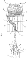
- FIG. 1 shows a plan view of a section of a device for producing a device in individual insulation boards of mineral fibers splittable Faserdämmstoffbahn 1.
- a primary web 2 of a cutting device 3 is supplied, which Cutting device 3 has three bandsaws 4, which the primary web 2 in four side by side lying on a conveyor not shown Part webs 5 divides.
- the partial webs 5 are then passed over each other and then in a region 6 each rotated by 90 ° about its longitudinal axis.
- the meandering deposited partial webs 5 of the primary web 2 are then laterally arranged pressure belts 10 supplied with their pendulum device 7 facing away from each other ends are aligned. Between the printing tapes 10, the partial webs 5 of the primary web 2 are compressed. The partial webs 5 of the primary web 2 form a secondary web at this time 11th
- the secondary web 11 is essentially characterized in that its Einzelfasem predominantly perpendicular to the large surfaces of the secondary web 11 are aligned.
- the mineral fibers in the primary web 2 an orientation substantially parallel to the large Surfaces of the primary nonwoven 2 have. Only in the immediate area of large surfaces are the individual mineral fibers of the secondary web 11 by the compression and the unfolding of the primary web 2 or secondary web 11 substantially parallel to the large surfaces of the secondary web 11 aligned.
- the secondary web 11 is connected to the printing tapes 10 further pressure bands Supplied according to Figure 3, which on the large surfaces of the secondary web 11 act.
- Another cutting device 14 is arranged, which consists of two saws 15, which saws 15 horizontally and parallel to the large surfaces of the secondary web 11 are aligned so that by means of these saws 15 cover layers 16th be separated in the region of both large surfaces of the secondary web 11 can.
- the cover layers 16 comprise the region of the secondary nonwoven 11, which has a Fiber profile arranged parallel to the large surfaces of the secondary nonwoven 11 Mineral fibers.
- the curing oven 13 is a secondary web 11 with almost exclusively perpendicular to the large surfaces of the Sekundärvlieses 11 extending fiber assembly supplied.
- the hardening furnace 13 in turn consists of two acting on the large surfaces Conveyor belts 17, which are permeable to air, so that hot air in Direction of the arrows 18 shown in Figure 3 by the secondary web 11 diffuse can.
- the secondary web 11 is after leaving the curing oven 13 a not fed dryer shown to subsequently after drying to be cut into individual insulation boards.
- FIG. 1 An alternative embodiment of the section according to FIG. 1 is shown in FIG.
- the partial webs individual pendulum devices 19 fed each consisting of two roller conveyors 20, which a decreasing in the conveying direction according to arrow 21 distance from each other to have.
- the individually suspended partial webs 5 are then together two further roller conveyors 100 fed, between which the individually pendulum Part webs 5 are interconnected and compressed.
- the Roller conveyors 100 also have a decreasing direction in the direction of arrow 21 Distance from each other and perform the same task as the Printing tapes 10 of the embodiment according to FIG. 1.
Landscapes
- Engineering & Computer Science (AREA)
- Textile Engineering (AREA)
- Architecture (AREA)
- Chemical & Material Sciences (AREA)
- Inorganic Chemistry (AREA)
- Physics & Mathematics (AREA)
- Civil Engineering (AREA)
- Structural Engineering (AREA)
- Acoustics & Sound (AREA)
- Electromagnetism (AREA)
- Manufacturing & Machinery (AREA)
- Mechanical Engineering (AREA)
- Nonwoven Fabrics (AREA)
Description
Die Erfindung betrifft ein Verfahren zur Herstellung einer insbesondere in einzelne Dämmstoffplatten aus Mineralfasern aufteilbare Faserdämmstoffbahn mit im wesentlichen zu ihren großen Oberflächen rechtwinklig ausgerichteten Mineralfasern, bei dem die Mineralfasern aus einer Sammelkammer abgezogen und auf einem Förderband als Primärvlies mit im wesentlichen parallel zu den großen Oberflächen ausgerichteten Mineralfasern abgelegt werden. Die Erfindung betrifft ferner eine Vorrichtung zur Durchführung des Verfahrens mit einem Förderband zur Förderung eines Primärvlieses aus Mineralfasem von einer Sammelkammer zu einer Pendelstation.The invention relates to a method for producing a particular single Insulation panels of mineral fibers splittable Faserdämmstoffbahn with substantially mineral fibers oriented at right angles to their large surfaces, in which the mineral fibers withdrawn from a collection chamber and on a Conveyor belt as a primary web substantially parallel to the large surfaces aligned mineral fibers are deposited. The invention further relates a device for carrying out the method with a conveyor belt for conveying a primary web of mineral fibers from a collection chamber to a Pendulum station.
Mineralwolle-Dämmstoffe bestehen aus glasig erstarrten Fasern, die zur Erhaltung der elastisch-federnden Eigenschaften, aber auch um als nicht brennbare Dämmstoffe eingestuft werden zu können, nur mit weniger als 8 Masse-%, bei Mineralwolle-Dämmstoffen aus Steinwolle mit ca. 2 bis 4 Masse-% Bindemitteln, insbesondere Phenol-Formaldehyd-Harnstoff-Harzen gebunden sind. Anorganische Bindemittel, wie organische Kieselsäure-Verbindungen, die über Sol-Gel-Prozesse reagieren, werden ebenfalls verwendet. Flexible, kompressible Mineralwolle-Dämmstoffe aus Glaswolle weisen Rohdichten von weniger als 30 kg/m3 auf. Vergleichbare Mineralwolle-Dämmstoffe aus Steinwolle, die nicht unbeträchtliche Anteile nichtfaseriger Bestandteile enthalten, werden mit Rohdichten zwischen ca. 23 bis 45 kg/m3 hergestellt. Darüber hinaus sind mechanisch belastbare Mineralwolle-Dämmstoffe, beispielsweise zur Dämmung von Flachdachkonstruktionen bekannt, die Rohdichten von größer 130 kg/m3 aufweisen. Derartige Dämmstoffe können auch bei Wärmedämmverbundsystemen als Putzträgerplatten eingesetzt werden.Mineral wool insulation materials consist of vitreous solidified fibers, which can be classified as non-combustible insulating materials in order to maintain the elastic-springy properties, but with less than 8% by mass, with mineral wool insulation materials made of rock wool with approx 4% by mass of binders, in particular phenol-formaldehyde-urea resins are bonded. Inorganic binders, such as organic silicic acid compounds that react via sol-gel processes, are also used. Flexible, compressible mineral wool insulation materials made of glass wool have densities of less than 30 kg / m 3 . Comparable mineral wool insulation materials made of rock wool, which contain not inconsiderable amounts of non-fibrous constituents, are produced with densities between approximately 23 to 45 kg / m 3 . In addition, mechanically resilient mineral wool insulating materials, for example, for the insulation of flat roof constructions are known, the bulk densities greater than 130 kg / m 3 have. Such insulating materials can also be used in thermal insulation systems as plaster base plates.
Die mechanischen, wie auch wärmeschutztechnischen Eigenschaften der Mineralwolle-Dämmstoffe sind u.a. abhängig von der Orientierung der einzelnen Fasern. Sind die Fasern quer zu den großen Oberflächen des Mineralwolle-Dämmstoffs ausgerichtet, so ist der Dämmstoff kompressibel. Gleichzeitig weist der Dämmstoff aber auch eine niedrige Querzugfestigkeit und Wärmeleitfähigkeit quer zur Faserorientierung auf. Um Mineralwolle-Dämmstoffe mit großen Festigkeitswerten herzustellen, ist es erforderlich, die einzelnen Fasern überwiegend rechtwinklig zu den großen Oberflächen auszurichten. Hierbei wird in der Regel ein Fasermassenstrom mit seinen darin horizontal und flachgeneigt liegenden Fasern durch eine kontinuierlich wirkende horizontale Stauchung in einem Bereich zwischen 1 zu 2,5 und 1 zu 3 bei gleichzeitig vertikaler Kompression aufgefaltet.The mechanical and thermal properties of mineral wool insulation materials are u.a. depending on the orientation of the individual fibers. Are the fibers across the large surfaces of the mineral wool insulation aligned, the insulation material is compressible. At the same time the insulating material but also a low transverse tensile strength and thermal conductivity transverse to the fiber orientation. To mineral wool insulation materials with high strength values It is necessary to produce the individual fibers predominantly align at right angles to the large surfaces. This is usually a mass flow of fibers with its horizontal and flat inclined fibers inside by a continuous horizontal compression in one area folded between 1 to 2.5 and 1 to 3 with simultaneous vertical compression.
Von außen auf den Fasermassenstrom wirkende Scherkräfte bewirken eine intensive Relativbewegung zwischen den einzelnen Fasern bzw. Faserschichten. Hierdurch kommt es zur Ausbildung von Gleitbahnen mit parallel zueinander orientierten Fasern innerhalb des aufgefalteten Fasernmassenstroms, der nachfolgend als Primärvlies bezeichnet wird. Entlang der Gleitbahnen weist das Primärvlies eine verringerte Haftung zwischen den Fasern bzw. Faserschichten auf. Diese Bereiche verringerter Haftung werden bevorzugt entlang der ursprünglichen Oberflächen des Primärvlieses angeordnet. Es handelt sich hierbei um Faserlagen, die in geringer Materialstärke aus eine Sammelkammer abgezogen und zu größeren Stapeln kontinuierlich übereinander gelegt werden. Beim Transport und dem Übereinanderlegen der Primärvlieslagen werden die Fasern in den oberflächennahen Zonen des Primärvlieses umorientiert. Darüber hinaus sinkt die Klebfähigkeit der in diesen Bereichen angeordneten Bindemitteltropfen, da es hier durch den direkten Kontakt mit der Umgebungsluft zu einem schnellen Antrocknen bzw. Aushärten des Bindemittels kommt. Ferner geht Bindemittelsubstanz an die Fördereinrichtung verloren. Zudem reichem sich auf diesen Oberflächen der Primärvlieslagen bindemittelarme Faserflocken und recycelte Fasern an, die einen Verbund der Fasern in diesem Bereich von vornherein schwächen. Diese Schwächezonen wirken sich insbesondere dann aus, wenn die Dämmstoffe wiederholt oder andauernd hydromechanischen Belastungen während des Gebrauchs ausgesetzt sind. Shearing forces acting on the pulp mass flow from outside cause an intensive Relative movement between the individual fibers or fiber layers. hereby it comes to the formation of slideways with parallel oriented Fibers within the unfolded fiber mass flow following is called primary nonwoven. Along the slideways has the primary web a reduced adhesion between the fibers or fiber layers. These Areas of reduced adhesion are preferred along the original surfaces arranged the primary web. These are fiber layers, the deducted in a small material thickness from a collection chamber and larger Stacking is done continuously. During transport and the Overlaying the primary nonwoven layers, the fibers become near the surface Reoriented zones of the primary web. In addition, the adhesiveness decreases the arranged in these areas binder drops, as it is here through the direct contact with the ambient air for a quick drying or Curing the binder comes. Furthermore, binder substance goes to the conveyor lost. In addition, rich on these surfaces of the primary nonwoven layers low binder fiber flakes and recycled fibers that form a composite weaken the fibers in this area from the outset. These weaknesses In particular, they have an effect if the insulating materials are repeated or constantly exposed to hydromechanical loads during use are.
Die Auf- bzw. Verfaltung der Fasern mit Hilfe der geschilderten Methode ist in der Höhe begrenzt, da sich mit zunehmender Dicke und steigenden Kräften durch Überformung gegenseitige Effekte, wie beispielsweise Parallellagerungen zu den großen Oberflächen einstellen können. Mit zunehmender Materialstärke sinkt auch die Gleichmäßigkeit der Struktur.The Auf- or Verfaltung of the fibers using the method described is in the Height limited, as with increasing thickness and increasing forces through Shaping mutual effects, such as parallel bearings to the can adjust to large surfaces. With increasing material thickness decreases also the uniformity of the structure.
Eine Verbesserung des voranstehend beschriebenen Verfahrens ist dadurch gegeben, daß der Fasermassenstrom durch ein System von Umlenkrollen geführt wird, wodurch die einzelnen Fasern in den Umlenkbereichen horizontal gelagert werden. Dieser zusätzliche Verfahrensschritt hat Auswirkungen auf die Querzugfestigkeit des Primärvlieses. Anstelle von Umlenkrollen kann eine Auffaltung auch mit Hilfe einer um eine horizontale Achse auf- und niederbewegten, d.h. pendelnden Transporteinrichtung erfolgen. Das aufgependelte Primärvlies wird als Sekundärvlies bezeichnet, welches zu einer Erhöhung seiner Querzugfestigkeit dahingehend bearbeitet wird, daß die im Bereich der beiden großen Oberflächen des Sekundärvlieses horizontal gelagerten Fasern nach dem Aushärten des Bindemittels bis in einen Bereich abgetrennt werden, in dem annähernd ausschließlich rechtwinklig zu den großen Oberflächen angeordnete Fasern vorliegen. Bei Dämmstoffen mit geringer Materialstärke von beispielsweise 100 mm müssen bis zu 20% des ursprünglichen Volumens auf diese Art entfernt werden, um ein Mineralwolle-Dämmstoffprodukt zu erzielen, das überwiegend rechtwinklig zu den großen Oberflächen ausgerichteten Einzelfasern hat.An improvement of the method described above is given by that the fiber mass flow passed through a system of pulleys is, whereby the individual fibers stored horizontally in the deflection become. This additional process step has effects on the transverse tensile strength of the primary fleece. Instead of pulleys, a folding can also by moving up and down about a horizontal axis, i. commuting Transport device done. The suspended primary fleece is used as secondary fleece referred to, which is to increase its transverse tensile strength that is processed in the area of the two large surfaces of the Secondary nonwoven horizontally stored fibers after curing of the binder be separated into an area in which almost exclusively fibers are arranged at right angles to the large surfaces. at Insulating materials with a low material thickness of, for example, 100 mm must be up to be removed to 20% of the original volume in this way, a mineral wool insulation product predominantly perpendicular to the large ones Surface-oriented single fibers has.
In einer weiteren Verfahrensvariante wird der endlose Fasermassenstrom vor dem Härteofen in einzelne Abschnitte abgelängt, welche Abschnitte anschließend um 90° gedreht, horizontal zusammengepreßt und vertikal um 20% komprimiert werden. Auch bei diesem Verfahren werden die Fasern unterhalb der großen Oberflächen überwiegend horizontal gelagert, so daß auch diese Bereiche zur Erreichung optimaler Querzugfestigkeit entfernt werden müssen.In a further process variant, the endless fiber mass flow before Hardening furnace cut into sections, which sections subsequently to Rotated 90 °, compressed horizontally and compressed vertically by 20%. Also in this process, the fibers become underneath the large surfaces mostly horizontally stored, so that these areas to achieve optimal transverse tensile strength must be removed.
Nach diesem Verfahren hergestellte Mineralwolle-Dämmstoffe weisen eine maximale Materialstärke von ca. 220 mm auf. Da bei allen Verfahrensvarianten die Auffaltung in Produktionsrichtung erfolgt, sind die Biege-, Zug- und Scherfestigkeit quer zur Produktionsrichtung um ein mehrfaches höher, als in Produktions- und Verfaltungsrichtung. Um hohe Querzugfestigkeiten bei gegebenenfalls sogar reduzierten Rohdichten erzielen zu können, werden Dämmstoffplatten aus derart produzierten Mineralwolledämmstoffen parallel zu der Produktions- und Auffaltungsrichtung entsprechend der gewünschten Dämmstoffdicke in Scheiben geschnitten. Dieser Prozeß ist relativ aufwendig, da er nicht auf der eigentlichen Produktionslinie erfolgen kann, sondern zumeist unter Verwendung großformatiger Platten als Vormaterial auf separaten Schneid- und Umlenkungsanlagen durchgeführt werden muß.Mineral wool insulation materials produced by this process have a maximum Material thickness of about 220 mm. Since in all process variants the Unfolding in the direction of production, are the bending, tensile and shear strength transverse to the production direction by a multiple higher than in production and Verfaltungsrichtung. To high transverse tensile strength at possibly even reduced To be able to achieve gross densities, insulation boards are made of such produced mineral wool insulation parallel to the production and unfolding direction sliced according to the desired insulation thickness. This process is relatively expensive, as it is not on the actual Production line can be done, but mostly using large format Sheets as semi-finished material on separate cutting and deflection systems must be performed.
Derart hergestellte Lamellen-Platten, die häufig als Putzträgerplatten in Wärmedämmverbundsystemen oder als tragende Dämmschicht in Sandwich-Konstruktionen mit Blechen oder Holzwolle-Leichtbauplatten als Deckschichten eingesetzt werden, werden zur Erreichung einer hohen Schub- bzw. Verbindungssteifigkeit sowie einer hohen Querzugfestigkeit einer besonders intensiven Verfaltung der Faserlagen unterzogen. Die Rohdichten derartiger Lamellenplatten liegen in einem Bereich zwischen ca. 70 bis 105 kg/m3.Lamella plates produced in this way, which are often used as plaster base plates in external thermal insulation systems or as load-bearing insulating layer in sandwich constructions with metal sheets or wood wool lightweight panels as cover layers, are used to achieve a high shear or joint stiffness and a high transverse tensile strength of a particularly intensive Subjected to fiber layers. The gross densities of such lamella plates are in a range between about 70 to 105 kg / m 3 .
Zur besseren Haftung von Putzen oder Klebern auf den grundsätzlich hydrophob eingestellten Mineralwolle-Dämmstoffen werden diese zumeist auf einer oder beiden großen Oberflächen mit geeigneten haftvermittelnden Schichten versehen. Der Auftrag dieser Mittel erfolgt durch Sprühen, Gießen, Auffalten, Einreiben oder dergleichen. Sowohl für die Herstellung von großformatigen Sandwich-Elementen als auch die Beschichtung ist es von großem Vorteil, wenn die Lamellenplatten wesentlich größere Formate aufweisen oder als endloses Faserband herstellbar sind.For better adhesion of plasters or adhesives to the basically hydrophobic adjusted mineral wool insulation materials these are mostly on one or both large surfaces provided with suitable adhesion-promoting layers. The application of these funds is done by spraying, pouring, unfolding, rubbing or like. Both for the production of large-sized sandwich elements as well as the coating, it is of great advantage if the lamellar plates have much larger formats or produced as an endless sliver are.
Ausgehend von diesem Stand der Technik liegt der Erfindung die Aufgabe zugrunde, ein gattungsgemäßes Verfahren bzw. eine gattungsgemäße Vorrichtung zur Durchführung des Verfahrens dahingehend zu schaffen, daß Faserdämmstoffbahnen mit einer intensiven Verfaltung der Mineralfasem in einfacher und kostengünstiger Weise herstellbar sind, wobei die mechanischen Eigenschaften in den beiden Hauptachsen der Horizontalebene gleich oder nahezu gleich sind.Starting from this prior art, the invention has for its object to provide a generic method and a generic device for implementing the method to the effect that fiber insulation webs can be prepared with an intense folding of the mineral fibers in a simple and cost-effective manner, whereby the mechanical properties in the two major axes of the horizontal plane are equal or nearly equal.
Die Lösung dieser Aufgabenstellung sieht bei einem erfindungsgemäßen Verfahren vor, daß das Primärvlies durch rechtwinklig zu den großen Oberflächen geführte Schnitte in zumindest zwei, vorzugsweise mehrere, insbesondere gleiche Abmessungen aufweisende Teilbahnen aufgeteilt wird, daß die Teilbahnen anschließend um 90° um ihre Längsachse gedreht werden und daß die Teilbahnen aufgependelt und zu einem Sekundärvlies zusammengefügt werden.The solution of this problem provides in a method according to the invention, that the primary nonwoven is divided by at right angles to the large surfaces cuts in at least two, preferably several, in particular the same dimensions having partial webs that the partial webs are then rotated by 90 ° about its longitudinal axis and that the partial webs are suspended and joined together to form a secondary web.
Bei dem erfindungsgemäßen Verfahren ist somit vorgesehen, daß ein in üblicher Weise hergestelltes Primärvlies in mehrere auf einem Förderband nebeneinander liegende Teilbahnen aufgeteilt wird, welche Teilbahnen anschließend um 90° um ihre Längsachse gedreht werden, woraufhin die Teilbahnen zu einem Sekundärvlies aufgependelt werden. Hierbei kann vorgesehen sein, daß alle Teilbahnen gemeinsam zu einem Sekundärvlies aufgependelt werden oder daß einzelne Teilbahnen aufgependelt und die aufgependelten Teilbahnen zu einem Sekundärvlies zusammengefügt werden.In the method according to the invention is thus provided that in a conventional Way produced primary nonwoven in several on a conveyor belt side by side lying sub-webs is divided, which sub-webs then by 90 ° their longitudinal axis are rotated, whereupon the partial webs to a secondary web be shuttled. It can be provided that all partial webs together be suspended to a secondary web or that individual partial webs suspended and the suspended partial webs to a secondary web be joined together.
Nach einer Weiterbildung der Erfindung ist vorgesehen, daß die Teilbahnen des Primärvlieses vor dem Drehen um ihre Längsachse relativ zur Förderebene übereinander angeordnet werden. Bei diesem Verfahren werden die Teilbahnen nach ihrem Drehen um ihre Längsachse aufgestapelt und gemeinsam einer Pendeleinrichtung zugeführt, die den Stapel der Teilbahnen zu dem Primärvlies aufpendelt. Das Aufpendeln erfolgt in horizontaler Richtung in Förderrichtung eines das Sekundärvlies aufnehmenden Förderbandes.According to a development of the invention it is provided that the partial webs of Primary fleece before turning about its longitudinal axis relative to the conveying plane one above the other to be ordered. In this method, the partial webs are after their rotation stacked around their longitudinal axis and together a pendulum device fed, which bounces the stack of partial webs to the primary web. The pendulum takes place in the horizontal direction in the conveying direction of the secondary web receiving conveyor belt.
Vorzugsweise werden die Teilbahnen und/oder das Sekundärvlies während und/oder nach dem Aufpendeln komprimiert. Insbesondere erfolgt die Kompression in zwei im wesentlichen rechtwinklig zueinander ausgerichteten Richtungen. Durch seitlich angeordnete Druckbänder werden das Sekundärvlies bzw. die Teilbahnen auf die gewünschte Breite komprimiert. Die Verdichtung erfolgt vorzugsweise kontinuierlich, um ein gleichmäßig komprimiertes Produkt zu erzeugen.Preferably, the partial webs and / or the secondary web during and / or compressed after flaring. In particular, the compression takes place in two substantially orthogonal directions. By laterally arranged pressure bands are the secondary web or the partial webs compressed to the desired width. The compression is preferably carried out continuously to produce a uniformly compressed product.
Es ist nach einem weiteren Merkmal der Erfindung vorgesehen, daß das Sekundärvlies anschließend einem Härteofen zugeführt wird, um das Bindemittel auszuhärten.It is provided according to a further feature of the invention that the secondary web then fed to a curing oven to cure the binder.
Es ist weiterhin vorgesehen, daß an den großen Oberflächen des Sekundärvlieses jeweils eine dünne Deckschicht abgetrennt wird. Hierdurch wird eine Faserdämmstoffbahn erzielt, die in weitaus überwiegendem Maße einen Faserverlauf aufweist, der rechtwinklig zu den großen Oberflächen ausgerichtet ist. Durch das Abtrennen der Deckschicht vor dem Härteofen wird der Vorteil erzielt, daß weniger eingebundene Fasern bei ausgehärtetem Bindemittel aus den Oberflächen herausgerissen werden, so daß sich insgesamt eine gleichmäßigere und ebene Oberfläche der Faserdämmstoffbahn ausbildet.It is further contemplated that on the large surfaces of the secondary web in each case a thin cover layer is separated. This is a Faserdämmstoffbahn achieved, the predominantly extent of a grain which is oriented at right angles to the large surfaces. By the Separating the cover layer before the hardening furnace achieves the advantage that less embedded fibers with hardened binder from the surfaces be torn out, so that overall a more even and even Surface of Faserdämmstoffbahn trains.
Die Deckschicht kann sowohl vor oder nach dem Härteofen vom Sekundärvlies abgetrennt werden. In der Deckschicht liegen die Mineralfasern parallel zu den großen Oberflächen vor. Wird die Deckschicht nach dem Härteofen abgetrennt, so ergibt sich hieraus ein marktfähiges Produkt mit ausgesprochen laminarer Struktur, das bei entsprechender Rohdichte beispielsweise für die Trittschalldämmung unter schwimmendem Estrich verwendet werden kann.The cover layer can be before or after the curing oven from the secondary web be separated. In the cover layer, the mineral fibers are parallel to the large surfaces. If the cover layer is separated after the hardening furnace, so this results in a marketable product with pronounced laminar structure, the corresponding density, for example, for impact sound insulation can be used under floating screed.
Bei dem erfindungsgemäßen Verfahren ist somit ergänzend vorgesehen, daß ein in üblicher Weise hergestelltes Primärvlies zu einem Sekundärvlies aufgependelt wird, aus welchem dann einerseits Mineralfaserplatten mit einer Lamellenstruktur und andererseits ein Mineralfaserprodukt mit laminarer Faserstruktur für die Trittschalldämmung hergestellt wird.In the method according to the invention is thus additionally provided that a commuted in a conventional manner primary web to a secondary web suspended becomes, from which then on the one hand mineral fiber plates with a lamellar structure and on the other hand a mineral fiber product with laminar fiber structure for impact sound insulation will be produced.
Nach einer Weiterbildung der Erfindung ist vorgesehen, daß die Deckschicht abgetrennt wird, bevor das Sekundärvlies einem Härteofen zugeführt wird. Bei dieser Ausführungsform weist die Deckschicht nicht ausgehärtetes Bindemittel auf, so dass die Deckschicht nach dem Abtrennen noch hinsichtlich ihrer Materialeigenschaften verändert werden kann. Insbesondere kann die anwendungsspezifisch erforderliche Rohdichte der Deckschicht durch Kompression der Deckschicht bei nicht ausgehärtetem Bindemittel eingestellt werden.According to a development of the invention it is provided that the cover layer separated is before the secondary web is fed to a curing oven. At this Embodiment has the cover layer uncured binder, so that the cover layer after separation nor in terms of their material properties can be changed. In particular, the application-specific required bulk density of the cover layer by compression of the cover layer be set at uncured binder.
Alternativ kann vorgesehen sein, dass die Deckschicht erst nach dem Durchlauf des Sekundärvlieses durch den Härteofen abgetrennt wird.Alternatively it can be provided that the cover layer only after the passage of the secondary web is separated by the curing oven.
Das erfindungsgemäße Verfahren bietet den Vorteil, daß über mehrere Pendel mehrere Vliesschichten zueinander geführt werden, um beispielsweise eine Faserdämmstoffbahn herzustellen, die sandwichartig aufgebaut ist. Hierzu ist vorgesehen, daß das Primärvlies mit einer oder mehreren Vliesschichten, insbesondere unterschiedlicher Eigenschaften zusammengefügt wird. Es können daher beispielsweise Vliesschichten mit höherer und/oder geringerer Rohdichte bzw. mit höherem oder geringerem Kompressionsgrad miteinander verbunden werden, wobei das Zusammenfügen der unterschiedlichen Vliesschichten vor dem Härteofen erfolgt, so daß die Verbindung zwischen den Vliesschichten insbesondere durch das noch nicht ausgehärtete Bindemittel möglich ist.The inventive method has the advantage that over several pendulums a plurality of nonwoven layers are guided to each other, for example, a Faserdämmstoffbahn to produce, which is sandwiched. For this purpose, it is provided that the primary nonwoven fabric with one or more nonwoven layers, in particular different properties is joined together. It can therefore, for example Nonwoven layers with higher and / or lower density or with higher or lower degree of compression, wherein the joining of the different nonwoven layers before the curing oven takes place, so that the connection between the nonwoven layers in particular through the not yet cured binder is possible.
Nach einem weiteren Merkmal der Erfindung ist vorgesehen, daß das Primärvlies vor oder während des Aufpendelns gestaucht wird. Um die Haftung der einzelnen Teilbahnen aneinander zu vergrößern ist vorgesehen, daß die Oberflächen der Teilbahnen mit Bindemitteln imprägniert werden, bevor die Teilbahnen zusammengeführt werden.According to a further feature of the invention it is provided that the primary nonwoven is compressed before or during the pendulum. To the liability of the individual To enlarge part tracks to each other is provided that the surfaces of the Sub-webs are impregnated with binders before the sub-webs merged become.
Eine Weiterbildung des erfindungsgemäßen Verfahrens sieht vor, daß zwischen benachbarten Teilbahnen verstärkende Gewebe und/oder Vliese aus beispielsweise Glas-, Kohlenstoff-, Metall-, temperaturbeständigen Kunststoff- und/oder Naturfasern angeordnet werden. Derartige Gewebe können als Armierung der Faserdämmstoffbahnen dienen und erhöhen die Belastbarkeit der aus dieser Faserdämmstoffbahn hergestellten Dämmstoffplatten. A development of the method according to the invention provides that between adjacent sub-webs reinforcing fabric and / or nonwovens, for example Glass, carbon, metal, temperature resistant plastic and / or Natural fibers are arranged. Such fabrics can be used as reinforcement of the Faserdämmstoffbahnen serve and increase the load capacity of this Faserdämmstoffbahn produced insulating panels.
Das Sekundärvlies wird vorzugsweise vor und/oder im Härteofen rechtwinklig zu seinen großen Oberflächen komprimiert. Auf diese Weise wird eine Faserdämmstoffbahn mit definierten Abmessungen erzeugt, ohne daß die Gefahr eines Aufwölbens der Fasermasse im Härteofen besteht.The secondary web is preferably perpendicular before and / or in the curing oven to compressed its large surfaces. In this way, a fiber insulation sheet produced with defined dimensions, without the risk of bulging the pulp in the curing oven consists.
Vorzugsweise wird im Härteofen Heißluft sowohl rechtwinklig zu den großen Oberflächen, als auch durch die Längsseiten des Sekundärvlieses geleitet, um einen höheren Wirkungsgrad des Härteofens und damit eine verbesserte Aushärtung des Bindemittels zu erzielen. Das Sekundärvlies wird darüber hinaus bis nach der Aushärtung des Bindemittels allseitig eingespannt geführt.Preferably, in the curing oven hot air is both perpendicular to the large Surfaces, as well as passed through the longitudinal sides of the secondary web to a higher efficiency of the curing oven and thus improved curing of the binder to achieve. The secondary web will also be up after hardening of the binder guided clamped on all sides.
Nach dem Aushärten des Bindemittels wird das Sekundärvlies parallel zu seinen großen Oberflächen in einzelne Abschnitte geschnitten. Diese Vorgehensweise hat den Vorteil, daß ein nachgeschalteter Trockner für die Faserdämmstoffbahn in kompakter Bauweise ausgelegt werden kann. Die einzelnen Abschnitte werden neben- und/oder übereinander gestapelt und dem Trockner zugeführt. Selbstverständlich kann auch bereits zu diesem Zeitpunkt die Faserdämmstoffbahn durch rechtwinklig zu ihren großen Oberflächen verlaufende Schnitte in einzelne Platten quaderförmiger Ausgestaltung unterteilt werden. Weiterhin besteht die Möglichkeit, die Längsseiten des Sekundärvlieses nach Aushärten des Bindemittels zur Bildung ebener Flächen zu beschneiden.After curing of the binder, the secondary web becomes parallel to its cut large surfaces into individual sections. This approach has the advantage that a downstream dryer for the fiber insulation in compact design can be designed. The individual sections will be stacked next to and / or on top of each other and fed to the dryer. Of course can already at this time the fiber insulation by cuts perpendicular to their large surfaces in individual plates cuboid configuration can be divided. It is also possible the longitudinal sides of the secondary web after curing of the binder for Crop education flat surfaces.
Die voranstehend genannte, der Erfindung zugrundeliegende Aufgabe wird bei einer gattungsgemäßen Vorrichtung zur Durchführung des voranstehend beschriebenen Verfahrens dadurch gelöst, daß das Förderband eine Schneidvorrichtung aufweist, mit der das Primärvlies in nebeneinander auf dem Förderband liegende Teilbahnen teilbar ist und daß der Schneidvorrichtung eine Dreheinrichtung nachgeschaltet ist, mit der die einzelnen Teilbahnen relativ zu ihrer Längsachse um 90° drehbar sind, bevor sie in die Pendelstation zur Bildung eines Sekundärvlieses einlaufen. The above-mentioned, the invention is based task a generic device for carrying out the above-described Method solved in that the conveyor belt is a cutting device comprising, with the primary web in side by side on the conveyor belt lying partial webs is divisible and that the cutting device is a rotating device is connected downstream, with the individual partial webs relative to its longitudinal axis rotatable by 90 °, before entering the shuttle station to form a secondary web enter.
Die Schneidvorrichtung weist eine der Anzahl n der erforderlichen Teilbahnen entsprechende Anzahl n-1 Sägen auf, die insbesondere als Band- oder Kreissägen ausgebildet sind.The cutting device has one of the number n of the required partial webs corresponding Number of n-1 saws, especially as band or circular saws are formed.
Als Pendelstation werden vorzugsweise paarig angeordnete Druckbänder oder Rollenbahnen für alle Teilbahnen vorgesehen. Alternativ besteht die Möglichkeit, die Pendelstation als paarig angeordnete Druckbänder oder Rollenbahnen für jeweils eine Teilbahn auszubilden, so daß die erfindungsgemäße Vorrichtung eine der Anzahl der Teilbahnen entsprechende Anzahl von paarig angeordneten Druckbändern oder Rollenbahnen aufweist.As pendulum station are preferably paired pressure belts or Roller conveyors intended for all partial webs. Alternatively, it is possible to the shuttle station as paired pressure belts or roller conveyors for each to form a partial web, so that the inventive device a the number of partial webs corresponding number of pairs arranged Has pressure bands or roller conveyors.
Es ist ferner vorgesehen, daß der Pendelstation ein Härteofen mit zumindest zwei Druckbändern nachgeschaltet ist, die auf den großen Oberflächen des Sekundärvlieses aufliegen und durch die ein erwärmtes Gas, insbesondere Heißluft geleitet wird.It is further contemplated that the shuttle station a curing oven with at least two Pressure belts downstream of which is on the large surfaces of the secondary web rest and passed through a heated gas, in particular hot air becomes.
In einer Weiterbildung der Vorrichtung ist vorgesehen, daß im Härteofen zwei weitere Druckbänder vorgesehen sind, die an den Längsseiten des Sekundärvlieses anliegen, so daß das Sekundärvlies bei dieser Ausgestaltung einseitig eingespannt ist und gegebenenfalls in Richtung aller Flächen komprimiert werden kann.In a further development of the device is provided that in the curing oven two further printing tapes are provided, which are on the longitudinal sides of the secondary web abut, so that the secondary web is clamped on one side in this embodiment is and can be compressed if necessary in the direction of all surfaces.
Die an den Längsseiten anliegenden Druckbänder sind relativ zueinander verstellbar im Härteofen angeordnet, so daß sie an unterschiedlich breite Sekundärvliese angepaßt werden können bzw. bei entsprechender Einstellung eine vorgesehene Kompression auf das Sekundärvlies übertragen.The applied pressure bands on the longitudinal sides are adjustable relative to each other arranged in the curing oven, so that they to different widths secondary nonwovens can be adapted or with appropriate setting a planned Transfer compression to the secondary web.
Die an den Längsseiten des Sekundärvlieses anliegenden Druckbänder sind luftdurchlässig ausgebildet und weisen insbesondere Öffnungen auf, durch die erwärmtes Gas, insbesondere Heißluft leitbar ist, um zusätzliche Wärmeenergie in das Sekundärvlies zur Aushärtung des Bindemittels einzubringen. The pressure bands applied to the longitudinal sides of the secondary web are permeable to air formed and in particular have openings through the heated Gas, especially hot air, is conductive to additional heat energy to introduce the secondary web to cure the binder.
Schließlich ist vorgesehen, daß die Öffnung in den an den Längsseiten des Sekundärvlieses anliegenden Druckbändem auf den oberen Bereich, insbesondere die obere Hälfte der Druckbänder beschränkt sind, so daß Strömungskurzschlüsse in dem Sekundärvlies vermieden werden.Finally, it is provided that the opening in the on the longitudinal sides of the secondary web adjacent Druckbändem on the upper area, in particular the upper half of the printing belts are limited so that flow shorts be avoided in the secondary web.
Bei dem erfindungsgemäßen Verfahren bzw. mit der erfindungsgemäßen Vorrichtung wird somit das mit einem Bindemittel imprägnierte, in einer Sammelkammer aufgesammelte Primärvlies in Abhängigkeit von der Breite und der Dicke in zwei oder mehrere Teilbahnen aufgeteilt. Die Teilbahnen werden anschließend übereinandergeleitet und einzeln um 90° um ihre Längsachse umgelenkt und damit auf einer Seite stehend auf ein Sammeltransportband geleitet. Die übereinander angeordneten Teilbahnen werden sodann einem Pendel zugeführt, das aus zwei parallel angeordneten Transportbändern besteht, die um eine gemeinsame vertikale Achse pendeln, so daß die Teilbahnen gemeinsam mäandrierend auf dem Sammeltransportband abgestellt werden.In the method according to the invention or with the device according to the invention Thus, the impregnated with a binder, in a collection chamber collected primary nonwoven depending on the width and the thickness in split two or more sublanes. The partial webs are subsequently superimposed and individually deflected by 90 ° about its longitudinal axis and thus standing on one side and led on a collecting conveyor belt. The one above the other arranged partial webs are then fed to a pendulum, the off two parallel conveyor belts exists, which is a common Vertical axis oscillate, so that the partial webs meandering together parked the collection conveyor belt.
Durch seitlich angeordnete Druckbänder werden die Teilbahnen des Primärvlieses, die in aufgependelter Form das Sekundärvlies bilden, auf eine gewünschte Breite komprimiert. Anstelle einer kontinuierlichen Verdichtung durch Verringerung des gegenseitigen Abstandes der seitlich angeordneten Druckbänder oder Druckrollen kann die Verdichtung auch durch hubartige Bewegung dieser Konstruktionselemente ausgeführt werden. Die Bewegungsrichtung der Druckbänder bzw. der Druckrollen erfolgt vorzugsweise im rechten Winkel zur Förderrichtung des Sekundärvlieses. Es besteht aber auch die Möglichkeit, die Kompression unter einem beliebigen Winkel in Richtung der Förderrichtung auszuführen.By laterally arranged pressure belts, the partial webs of the primary web, which in aufgependelter form the secondary web, to a desired Width compressed. Instead of a continuous compaction by reduction the mutual distance of the laterally arranged pressure belts or pressure rollers The compression can also by stroke-like movement of these construction elements be executed. The direction of movement of the printing tapes or the Pressure rollers are preferably at right angles to the conveying direction of the secondary web. But there is also the possibility of compression under one to execute any angle in the direction of the conveying direction.
Alternativ kann vorgesehen sein, daß das aus der Sammelkammer abgezogene Primärvlies in mehrere Teilbahnen aufgeteilt wird, die anschließend einzelnen pendelnden Fördereinrichtungen, bestehend aus Förderbändern oder Rollensätzen zugeführt werden. Bei dieser Vorgehensweise werden die Teilbahnen einzeln aufgependelt, bevor sie anschließend zusammengeführt und seitlich angeordneten Druckbändern zugeführt werden. Alternatively, it can be provided that the withdrawn from the collection chamber Primary fleece is divided into several sub-webs, which then individual swinging conveyors, consisting of conveyor belts or roller sets be supplied. In this procedure, the partial webs are individually pendulated before being subsequently brought together and arranged laterally Printing tapes are supplied.
Durch eine innerhalb der pendelnden Fördereinrichtung abnehmende Geschwindigkeit und durch eine Verringerung des Abstandes der Transportbänder bzw. Transportrollen, wobei die gegenüberliegenden Transportbänder bzw. Transportrollen relativ zueinander einstelltbar sind, wird eine Verdichtung der Teilbahnen verbunden mit einer intensiven Auf- bzw. Verfaltung der Fasern möglich. Die Verdichtung und Verfaltung der Teilbahnen kann für die einzelnen Teilbahnen individuell vorgenommen werden, so daß beim Zusammenführen der einzelnen Teilbahnen ein Sandwichelement mit Abschnitten unterschiedlicher Charakteristik hergestellt werden kann. Beispielsweise ist es bei der Herstellung breiter Faserdämmstoffbahnen sinnvoll, die inneren Teilbahnen stärker zu verdichten und zu verfalten als die äußeren, um nicht durch zu hohe Seitenkräfte eine unerwünschte unterschiedliche Verdichtung der gesamten Fasermasse bzw. der Faserdämmstoffbahn über die Breite vorzunehmen.By a decreasing within the oscillating conveyor speed and by reducing the distance of the conveyor belts or Transport rollers, wherein the opposite conveyor belts or transport rollers be set relative to each other, is a compaction of the partial webs connected with an intensive Auf- or Verfaltung the fibers possible. The compression and configuration of the partial webs can be customized for the individual partial webs be made so that when merging the individual partial webs a sandwich element with sections of different characteristics can be produced. For example, it is in the production of wide fibrous insulation webs It makes sense to strengthen and condense the inner subpaths Fold as the outer, so as not to unwanted by excessive lateral forces different compression of the entire fiber mass or the Faserdämmstoffbahn across the width.
Um die gegenseitige Haftung der Oberflächen der gemäß der voranstehend beschriebenen Ausführung des erfindungsgemäßen Verfahrens hergestellten Teilbahnen zu verbessern und die Zugfestigkeit der Faserdämmstoffbahn parallel zu den großen Oberflächen zu erhöhen, können die Transportbänder bzw. Transportrollen mit trapezförmig gestalteten Oberflächen, beispielsweise in Schaffußform, ausgebildet sein. Ergänzend können die großen Oberflächen der Teilbahnen zusätzlich mit Bindemitteln imprägniert werden, um die Teilbahnen nach dem Zusammenführen besser aneinander haften zu lassen, wobei das zusätzliche Bindemittel schließlich im nachgeschalteten Härteofen ausgehärtet wird und zu einer weiter verbesserten Haftung der Teilbahnen aneinander beiträgt.To the mutual adhesion of the surfaces of the above-described Execution of the method according to the invention produced partial webs to improve and increase the tensile strength of the fibrous insulation web in parallel To increase the large surfaces, the conveyor belts or transport rollers with trapezoidal shaped surfaces, for example in Schaffußform, be educated. In addition, the large surfaces of the partial webs can additionally impregnated with binders to the partial webs after merging better to adhere to each other, with the additional binder is finally cured in the subsequent hardening furnace and to a further improved adhesion of the partial webs contributes to each other.
Ergänzend können verstärkende Gewebe oder Vliese aus Glas-, Kohlenstoff-, Metall-, temperaturbeständigen Kunststoffen oder Naturfasern an den Seitenflächen der Teilbahnen bzw. des Primärvlieses oder Sekundärvlieses aber auch zwischen den Teilbahnen vorgesehen werden. Die Vliese werden hierbei mit gegenüber den Teilbahnen geringerer Breite zugeführt, da das Primärvlies in einem weiteren Zwischenschritt vor oder nach dem Härteofen an seinen Längsseiten beschnitten wird. Durch die intensive Verfaltung der Teilbahnen bzw. des Sekundärvlieses bilden die eingelegten Gewebe oder Vliese über die gesamte Fläche der aus der Faserdämmstoffbahn gebildeten Dämmstoffplatten wirksame Verstärkungselemente. Diese Verstärkungselemente wirken sich insbesondere im Hinblick auf die Querzugfestigkeit der Dämmplatten aus und vermögen die unvermeidlichen zeitabhängigen, durch hygrothermische und/oder hydromechanische Belastungen bedingten Festigkeitsverluste derartiger Dämmstoffe nicht nur zu kompensieren, sondern führen auch zu mehr Sicherheit in der Anwendung derartiger Dämmstoffe.In addition, reinforcing fabrics or nonwovens made of glass, carbon, Metal, temperature-resistant plastics or natural fibers on the side surfaces the partial webs or the primary web or secondary web but also between the partial webs are provided. The fleeces are here with opposite fed to the partial webs of smaller width, since the primary web in a further intermediate step before or after the hardening furnace on its long sides is cropped. Due to the intensive configuration of the partial webs or the secondary web form the inserted fabric or nonwovens over the entire surface the insulating panels formed from the fiber insulation sheet effective reinforcing elements. These reinforcing elements have an effect, in particular with regard to on the transverse tensile strength of the insulation boards and can do the inevitable time-dependent, by hygrothermal and / or hydromechanical Stress-related strength losses of such insulation not only too but also lead to more safety in the application of such Insulation materials.
Um die Verdichtung und Verfaltung optimal steuern zu können, kann das Sammeltransportband aus mehreren einzelnen Transportbändern oder aus Rollensätzen bzw. Kombinationen beider Konstruktionselemente bestehen, die mit abnehmender Geschwindigkeit betrieben werden und somit eine Stauchung des Sekundärvlieses in der Transportrichtung bewirken. Weiterhin können in Transportrichtung, d.h. über die Breite der Produktionsanlage mehrere schmale Bänder oder Rollensätze verteilt angeordnet sein, die über die Breite der Produktionslinie mit unterschiedlichen Geschwindigkeiten angetrieben werden. Hierdurch wird erreicht, daß die Verdichtung und die Verfaltung auch in den zentralen Bereichen des Sekundärvlieses beeinflußbar ist. Beispielsweise wird ein unteres Transportband durch ein spiegelbildlich angeordnetes oberes Druckband ergänzt, welches auf die zu verfaltende bzw. verdichtende Fasermasse einwirkt. Dieses Druckband hat in erster Linie die Aufgabe, die Verfaltung zu begünstigen, wobei eine zu große Verdichtung in horizontaler Richtung möglichst ausgeschlossen sein soll. Zur Unterstützung der verfaltenden Wirkung in der Transportrichtung können die unteren und oberen Teilbänder mit aus ihrer Oberfläche hervorstehenden Vorsprüngen ausgebildet sein, die in die Fasermasse, insbesondere das Sekundärvlies eingreifen und die Fasern relativ zueinander bewegen.In order to be able to optimally control the compaction and configuration, the collection conveyor belt can from several individual conveyor belts or roller sets or combinations of both construction elements exist with decreasing Speed are operated and thus a compression of the secondary web effect in the transport direction. Furthermore, in the transport direction, i.e. across the width of the production plant several narrow bands or Roller sets can be arranged distributed across the width of the production line be driven at different speeds. This will achieve that the compaction and the framing also in the central areas of the secondary web can be influenced. For example, a lower conveyor belt supplemented by a mirror-image arranged upper pressure band, which on the pulp mass to be folded or compressed acts. This print tape has first and foremost the task of favoring the composition, with a too large one Compression in the horizontal direction should be excluded as possible. For support the folding effect in the transport direction, the lower and upper subbands with projections protruding from their surface be formed, which engage in the pulp, in particular the secondary web and move the fibers relative to each other.
Das Sekundärvlies kann eine Materialstärke zwischen 200 und 2000 mm bei einer Rohdichte von ca. 40 bis 300 kg/m3 aufweisen. In diesem Zustand erweist das Sekundärvlies im Bereich unterhalb seiner großen Oberflächen in bestimmter Tiefe Fasern auf, die nicht im wesentlichen rechtwinklig zu den großen Oberflächen ausgebildet sind. Da eine Faserdämmstoffbahn hergestellt werden soll, die annähernd ausschließlich rechtwinklig zu den großen Oberflächen ausgerichtete Mineralfasern aufweist, werden diese Bereiche nachfolgend durch horizontal geführte Schnittwerkzeuge vom Sekundärvlies abgetrennt. Die abgetrennten Fasern können in bekannter Weise einem internen Recyclingprozeß zugeführt und wieder aufgeschmolzen werden. Es besteht aber auch die Möglichkeit, daß die abgetrennten Faserlagen nach entsprechender Auflockerung wieder dem Primärvlies direkt oder dem Fasermassenstrom in der Sammelkammer zugeführt werden.The secondary web can have a thickness between 200 and 2000 mm with a bulk density of about 40 to 300 kg / m 3 . In this state, the secondary non-woven fabric in the region below its large surfaces at certain depth fibers, which are not formed substantially perpendicular to the large surfaces. Since a Faserdämmstoffbahn is to be produced, which has almost exclusively aligned at right angles to the large surfaces mineral fibers, these areas are subsequently separated by horizontally guided cutting tools from the secondary web. The separated fibers can be fed to an internal recycling process in a known manner and remelted. However, there is also the possibility that the separated fiber layers are again fed to the primary web directly or the fiber mass flow in the collection chamber after appropriate loosening.
Da das Sekundärvlies vor allem durch die seitlichen Druckbänder zusammengehalten wird, ist die durch das Eigengewicht mögliche Umorientierung der Mineralfasem im Auflagenbereich der Faserbahn gering. Ein oberes Druckband erzeugt hierbei nur soviel Pressung, daß ein Aufwölben des Sekundärvlieses durch den Druck der seitlichen Profilbänder verhindert wird. Gleichzeitig dient dieses luftdurchlässige, auf der Oberfläche des Sekundärvlieses aufliegende Band der kontrollierten Durchführung der zum Austrocknen der vorhandenen Feuchte und zum Aushärten des Bindemittels benötigten Heißluft. Dieses Trocknen erfolgt in einem Härteofen.Since the secondary web held together mainly by the lateral pressure bands is the possible reorientation of the mineral fibers due to its own weight low in the contact area of the fibrous web. An upper pressure band is generated Here only so much pressure that a bulging of the secondary web through the Pressure of the side profile strips is prevented. At the same time, this air-permeable, on the surface of the secondary nonwoven tape lying on the controlled Carrying out the drying of the existing moisture and the Curing the binder required hot air. This drying takes place in one Curing oven.
Ein solcher Härteofen besteht in der Regel aus zwei stabilen übereinander angeordneten Druckbändern, durch die Heißluft gesaugt wird. Bei Höhen von Sekundärvliesen von weniger als 200 mm wird auf die Abdichtung der Seitenflächen des Sekundärvlieses kein besonderer Wert gelegt. Das Sekundärvlies verbleibt ca. 2 bis 15 Minuten, vorzugsweise weniger als 10 Minuten in dem Härteofen, so daß relativ heiße Luft mit Temperaturen von ca. 250 bis 320°C eingesetzt werden muß, um eine ausreichende Aushärtung des Bindemittels zu erzielen. Hierbei ist darauf zu achten, daß eine Zerstörung der organischen Substanz des Bindemittels vermieden wird, da hierdurch Verfärbungen auftreten, die zur Unverkäuflichkeit des hergestellten Produktes führen können. Bei derartigen Temperaturen sind darüber hinaus die zur Hydrophobierung der Fasern zugefügten Öle, Öl-Emulsionen oder dergleichen noch nicht im wesentlichen Umfang flüchtig. Such a curing oven is usually made of two stable stacked Pressure belts through which hot air is sucked. At heights of secondary nonwovens of less than 200 mm is applied to the sealing of the side surfaces of the Secondary fleece no special value. The secondary web remains about 2 to 15 minutes, preferably less than 10 minutes in the curing oven, so that relatively hot air with temperatures of about 250 to 320 ° C are used must be in order to achieve sufficient curing of the binder. Here is take care that a destruction of the organic substance of the binder is avoided, as this discoloration occur, the for sale of the product produced. At such temperatures are In addition, the added to the hydrophobization of the fibers oils, oil emulsions or the like is not yet substantially voluminous.
Die mit dem erfindungsgemäßen Verfahren vorgestellten Sekundärvliese haben eine Breite zwischen 500 und 2400 mm Breite sowie Materialstärken bis zu 2000 mm. Die Führung der Heißluft durch das Sekundärvlies geschieht naturgemäß auf dem kürzesten Weg, d.h. bei den aufgezeigten Variationen zwischen Dicken und Breiten sowohl von oben nach unten bzw. umgekehrt und in abschnittsweiser Umkehrung. Durch die Verwendung von seitlichen Druckbändern, die ebenfalls teilweise luftdurchlässig ausgebildet sind, kann ergänzend Heißluft kontinuierlich von oben nach unten durch die Fasermasse gesaugt oder gedrückt und zusätzlich über die seitlichen Druckbänder eingegeben oder abgezogen werden. Durch die vorhandenen Öffnungen kann soviel Energie übertragen werden, wie sie zum Austrocknen und Aushärten der organischen Bindemittel, wie beispielsweise Phenol-, Formaldehyd-, Harnstoff-Harz-Gemischen oder dergleichen mit samt der vorhandenen Feuchte in einer Größenordnung von 3 bis 10 Masse-% innerhalb von ca. 2 bis 8 Minuten benötigt wird, wobei das Sekundärvlies auf eine Temperatur von ca. 120 bis 170°C aufgeheizt wird. Bei Verwendung von Bindemitteln, wie als Nanopartikel dispergierte Kieselsäure, die über Sol-Gel-Prozesse aushärten, sind entsprechende Veränderungen der Aufheiz- und Haltezeit vorzusehen.The secondary webs presented by the method according to the invention have a width between 500 and 2400 mm width and material thicknesses up to 2000 mm. The leadership of the hot air through the secondary web naturally occurs the shortest path, i. in the indicated variations between thicknesses and Widths from top to bottom or vice versa and in sections Reversal. By the use of side pressure bands, which also Partially permeable to air, hot air can be added continuously from top to bottom sucked or pressed by the fiber mass and in addition can be entered or removed via the side print bands. By the existing openings can be transferred as much energy as they are to Drying and curing of organic binders such as phenol, Formaldehyde, urea-resin mixtures or the like together with the existing moisture in the order of 3 to 10% by mass within of about 2 to 8 minutes is needed, with the secondary web at a temperature from about 120 to 170 ° C is heated. When using binders, such as silicic acid dispersed as nanoparticles, which cure via sol-gel processes, appropriate changes of the heating and holding time are to be provided.
Nach dem Aushärten des Bindemittels im Härteofen ist die Struktur des Sekundärvlieses fixiert, so daß das endlose Sekundärvlies frei transportiert werden kann. Das Sekundärvlies wird nun zur Vermeidung von Energieverlusten in einen beheizten und ausreichend wärmegedämmten Trockenkanal geleitet, in dem das in Einschlüssen bzw. dem dort angereicherten Harz vorhandene Wasser verdampfen kann. Bei einer Temperatur von ca. 150°C ist eine Trockenzeit von ca. 40 bis 80 Minuten vorgesehen. Durch eine Vortrocknung der Luft in dem Trockenkanal auf kleiner 30% relative Feuchte wird der Trockenvorgang wirkungsvoll unterstützt bzw. gegebenenfalls abgekürzt.After curing of the binder in the curing oven is the structure of the secondary nonwoven fixed, so that the endless secondary web are transported freely can. The secondary web is now to avoid energy loss in one heated and sufficiently thermally insulated drying duct passed, in which the evaporate in inclusions or the enriched there resin existing water can. At a temperature of approx. 150 ° C, a drying time of approx. 40 to 80 minutes provided. By predrying the air in the drying channel at a relative humidity of less than 30%, the drying process is effectively supported or abbreviated as appropriate.
Nach dem Verlassen des Trockenkanals wird die Fasermasse durch Raumluft abgekühlt. Der Energiegehalt der Abluft kann zur Erwärmung der Trocknerluft verwendet werden. Das endlose Sekundärvlies wird nun horizontal aufgeschnitten bzw. in einzelne Abschnitte aufgeteilt, die dann Dämmstoffplatten bilden. Um eine kompaktere Bauweise, insbesondere eine Verringerung der Länge des nachgeschalteten Trockners zu erreichen, kann das Sekundärvlies nach dem Aushärten des Bindemittels im Härteofen in Abschnitte unterteilt werden. Diese blockartigen Abschnitte werden neben- und/oder übereinander gestapelt. Die durch diese Vorgehensweise eingetretenen Energieverluste müssen durch eine entsprechende Erhöhung der Temperatur, insbesondere aber durch eine längere Verweilzeit in dem Trockner kompensiert werden. In einer weiteren Variante wird das Sekundärvlies nach dem Aushärten des Bindemittels konventionell durch Raumluft heruntergekühlt und in Dämmstoffplatten mit den gewünschten Abmessungen horizontal und vertikal aufgeteilt. Diese Dämmstoffplatten werden anschließend einzeln oder in Stapeln über ein luftdurchlässiges Band geleitet und mittels Heißluft auf ca. 120 bis 170°C, vorzugsweise 150 bis 160°C aufgeheizt und anschließend zur Vermeidung von Energieverlusten zu größeren Einheiten aufgestapelt und entsprechend der beschriebenen Verfahrenstechnik nachgetrocknet.After leaving the drying channel, the pulp becomes air in the room cooled. The energy content of the exhaust air can be used to heat the dryer air be used. The endless secondary web is now cut horizontally or divided into individual sections, which then form insulating panels. To one more compact design, in particular a reduction in the length of the downstream Trockners can reach the secondary web after curing of the binder are divided into sections in the hardening furnace. This block-like Sections are stacked next to and / or above each other. The by this procedure incurred energy losses must be replaced by a corresponding Increase of the temperature, but especially by a longer residence time in be compensated for the dryer. In a further variant, the secondary nonwoven cooled down conventionally by room air after curing of the binder and horizontally in insulation boards of the desired dimensions and split vertically. These insulation boards are then individually or passed in stacks over an air-permeable belt and by means of hot air heated to about 120 to 170 ° C, preferably 150 to 160 ° C and then piled up to larger units to prevent energy losses and nachgetrocknet according to the described process technology.
Weitere Merkmale und Vorteile der Erfindung ergeben sich aus der nachfolgenden Beschreibung der zugehörigen Zeichnung. In der Zeichnung zeigen:
Figur 1- eine erste Ausführung eines Abschnitts einer Vorrichtung zur Durchführung eines Verfahrens zur Herstellung einer Faserdämmstoffbahn in Draufsicht;
- Figur 2
- eine zweite Ausführungsform eines Abschnitts einer Vorrichtung zur Durchführung eines Verfahrens zur Herstellung einer Faserdämmstoffbahn und
- Figur 3
- ein weiterer Abschnitt der Vorrichtung gemäß
den Figuren 1 oder 2 in Seitenansicht.
- FIG. 1
- a first embodiment of a portion of an apparatus for carrying out a method for producing a Faserdämmstoffbahn in plan view;
- FIG. 2
- a second embodiment of a portion of an apparatus for carrying out a method for producing a Faserdämmstoffbahn and
- FIG. 3
- a further section of the device according to the figures 1 or 2 in side view.
Figur 1 zeigt in Draufsicht einen Abschnitt einer Vorrichtung zur Herstellung einer
in einzelne Dämmstoffplatten aus Mineralfasern aufteilbaren Faserdämmstoffbahn
1. Hierzu wird ein Primärvlies 2 einer Schneidvorrichtung 3 zugeführt, welche
Schneidvorrichtung 3 drei Bandsägen 4 aufweist, welche das Primärvlies 2 in vier
nebeneinander auf einer nicht näher dargestellten Fördereinrichtung liegende
Teilbahnen 5 aufteilt.FIG. 1 shows a plan view of a section of a device for producing a device
in individual insulation boards of mineral fibers splittable
Die Teilbahnen 5 werden anschließend übereinander geführt und anschließend in einem Bereich 6 jeweils um 90° um ihre Längsachse gedreht.The partial webs 5 are then passed over each other and then in a region 6 each rotated by 90 ° about its longitudinal axis.
Diese einzeln um 90° gedrehten und weiterhin übereinander angeordneten Teilbahnen
5 werden anschließend einer Pendeleinrichtung 7 zugeführt, die aus zwei
parallel zueinander ausgerichteten und im Abstand zueinander angeordneten
Druckbändem 8 besteht, welche Druckbänder 8 um eine gemeinsame vertikale
Achse pendeln und die Teilbahnen 5 des Primärvlieses 2 mäandrierend auf einer
Fördereinrichtung 9 ablegen.These individually rotated by 90 ° and continue stacked sub-webs
5 are then fed to a shuttle 7, which consists of two
parallel to each other and spaced apart
Die mäandrierend abgelegten Teilbahnen 5 des Primärvlieses 2 werden anschließend
seitlich angeordneten Druckbändern 10 zugeführt, die mit ihren der Pendeleinrichtung
7 abgewandten Enden aufeinander zulaufend ausgerichtet sind. Zwischen
den Druckbändern 10 werden die Teilbahnen 5 des Primärvlieses 2 komprimiert.
Die Teilbahnen 5 des Primärvlieses 2 bilden zu diesem Zeitpunkt ein Sekundärvlies
11.The meandering deposited partial webs 5 of the primary web 2 are then
laterally arranged
Das Sekundärvlies 11 ist im wesentlichen dadurch charakterisiert, daß seine Einzelfasem
überwiegend rechtwinklig zu den großen Oberflächen des Sekundärvlieses
11 ausgerichtet sind. Hierzu ist ergänzend auszuführen, daß die Mineralfasern
im Primärvlies 2 eine Ausrichtung im wesentlichen parallel zu den großen
Oberflächen des Primärvlieses 2 haben. Lediglich im unmittelbaren Bereich der
großen Oberflächen sind die einzelnen Mineralfasern des Sekundärvlieses 11
durch die Kompression und die Auffaltung des Primärvlieses 2 bzw. Sekundärvlieses
11 im wesentlichen parallel zu den großen Oberflächen des Sekundärvlieses
11 ausgerichtet. The
Das Sekundärvlies 11 wird im Anschluß an die Druckbänder 10 weiteren Druckbändern
12 gemäß Figur 3 zugeführt, die auf die großen Oberflächen des Sekundärvlieses
11 wirken. Zwischen den Druckbändem 12 und einem Härteofen 13 ist
eine weitere Schneideinrichtung 14 angeordnet, die aus zwei Sägen 15 besteht,
welche Sägen 15 horizontal und parallel zu den großen Oberflächen des Sekundärvlieses
11 ausgerichtet sind, so daß mittels dieser Sägen 15 Deckschichten 16
im Bereich beider großen Oberflächen des Sekundärvlieses 11 abgetrennt werden
können.The
Die Deckschichten 16 umfassen den Bereich des Sekundärvlieses 11, der eine
Faserverlauf mit parallel zu den großen Oberflächen des Sekundärvlieses 11 angeordneten
Mineralfasern aufweist. Somit wird dem Härteofen 13 ein Sekundärvlies
11 mit annähernd ausschließlich rechtwinklig zu den großen Oberflächen des
Sekundärvlieses 11 verlaufender Faseranordnung zugeführt.The cover layers 16 comprise the region of the
Der Härteofen 13 besteht wiederum aus zwei auf die großen Oberflächen einwirkenden
Förderbänder 17, die luftdurchlässig ausgebildet sind, so daß Heißluft in
Richtung der in Figur 3 dargestellten Pfeile 18 durch das Sekundärvlies 11 diffundieren
kann.The hardening
Das Sekundärvlies 11 wird nach dem Verlassen des Härteofens 13 einem nicht
näher dargestellten Trockner zugeführt, um anschließend nach dem Austrocknen
in einzelne Dämmstoffplatten aufgeschnitten zu werden.The
Eine alternative Ausgestaltung des Abschnitts gemäß Figur 1 ist in Figur 2 dargestellt.
Bei dieser Ausführungsform werden die Teilbahnen einzelnen Pendeleinrichtungen
19 zugeführt, die jeweils aus zwei Rollenbahnen 20 bestehen, welche
einen sich in Förderrichtung gemäß Pfeil 21 verringernden Abstand zueinander
haben. Die einzeln aufgependelten Teilbahnen 5 werden anschließend gemeinsam
zwei weiteren Rollenbahnen 100 zugeführt, zwischen denen die einzeln aufgependelten
Teilbahnen 5 miteinander verbunden und komprimiert werden. Die
Rollenbahnen 100 weisen ebenfalls einen in Förderrichtung gemäß Pfeil 21 abnehmenden
Abstand voneinander auf und erfüllen die gleiche Aufgabe, wie die
Druckbänder 10 der Ausführungsform gemäß Figur 1.An alternative embodiment of the section according to FIG. 1 is shown in FIG.
In this embodiment, the partial webs
Claims (32)
- Process for manufacturing a fibrous insulation web (1), particularly one which can be divided in individual mineral fiber insulation boards having the mineral fibers substantially aligend at right angles to the large surfaces thereof, in which process said mineral fibers are drawn off from a collecting chamber and are deposited on a conveyor belt as a primary fibrous web (2) having the mineral fibers aligned substantially parallel to the large surfaces,
characterized in that said primary fibrous web (2) is divided in at least two and preferably more partial webs (5) particularly having equal dimensions by cuts being made at right angles to the large surfaces,
that said partial webs (5) are thereafter turned about their longitudinal axis by 90°, and
that said partial webs (5) are treated in a pendulum fashion and combined into a secondary fibrous web (11). - Process according to claim 1,
characterized in that prior to being turned about their longitudinal axis relative to their conveying plane said partial webs (5) of said primary fibrous web (2) are arranged one above the other. - Process according to claim 1,
characterized in that said partial webs (5) and/or said secondary fibrous web (11) are or is compressed during and/or after said treatment in a pendulum fashion. - Process according to claim 3,
characterized in that said compression is effected in two directions substantially aligned at right angles to each other. - Process according to claim 1,
characterized in that said secondary fibrous web (11) is advanced to a hardening furnace (13). - Process according to claim 1,
characterized in that each of the large surfaces of said secondary fibrous web (11) is having a thin cover layer (16) separated therefrom. - Process according to claim 6,
characterized in that from said thin cover layer (16) which is separated from at least one of the large surfaces of said secondary fibrous web (11) a mineral fiber product with a laminar structure is formed for impact sound proofing particularly under a floating floor. - Process according to claim 6,
characterized in that said cover layer (16) is separated prior to advancing said secondary fibrous web (11) to a hardening furnace (13). - Process according to claim 6,
characterized in that said cover layer (16) is advanced to said hardening furnace (13) separately of said secondary fibrous web (11). - Process according to claim 6,
characterized in that said cover layer (16) is compressed to a bulk density as required by its specific application before the hardening furnace (13). - Process according to claim 6,
characterized in that said cover layer (16) is separated after advancing said secondary fibrous web (11) to a hardening furnace (13). - Process according to claim 1,
characterized in that said primary fibrous web (2) is combined with one or more fibrous web layers which particularly have different properties. - Process according to claim 1,
characterized in that said primary fibrous web (2) is upset prior to or during said treatment in a pendulum fashion. - Process according to claim 1,
characterized in that the surfaces of said partial webs (5) or of said cover layer (16) are impregnated with binders. - Process according to claim 1,
characterized in that between adjacent partial webs (5) reinforcing fabrics and/or webs for example of glass, carbon, metal, temperature-resistant synthetic and/or natural fibers are arranged. - Process according to claim 1,
characterized in that said secondary fibrous web (11) and/or said cover layer (16) is compressed at right angles to its large surfaces before and/or in said hardening furnace (13). - Process according to claim 1,
characterized in that a structure is impressed in the large surfaces of said secondary fibrous web (11). - Process according to claim 5,
characterized in that within said hardening furnace (13) hot air is introduced both at right angles to the large surfaces and through the longitudinal sides of said secondary fibrous web (11) or said cover layer (16). - Process according to claim 1,
characterized in that said secondary fibrous web (11) or said cover layer (16) is guided in a polydirectionally clamped state until after the curing of the binder. - Process according to claim 1,
characterized in that said secondary fibrous web (11) or said cover layer (16) is cut to individual sections parallel to its large surfaces after the curing of the binder. - Process according to claim 1,
characterized in that after curing of the binder said secondary fibrous web (11) or said cover layer (16) is divisioned in individual boards of a cuboid shape by cuts running at right angles to its large surfaces. - Process according to claim 1,
characterized in that after the curing of the binder said secondary fibrous web (11) or said cover layer (16) is trimmed on the longitudinal sides thereof for forming plane surfaces. - Process according to claim 5,
characterized in that said secondary fibrous web (11) or said cover layer (16) is advanced to a drying conduit after said hardening furnace (13). - Device for carrying out the method according to one of the claims 1 to 18, said device comprising a conveyor belt (9) for conveying a primary fibrous web (2) of mineral fibers from a collecting chamber to a pendulum device (7),
characterized in that said conveyor belt includes a cutting device (3) by means of which said primary fibrous web (2) can be divided in partial webs (5) juxtaposed on said conveying belt, and that said cutting device (3) includes a downstream turning means by which said individual partial webs (5) can by turned by 90° with respect to their longitudinal axis before they enter said pendulum device (7) for forming a secondary fibrous web (11). - Device according to claim 19,
characterized in that said cutting device includes saws in a number n-1 corresponding to the number of required partial webs (5), which saws are particularly in the form of belt saws (4) or circular saws. - Device according to claim 19,
characterized in that said pendulum device (7) is in the form of pressure belts (10) or roller belts (100) arranged as a pair for all said partial webs (5). - Device according to claim 19,
characterized in that said pendulum device (7) is in the form of pressure belts or roller belts (20) arranged as a pair for one partial web (5) respectively. - Device according to claim 19,
characterized in that said pendulum device (7) includes a downstream hardening furnace (13) with at least two pressure belts (17) resting on the large surfaces of said secondary fibrous web (11) and having a heated gas, particularly hot air passed therethrough. - Device according to claim 23,
characterized in that in said hardening furnace (13) two pressure belts are provided abutting the longitudinal sides of said secondary fibrous web (11). - Device according to claim 23 and/or claim 24,
characterized in that said pressure belts are mutually adjustably arranged in said hardening furnace (13). - Device according to claim 24,
characterized in that said pressure belts (17) are air-permeable, particularly having openings through which a heated gas, particularly air can be passed. - Device according to claim 26,
characterized in that said openings are limited to the upper region, particularly the upper halves of said pressure belts.
Priority Applications (1)
| Application Number | Priority Date | Filing Date | Title |
|---|---|---|---|
| EP00710034A EP1106743B1 (en) | 1999-12-08 | 2000-11-20 | Process and device for manufacturing a fibrous insulation web |
Applications Claiming Priority (5)
| Application Number | Priority Date | Filing Date | Title |
|---|---|---|---|
| DE19958973 | 1999-12-08 | ||
| DE19958973A DE19958973C2 (en) | 1999-12-08 | 1999-12-08 | Method and device for producing a fiber insulation web |
| EP00123506 | 2000-10-27 | ||
| EP00123506 | 2000-10-27 | ||
| EP00710034A EP1106743B1 (en) | 1999-12-08 | 2000-11-20 | Process and device for manufacturing a fibrous insulation web |
Publications (3)
| Publication Number | Publication Date |
|---|---|
| EP1106743A2 EP1106743A2 (en) | 2001-06-13 |
| EP1106743A3 EP1106743A3 (en) | 2003-01-15 |
| EP1106743B1 true EP1106743B1 (en) | 2005-04-06 |
Family
ID=34317033
Family Applications (1)
| Application Number | Title | Priority Date | Filing Date |
|---|---|---|---|
| EP00710034A Expired - Lifetime EP1106743B1 (en) | 1999-12-08 | 2000-11-20 | Process and device for manufacturing a fibrous insulation web |
Country Status (1)
| Country | Link |
|---|---|
| EP (1) | EP1106743B1 (en) |
Families Citing this family (4)
| Publication number | Priority date | Publication date | Assignee | Title |
|---|---|---|---|---|
| DE102005026656A1 (en) * | 2004-07-09 | 2006-02-02 | Deutsche Rockwool Mineralwoll Gmbh & Co. Ohg | Production of a mineral fiber web with largely upright mineral fibers and use of the resulting waste |
| DE102005044051A1 (en) * | 2004-10-15 | 2006-05-04 | Deutsche Rockwool Mineralwoll Gmbh + Co Ohg | Building roof as well as insulating layer construction and mineral fiber insulating element for a building roof |
| DE102012018481A1 (en) * | 2012-09-19 | 2014-03-20 | Sandler Ag | insulation |
| WO2018156691A1 (en) * | 2017-02-23 | 2018-08-30 | Zephyros, Inc. | Nonwoven fiber structure for use as an insulator |
Family Cites Families (8)
| Publication number | Priority date | Publication date | Assignee | Title |
|---|---|---|---|---|
| FR1479960A (en) * | 1965-05-17 | 1967-05-05 | Du Pont | Process for preparing fibrous sheets with generally upright fibers |
| BE795596A (en) * | 1972-02-17 | 1973-06-18 | Rockwool Ab | METHOD AND SYSTEM FOR MANUFACTURING A MINERAL WOOL LAMINATE PRODUCT AND FOR MAKING IT COHERENT |
| DE2501045A1 (en) * | 1975-01-13 | 1976-07-15 | Ihlefeld Karl Helmut | Cutting laminates from mineral wool slabs - continuous process has vertical revolving cutters |
| DE3701592A1 (en) * | 1987-01-21 | 1988-08-04 | Rockwool Mineralwolle | METHOD FOR CONTINUOUSLY PRODUCING A FIBER INSULATION SHEET AND DEVICE FOR IMPLEMENTING THE METHOD |
| DK165926B (en) * | 1990-12-07 | 1993-02-08 | Rockwool Int | PROCEDURE FOR THE MANUFACTURE OF INSULATION PLATES COMPOSED BY INVOLVED CONNECTED STABLE MINERAL FIBER ELEMENTS |
| DK42794A (en) * | 1994-04-13 | 1995-10-14 | Rockwool Int | Plate insulating element |
| DE4432866C1 (en) * | 1994-09-15 | 1996-02-01 | Rockwool Mineralwolle | Mineral wool fibre material prodn. in vertical layers |
| CA2184836C (en) * | 1996-09-04 | 2000-03-14 | Jung-Fu Chien | Method for producing a variable density, corrugated resin-bonded or thermo-bonded fiberfill and the structure produced thereby |
-
2000
- 2000-11-20 EP EP00710034A patent/EP1106743B1/en not_active Expired - Lifetime
Also Published As
| Publication number | Publication date |
|---|---|
| EP1106743A2 (en) | 2001-06-13 |
| EP1106743A3 (en) | 2003-01-15 |
Similar Documents
| Publication | Publication Date | Title |
|---|---|---|
| DE69104730T2 (en) | METHOD FOR THE PRODUCTION OF INSULATING PANELS CONSTRUCTED FROM INTERMEDIATE TUBE MINERAL FIBER ELEMENTS. | |
| DE3701592C2 (en) | ||
| DE69530181T3 (en) | Process for producing a mineral fiber web | |
| DE69425051T3 (en) | METHOD FOR PRODUCING AN ISOLATING MINERAL FIBER RAILWAY | |
| DE69708613T2 (en) | METHOD AND DEVICE FOR PRODUCING A MINERAL FIBER PANEL | |
| DE69909454T2 (en) | METHOD AND DEVICE FOR PRODUCING A MINERAL FIBER PRODUCT. | |
| DE4419044A1 (en) | Method and device for producing an insulation structure | |
| EP1616985A1 (en) | Manufacture of a mineral fibre web with substantially upright fibres | |
| DE69421267T2 (en) | METHOD FOR PRODUCING A MINERAL FIBER INSULATION FABRIC AND SYSTEM FOR PRODUCING A MINERAL FIBER FABRIC | |
| EP1106743B1 (en) | Process and device for manufacturing a fibrous insulation web | |
| DE2307577B2 (en) | PROCESS FOR PRODUCING FLAT MINERAL WOOL PANELS AND SYSTEM FOR CARRYING OUT THE PROCESS | |
| EP1708876B1 (en) | Method for the production of a web of insulating material and web of insulating material | |
| EP1559845B1 (en) | Process for manufacturing an insulating mat of mineral fibres and insulating mat | |
| DE68921221T2 (en) | METHOD AND DEVICE FOR PRODUCING PLATES FROM MINERAL WOOL. | |
| EP1561847B1 (en) | Method and apparatus for manufacturing insulating webs or plates from mineral fibers | |
| DE19958973C2 (en) | Method and device for producing a fiber insulation web | |
| DE102004047193A1 (en) | Insulation material strip manufacture involves production of mineral fiber fleece which is gathered and cut along the center parallel to outer faces before coating layer is applied to cut surface | |
| DE10057431C2 (en) | Use of top layers of a fiber insulation sheet | |
| EP3276064B1 (en) | Sandwich core comprising a fibre material and method for its preparation and sandwich panel | |
| AT516749B1 (en) | Method and device for producing insulating elements from mineral fibers | |
| AT405845B (en) | METHOD FOR THE PRODUCTION OF A MINERAL FIBER LAMINATED SHEET AND DEVICE FOR IMPLEMENTING THE METHOD | |
| DE10057430A1 (en) | Method of manufacturing glass fiber core thermal insulation panels involves drawing mineral fibers as primary web, sub-dividing into secondary web, rotating, recombining and surrendering into a sideways pendulum feed on moving conveyor belt | |
| CH692114A5 (en) | Process and apparatus for producing mineral fibreboard | |
| DE102005002649A1 (en) | Manufacturing rolls or slabs of mineral fiber insulation, passes laid mineral fiber into stretching station at right angles to conveying direction, before entry into hardening oven | |
| WO2009043492A2 (en) | Method and apparatus for the production of insulating elements |
Legal Events
| Date | Code | Title | Description |
|---|---|---|---|
| PUAI | Public reference made under article 153(3) epc to a published international application that has entered the european phase |
Free format text: ORIGINAL CODE: 0009012 |
|
| AK | Designated contracting states |
Kind code of ref document: A2 Designated state(s): AT BE CH CY DE DK ES FI FR GB GR IE IT LI LU MC NL PT SE TR |
|
| AX | Request for extension of the european patent |
Free format text: AL;LT;LV;MK;RO;SI |
|
| RAP1 | Party data changed (applicant data changed or rights of an application transferred) |
Owner name: DEUTSCHE ROCKWOOL MINERALWOLL GMBH & CO. OHG |
|
| PUAL | Search report despatched |
Free format text: ORIGINAL CODE: 0009013 |
|
| AK | Designated contracting states |
Kind code of ref document: A3 Designated state(s): AT BE CH CY DE DK ES FI FR GB GR IE IT LI LU MC NL PT SE TR |
|
| AX | Request for extension of the european patent |
Free format text: AL;LT;LV;MK;RO;SI |
|
| RIC1 | Information provided on ipc code assigned before grant |
Free format text: 7E 04B 1/78 A, 7D 04H 1/70 B, 7D 04H 1/74 B, 7D 01G 25/00 B |
|
| 17P | Request for examination filed |
Effective date: 20021219 |
|
| AKX | Designation fees paid |
Designated state(s): AT DE |
|
| GRAP | Despatch of communication of intention to grant a patent |
Free format text: ORIGINAL CODE: EPIDOSNIGR1 |
|
| GRAS | Grant fee paid |
Free format text: ORIGINAL CODE: EPIDOSNIGR3 |
|
| GRAA | (expected) grant |
Free format text: ORIGINAL CODE: 0009210 |
|
| AK | Designated contracting states |
Kind code of ref document: B1 Designated state(s): AT DE |
|
| REG | Reference to a national code |
Ref country code: IE Ref legal event code: FG4D Free format text: LANGUAGE OF EP DOCUMENT: GERMAN |
|
| REF | Corresponds to: |
Ref document number: 50009978 Country of ref document: DE Date of ref document: 20050512 Kind code of ref document: P |
|
| PGFP | Annual fee paid to national office [announced via postgrant information from national office to epo] |
Ref country code: AT Payment date: 20051111 Year of fee payment: 6 |
|
| PGFP | Annual fee paid to national office [announced via postgrant information from national office to epo] |
Ref country code: DE Payment date: 20051117 Year of fee payment: 6 |
|
| PLBE | No opposition filed within time limit |
Free format text: ORIGINAL CODE: 0009261 |
|
| STAA | Information on the status of an ep patent application or granted ep patent |
Free format text: STATUS: NO OPPOSITION FILED WITHIN TIME LIMIT |
|
| 26N | No opposition filed |
Effective date: 20060110 |
|
| PG25 | Lapsed in a contracting state [announced via postgrant information from national office to epo] |
Ref country code: AT Free format text: LAPSE BECAUSE OF NON-PAYMENT OF DUE FEES Effective date: 20061120 |
|
| PG25 | Lapsed in a contracting state [announced via postgrant information from national office to epo] |
Ref country code: DE Free format text: LAPSE BECAUSE OF NON-PAYMENT OF DUE FEES Effective date: 20070601 |