EP1559611A2 - Chambre pouvant être remplie de fluide, à volume variable - Google Patents
Chambre pouvant être remplie de fluide, à volume variable Download PDFInfo
- Publication number
- EP1559611A2 EP1559611A2 EP05450010A EP05450010A EP1559611A2 EP 1559611 A2 EP1559611 A2 EP 1559611A2 EP 05450010 A EP05450010 A EP 05450010A EP 05450010 A EP05450010 A EP 05450010A EP 1559611 A2 EP1559611 A2 EP 1559611A2
- Authority
- EP
- European Patent Office
- Prior art keywords
- connecting channel
- films
- body according
- film
- spacer element
- Prior art date
- Legal status (The legal status is an assumption and is not a legal conclusion. Google has not performed a legal analysis and makes no representation as to the accuracy of the status listed.)
- Granted
Links
- 239000012530 fluid Substances 0.000 title description 15
- 125000006850 spacer group Chemical group 0.000 claims abstract description 12
- 239000011324 bead Substances 0.000 claims description 25
- 238000003466 welding Methods 0.000 claims description 15
- 239000011888 foil Substances 0.000 claims description 12
- 239000000463 material Substances 0.000 claims description 10
- 229920003023 plastic Polymers 0.000 claims description 4
- 239000004033 plastic Substances 0.000 claims description 4
- 230000002093 peripheral effect Effects 0.000 claims description 3
- 230000000694 effects Effects 0.000 description 4
- 238000004519 manufacturing process Methods 0.000 description 4
- 230000015572 biosynthetic process Effects 0.000 description 3
- 238000000034 method Methods 0.000 description 2
- 238000005452 bending Methods 0.000 description 1
- 230000009286 beneficial effect Effects 0.000 description 1
- 238000010276 construction Methods 0.000 description 1
- 238000006073 displacement reaction Methods 0.000 description 1
- 239000004744 fabric Substances 0.000 description 1
- 239000006260 foam Substances 0.000 description 1
- 238000009434 installation Methods 0.000 description 1
- 239000011148 porous material Substances 0.000 description 1
Images

Classifications
-
- B—PERFORMING OPERATIONS; TRANSPORTING
- B60—VEHICLES IN GENERAL
- B60R—VEHICLES, VEHICLE FITTINGS, OR VEHICLE PARTS, NOT OTHERWISE PROVIDED FOR
- B60R21/00—Arrangements or fittings on vehicles for protecting or preventing injuries to occupants or pedestrians in case of accidents or other traffic risks
- B60R21/02—Occupant safety arrangements or fittings, e.g. crash pads
- B60R21/16—Inflatable occupant restraints or confinements designed to inflate upon impact or impending impact, e.g. air bags
- B60R21/20—Arrangements for storing inflatable members in their non-use or deflated condition; Arrangement or mounting of air bag modules or components
- B60R21/207—Arrangements for storing inflatable members in their non-use or deflated condition; Arrangement or mounting of air bag modules or components in vehicle seats
-
- B—PERFORMING OPERATIONS; TRANSPORTING
- B60—VEHICLES IN GENERAL
- B60N—SEATS SPECIALLY ADAPTED FOR VEHICLES; VEHICLE PASSENGER ACCOMMODATION NOT OTHERWISE PROVIDED FOR
- B60N2/00—Seats specially adapted for vehicles; Arrangement or mounting of seats in vehicles
- B60N2/64—Back-rests or cushions
- B60N2/66—Lumbar supports
- B60N2/665—Lumbar supports using inflatable bladders
Definitions
- the invention relates to a fluidbe sympatray, volume variable body consisting of two superimposed, connected to each other along the peripheral edge, preferably welded films, preferably of plastic material, which films Moreover, forming a hinge area along which hinge area the films below Formation of two at least partially superposed portions of the inflatable Body are folded, and wherein through the films at least one at most the hinge area passing through the connecting channel between the two sections of the fillable Body is formed.
- Such a body is for example as a support cushion for a motor vehicle seat in DE 203 07 633 U1.
- the support pillow described consists of two cushion elements, the edges are connected by a common hinge and in use at least partially come to lie one above the other. It can hinge through the Cushion elements forming films are formed, wherein according to a described embodiment a fluid connection between the two cushion elements through the hinge or may be provided by a connection channel formed by film portions is that connect the two cushion elements in addition to the hinge with each other.
- connection channel creates a tension in the outer film, while compressive stress is built up in the inner foil. This has the consequence that the foils are pressed together with relatively high force.
- the connection channel sets thus counteracting the overflow of the fluid high resistance, which is particularly during filling or emptying via a single fluid connection, but also to compensate between the two cushion elements very negative effect. Only from a certain internal pressure If the contact force of the foils can be overcome, then a relative movement takes place faster, almost shock-like fluid exchange instead. A complete emptying of the body however, it is almost impossible because below a certain residual pressure the resistance the connection channel can not be overcome. A proper function is therefore not guaranteed in such cases.
- the body is characterized in that in the course the connecting channel is provided at least one element, which also in vented state of the body over at least a portion of the width of the connecting channel keeps spaced.
- the fluid connection between the partial areas of the body is always kept open, even with strongly bent or kinked hinge or separate Connecting channel.
- Such a trained body provides a soft pressure balance and fluid exchange between its subareas, and also allows for filling and emptying by means of a fluid connection alone a soft and uniform filling as well as the complete emptying.
- the body according to the invention is further characterized in that the connecting channel laterally through the connection in the Foils formed welding beads is limited, which weld beads a distance between maintain the films at least in the immediate vicinity.
- the connecting channel laterally through the connection in the Foils formed welding beads is limited, which weld beads a distance between maintain the films at least in the immediate vicinity.
- weld beads thicker are formed as necessary for secure connection of the superimposed films is.
- the fillable body in the connecting channel at least one spacer element used to connect the connection in any state of the body for fluid exchange between the sections to keep open.
- the spacer element by a between the connecting channel forming film sections inserted additional piece of film with it in the longitudinal direction be formed of the connecting channel extending slots or grooves, along the Edges held the films spaced from each other, thus ensuring the fluid exchange is.
- the spacer element can be a connection the slot or groove walls to be mutually beneficial.
- At least one Spacer element be used from fluid-permeable material in the connecting channel.
- elements using foam, elements made of porous material would be conceivable Materials, preferably plastics, or inserted between the films tissue or knitted fabric.
- one of the body limiting films preferably in folding the body outer film, at least in the region of the connecting channel a greater width has as the opposite foil and to form the or each connection channel one or more bulges forms.
- excess width of the wider film can be considered. This Width difference causes that when kinking or bending of the connection area the films are no longer pressed together. If necessary, it can be used for training come from waves in the wider foil, in which case several juxtaposed, always open remaining connection channels arise. The formation of bulges or waves in the wider film can be prevented by making arrangements in the tool Production of the body are favored.
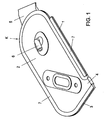
- Fig. 1 shows a support cushion for a vehicle seat, consisting of a folded Double film bubble, as an example of a fluidbe colllbaren body
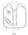
- Fig. 2 is a Representation of the film bubble of Fig. 1 in the unfolded state
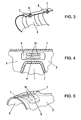
- Fig. 3 shows a detail of a curved connection channel between two portions of a body similar to FIG. 1 and 2
- Fig. 4 shows a detail of a connecting channel in the unfolded state
- Fig. 5 is an illustration of the connecting channel of FIG. 4 in a curved state, similar to the Fig. 3
- Figs. 6a and 6b show cross sections in the region of the connecting channel for a another embodiment of the body according to the invention.
- Fig. 1 shows a fluidbe sympatray invention, variable volume Body K, such as a lumbar bladder or similar support cushion for installation in vehicle seats, which body K consists of two superimposed, together along the encircling Edge-bonded, preferably welded foils, preferably made of plastic material, consists.
- the films form two superposed portions 2, 3 of the inflatable body K are folded, and wherein through the films at least one possibly the hinge region 1 crossing connecting channel 4 formed between the two sections 2, 3 of the fillable body K. is.
- the location of the subregions 2, 3 fix against each other.
- Via a fluid supply connection 6, preferably for compressed air is the upper portion 2 and further on the connecting channel 4 and the lower Part 3 of the body supplied and also emptied.
- connection of the superimposed films of the body K is shown in the Example accomplished by welding to form a circumferential weld bead 7, which also limits the connecting channel 4 laterally.
- This weld bead 7 is through formed the displacement of the material of the films.
- the connecting channel 4 is strongly curved, so due to the tensile stress in the outer foil and the compressive stress in the inner film they are pressed together with relatively high force.
- weld beads 7 at the edge of the connecting channel 4 increases in education the welding bead 7, the distance of the films to each other, and these films are immediate adjacent these weld beads 7 and thus over at least a portion of the width the connection channel 4 also kept spaced from each other, whereby the cross-sectional areas 8 of the connecting channel 4 in kinked or strongly curved State to be kept open.
- This also includes the fluid connection between the subregions 2, 3 of the body K always kept open.
- weld beads 7 may possibly become thicker be formed as necessary for secure connection of the superimposed films is. This can be accomplished by a suitable mold, also by overpressure between the two sheets to be joined during the welding process and something pronounced tool contour just before the welding edge, so that the films here the open Cross-sectional area 8 of the connecting channel 4 can form.
- FIG. 4 and 5 another embodiment is shown in which in the connecting channel 4 a piece of film 9 is used as a spacer.
- This spacer element 9 is inserted between the films forming the body K and may be conventional Way be fixed.
- the film piece 9 is in the longitudinal direction of the connecting channel 4 extending slots 10 to improve the flow through the connection channel 4 on.
- Fig. 6a is shown schematically in cross section a construction in which the film lying on the outside of the body (K) has a greater width than the bottom foil. This effect can be due to different material width from the beginning or also be caused by a pushing together during the welding process.
- the wider film forms at least one bulge 11 and thereby forms the even at kinking of the connection region of the partial areas 2, 3 of the body K held open Connection channel 4 off.
Landscapes
- Engineering & Computer Science (AREA)
- Mechanical Engineering (AREA)
- Aviation & Aerospace Engineering (AREA)
- Transportation (AREA)
- Lining Or Joining Of Plastics Or The Like (AREA)
- Tents Or Canopies (AREA)
- Mattresses And Other Support Structures For Chairs And Beds (AREA)
Applications Claiming Priority (2)
| Application Number | Priority Date | Filing Date | Title |
|---|---|---|---|
| AT1222004 | 2004-01-29 | ||
| AT0012204A AT412863B (de) | 2004-01-29 | 2004-01-29 | Fluidbefüllbarer, volumsveränderlicher körper |
Publications (3)
| Publication Number | Publication Date |
|---|---|
| EP1559611A2 true EP1559611A2 (fr) | 2005-08-03 |
| EP1559611A3 EP1559611A3 (fr) | 2009-05-06 |
| EP1559611B1 EP1559611B1 (fr) | 2012-01-04 |
Family
ID=33569152
Family Applications (1)
| Application Number | Title | Priority Date | Filing Date |
|---|---|---|---|
| EP05450010A Expired - Lifetime EP1559611B1 (fr) | 2004-01-29 | 2005-01-26 | Chambre pouvant être remplie de fluide, à volume variable |
Country Status (2)
| Country | Link |
|---|---|
| EP (1) | EP1559611B1 (fr) |
| AT (1) | AT412863B (fr) |
Cited By (2)
| Publication number | Priority date | Publication date | Assignee | Title |
|---|---|---|---|---|
| EP1752573A3 (fr) * | 2005-08-08 | 2007-06-06 | Greiner Purtec GmbH | Rembourrage pour siège de véhicule |
| EP3705348A1 (fr) | 2019-03-04 | 2020-09-09 | KA Group AG | Pile de cellules de massage pour un siège de véhicule |
Families Citing this family (1)
| Publication number | Priority date | Publication date | Assignee | Title |
|---|---|---|---|---|
| DE202015104103U1 (de) | 2015-08-05 | 2015-08-17 | Kongsberg Automotive Ab | Aufblasbares Stützkissen für einen Kraftfahrzeugsitz |
Citations (1)
| Publication number | Priority date | Publication date | Assignee | Title |
|---|---|---|---|---|
| DE20307633U1 (de) | 2003-05-15 | 2003-09-11 | S.E. Nündel Kunststofftechnik GmbH, 90530 Wendelstein | Stützkissen für einen Kraftfahrzeugsitz |
Family Cites Families (3)
| Publication number | Priority date | Publication date | Assignee | Title |
|---|---|---|---|---|
| JPH0513634Y2 (fr) * | 1989-04-28 | 1993-04-12 | ||
| AU6046896A (en) * | 1995-06-09 | 1997-01-09 | Herman Miller, Inc. | Office chair and adjustable lumbar support therefor |
| GB0102614D0 (en) * | 2001-02-02 | 2001-03-21 | Kirk Tim | An exercise device |
-
2004
- 2004-01-29 AT AT0012204A patent/AT412863B/de not_active IP Right Cessation
-
2005
- 2005-01-26 EP EP05450010A patent/EP1559611B1/fr not_active Expired - Lifetime
Patent Citations (1)
| Publication number | Priority date | Publication date | Assignee | Title |
|---|---|---|---|---|
| DE20307633U1 (de) | 2003-05-15 | 2003-09-11 | S.E. Nündel Kunststofftechnik GmbH, 90530 Wendelstein | Stützkissen für einen Kraftfahrzeugsitz |
Cited By (2)
| Publication number | Priority date | Publication date | Assignee | Title |
|---|---|---|---|---|
| EP1752573A3 (fr) * | 2005-08-08 | 2007-06-06 | Greiner Purtec GmbH | Rembourrage pour siège de véhicule |
| EP3705348A1 (fr) | 2019-03-04 | 2020-09-09 | KA Group AG | Pile de cellules de massage pour un siège de véhicule |
Also Published As
| Publication number | Publication date |
|---|---|
| AT412863B (de) | 2005-08-25 |
| ATA1222004A (de) | 2005-01-15 |
| EP1559611B1 (fr) | 2012-01-04 |
| EP1559611A3 (fr) | 2009-05-06 |
Similar Documents
| Publication | Publication Date | Title |
|---|---|---|
| AT502780B1 (de) | System zur automatischen verstellung der sitz-kontur sowie sitz, insbesondere fahrzeugsitz für automobile, flugzeuge oder dergleichen | |
| DE2519756C3 (de) | Wärmetauscher | |
| DE102015105371A1 (de) | Massagevorrichtung für einen Fahrzeugsitz | |
| DE102008051072A1 (de) | Kraftfahrzeugsitz mit Lendenstütze für ein Anti-Schleudertraumasystem | |
| DE102019214576B4 (de) | Fluidbefüllbares Blasensystem, Schweißwerkzeug und Verfahren zum Betrieb eines Schweißwerkzeugs | |
| DE2327301A1 (de) | Blattfeder | |
| DE102011089749A1 (de) | Fluidbefüllbare und volumenveränderliche Blase sowie Verfahren und Vorrichtung zum Herstellen einer solchen Blase | |
| WO2014057041A1 (fr) | Élément pneumatique | |
| DE202015104103U1 (de) | Aufblasbares Stützkissen für einen Kraftfahrzeugsitz | |
| DE2527255C3 (de) | Medizinische Membrandiffusionsvorrichtung | |
| DE102011109470A1 (de) | Stellelement und Verfahren zu dessen Herstellung | |
| DE102013213995A1 (de) | Rückenlehne für einen Fahrzeugsitz und Fahrzeugsitz | |
| DE102012112165A1 (de) | Hybride verbindungsstruktur eines dachrahmens | |
| EP3419737B1 (fr) | Élément filtrant, en particulier pour la filtration de gaz | |
| DE202012008758U1 (de) | Kraftfahrzeugsitzeinrichtung | |
| AT412863B (de) | Fluidbefüllbarer, volumsveränderlicher körper | |
| DE1034420B (de) | Gummi-Metall-Feder | |
| EP1698511A1 (fr) | Dispositif permettant de régler automatiquement le profil d'un siège, en particulier d'un siège | |
| DE102004010626A1 (de) | Blase für einen konturverstellbaren Sitz, insbesondere Fahrzeugsitz | |
| EP2016868A1 (fr) | Noyau pouvant être extrait pour matelas et coussins de meubles | |
| AT6794U2 (de) | Fluidbefüllbarer, volumsveränderlicher körper | |
| DE102022107079A1 (de) | Airbag und Fahrzeugsitzvorrichtung | |
| DE102016214529B4 (de) | Verfahren zur Herstellung einer mit Druckmittel befüllbaren Blase als Stellelement für einen Sitz | |
| DE202016105958U1 (de) | Expansionskörper als Verstellmittel in einem Kraftfahrzeugsitz sowie verstellbarer Kraftfahrzeugsitz | |
| DE102019134909A1 (de) | Hohlkammeranordnung |
Legal Events
| Date | Code | Title | Description |
|---|---|---|---|
| PUAI | Public reference made under article 153(3) epc to a published international application that has entered the european phase |
Free format text: ORIGINAL CODE: 0009012 |
|
| AK | Designated contracting states |
Kind code of ref document: A2 Designated state(s): AT BE BG CH CY CZ DE DK EE ES FI FR GB GR HU IE IS IT LI LT LU MC NL PL PT RO SE SI SK TR |
|
| AX | Request for extension of the european patent |
Extension state: AL BA HR LV MK YU |
|
| RAP1 | Party data changed (applicant data changed or rights of an application transferred) |
Owner name: HOERBIGER AUTOMATISIERUNGSTECHNIK HOLDING GMBH |
|
| PUAL | Search report despatched |
Free format text: ORIGINAL CODE: 0009013 |
|
| AK | Designated contracting states |
Kind code of ref document: A3 Designated state(s): AT BE BG CH CY CZ DE DK EE ES FI FR GB GR HU IE IS IT LI LT LU MC NL PL PT RO SE SI SK TR |
|
| AX | Request for extension of the european patent |
Extension state: AL BA HR LV MK YU |
|
| RIC1 | Information provided on ipc code assigned before grant |
Ipc: A47C 7/46 20060101ALI20090330BHEP Ipc: B60N 2/44 20060101AFI20050414BHEP |
|
| RAP1 | Party data changed (applicant data changed or rights of an application transferred) |
Owner name: HOERBIGER AUTOMOTIVE KOMFORTSYSTEME GMBH |
|
| 17Q | First examination report despatched |
Effective date: 20091006 |
|
| 17P | Request for examination filed |
Effective date: 20090820 |
|
| AKX | Designation fees paid |
Designated state(s): DE |
|
| GRAP | Despatch of communication of intention to grant a patent |
Free format text: ORIGINAL CODE: EPIDOSNIGR1 |
|
| GRAS | Grant fee paid |
Free format text: ORIGINAL CODE: EPIDOSNIGR3 |
|
| GRAA | (expected) grant |
Free format text: ORIGINAL CODE: 0009210 |
|
| AK | Designated contracting states |
Kind code of ref document: B1 Designated state(s): DE |
|
| REG | Reference to a national code |
Ref country code: DE Ref legal event code: R096 Ref document number: 502005012291 Country of ref document: DE Effective date: 20120301 |
|
| PLBE | No opposition filed within time limit |
Free format text: ORIGINAL CODE: 0009261 |
|
| STAA | Information on the status of an ep patent application or granted ep patent |
Free format text: STATUS: NO OPPOSITION FILED WITHIN TIME LIMIT |
|
| 26N | No opposition filed |
Effective date: 20121005 |
|
| REG | Reference to a national code |
Ref country code: DE Ref legal event code: R097 Ref document number: 502005012291 Country of ref document: DE Effective date: 20121005 |
|
| REG | Reference to a national code |
Ref country code: DE Ref legal event code: R079 Ref document number: 502005012291 Country of ref document: DE Free format text: PREVIOUS MAIN CLASS: B60N0002440000 Ipc: B60N0002900000 |
|
| PGFP | Annual fee paid to national office [announced via postgrant information from national office to epo] |
Ref country code: DE Payment date: 20231219 Year of fee payment: 20 |
|
| REG | Reference to a national code |
Ref country code: DE Ref legal event code: R071 Ref document number: 502005012291 Country of ref document: DE |