EP1559599B1 - Fahrzeugtür - Google Patents
Fahrzeugtür Download PDFInfo
- Publication number
- EP1559599B1 EP1559599B1 EP04027509A EP04027509A EP1559599B1 EP 1559599 B1 EP1559599 B1 EP 1559599B1 EP 04027509 A EP04027509 A EP 04027509A EP 04027509 A EP04027509 A EP 04027509A EP 1559599 B1 EP1559599 B1 EP 1559599B1
- Authority
- EP
- European Patent Office
- Prior art keywords
- vehicle door
- door
- support
- frame part
- reinforcement
- Prior art date
- Legal status (The legal status is an assumption and is not a legal conclusion. Google has not performed a legal analysis and makes no representation as to the accuracy of the status listed.)
- Expired - Lifetime
Links
Images


Classifications
-
- B—PERFORMING OPERATIONS; TRANSPORTING
- B60—VEHICLES IN GENERAL
- B60J—WINDOWS, WINDSCREENS, NON-FIXED ROOFS, DOORS, OR SIMILAR DEVICES FOR VEHICLES; REMOVABLE EXTERNAL PROTECTIVE COVERINGS SPECIALLY ADAPTED FOR VEHICLES
- B60J5/00—Doors
- B60J5/04—Doors arranged at the vehicle sides
- B60J5/042—Reinforcement elements
- B60J5/0422—Elongated type elements, e.g. beams, cables, belts or wires
- B60J5/0423—Elongated type elements, e.g. beams, cables, belts or wires characterised by position in the lower door structure
- B60J5/0425—Elongated type elements, e.g. beams, cables, belts or wires characterised by position in the lower door structure the elements being arranged essentially horizontal in the centre of the lower door structure
-
- B—PERFORMING OPERATIONS; TRANSPORTING
- B60—VEHICLES IN GENERAL
- B60J—WINDOWS, WINDSCREENS, NON-FIXED ROOFS, DOORS, OR SIMILAR DEVICES FOR VEHICLES; REMOVABLE EXTERNAL PROTECTIVE COVERINGS SPECIALLY ADAPTED FOR VEHICLES
- B60J5/00—Doors
- B60J5/04—Doors arranged at the vehicle sides
- B60J5/042—Reinforcement elements
- B60J5/0451—Block or short strip-type elements
Definitions
- the invention relates to a vehicle door with internal reinforcements according to the preamble of patent claim 1.
- a vehicle door which comprises a support structure in which reinforcing beams are arranged, which are connected to the frame of the door support structure.
- a door element with an internal reinforcing support known, which consists of an overhead belt, a belt below and a diagonal strut and connecting struts for the door.
- the object of the invention is to provide a vehicle door which is rigid in an area of the door closing device.
- the advantages achieved by the invention are to achieve a reduction in the vibration behavior of the door outer panel, so that a portion of the vehicle door is stiffened in a targeted manner and thus in a crash, the door can not jump alone, ie the locking mechanism of the vehicle door can be Do not open an impact from the outside on the door.
- the upper portion of the door, in which a closing latch of the locking device is arranged tries to move outwards in the opening direction of the door.
- a targeted force deflection in the event of a crash should take place through the reinforcement.
- the one internal reinforcement of the vehicle door consists of an angularly formed from two arm parts reinforcement carrier.
- the one arm of the reinforcing member is aligned in an approximately horizontal plane and with its free end on the rear door frame part and the other approximately aligned in a Schrägele arm part is fastened with its other turned off free end to an impact beam of the door.
- the area of the door is selectively stiffened surface, in which the trap receiving the locking device is arranged.
- the reinforcing support in cross-section is partially U-shaped profile and is connected to a web surface in sections on the inner door panel via a bond.
- the reinforcing support is connected with its free end of the approximately horizontally oriented arm part via a tab to the rear frame part of the vehicle door.
- a firm connection with the door frame is achieved by the reinforcing support is connected at its free end of the approximately obliquely oriented arm part via another tab with a leg of the impact beam.
- the angle-shaped reinforcing beam is connected to the impact beam and the rear frame part and forms a non-impact surface area of the door outer panel.
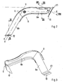
- a rear side vehicle door 1 of a motor vehicle comprises inter alia a door frame 2 with a front and a rear frame part 3, 4, with which an approximately horizontally oriented impact beam 5 is connected.
- an angle-shaped reinforcing support 6 is arranged in the door and connected to the impact beam 5 and the one frame part 4 and to the door outer panel 7.
- the angle-shaped reinforcement beam 6 comprises two arm parts 6a and 6b, wherein the one arm part 6a is arranged approximately in a horizontal plane X-X and the further arm part 6b is arranged at an obtuse angle ⁇ to the first arm part 6 in a slanted plane Y-Y.
- the arrangement of the reinforcing member 6 is spatially chosen so that a closing element S for the door - which is arranged in the frame part 4a as an opening 10 for a striker S1 to be inserted - is bounded.
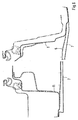
- the free ends E and E1 of the reinforcing member 6 with the impact beam 5 are firmly connected. Furthermore, the reinforcement beam 6 is firmly connected via an adhesive bond 11 or the like connection with the door outer panel 7 and is supported on this.
- the impact beam 5 is connected with its free ends with a door profile T, T1 or with the frame parts 3, 4 of the door frame, which is in Fig. 6 is shown in more detail. With this impact beam 5 is connected via tabs 12, 13 of the reinforcing member 6 on the one hand with the impact beam 5 and on the other hand with the frame part 4.
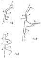
- the reinforcing beam 6 is fixedly connected via the bond 11 with the door outer panel 7. Furthermore, in Fig. 8 the connection of the reinforcing member 6 with the impact beam 5 via the tab 13 is shown. In Fig. 9 the connection of the reinforcing member 6 is shown with the impact beam 5 via the further tab 12.
- the reinforcing support 6 consists in cross section partially of a U-profile and is largely firmly connected over its length by means of a bond 11 with the door outer panel 7, which in Fig. 4 is shown in more detail. Also, the impact beam 5 is as in Fig. 1 and Fig. 9 shown, firmly connected via bonds 15 with the door outer panel 7.
Landscapes
- Engineering & Computer Science (AREA)
- Mechanical Engineering (AREA)
- Body Structure For Vehicles (AREA)
- Seal Device For Vehicle (AREA)
Description
- Die Erfindung bezieht sich auf eine Fahrzeugtür mit innenliegenden Verstärkungen nach dem Oberbegriff des Patentanspruchs 1.
- Aus der
DE 40 08 111 A1 ist eine Fahrzeugtür bekannt, die eine Tragstruktur umfasst, in welcher verstärkende Träger angeordnet sind, die mit dem Rahmen der Türtragstruktur verbunden sind. Aus derEP 1 086 840 A1 ist ein Türelement mit einem innenliegenden Verstärkungsträger bekannt, der aus einem oben liegenden Gurt, einem unten liegenden Gurt sowie einer Diagonalstrebe und Anbindungsstreben für die Tür besteht. - Die Aufgabe der Erfindung besteht darin, eine Fahrzeugtür zu schaffen, welche in einem Bereich der Tür-Schließeinrichtung steif ausgebildet ist.
- Diese Aufgabe wird erfindungsgemäß durch die Merkmale des Anspruchs 1 gelöst. Weitere vorteilhafte Merkmale beinhalten die Unteransprüche.
- Die mit der Erfindung hauptsächlich erzielten Vorteile bestehen darin, eine Reduzierung des Schwingungsverhaltens des Türaußenbleches zu erzielen, so dass ein Bereich der Fahrzeugtür in gezielter Weise versteift wird und somit bei einem Crashfall die Tür nicht alleine aufspringen kann, d.h. der Schließmechanismus der Fahrzeugtür kann sich bei einem von außen auf die Tür auftreffenden Stoß nicht öffnen. Durch diesen äußeren Stoß versucht sich der obere Bereich der Tür, in welcher eine Schließfalle der Schließeinrichtung angeordnet ist, nach außen in Öffnungsrichtung der Tür zu bewegen. Außerdem soll durch die Verstärkung eine gezielte Kraftumlenkung im Crashfall erfolgen.
- Um dieses zu vermeiden ist nach der Erfindung vorgesehen, dass die eine innenliegende Verstärkung der Fahrzeugtür aus einem winkelförmig aus zwei Armteilen gebildeten Verstärkungsträger besteht. Das eine Armteil des Verstärkungsträger ist in einer etwa horizontalen Ebene ausgerichtet und mit seinem freien Ende am hinteren Türrahmenteil und das weitere etwa in einer Schrägebene ausgerichtete Armteil ist mit seinem abgekehrten anderen freien Ende an einem Aufprallträger der Tür befestigt. Hierdurch wird in vorteilhafter Weise nach der Erfindung erreicht, dass der Bereich der Tür gezielt flächig versteift wird, in welcher die Fallenaufnahme der Schließeinrichtung angeordnet ist.
- Um eine wirksame Verstärkung der Fahrzeugtür und eine gewisse Beulfestigkeit des Außenbleches der Tür zu erreichen, ist nach der Erfindung des Weiteren vorgesehen, dass der Verstärkungsträger im Querschnitt teilweise U-profilförmig ausgebildet ist und mit einer Stegfläche abschnittsweise am Türinnenblech über eine Klebung verbunden wird. Insbesondere ist der Verstärkungsträger mit seinem freien Ende des etwa horizontal ausgerichteten Armteils über eine Lasche mit dem hinteren Rahmenteil der Fahrzeugtür verbunden. Eine feste Verbindung mit dem Türrahmen wird erreicht, indem der Verstärkungsträger mit seinem freien Ende des etwa schräg ausgerichteten Armteils über eine weitere Lasche mit einem Schenkel des Aufprallträgers verbunden wird. Der winkelförmige Verstärkungsträger ist mit dem Aufprallträger und dem hinteren Rahmenteil verbunden und bildet einen beulsicheren Flächenbereich des Türaußenbleches.
- Ein Ausführungsbeispiel der Erfindung ist in den Zeichnungen dargestellt und wird im folgenden näher beschrieben.
- Es zeigen
- Fig. 1
- eine Ansicht auf eine Innenseite einer Fahrzeugtür mit Verstärkungen,
- Fig. 2
- eine Ansicht auf eine winkelförmige Verstärkung,
- Fig. 3
- eine schaubildliche Darstellung der winkelförmigen Verstärkung,
- Fig. 4
- die beiden Verstärkungen in einer schaubildlichen Darstellung,
- Fig. 5
- einen Schnitt durch die Fahrzeugtür nach der Linie V-V der
Fig. 1 , - Fig. 6
- einen Schnitt durch die Fahrzeugtür nach der Linie VI-VI der
Fig. 1 , - Fig. 7
- einen Schnitt durch die Fahrzeugtür nach der Linie VII-VII der
Fig. 1 , - Fig. 8
- einen Schnitt durch die Fahrzeugtür nach der Linie VIII-VIII der
Fig. 1 und - Fig. 9
- einen Schnitt durch die Fahrzeugtür nach der Linie IX-IX der
Fig. 1 . - Eine hintere seitliche Fahrzeugtür 1 eines Kraftfahrzeuges umfasst unter anderem einen Türrahmen 2 mit einem vorderen und einem hinteren Rahmenteil 3, 4, mit denen ein etwa horizontal ausgerichteter Aufprallträger 5 verbunden ist. Zusätzlich zu diesem Aufprallträger 5 ist ein winkelförmig ausgeführter Verstärkungsträger 6 in der Tür angeordnet und mit dem Aufprallträger 5 und dem einen Rahmenteil 4 sowie mit dem Türaußenblech 7 verbunden.
- Der winkelförmige Verstärkungsträger 6 umfasst zwei Armteile 6a und 6b, wobei das eine Armteil 6a etwa in einer horizontalen Ebene X-X und das weitere Armteil 6b unter einem stumpfen Winkel α zum ersten Armteil 6 in einer Schrägebene Y-Y angeordnet ist.
- Die Anordnung des Verstärkungsträgers 6 ist räumlich so gewählt, dass ein Schließelement S für die Tür - welches im Rahmenteil 4a als Öffnung 10 für einen einzuführenden Schließbügel S1 angeordnet ist - umgrenzt wird.
- Zur Erzielung eines steifen Verbundes in der Tür 1 sind die freien Enden E und E1 des Verstärkungsträgers 6 mit dem Aufprallträger 5 fest verbunden. Des Weiteren ist der Verstärkungsträger 6 über eine Klebung 11 oder dergleichen Verbindung mit dem Türaußenblech 7 fest verbunden und stützt sich an diesem ab.
- Der Aufprallträger 5 ist mit seinen freien Enden mit einem Türprofil T, T1 oder mit den Rahmenteilen 3, 4 des Türrahmens verbunden, was in
Fig. 6 näher dargestellt ist. Mit diesem Aufprallträger 5 ist über Laschen 12, 13 der Verstärkungsträger 6 einerseits mit dem Aufprallträger 5 und andererseits mit dem Rahmenteil 4 verbunden. - Wie in
Fig. 7 näher dargestellt ist, wird der Verstärkungsträger 6 über die Klebung 11 mit dem Türaußenblech 7 fest verbunden. Des Weiteren ist inFig. 8 die Verbindung des Verstärkungsträgers 6 mit dem Aufprallträger 5 über die Lasche 13 dargestellt. InFig. 9 ist die Verbindung des Verstärkungsträgers 6 mit dem Aufprallträger 5 über die weitere Lasche 12 gezeigt. - Der Verstärkungsträger 6 besteht im Querschnitt teilweise aus einem U-Profil und ist über seine Länge größtenteils mittels einer Klebung 11 mit dem Türaußenblech 7 fest verbunden, was in
Fig. 4 näher dargestellt ist. Ebenfalls ist der Aufprallträger 5, wie inFig. 1 undFig. 9 gezeigt, über Klebungen 15 mit dem Türaußenblech 7 fest verbunden.
Claims (5)
- Fahrzeugtür mit innenliegenden Verstärkungen, die zwischen einem hinteren und einem vorderen Rahmenteil einer Tragstruktur der Fahrzeugtür angeordnet wird und eine von den innenliegenden Verstärkungen aus einem Arme aufweisenden Verstärkungsträger besteht, dadurch gekennzeichnet, dass der Verstärkungsträger (6) winkelförmig aus zwei Armteilen gebildet ist, wobei das eine Armteil (6a) in einer etwa horizontalen Ebene (X-X) ausgerichtet ist und mit seinem freien Ende (E1) am hinteren Tür-Rahmenteil (4) und das weitere etwa in einer Schrägebene (Y-Y) ausgerichtete Armteil (6b) mit seinem abgekehrten anderen freien Ende (E) an einem Aufprallträger (5) der Tür (1) befestigt ist, der mit dem hinteren und vorderen Rahmenteil (3, 4) fest verbunden wird und zwischen dem Aufprallträger (5) und den Armteilen (6a, 6b) des Verstärkungsträgers (6) ein Schließelement (S, S1) der Fahrzeugtür (1) im hinteren Tür-Rahmenteil (4) angeordnet ist.
- Fahrzeugtür nach Anspruch 1, dadurch gekennzeichnet, dass der Verstärkungsträger (6) im Querschnitt teilweise U-profilförmig ausgebildet ist und mit einer Stegfläche (6c) abschnittsweise am Türinnenblech (7) über eine Klebung (11) verbindbar ist.
- Fahrzeugtür nach den Ansprüchen 1 oder 2, dadurch gekennzeichnet, dass der Verstärkungsträger (6) mit seinem einen freien Ende (E1) des etwa horizontal ausgerichteten Armteils (6a) über eine Lasche (13) mit dem hinteren Rahmenteil (4) der Fahrzeugtür (1) verbunden ist.
- Fahrzeugtür nach den Ansprüchen 1, 2 oder 3, dadurch gekennzeichnet, dass der Verstärkungsträger (6) mit seinem anderen freien Ende (E1) des schräg ausgerichteten Armteils (6b) über eine weitere Lasche (12) mit einem Schenkel des Aufprallträgers (5) verbindbar ist.
- Fahrzeugtür nach einem der vorhergehenden Ansprüche, dadurch gekennzeichnet, dass der winkelförmige Verstärkungsträger (6) mit dem Aufprallträger (5) und dem hinteren Rahmenteil (4) der Fahrzeugtür einen beulsicheren Flächenbereich (F) der Fahrzeugtür (1) bildet.
Applications Claiming Priority (2)
| Application Number | Priority Date | Filing Date | Title |
|---|---|---|---|
| DE102004004377 | 2004-01-29 | ||
| DE102004004377A DE102004004377A1 (de) | 2004-01-29 | 2004-01-29 | Fahrzeugtür |
Publications (2)
| Publication Number | Publication Date |
|---|---|
| EP1559599A1 EP1559599A1 (de) | 2005-08-03 |
| EP1559599B1 true EP1559599B1 (de) | 2008-02-13 |
Family
ID=34638792
Family Applications (1)
| Application Number | Title | Priority Date | Filing Date |
|---|---|---|---|
| EP04027509A Expired - Lifetime EP1559599B1 (de) | 2004-01-29 | 2004-11-19 | Fahrzeugtür |
Country Status (4)
| Country | Link |
|---|---|
| EP (1) | EP1559599B1 (de) |
| AT (1) | ATE385921T1 (de) |
| DE (2) | DE102004004377A1 (de) |
| ES (1) | ES2298669T3 (de) |
Families Citing this family (2)
| Publication number | Priority date | Publication date | Assignee | Title |
|---|---|---|---|---|
| DE102008063027B4 (de) | 2008-12-23 | 2023-06-15 | Dr. Ing. H.C. F. Porsche Aktiengesellschaft | Kraftfahrzeugtür |
| DE102014207060B4 (de) | 2013-04-17 | 2021-07-01 | Volkswagen Aktiengesellschaft | Fahrzeugtür mit einem Aufprallträger sowie Kraftfahrzeug mit einer derartigen Fahrzeugtür |
Family Cites Families (8)
| Publication number | Priority date | Publication date | Assignee | Title |
|---|---|---|---|---|
| DE4008111A1 (de) | 1990-03-14 | 1991-09-19 | Audi Ag | Fahrzeugtuere |
| ES1015300Y (es) * | 1990-10-02 | 1992-01-01 | Aplicaciones Industriales De Cromo Duro, S.A. | Apoyacodos perfeccionado. |
| DE4236229A1 (de) * | 1992-10-27 | 1994-04-28 | Daimler Benz Ag | Kraftfahrzeugtür |
| US6135537A (en) * | 1997-12-22 | 2000-10-24 | Chrysler Corporation | Reinforced vehicle door assembly |
| FR2783758B1 (fr) * | 1998-09-24 | 2000-12-15 | Peugeot | Dispositif formant renfort de porte pour vehicule automobile |
| EP1086840A1 (de) * | 1999-09-21 | 2001-03-28 | Iso Service S.r.l. | Tür für Motorfahrzeug |
| DE10048124A1 (de) * | 2000-09-28 | 2002-04-18 | Porsche Ag | Tür für ein Kraftfahrzeug |
| JP4385582B2 (ja) * | 2002-10-01 | 2009-12-16 | マツダ株式会社 | 車両のサイドドア構造 |
-
2004
- 2004-01-29 DE DE102004004377A patent/DE102004004377A1/de not_active Ceased
- 2004-11-19 ES ES04027509T patent/ES2298669T3/es not_active Expired - Lifetime
- 2004-11-19 AT AT04027509T patent/ATE385921T1/de active
- 2004-11-19 EP EP04027509A patent/EP1559599B1/de not_active Expired - Lifetime
- 2004-11-19 DE DE502004006186T patent/DE502004006186D1/de not_active Expired - Lifetime
Also Published As
| Publication number | Publication date |
|---|---|
| ATE385921T1 (de) | 2008-03-15 |
| DE102004004377A1 (de) | 2005-08-18 |
| EP1559599A1 (de) | 2005-08-03 |
| ES2298669T3 (es) | 2008-05-16 |
| DE502004006186D1 (de) | 2008-03-27 |
Similar Documents
| Publication | Publication Date | Title |
|---|---|---|
| EP1525132B1 (de) | Bodenträgeranordnung an kraftfahrzeugen | |
| DE19531957C2 (de) | Karosseriestruktur für ein Kraftfahrzeug | |
| EP0454942B1 (de) | Wagenkasten, insbesondere für Personenkraftwagen | |
| DE10038389B4 (de) | Motorhaubenstruktur für ein Fahrzeug | |
| EP1027223B1 (de) | Integrale türinnenverstärkung | |
| DE102008047463B4 (de) | Fahrzeugtür | |
| DE10244621B4 (de) | Frontsäulenverstärkungsaufbau eines Fahrzeugs | |
| DE102011112197B4 (de) | Struktur eines Trennwandseitenelements in Fahrzeugen | |
| DE102005029255B4 (de) | Schwelleranordnung für ein Fahrzeug | |
| DE102016209186B3 (de) | Karosseriestruktur für ein Kraftfahrzeug | |
| EP3959117B1 (de) | Karosserie-vorbaustruktur für ein fahrzeug | |
| EP2357120B1 (de) | Tragstruktur einer Fahrzeugkarosserie im schwellerseitigen Bereich einer C-Säule | |
| DE10047880A1 (de) | Fahrschemelkonstruktion | |
| DE102007011719A1 (de) | Verstärkungsanordnung im Bereich einer vorderen Türsäule einer Kraftwagenkarosserie | |
| DE10232842A1 (de) | Bodenversteifungsstruktur an Kraftfahrzeugen | |
| EP1510384B1 (de) | Aufprallschutzvorrichtung für eine Tür eines Kraftfahrzeugs | |
| EP1586495B1 (de) | Aufbaustruktur eines Personenkraftwagens insbesondere eines Cabriolets | |
| DE102018004380B4 (de) | Verstärkungsteil | |
| EP1559599B1 (de) | Fahrzeugtür | |
| EP1600338B1 (de) | Kraftfahrzeug mit einem Energie absorbierenden Deformationselement | |
| EP1488986B1 (de) | Kraftfahrzeug mit einer Verbindungsanordnung im Dachbereich | |
| DE102005061295B4 (de) | Türstruktur | |
| DE10254108B4 (de) | Abnehmbares Dach für ein Kraftfahrzeug | |
| DE102006015403A1 (de) | Fronthaube für einen Personenkraftwagen | |
| EP2221203B1 (de) | Faltverdeck für einen Personenkraftwagen |
Legal Events
| Date | Code | Title | Description |
|---|---|---|---|
| PUAI | Public reference made under article 153(3) epc to a published international application that has entered the european phase |
Free format text: ORIGINAL CODE: 0009012 |
|
| AK | Designated contracting states |
Kind code of ref document: A1 Designated state(s): AT BE BG CH CY CZ DE DK EE ES FI FR GB GR HU IE IS IT LI LU MC NL PL PT RO SE SI SK TR |
|
| AX | Request for extension of the european patent |
Extension state: AL HR LT LV MK YU |
|
| 17P | Request for examination filed |
Effective date: 20060203 |
|
| AKX | Designation fees paid |
Designated state(s): AT DE ES FR GB IT |
|
| GRAP | Despatch of communication of intention to grant a patent |
Free format text: ORIGINAL CODE: EPIDOSNIGR1 |
|
| GRAS | Grant fee paid |
Free format text: ORIGINAL CODE: EPIDOSNIGR3 |
|
| GRAA | (expected) grant |
Free format text: ORIGINAL CODE: 0009210 |
|
| AK | Designated contracting states |
Kind code of ref document: B1 Designated state(s): AT DE ES FR GB IT |
|
| REG | Reference to a national code |
Ref country code: GB Ref legal event code: FG4D Free format text: NOT ENGLISH |
|
| REF | Corresponds to: |
Ref document number: 502004006186 Country of ref document: DE Date of ref document: 20080327 Kind code of ref document: P |
|
| GBT | Gb: translation of ep patent filed (gb section 77(6)(a)/1977) |
Effective date: 20080415 |
|
| RAP2 | Party data changed (patent owner data changed or rights of a patent transferred) |
Owner name: DR. ING. H.C. F. PORSCHE AKTIENGESELLSCHAFT |
|
| REG | Reference to a national code |
Ref country code: ES Ref legal event code: FG2A Ref document number: 2298669 Country of ref document: ES Kind code of ref document: T3 |
|
| RAP2 | Party data changed (patent owner data changed or rights of a patent transferred) |
Owner name: DR. ING. H.C. F. PORSCHE AKTIENGESELLSCHAFT |
|
| ET | Fr: translation filed | ||
| PLBE | No opposition filed within time limit |
Free format text: ORIGINAL CODE: 0009261 |
|
| STAA | Information on the status of an ep patent application or granted ep patent |
Free format text: STATUS: NO OPPOSITION FILED WITHIN TIME LIMIT |
|
| 26N | No opposition filed |
Effective date: 20081114 |
|
| REG | Reference to a national code |
Ref country code: FR Ref legal event code: TP |
|
| REG | Reference to a national code |
Ref country code: FR Ref legal event code: CD |
|
| REG | Reference to a national code |
Ref country code: ES Ref legal event code: FD2A Effective date: 20081120 |
|
| PG25 | Lapsed in a contracting state [announced via postgrant information from national office to epo] |
Ref country code: ES Free format text: LAPSE BECAUSE OF NON-PAYMENT OF DUE FEES Effective date: 20081120 |
|
| REG | Reference to a national code |
Ref country code: FR Ref legal event code: TP |
|
| REG | Reference to a national code |
Ref country code: GB Ref legal event code: 732E Free format text: REGISTERED BETWEEN 20110310 AND 20110316 |
|
| REG | Reference to a national code |
Ref country code: GB Ref legal event code: 732E Free format text: REGISTERED BETWEEN 20110331 AND 20110406 |
|
| REG | Reference to a national code |
Ref country code: FR Ref legal event code: PLFP Year of fee payment: 12 |
|
| REG | Reference to a national code |
Ref country code: FR Ref legal event code: PLFP Year of fee payment: 13 |
|
| REG | Reference to a national code |
Ref country code: FR Ref legal event code: PLFP Year of fee payment: 14 |
|
| PGFP | Annual fee paid to national office [announced via postgrant information from national office to epo] |
Ref country code: AT Payment date: 20171121 Year of fee payment: 14 Ref country code: IT Payment date: 20171124 Year of fee payment: 14 |
|
| PGFP | Annual fee paid to national office [announced via postgrant information from national office to epo] |
Ref country code: FR Payment date: 20181123 Year of fee payment: 15 Ref country code: GB Payment date: 20181120 Year of fee payment: 15 |
|
| REG | Reference to a national code |
Ref country code: AT Ref legal event code: MM01 Ref document number: 385921 Country of ref document: AT Kind code of ref document: T Effective date: 20181119 |
|
| PG25 | Lapsed in a contracting state [announced via postgrant information from national office to epo] |
Ref country code: IT Free format text: LAPSE BECAUSE OF NON-PAYMENT OF DUE FEES Effective date: 20181119 Ref country code: AT Free format text: LAPSE BECAUSE OF NON-PAYMENT OF DUE FEES Effective date: 20181119 |
|
| PGFP | Annual fee paid to national office [announced via postgrant information from national office to epo] |
Ref country code: DE Payment date: 20191024 Year of fee payment: 16 |
|
| GBPC | Gb: european patent ceased through non-payment of renewal fee |
Effective date: 20191119 |
|
| PG25 | Lapsed in a contracting state [announced via postgrant information from national office to epo] |
Ref country code: GB Free format text: LAPSE BECAUSE OF NON-PAYMENT OF DUE FEES Effective date: 20191119 Ref country code: FR Free format text: LAPSE BECAUSE OF NON-PAYMENT OF DUE FEES Effective date: 20191130 |
|
| REG | Reference to a national code |
Ref country code: DE Ref legal event code: R119 Ref document number: 502004006186 Country of ref document: DE |
|
| PG25 | Lapsed in a contracting state [announced via postgrant information from national office to epo] |
Ref country code: DE Free format text: LAPSE BECAUSE OF NON-PAYMENT OF DUE FEES Effective date: 20210601 |