EP1559506B1 - Vorrichtung zum Schleifen der Kanten von Skiern oder Snowboards - Google Patents
Vorrichtung zum Schleifen der Kanten von Skiern oder Snowboards Download PDFInfo
- Publication number
- EP1559506B1 EP1559506B1 EP04425179A EP04425179A EP1559506B1 EP 1559506 B1 EP1559506 B1 EP 1559506B1 EP 04425179 A EP04425179 A EP 04425179A EP 04425179 A EP04425179 A EP 04425179A EP 1559506 B1 EP1559506 B1 EP 1559506B1
- Authority
- EP
- European Patent Office
- Prior art keywords
- ski
- axis
- grinding wheel
- blade
- motor
- Prior art date
- Legal status (The legal status is an assumption and is not a legal conclusion. Google has not performed a legal analysis and makes no representation as to the accuracy of the status listed.)
- Expired - Lifetime
Links
- 230000010355 oscillation Effects 0.000 claims abstract description 5
- 230000008878 coupling Effects 0.000 claims description 3
- 238000010168 coupling process Methods 0.000 claims description 3
- 238000005859 coupling reaction Methods 0.000 claims description 3
- 230000001747 exhibiting effect Effects 0.000 claims 2
- 238000000034 method Methods 0.000 description 9
- 230000000284 resting effect Effects 0.000 description 4
- 230000006978 adaptation Effects 0.000 description 1
- 238000007792 addition Methods 0.000 description 1
- 230000002452 interceptive effect Effects 0.000 description 1
Images


Classifications
-
- B—PERFORMING OPERATIONS; TRANSPORTING
- B24—GRINDING; POLISHING
- B24B—MACHINES, DEVICES, OR PROCESSES FOR GRINDING OR POLISHING; DRESSING OR CONDITIONING OF ABRADING SURFACES; FEEDING OF GRINDING, POLISHING, OR LAPPING AGENTS
- B24B3/00—Sharpening cutting edges, e.g. of tools; Accessories therefor, e.g. for holding the tools
- B24B3/006—Sharpening cutting edges, e.g. of tools; Accessories therefor, e.g. for holding the tools for edges of skis, snowboards or the like
-
- A—HUMAN NECESSITIES
- A63—SPORTS; GAMES; AMUSEMENTS
- A63C—SKATES; SKIS; ROLLER SKATES; DESIGN OR LAYOUT OF COURTS, RINKS OR THE LIKE
- A63C11/00—Accessories for skiing or snowboarding
- A63C11/04—Accessories for skiing or snowboarding for treating skis or snowboards
- A63C11/06—Edge-sharpeners
Definitions
- the subject of the present invention is a device for processing or finishing the blades of a ski, a snowboard or the like.
- the present invention relates to a device adapted for finishing the side surface and the sliding surface of both blades of a ski by a grinding wheel.
- a device for processing the blades of a ski fitted on a machine adapted for receiving the ski and automatically carrying out the blade finishing operation. More precisely, there are provided two devices for processing the ski blades, arranged at opposed sides with respect to the longitudinal ski development. The ski is inserted into a seat of the machine and, by moving the ski itself along its longitudinal axis or moving the above devices along a direction parallel to the longitudinal ski axis, a relative translation motion is obtained between the ski and the devices in question, which allows processing the entire blade length.
- the ski shape has brought to favour the so-called shaped skis, that is, wherein the width in the direction perpendicular to the longitudinal ski length varies along the longitudinal development itself.
- the ski exhibits enlarged portions at the tip and at the tail whereas the central portion of the ski exhibits a smaller width. Consequently, the side blade surface exhibits a curvilinear outline relative to the longitudinal ski axis, which known devices are not always capable of finishing. Consequently, the ski is not capable of ensuring optimum performance in terms of speed and blade grip of the snow mantle, for example icy.
- the known devices are easily stuck along the side blade surface, thereby creating an inaccurate finishing with consequent reduced performance during the use of the skis, especially during competitions.
- the problem at the basis of the present invention is that of proposing a device for processing the blades of a ski, which should exhibit such structural and functional features as to meet the above need and overcoming the disadvantages mentioned with reference to the prior art.
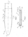
- figure 1 shows a bottom view of a ski, that is, a view showing the sliding surface of the ski, adapted for resting on the ground during the normal use of the ski itself;
- figure 2 shows the section II-II of the ski of figure 1 , corresponding to the position in which the ski is during its normal condition of use turned by 180°;
- figure 3a shows an enlarged view of the detail III of figure 2 according to a first embodiment
- figure 3b shows an enlarged view of the detail III of figure 2 according to a second embodiment
- FIGS. 4a-4d schematically show a top view of a ski and of a portion of a device for processing the blades of a ski according to the present invention in different operating conditions;
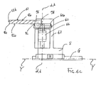
- figure 5 shows a side view of the device shown in figure 4d according to arrow V of figure 4d ;
- FIGS. 6a-6c schematically show a side view of a portion of the device for processing the blades of a ski according to the present invention in different operating conditions
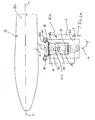
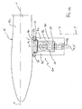
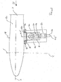
- figure 7 show a substantially top view of a possible embodiment of the device for processing the blades of a ski according to the present invention
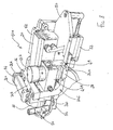
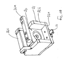
- figure 8 shows a perspective view of the device of figure 7 according to arrow VIII;
- figure 9 shows a perspective view of the device of figure 7 according to arrow IX;
- figure 10 shows a perspective view of a detail of a portion of the device according to the present invention.
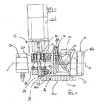
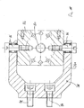
- figure 11 shows a vertical section view according to a possible embodiment
- figure 12 shows a vertical section view according to a possible embodiment
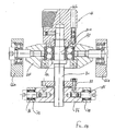
- FIGS. 13 and 14 show a portion of the section of figure 11 or 12 in different operating conditions
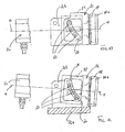
- figure 15 shows a side view of a portion of the device according to the present invention adapted for processing a sliding surface of a ski blade
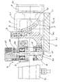
- figure 16 shows section XVI-XVI of figure 15 ;
- figure 17 shows section XVII-XVII of figure 15 ;
- figure 18 shows a perspective view of a detail of a first portion of the device according to the present invention
- figure 19 shows a perspective view of a detail of the device according to the present invention.
- figure 20 shows a perspective partly sectioned view of a ski wherein there is highlighted the abrasive ring of the front grinding wheel adapted for processing the sliding surface of the blade.
- reference numeral 10 globally indicates a device for processing the blades of a ski 12.
- figure 1 there is schematically illustrated a portion of a ski 12, according to a bottom view with reference to the normal use of the ski itself.
- figure 1 shows a view wherein there is shown the sliding surface of the ski, indicated with reference numeral 12a. More in detail, figure 1 shows a bottom view of the tip portion of a ski wherein there is highlighted the ski blade, indicated with reference numeral 14.
- the lower surface of the blade shown in figure 1 and corresponding to the sliding surface of the ski is indicated with reference numeral 14a.
- the blade surface indicated with reference numeral 14a will also be referred to as sliding surface.
- Ski 12 conventionally develops along a longitudinal axis X-X and, as shown in figure 1 , ski 12 exhibits a variable length L along the longitudinal development of the ski itself.
- the variation of width L is generally such that the ski exhibits a larger width in portions close to the tip and to the tail compared to a central portion of the ski itself.
- Figure 2 schematically shows section II-II of figure 1 .
- Reference numeral 12b indicates the side surfaces of the ski and reference numeral 14b indicates the side surfaces of the blades.
- reference numeral 12c indicates the visible surface of the ski, that is, the surface that during the normal use of the ski is arranged on top, contrary to what shown in figure 2 .
- Figures 3a and 3b are two enlarged views of two different embodiments of the detail indicated with III in figure 2 .
- Figure 3a shows a conventional embodiment of ski 12, wherein the sliding surface 14a of the blade and the sliding surface 12a of the ski substantially lay on the same plane, provided there are no inclination of the blade surface (indicated with a broken line).
- Figure 3b shows a new and advantageous embodiment of the ski, wherein the sliding surface 14a of the blade is lowered compared to the sliding surface 12a of the ski.
- the sliding surface 14a is arranged below the sliding surface 12a of the ski (with reference to the normal use of the ski wherein the sliding surface 12a of the ski rests on the ground, the sliding surface 14a of the blade is on top of the sliding surface 12a of the ski, the ski being rotated by 180° compared to figure 3b ).
- a lower outside edge of the blade is indicated with reference numeral 15a whereas an upper outside edge of the blade is indicated with reference numeral 15b.
- the advantageous embodiment of the ski (or of a snowboard) according to what illustrated in figure 3b provides for the lowering of the blade relative to the so-called ski base.
- the base processing is easier since it is possible to properly process also its edges, thanks to the presence of step 16.
- the ski or snowboard performance is improved, both in terms of grip and in terms of speed reached.
- the device 10 object of the present invention preferably is part of a machine adapted for receiving the ski and automatically processing the sliding surfaces 14a and the side surfaces 14b of blades 14.
- Figure 7 shows a top view of a portion of the machine housing ski 12 and a device 10. At the side opposed to axis X-X there is provided another device, specular to that shown in figure 7 , not shown.
- the ski may be inserted into the machine with the blades arranged on top or at the bottom according to the arrangement of device 10 onto the machine itself.
- the ski is inserted into the machine so that the sliding surface 12a is horizontal and arranged at the bottom, that is, as in the normal use of the ski.
- the ski is inserted into a seat, not shown, wherein it is held still with devices 10 arranged at opposed sides of the ski.
- Each device 10 is made to move according to a direction parallel to the longitudinal development X-X of the ski itself.
- the movement of device 10 according to the direction of axis X-X be of the controlled type with feedback, so that the movement axis of device 10 parallel to the longitudinal axis X-X of the ski is a controlled axis of the machine.
- the ski is seated onto rollers, not shown, and moved along the direction of its longitudinal axis X-X relative to devices 10. Also in this case, it is preferable that a controlled machine axis corresponds to the ski movement along its longitudinal axis X-X.
- the machine is structurally and functionally adapted for realising a relative motion between devices 10 arranged at opposed sides of the ski and the ski itself, so that each device 10 may process the ski blade along all of its longitudinal extension.
- a relative motion is provided between a device 10 and ski 12 that develops along the longitudinal axis X-X of the ski itself.
- device 10 is supported on the receiving machine in a substantially conventional manner, based on whether the ski or the device itself moves.
- device 10 comprises a support element S operatively associated to linear guides G.
- the support element S can move along guides G defining a movement axis Y-Y, relative to the machine that seats the ski, arranged transversally to axis X-X of the ski itself.
- axis Y-Y along which the support element S moves is perpendicular to the ski development axis X-X.
- axis Y-Y is preferably substantially parallel to the sliding surface 12a of the ski.
- axis Y-Y is a horizontal movement axis arranged perpendicularly to the ski development axis X-X.
- the term "horizontal” or “vertical” is used with reference to the above condition of the ski on the machine.
- an actuator A for example a pneumatic cylinder, is arranged between the support element S and the machine structure for carrying out a movement for moving device 10 next to the ski along axis Y-Y.
- device 10 comprises a first portion 10a adapted for processing the side surface 14b of the blade.
- the first portion 10a is schematically illustrated in figures 4a-4d and 5 , whereas figures 7-10 show a possible embodiment.
- the first portion 10a comprises a first grinding wheel 18, or side grinding wheel, preferably of the cup grinding wheel type, wherein the abrasive surface consists of a ring 18a.
- the abrasive ring 18a is flat and substantially perpendicular to an axis of rotation a-a of the grinding wheel.
- side grinding wheel refers to a grinding wheel adapted for processing the side surface 14b of the blade.
- the first grinding wheel 18 is operatively associated to a motor 20 adapted for driving it into rotation around an axis of rotation a-a.
- the axis of rotation a-a of the first grinding wheel 18 can vary its inclination relative to a horizontal plane.
- the surface to be processed is a side surface of the blade perpendicular to the sliding surface of the ski
- the axis of rotation a-a is adapted for being arranged in a plane substantially parallel to the sliding surface 12a of the ski, that is, in the general case in which the ski is arranged so that its sliding surface 12a is horizontal, axis a-a is arranged in a substantially horizontal plane.
- the axis of rotation a-a is adapted for being arranged slightly inclined relative to the horizontal plane.
- the inclination of axis a-a can be comprised between -3 and +6 sexagesimal degrees, for example between -1 and 5 sexagesimal degrees or in the range of 0-5 sexagesimal degrees, as it will be described hereinafter.
- axis a-a can move relative to direction Y-Y following the curvilinear development of the side surface 12b of the ski, as better described hereinafter.
- motor 20 comprises a casing 22 shaped as a box, or grinding wheel holder spindle.
- motor 20 is housed into a front carriage (with reference to the ski) indicated with reference numeral 24.
- the front carriage 24 is operatively associated to a guide 26 on which it can be made to move along an axis Y'-Y' arranged on the machine whereon the ski is seated so as to be substantially in the same direction as axis Y-Y, unless provided there are no oscillations, which will be described hereinafter.
- Axis Y'-Y' along which the front carriage 24 moves is perpendicular to the portion of the side surface of the ski or of the blade that directly faces the first grinding wheel 18 during the processing of the blade itself.
- axis Y'-Y' is preferably substantially parallel to the sliding surface 12a of the ski.
- axis Y'-Y' is a horizontal movement axis arranged perpendicularly to the portion of the side surface of the ski or of the blade facing directly the first grinding wheel 18 during the processing of the blade itself.
- axis Y'-Y' and axis a-a lay in the same vertical plane.
- the front carriage 24 is schematised in figures 4a-4d and 5 to schematically show the operation of device 10 as described below.
- figure 4a some details are outlined because they are not directly visible whereas in the following figures, the elements have been left in continuous line for simplicity of representation.
- the support element S is shown only in figure 4a and 5 by way of an example.
- the front carriage 24 comprises a lower base 24a, slidingly engaged on guide 26, and containment walls 24b, for example connected by a traverse 24c so as to define a seat adapted for receiving the box-shaped casing 22 of motor 20.
- the front carriage 24 may have any other shape besides that just described.
- motor 20 and therefore the first grinding wheel 18 are fitted on the front carriage 24 so as to rotate around an axis b-b such as to change the inclination of the abrasive ring 18a of the first grinding wheel relative to the side surface of the blade.
- Axis b-b is perpendicular to axis a-a and lays in a horizontal plane.
- the above means for changing the inclination of axis a-a are structured so that axis b-b lays on a chord of the grinding wheel adapted for coming into contact with the lower outside edge 15a of the blade.
- axis a-a is inclined by making it rotate around axis b-b which coincides with the free edge or corner of the blade ( figure 20 ).
- the blade corner as fulcrum for adjusting the inclination of the grinding wheel (axis a-a)
- the ski blade processing can therefore be made automated, controlled and with feedback.
- the inclination of axis a-a of the grinding wheel that is, the adjustment of the blade surface inclination to be obtained, is advantageously realised by rotation around a known fulcrum, that is, by rotation around an axis that can advantageously be a controlled processing axis, for example to be changed with substantial continuity based on the ski area (tip, centre or tail) being processed.
- the grinding wheel inclination adjustment, and therefore of the surface to be obtained occurs while the grinding wheel is in contact with the blade and along an interpolation portion between the different ski areas that can require different blade angles (tip, centre, and tail), also allowing a numerical control application of the process itself.
- motor 20 or more preferably its grinding wheel support spindle or casing 22, exhibit at least one arched slot 28, preferably two arched slots obtained on opposed surfaces of the motor, or of the box-shaped casing, which develop along an arched line 30 laying in a vertical plane.
- arched slot 28 preferably two arched slots obtained on opposed surfaces of the motor, or of the box-shaped casing, which develop along an arched line 30 laying in a vertical plane.
- a curvilinear block or cam that forces axis a-a of the grinding wheel to rotate around a fulcrum consisting of the free corner of the ski blade, as described above.
- At least two pins 32, preferably three pins 30 are fitted on the front carriage 24 so that the respective longitudinal axes are substantially parallel to one another and perpendicular to a vertical plane.
- pins 32 are arranged so as to insert in a corresponding arched slot 28 so that the motor, and therefore the first grinding wheel, may rotate around axis b-b (blade corner) relative to the front carriage 24, as shown by way of an example in figures 11-14 .
- the means for changing the inclination of axis a-a relative to the front carriage 24 can further comprise actuating means, for example comprising an arm 34 connected to motor 20, preferably to the grinding wheel support spindle 22, adapted for defining a lever by which motor 20 is made to rotate.
- An end 34a of arm 34 is operatively associated to adjusting means, for example comprising a threaded member 36, for raising and lowering the end itself and thus rotate both arm 34 and motor 20.
- the threaded member 36 is operatively associated to the front carriage 24 so as to move end 34a of arm 34 closer or father relative to a portion of the front carriage itself.
- FIGS. 7 , 8 , 11-14 Some possible embodiments of the means for changing the angulation of axis a-a are illustrated in figures 7 , 8 , 11-14 , wherein for example arm 34 exhibits a first portion 34b fixed to motor 20, preferably to casing 22.
- the first portion 34b preferably exhibits such extension as to protrude from the front carriage 24, that is, such that one of its ends is outside one of the containment walls 24b, if present ( figure 18 shows a specular arrangement of the first portion 34b compared to the other embodiments shown).
- a second portion 34c preferably perpendicular to the first one, is fixed to the end of the first portion 34b opposed to motor 20.
- the second portion 34c is preferably shaped as an "L" and defines end 34a of arm 34 operatively associated to the adjusting means.
- end 34a can comprise a connecting element 38, for example shaped as a plate, connected to the second portion 34c of arm 34 by a pin 40.
- a disc 42 may be fixed to the connecting element 38, to prevent the threaded member clearance. Both the connecting element 38 and disc 42, if present, exhibit a threaded thorough seat adapted for receiving an end of the threaded member 36.
- the threaded member 36 exhibits a non-threaded portion 36a by which it is fitted into an adjusting block 44 comprising a first portion 44a fixed to the front carriage 24, preferably to a containment wall 24b, and an actuating portion 44b preferably realised by a motor, suitably controlled and with feedback ( figure 11 ).
- the actuating portion 44b is realised by a manually driven flywheel.
- the non-threaded portion 36a of the threaded member 36 is free to rotate on bearings 46 and exhibits an abutment plate 48.
- the non-threaded portion 36a extends beyond the first portion 44a of the adjustment block and is pivoted to the motor shaft 44b (or to the manually driven flywheel).
- means 49 for indicating 49 the inclination of axis a-a relative to the horizontal plane arranged for example between the first portion 44a of the adjustment block 44 and end 34a of arm 34.
- device 10 further comprises a rear carriage, with reference to the ski and to the front carriage 24, indicated with reference numeral 50.
- the rear carriage 50 is slidingly associated to a guide, preferably the same guide 26 on which the front carriage 24 moves.
- the rear carriage 5 can be made to move along axis Y'-Y' as defined above for the front carriage 24.
- the front carriage 24 and the rear carriage 50 are connected to one another by an actuator 52, preferably a pneumatic cylinder.
- a further actuator 53, preferably a pneumatic cylinder, can be provided arranged between the rear carriage 50 and guide 26.
- the rear carriage 50 is schematised in figures 4a-4d and 5 to schematically show the operation of device 10 as described below.
- the carriage comprises a base 50a adapted for being slidingly fitted on guide 26.
- Two arms 54 extend from base 50a towards the ski, or towards the first grinding wheel 18.
- the rear carriage 50 advantageously exhibits a two-prong fork shape whose ends are adapted for arranging at the side surface of the ski to be processed.
- each arm 54 exhibits a roller or feeler pin 56 having longitudinal axis arranged so that the two rollers may rest against the side surface of the ski or against the side surface 14b of the ski blade.
- each roller 56 is arranged transversally, preferably perpendicularly, to axis X-X of the ski and substantially perpendicular to the sliding surface 12a of the ski itself.
- the two rollers 56 are arranged vertical so as to rest against the side surface of the ski or against the side surface 14b of the blade.
- the first portion 10a of device 10 adapted for processing the side surface 14b of the ski blade comprises two feeler pins 56 adapted for resting against the side surface of the ski or of the blade to follow its outline during the relative motion between the ski and device 10 along axis X-X of the ski itself.
- the rear carriage 50 comprises the two feeler pins 56.
- the rear carriage 50 shown in figure 10 is specular compared with the other embodiments.
- the support element S of device 10 is operatively connected to the front carriage 24 and to the rear carriage 50 so that both carriages can rotate around an axis c-c relative to the support element itself, to follow the outline of the side surface 14b of the blade during the relative motion of the ski and of device 10 along the longitudinal axis X-X of the ski itself.
- the front carriage and the rear carriage slide on the same guide 26 and the latter is fitted on the support element S so as to rotate around axis c-c.
- Axis c-c is advantageously arranged transversally, preferably perpendicularly, to axis X-X of the ski and to the movement axis Y-Y of the support element S.
- axis c-c is advantageously arranged transversally, preferably perpendicularly, to the longitudinal axis X-X of the ski and to the sliding surface 12a of the ski itself.
- axis c-c is arranged vertical so that the front carriage 24 and the rear carriage 50 can oscillate around it in a substantially horizontal plane.
- axis X-X defines the direction of the relative motion between device 10 and the ski while axis Y-Y defines the sliding direction of device 10 (and in particular, of the first portion 10a or of the support element S) closer or farther to/from the ski perpendicularly to axis X-X.
- the front carriage 24 and the rear carriage 50 follow the curvilinear outline of the side ski surface thanks to the two feeler pins 56 that make the carriages oscillate around axis c-c perpendicular to axis X-X and to axis Y-Y.
- the movement axis Y'-Y' of the two carriages oscillates relative to direction Y-Y, during the relative motion between device 10 and the ski along direction X-X, remaining always perpendicular to the side surface of the ski facing the first grinding wheel 18.
- the rotation axis a-a of the first grinding wheel oscillates around axis c-c relative to direction Y-Y, during the relative motion between device 10 and the ski along direction X-X.
- device 10 comprises a second portion 10b adapted for processing the sliding surface 14a of the blade.
- the second portion 10b comprises a second grinding wheel 60, or front grinding wheel, preferably of the cup grinding wheel type, wherein the abrasive surface consists of a ring 60a.
- the abrasive ring 60a is plane and arranged perpendicular to an axis of rotation d-d of grinding wheel 60.
- the term "front grinding wheel” refers to a grinding wheel adapted for processing the sliding surface 14a of the blade.
- the second grinding wheel 60 is operatively associated to a motor 62 adapted for driving it into rotation around an axis of rotation d-d.
- the axis of rotation d-d is arranged transversally to the longitudinal axis X-X of the ski, preferably perpendicular to it.
- axis d-d is arranged in a plane substantially perpendicular to the sliding surface 12a of the ski, that is, in the general case in which the ski is arranged so that the sliding surface 12a is horizontal, axis d-d is arranged in a substantially vertical plane.
- axis d-d can vary its inclination relative to a direction perpendicular to the sliding surface of the ski or generally relative to a vertical direction.
- the surface to be processed is a sliding surface of the blade parallel to the sliding surface of the ski
- axis d-d is adapted for being arranged according to a vertical direction.
- the surface to be processed is a sliding surface 14a of the blade slightly inclined, as described hereinafter
- axis d-d is adapted for being arranged slightly inclined relative to the vertical direction.
- the inclination of axis d-d can be comprised between -3 and +6 sexagesimal degrees, for example in the range of 0-6 sexagesimal degrees, as it will be described hereinafter.
- motor 62 comprises a grinding wheel support spindle or casing 64 shaped as a box.
- motor 62 is seated into a carriage indicated with reference numeral 66.
- carriage 66 is slidingly fitted on a support element.
- carriage 66 is slidingly fitted on the same support element S of the first portion 10a of device 10.
- the support element S is provided with an upright 67 with a guide 68 along which carriage 66 can move along an axis Z-Z.
- Axis Z-Z is transversal, preferably perpendicular, to the development axis X-X of the ski and transversal, substantially perpendicular, to the sliding axis Y-Y.
- carriage 66 is adapted for being moved along a vertical direction, considering the general horizontal arrangement of the ski on the machine.
- An actuator 70 preferably a pneumatic cylinder, is arranged between the support element S and carriage 66 for raising or lowering the carriage along direction Z-Z.
- carriage 66 comprises two side walls 66a, of which one slidingly engaged on guide 68, for example connected by a transversal wall 66b.
- the two side walls 66a define a seat adapted for receiving the box-shaped casing 64 of motor 62.
- carriage 66 may have any other shape besides that just described.
- means for changing the inclination of axis d-d relative to carriage 66 that is, relative to the vertical direction.
- means for inclining the abrasive surface 60a of the second grinding wheel 60 so as to obtain a sliding surface 14a of the blade inclined relative to the sliding surface 12a of the ski are provided.
- axis b'-b' such as to change the inclination of the abrasive ring 60a of the second grinding wheel relative to the side surface 14a of the blade.
- Axis b'-b' is perpendicular to axis d-d and parallel to direction X-X.
- axis b'-b' lays on a chord of the second grinding wheel 60 adapted for resting against the lower outside edge 15a of the blade.
- the means for changing the inclination of axis d-d relative to carriage 66 are structurally and functionally similar to those described above with reference to the first portion 10a of device 10.
- axis d-d is inclined by making it rotate around axis b'-b' which coincides with the free edge or corner of the blade ( figure 20 ).
- axis d-d is inclined by making it rotate around axis b'-b' which coincides with the free edge or corner of the blade ( figure 20 ).
- axis d-d Using the blade corner as fulcrum for adjusting the inclination of the grinding wheel (axis d-d), it is possible to obtain an optimum control of the inclination angle of the grinding wheel and it is possible to change such inclination while processing the ski along its longitudinal axis, thus obtaining a blade processing that can be made automatic, controlled and with feedback.
- the inclination of axis d-d of the grinding wheel that is, the adjustment of the blade surface inclination to be obtained, is advantageously realised by rotation around a known fulcrum, that is, by rotation around an axis that can advantageously be a controlled processing axis, for example to be changed with substantial continuity based on the ski area (tip, centre or tail) being processed.
- the grinding wheel inclination adjustment, and therefore of the surface to be obtained occurs along an interpolation portion between the different ski areas that can require different blade angles (tip, centre, and tail), also allowing a numerical control application of the process itself.
- motor 62 or more preferably its casing 64, exhibit at least one arched slot 72, preferably two arched slots obtained on opposed surfaces of the motor, or of the box-shaped casing, which develop along an arched line 74 laying in a vertical plane.
- arched slot 72 preferably two arched slots obtained on opposed surfaces of the motor, or of the box-shaped casing, which develop along an arched line 74 laying in a vertical plane.
- a curvilinear block or cam that forces axis d-d of the grinding wheel to rotate around a fulcrum consisting of the free corner of the ski blade, as described above.
- At least two pins 76, preferably three pins 76 are fitted on carriage 66 so that the respective longitudinal axes are substantially parallel to one another and perpendicular to a vertical plane.
- pins 76 are arranged so as to insert in a corresponding arched slot 72 so that the motor, and therefore the second grinding wheel, may rotate around axis b'-b' relative to carriage 66, as shown by way of an example in figures 14-16 .
- the means for changing the inclination of axis d-d relative to carriage 66 can further comprise actuating means, for example comprising an arm 78 connected to motor 62, preferably to casing 64, adapted for defining a lever by which motor 62 is made to rotate.
- An end 78a of arm 78 is operatively associated to adjusting means, for example comprising a threaded member 80, for raising and lowering the end itself and thus rotate both arm 78 and motor 62.
- the threaded member 80 is operatively associated to carriage 66 so as to move end 78a of arm 78 closer or father relative to a portion of the carriage itself.
- FIG. 14-16 A possible embodiment of the means for changing the angulation of axis d-d is illustrated in figures 14-16 , wherein for example arm 78 exhibits a fork portion 78b fixed to motor 62, preferably to casing 64, by threaded elements.
- the fork portion 78b defines the end 78a of arm 78 operatively associated to the adjusting means.
- end 78a can comprise a connecting element 84, for example shaped as a plate, connected to the prongs of the fork portion 78b by pins 86.
- a disc 88 may be fixed to the connecting element 84, to prevent the threaded member clearance.
- Both the connecting element 84 and disc 88 exhibit a threaded thorough seat adapted for receiving an end of the threaded member 80.
- the threaded member 80 exhibits a non-threaded portion 80a by which it is fitted into an adjusting block 90 comprising a first portion 90a fixed on two sides to carriage 66, preferably to the side walls 66a, and an actuating portion 90b.
- the actuating portion 90b is realised by a manually driven flywheel.
- the actuating portion 90b is realised by a motor suitably controlled and with feedback, similarly to what shown in figure 11 with reference to the first portion 10a of device 10.
- the non-threaded portion 80a of the threaded member 80 is free to rotate on bearings 92 and exhibits an abutment plate 94.
- the non-threaded portion 80a extends beyond the first portion 90a of the adjustment block and is pivoted to the motor shaft 90 (or to the manually driven flywheel).
- means 95 for indicating 49 the inclination of axis d-d relative to the horizontal plane arranged for example between the first portion 90a of the adjustment block 90 and end 78a of arm 78.
- a feeler pin or pin 96 is fitted with vertical axis at the end of an arm 98 in turn fitted on the support element S, preferably on upright 67.
- the feeler pin 96 is arranged so as to rest against the side surface of the ski or against the side surface 14b of the blade.
- the second portion 10b of device 10 adapted for processing the sliding surface 14a of the ski blade comprises a feeler pin 96 adapted for resting against the side surface of the ski or of the blade for following its outline during the relative motion between the ski and device 10 along direction X-X.
- feeler pin 96 is arranged at an inside portion of the cup grinding wheel 60, so that the abrasive ring 60a of the cup grinding wheel exhibits an outside edge 60b substantially at the edge 100 delimiting the sliding surface 14a of the blade and the sliding surface 12a of the ski ( figure 20 ) or in any case comprised between the delimiting edge 100 and the lower outside edge 15a of the blade.
- the feeler pin defines a means for limiting the processing area of the grinding wheel so that, especially in the case of a ski with lowered blade as shown in figure 3b , it is possible to process the blade without involving the base.
- arm 98 that supports the feeler pin 96 is made of two parts.
- a first part 98a is fastened to upright 67 of the support element S, for example by threaded connections, and it exhibits a fork shape.
- a second part 98b is fitted on the first part 98a by a pin 99a and on a threaded element 99b to adjust its position relative to the grinding wheel abrasive ring.
- the above embodiment is especially adapted for processing blades that are lowered compared to the ski, that is, blades realised according to figure 3b .
- thickness s of the abrasive ring of the second grinding wheel 60 is smaller than width 1 of the sliding surface 14a of the blade, thereby allowing an even easier processing of lowered blades as illustrated for example in figure 3b ( figure 20 ).
- the presence of feeler pin 96 and the provision of a grinding wheel with thickness s smaller than width 1 of the blade contribute to limiting the grinding wheel processing only to the blade without interfering with the base in case of conventional skis and allowing optimum blade processing in case of skis with lowered blade, without any interference with step 16.
- the support element S with reference to the second portion 10b of device 10 is schematised in figures 10 6a-6c to schematically show the operation of device 10 as described below.
- the ski is arranged on the machine seating two devices 10 arranged specularly at opposed sides of the ski relative to axis X-X for processing the two blades at the same time. Based on the type of machine, the ski or the devices 10 are moved along a direction X-X so as to create a relative motion between the ski and the devices themselves to process the blade along its entire extension.
- the front carriage 24 and the rear carriage 50 move from a rest position ( figure 4a ) to a sided position ( figure 4b ) wherein the feeler pins 56 come into contact with the side surface of the ski.
- the feeler pins 56 follow the curvilinear outline of the side ski surface due to the variation of width L along axis X-X ( figures 4b-4c ).
- the rear carriage 50 and therefore also the front carriage 24 oscillate around axis c-c in a substantially horizontal plane.
- the front carriage 24 is made to move forward relative to the rear carriage 50 by the actuator 52 ( figure 4d ).
- the further actuator 53 ensures constant contact between the feeler pins 56 and the side ski surface.
- the inclination of axis a-a of the first grinding wheel 18 is changed by screwing the threaded member 36 by the flywheel or preferably by motor 44b suitably controlled and with feedback to follow the inclination of the side surface of the blade during the ski processing ( figures 11-14 ).
- arm 34 is raised or lowered and consequently motor 20 rotates, sliding on pins 32.
- the advantageous provision of an arched slot sliding on pins, substantially acting as a cam allows setting such an axis of rotation b-b of the grinding wheel as to abut on the lower outside edge 15a of the blade, that is, on the intersection of the two useful surfaces of the blade.
- Such movement of the grinding wheel axis allows adjusting the grinding wheel angle during processing, keeping the grinding wheel in contact with the ski.
- the fulcrum is kept on the outside corner of the blade and the grinding wheel rotates, optionally suitably controlled, during the relative motion between the ski and device 10 to optionally generate different inclinations of the blade between the tail portion, the central one and the tip portion of the ski.
- figure 6a-6c schematically shows the support element S in come processing stages. From a rest condition ( figure 6a ), the support element is moved along the direction Y-Y close to the ski to be processed. The position of the grinding wheel along direction Z-Z is defined by actuator 70 and the sliding of carriage 66 along guide 68 of the support element S. The support element S therefore moves forward along direction Y-Y until the feeler pin 96 comes into contact with the side ski surface ( figure 6b ). Carriage 66 is therefore raised along guide 68, moving the second grinding wheel 60 in contact with the sliding surface of the blade ( figure 6c ).
- the inclination of the second grinding wheel 60 is carried out by screwing or unscrewing the threaded member 80 by the flywheel or more preferably by the controlled command of the motor defining the actuating portion 90b.
- the advantageous provision of an arched slot sliding on pins, substantially adapted for acting as a cam allows setting such an axis of rotation b'-b' of the grinding wheel substantially coinciding with the lower outside edge 15a of the blade, that is, with the intersection between the two useful surfaces of the blade.
- Such movement of the grinding wheel axis allows adjusting the grinding wheel angle during processing, keeping the grinding wheel in contact with the ski.
- the fulcrum is kept on the outside corner of the blade and the grinding ewheel rotates, optionally suitably controlled, during the relative motion between the ski and device 10 to optionally generate different inclinations of the blade between the tail portion, the central one and the tip portion of the ski.
- a device for processing the blades of a ski allows processing also curvilinear side surfaces carefully as in the case of skis whose width varies along the longitudinal ski development.
- the oscillation around the vertical axis c-c of the motor is generated and controlled by the feeler pins themselves kept in constant contact with the ski blade, thanks to the actuator 53.
- the advantageous provision of two carriages, one adapted for supporting the motor and the other adapted for supporting the feeler pins, allows moving the two carriages relatively, dividing the step of siding and positioning the device on the ski from the step of beginning of the processing or finishing with the grinding wheel moving close to the blade.
- the provision of a movement of adjustment of the inclination of the grinding wheel axis allows choosing the best inclination of the surface of the blade to be processed.
- the original provision of realising such adjustment movement by a controlled motor with feedback optionally along with the provision of controlling the movement axis of the ski relative to the device or vice versa, allows obtaining the correct inclination of the blade along the entire development axis of the ski X-X.
- the two portions 10a and 10b can also be provided independently from one another.
- the means for changing the inclination of the axis of rotation of the grinding wheel can be applied to any type of grinding wheel adapted for processing a surface of a ski blade.
Landscapes
- Engineering & Computer Science (AREA)
- Mechanical Engineering (AREA)
- Finish Polishing, Edge Sharpening, And Grinding By Specific Grinding Devices (AREA)
- Grinding Of Cylindrical And Plane Surfaces (AREA)
Claims (38)
- Vorrichtung (10) zum Bearbeiten der Kanten (14) eines Skis (12) oder Snow-boards, der bzw. das sich gemäß einer Längsachse (X-X) entwickelt, wobei die Vorrichtung (10) und der Ski (12) angepasst sind, sich relativ zueinander in einer relativen Bewegung entlang einer Richtung zu bewegen, die im Wesentlichen parallel zu der Entwicklungsachse (X-X) des Skis ist, wobei die Vorrich-tung wenigstens einen Abschnitt (10a) umfasst, der für ein Bearbeiten einer Seitenfläche bzw. -oberfläche (14b) einer Kante (14) angepasst ist und mit ei-ner Seitenschleifscheibe (18) versehen ist, die wirkungsmäßig bzw. operativ mit einem Motor (20) verbunden ist, wobei der Motor und die Schleifscheibe in der Lage sind, während der relativen Bewegung zwischen der Vorrichtung (10) und dem Ski (12) um eine Achse (c-c) zu oszillieren, um der krummlinigen Kontur der Seitenfläche bzw. -oberfläche (14a) der Kante relativ zu der Ent-wicklungsachse des Skis (X-X) zu folgen, dadurch gekennzeichnet, dass die Vorrichtung (10) wenigstens einen Fühler- bzw. Tasterstift (56) umfasst, der angepasst, mit der Seitenfläche bzw. - oberfläche des Skis oder der Kante in Kontakt zu kommen, um der krummlinigen Kontur der Seitenfläche bzw. -oberfläche des Skis oder der Kante entlang der Entwicklungsachse des Skis (X-X) zu folgen und die Oszillation des Motors (20) und der Seitenschleif-scheibe (18) um die Achse (c-c) zu bewirken.
- Vorrichtung nach Anspruch 1, wobei die Seitenschleifscheibe (18) eine Topf-schleifscheibe ist, die sich um eine Achse (a-a) dreht, die quer zur Seitenfläche bzw. -oberfläche (14b) der Kante angeordnet ist.
- Vorrichtung nach Anspruch 1 oder 2, wobei zwei Fühler- bzw. Tasterstifte (56) vorgesehen sind, die auf entgegengesetzten Seiten der Seitenschleifscheibe (18) entlang der Entwicklungsrichtung des Skis (X-X) angeordnet sind.
- Vorrichtung nach einem der vorhergehenden Ansprüche, wobei die Achse (c-c), um die der Motor (20) und die Seitenschleifscheibe (18) während der relativen Bewegung zwischen der Vorrichtung (10) und dem Ski (12) oszillieren, gemäß einer vertikalen Richtung angeordnet ist, wobei der Ski eine Gleitfläche bzw. -oberfläche (12a) umfasst, die während der Kantenbearbeitung in einer horizontalen Ebene angeordnet ist.
- Vorrichtung nach einem der vorhergehenden Ansprüche, wobei der Motor (20) und die Seitenschleifscheibe (18) operativ bzw. wirkungsmäßig mit einem hinteren Wagen (50) verbunden sind, an den der wenigstens eine Tasterstift (56) gepasst ist.
- Vorrichtung nach Anspruch 5, wobei der hintere Wagen (50) angepasst ist, auf gleitende Weise mit einer Führung (26) verbunden zu sein, um sich entlang einer Achse (Y'-Y') und näher zum Ski oder weiterer von diesem weg zu be-wegen, wobei die Achse (Y'-Y') angepasst ist, um die Achse (c-c) zu oszillie-ren, und zwar relativ zu einer Achse (Y-Y) senkrecht zu der Entwicklungsrich-tung (X-X) des Skis und parallel zu einer Gleitfläche bzw. -oberfläche (12a) des Skis selbst.
- Vorrichtung nach Anspruch 6, wobei der hintere Wagen (50) eine Basis (50a), die angepasst ist, verschiebbar an der Führung (26) montiert zu sein, und zwei Arme (54) umfasst, die sich von der Basis (50a) zu der Seitenschleifscheibe (18) hin erstrecken, wobei jeder der Arme eine Rolle oder einen Tasterstift (56) trägt bzw. stützt, wobei die Längsachse so angeordnet ist, dass die bei-den Rollen gegen die Seitenfläche bzw. -oberfläche des Skis oder gegen die Seitenfläche bzw. -oberfläche (14b) der Skikante anliegen können.
- Vorrichtung nach Anspruch 7, wobei die Arme (54) auf entgegengesetzten Seiten der Seitenschleifscheibe (18) entlang der Entwicklungsrichtung (X-X) des Skis (12) angeordnet sind.
- Vorrichtung nach Anspruch 7 oder 8, wobei die Achse jeder Rolle (56) ange-passt ist, senkrecht zu der Skiachse (X-X) und im Wesentlichen senkrecht zu der Gleitfläche bzw. -oberfläche (12a) des Skis selbst angeordnet zu sein.
- Vorrichtung nach einem der Ansprüche 6 bis 9, wobei der hintere Wagen (50) und die Führung (26) angepasst sind, an ein Träger- bzw. Stützelement (S) einer Maschine zum Bearbeiten von Skikanten gepasst zu sein, das an einer Seite eines Sitzes für den Ski angeordnet ist, um um die Achse (c-c) zu oszil-lieren.
- Vorrichtung nach einem der Ansprüche 5 bis 10, wobei der Motor (20) in einem vorderen Wagen (24) plaziert ist, der angepasst ist, sich relativ zu dem hinteren Wagen (50) gemäß einer Richtung (Y'-Y') zu bewegen und sich näher an den Ski oder weiterer von diesem weg zu bewegen.
- Vorrichtung nach Anspruch 11, wobei der vordere Wagen (24) auf gleitende Weise mit einer Führung (26) verbunden ist, entlang derer er sich entlang der Achse (Y'-Y') bewegen und sich näher an den Ski oder weiter von diesem Weg bewegen kann.
- Vorrichtung nach Anspruch 12, wenn von Anspruch 6 abhängig, wobei der vordere Wagen (24) und der hintere Wagen (50) mit derselben Führung (26) verbunden sind und die letztere angepasst ist, an ein Träger- bzw. Stützele-ment (S) einer Maschine zum Bearbeiten von Skikanten gepasst zu sein, um sich um die Achse (c-c) zu drehen.
- Vorrichtung nach einem der Ansprüche 11 bis 13, wobei zwischen dem vorde-ren Wagen (24) und dem hinteren Wagen (50) ein Betätiger (52) vorgesehen ist, vorzugsweise ein pneumatischer Zylinder, um den vorderen Wagen (24) relativ zu dem hinteren Wagen (50) zu bewegen.
- Vorrichtung nach Anspruch 13 oder 14, wobei ein weiterer Betätiger (53), vor-zugsweise ein pneumatischer Zylinder, zwischen dem hinteren Wagen (50) und der Führung (26) angeordnet ist.
- Vorrichtung nach einem der Ansprüche 12 bis 15, wobei der vordere Wagen (24) eine untere Basis (24a), die auf gleitende Weise an der Führung (26) in Eingriff ist, und Begrenzungswände (24b) umfasst, die beispielsweise durch einen Querträger (24c) verbunden sind, um einen Sitz zu definieren, der angepasst ist, den Motor (20) aufzunehmen.
- Vorrichtung nach einem der Ansprüche 11 bis 16, wobei die Schleifscheibe (18) operativ bzw. wirkungsmäßig mit dem Motor (20) verbunden ist, der angepasst ist, sie zur Drehung um eine Drehachse (a-a) anzutreiben, und wobei Mittel zum Verändern der Neigung der Achse (a-a) relativ zu dem vorderen Wagen (24) vorgesehen sind, die angepasst sind, die abrasive Fläche bzw. Oberfläche (18a) der Seitenschleifscheibe (18) zu neigen, um eine Seitenflä-che bzw. - oberfläche (14b) der Kante zu erhalten, und zwar orthogonal oder geneigt relativ zu der Richtung senkrecht zu der Gleitfläche bzw. -oberfläche (12a) des Skis.
- Vorrichtung nach Anspruch 17, wobei der Motor (20) und die Seitenschleifscheibe (18) an den vorderen Wagen (24) gepasst sind, um sich um eine Ach-se (b-b) zu drehen, um die Neigung des abrasiven Rings (18a) der Seitenschleifscheibe (18) relativ zu der Seitenfläche bzw. -oberfläche (14b) der Kan-te zu verändern.
- Vorrichtung nach Anspruch 18, wobei die Mittel zum Verändern der Neigung der Achse (a-a) so strukturiert sind, dass die Achse (b-b) an einer Sehne der Schleifscheibe liegt, die angepasst ist, mit einem unteren Außenrand bzw. - kante (15a) der Kante in Kontakt zu kommen.
- Vorrichtung nach Anspruch 19, wobei der Motor (20) wenigstens einen bogen-förmigen Schlitz (28) aufweist, der sich entlang einer bogenförmigen Linie (30) entwickelt, die in einer Ebene senkrecht zu der Gleitfläche bzw. -oberfläche (12a) des Skis liegt, und wobei drei Stifte (32) an den vorderen Wagen (24) gepasst sind, so dass die jeweiligen Längsachsen im Wesentli-chen parallel zueinander und senkrecht zu der Ebene sind, auf welcher der bogenförmige Schlitz (30) liegt, und die Schnittpunkte der Achsen der Stifte (32) mit der Ebene entlang einer bogenförmigen Linie liegen, die gleich der bogenförmigen Linie (30) ist, entlang derer sich der Schlitz entwickelt.
- Vorrichtung nach Anspruch 20, wobei bei der Kopplung zwischen dem Motor (20) und dem vorderen Wagen (24) die Stifte (32) angeordnet sind, um in einen entsprechenden bogenförmigen Schlitz (72) zu greifen, so dass sich der Motor und daher die Seitenschleifscheibe um die Achse (b-b) relativ zu dem vorderen Wagen (24) drehen können.
- Vorrichtung nach Anspruch 20 oder 21, wobei die Mittel zum Verändern der Neigung der Achse (a-a) relativ zu dem vorderen Wagen (24) ferner Betätigungsmittel umfassen.
- Vorrichtung nach Anspruch 22, wobei die Betätigungsmittel einen Arm (34) umfassen, der mit dem Motor (20) verbunden ist und angepasst ist, einen He-bel zu definieren, durch den der Motor (20) zur Drehung veranlasst wird.
- Vorrichtung nach Anspruch 23, wobei ein Ende (34a) des Arms (34) operativ bzw. wirkungsmäßig mit Einstellmitteln verbunden ist, die ein Gewindeglied (36) umfassen, das operativ bzw. wirkungsmäßig mit dem vorderen Wagen (24) verbunden ist, um das Ende selbst anzuheben und zu senken und somit sowohl den Arm (34) als auch den Motor (20) zu drehen.
- Vorrichtung nach Anspruch 24, wobei der Arm (34) einen ersten Abschnitt (34b), der an dem Motor (20) fixiert bzw. befestigt ist und eine derartige Erstreckung aufweist, dass er von dem vorderen Wagen (24) absteht, und ei-nen zweiten Abschnitt (34c) aufweist, der an dem Ende des ersten Abschnitts (34b) gegenüber bzw. entgegengesetzt des Motors (20) fixiert bzw. befestigt ist.
- Vorrichtung nach Anspruch 25, wobei der zweite Abschnitt (34c) als ein "L" geformt ist und das Ende (34a) des Arms (34) definiert, das bzw. der operative bzw. wirkungsmäßig mit den Einstellmitteln verbunden ist.
- Vorrichtung nach Anspruch 26, wobei das Ende (34a) ein Verbindungselement (38) umfasst, das mit dem zweiten Abschnitt (34c) des Arms (34) durch einen Stift (40) verbunden ist.
- Vorrichtung nach Anspruch 27, wobei eine Scheibe (42) an dem Verbindungs-element (38) fixiert bzw. befestigt ist, wobei sowohl das Verbindungselement (38) als auch die Scheibe (42) einen Gewindedurchsitz aufweisen, der ange-passt ist, ein Ende des Gewindeglieds (36) aufzunehmen.
- Vorrichtung nach Anspruch 28, wobei das Gewindeglied (36) einen Nichtgewindeabschnitt (36a) aufweist, durch den es in einen Einstellblock (44) ge-passt ist, der einen ersten Abschnitt (44a), der an dem vorderen Wagen (24) fixiert bzw. befestigt ist, und einen Betätigungsabschnitt (44b) umfasst.
- Vorrichtung nach Anspruch 29, wobei der Betätigungsabschnitt (44b) durch einen geeignet gesteuerten bzw. geregelten Motor mit Rückkopplung realisiert ist.
- Vorrichtung nach Anspruch 29 oder 30, wobei Mittel (49) zum Anzeigen der Neigung der Achse (a-a) relativ zu einer Ebene parallel zu der Gleitfläche bzw. - oberfläche (12a) des Skis vorgesehen sind.
- Vorrichtung zum Bearbeiten der Kanten (14) eines Skis (12) nach Anspruch 1, wobei die Vorrichtung eine Maschine ist, umfassend:einen Sitz zum Aufnehmen eines Skis, der sich entlang einer Längsachse (X-X) entwickelt,wenigstens eine Vorrichtung (10) zum Bearbeiten der Kanten (14) eines Skis (12), die auf einer Seite des Sitzes relativ zu der Achse (X-X) angeordnet ist,Mittel zum Erzeugen einer relativen Bewegung zwischen dem Ski (12) und der Vorrichtung (10) entlang einer Richtung, die im Wesentlichen parallel zu der Entwicklungsachse (X-X) des Skis ist, wobei die Vorrichtung wenigstens einen Abschnitt (10a) umfasst, der für ein Bearbeiten einer Seitenfläche bzw. -oberfläche (14b) einer Kante (14) angepasst ist und mit einer Seitenschleifscheibe (18) versehen ist, die wirkungsmäßig bzw. operativ mit einem Motor (20) verbunden ist, wobei der Motor und die Schleifscheibe in der Lage sind, während der relativen Bewegung zwischen der Vorrichtung (10) und dem Ski (12) um eine Achse (c-c) zu oszillieren, um der krummlinigen Kontur der Sei-tenfläche bzw. - oberfläche (14a) der Kante relativ zu der Entwicklungsachse des Skis (X-X) zu folgen, dadurch gekennzeichnet, dass die Vorrichtung (10) wenigstens einen Fühler- bzw. Tasterstift (56) umfasst, der angepasst, mit der Seitenfläche bzw. - oberfläche des Skis oder der Kante in Kontakt zu kommen, um der krummlinigen Kontur der Seitenfläche bzw. -oberfläche des Skis oder der Kante entlang der Entwicklungsachse des Skis (X-X) zu folgen und die Oszillation des Motors (20) und der Seitenschleifscheibe (18) um die Achse (c-c) zu bewirken.
- Vorrichtung nach Anspruch 32, wobei die Achse (c-c), um die der Motor (20) und die Schleifscheibe oszillieren können, orthogonal zu der Gleitfläche bzw. -oberfläche (12a) des Skis ist, der in der Maschine plaziert ist.
- Vorrichtung nach Anspruch 33, wobei der Skisitz angepasst ist, den Ski selbst so aufzunehmen, dass die Gleitfläche (12a) parallel zu einer horizontalen Ebene ist, und wobei die Achse (c-c), um die der Motor (20) und die Schleifscheibe (18) oszillieren können, eine vertikale Achse ist.
- Maschine nach Anspruch 33 oder 34, wobei der erste Abschnitt (10a) der Vor-richtung (10) an ein Träger- bzw. Stützelement (S) gepasst ist, das an die Maschine gepasst ist, um sich entlang einer Achse (Y-Y) senkrecht zu der Entwicklungsachse (X-X) des Skis und parallel zu der Gleitfläche bzw. -oberfläche (12a) des Skis zu bewegen.
- Maschine nach Anspruch 35, wobei der erste Abschnitt (10a) der Vorrichtung (10) auf gleitende Weise an eine Führung (26) entlang einer Achse (Y'-Y') senkrecht zu dem Abschnitt der Seitenfläche bzw. -oberfläche der zu bearbeitenden Kante gepasst ist, wobei die Führung (26) an ein Träger- bzw. Stützelement (S) gepasst ist, um um die Achse (c-c) zu oszillieren, die senkrecht zu der Entwicklungsachse (X-X) des Skis und zu der Bewegungsachse (Y-Y) des Träger- bzw. Stützelements (S) angeordnet ist.
- Maschine nach Anspruch 36, wobei der erste Abschnitt (10a) der Vorrichtung (10) einen vorderen Wagen (24) und einen hinteren Wagen (50) umfasst, die unabhängig an der Führung (26) entlang der Achse (Y'-Y') gleiten und sich näher an den Ski oder weiter von diesem Weg bewegen.
- Maschine nach Anspruch 37, wobei der hintere Wagen (50) zwei Fühler- bzw. Tasterstifte (56) umfasst, die an entgegengesetzten Seiten der Seitenschleifscheibe (18) relativ zu der Entwicklungsachse (X-X)
Applications Claiming Priority (2)
| Application Number | Priority Date | Filing Date | Title |
|---|---|---|---|
| WOPCT/IT20/04000026 | 2004-01-30 | ||
| IT2004000026 | 2004-01-30 |
Publications (2)
| Publication Number | Publication Date |
|---|---|
| EP1559506A1 EP1559506A1 (de) | 2005-08-03 |
| EP1559506B1 true EP1559506B1 (de) | 2008-09-10 |
Family
ID=34835630
Family Applications (1)
| Application Number | Title | Priority Date | Filing Date |
|---|---|---|---|
| EP04425179A Expired - Lifetime EP1559506B1 (de) | 2004-01-30 | 2004-03-17 | Vorrichtung zum Schleifen der Kanten von Skiern oder Snowboards |
Country Status (3)
| Country | Link |
|---|---|
| EP (1) | EP1559506B1 (de) |
| AT (1) | ATE407769T1 (de) |
| DE (1) | DE602004016452D1 (de) |
Families Citing this family (2)
| Publication number | Priority date | Publication date | Assignee | Title |
|---|---|---|---|---|
| DE102004031352B4 (de) * | 2004-06-28 | 2014-05-15 | Reichmann + Sohn Gmbh | Vorrichtung zum Bearbeiten der Seitenkanten von Ski oder Snowboards |
| CN114367789B (zh) * | 2022-01-12 | 2022-12-30 | 中国第一汽车股份有限公司 | 一种冰面赛道竞速雪车冰刀的加工方法 |
Family Cites Families (5)
| Publication number | Priority date | Publication date | Assignee | Title |
|---|---|---|---|---|
| FR2105671A5 (de) * | 1970-09-04 | 1972-04-28 | Gerbelot Pierre | |
| DE3048253C2 (de) * | 1980-12-20 | 1986-12-04 | Werner 7547 Wildbad Genth | Vorrichtung zum Schärfen der Stahlkante eines Skis |
| CH661876A5 (en) * | 1984-03-29 | 1987-08-31 | Hans Roelli | Grinding device for the manual profiling or refinishing of edges, especially for the sharpening of steel edge surfaces of a ski |
| AT409090B (de) * | 1996-07-25 | 2002-05-27 | Wintersteiger Gmbh & Co | Vorrichtung zum nachbearbeiten einer stahlkante eines skis |
| DE20010156U1 (de) * | 2000-06-07 | 2001-10-18 | Thielen Feinmechanik GmbH & Co. KG, 83487 Marktschellenberg | Vorrichtung zum Schleifen der Kanten von Wintersportgeräten |
-
2004
- 2004-03-17 DE DE602004016452T patent/DE602004016452D1/de not_active Expired - Lifetime
- 2004-03-17 AT AT04425179T patent/ATE407769T1/de active
- 2004-03-17 EP EP04425179A patent/EP1559506B1/de not_active Expired - Lifetime
Also Published As
| Publication number | Publication date |
|---|---|
| EP1559506A1 (de) | 2005-08-03 |
| ATE407769T1 (de) | 2008-09-15 |
| DE602004016452D1 (de) | 2008-10-23 |
Similar Documents
| Publication | Publication Date | Title |
|---|---|---|
| KR910001987Y1 (ko) | 판유리 변형 면취기 | |
| US7281967B2 (en) | Machine for grinding optical lenses | |
| EP0007172B1 (de) | Gerät zum Steuern eines Riemens, z.B., eines Sandschleifapparats | |
| US8342909B2 (en) | Device for machining ophthalmic lenses, the device having a plurality of machining tools placed on a swivel module | |
| CZ285480B6 (cs) | Zařízení pro broušení kolejnic | |
| CA1208023A (en) | Ice skate sharpening machine | |
| CZ2004226A3 (cs) | Způsob bezhrotového broušení válcových ploch a zařízení k jeho provádění | |
| EP0387142B1 (de) | Fliesenschneidmaschine | |
| EP1559506B1 (de) | Vorrichtung zum Schleifen der Kanten von Skiern oder Snowboards | |
| US6132348A (en) | Method for adjusting a knife in changing knives, and a cutting machine with knife changing device | |
| US6086465A (en) | Device for post-machining a steel edge of a ski | |
| US4587764A (en) | Machine for grinding the edges of a sheet of glass | |
| EP1559451A2 (de) | Gerät zum Bearbeiten und Fertigen von Ski-Stahlkanten | |
| US4667444A (en) | Control device for lifting-up and translating the carriage of a machine for edge trimming and beveling spectacle glasses | |
| EP2218564B1 (de) | Fliesenschneider mit verstellbarer Werkzeugaufnahme | |
| KR20070073923A (ko) | 안경 렌즈를 천공하는 도구의 천공 방향을 조절하는 장치및 방법 | |
| US7530879B2 (en) | Apparatus for reworking a steel edge of a ski | |
| CA2234487A1 (en) | Abrasive-band grinding device for rolls and a method for the control of an abrasive-band grinding device in the grinding of the faces of crowned rolls | |
| FR2794397A1 (fr) | Banc de faconnage et procede de vieillissement simule d'une dalle de pierre | |
| EP0499652A1 (de) | Drehmaschine zur Erzeugen asphärischer Oberflächen auf Werkstücken | |
| FR2620145A1 (fr) | Dispositif de reglage de l'angle d'inclinaison d'une lame racleuse | |
| JPH1134002A (ja) | 丸鋸盤の下限ストッパ装置 | |
| EP3901347A1 (de) | Elliptische nadelwebmaschine mit abgedichtetem gehäuse und schwenkendem kreuzschienen-führungstopf | |
| EP0655207A1 (de) | Automat für kontrollierte Aufrauhung der Kante eines Schuhoberteils | |
| JP4689445B2 (ja) | バンドソー型切断装置 |
Legal Events
| Date | Code | Title | Description |
|---|---|---|---|
| PUAI | Public reference made under article 153(3) epc to a published international application that has entered the european phase |
Free format text: ORIGINAL CODE: 0009012 |
|
| AK | Designated contracting states |
Kind code of ref document: A1 Designated state(s): AT BE BG CH CY CZ DE DK EE ES FI FR GB GR HU IE IT LI LU MC NL PL PT RO SE SI SK TR |
|
| AX | Request for extension of the european patent |
Extension state: AL LT LV MK |
|
| 17P | Request for examination filed |
Effective date: 20060120 |
|
| AKX | Designation fees paid |
Designated state(s): AT CH DE IT LI |
|
| GRAP | Despatch of communication of intention to grant a patent |
Free format text: ORIGINAL CODE: EPIDOSNIGR1 |
|
| GRAS | Grant fee paid |
Free format text: ORIGINAL CODE: EPIDOSNIGR3 |
|
| GRAA | (expected) grant |
Free format text: ORIGINAL CODE: 0009210 |
|
| AK | Designated contracting states |
Kind code of ref document: B1 Designated state(s): AT CH DE IT LI |
|
| REG | Reference to a national code |
Ref country code: CH Ref legal event code: EP |
|
| REF | Corresponds to: |
Ref document number: 602004016452 Country of ref document: DE Date of ref document: 20081023 Kind code of ref document: P |
|
| REG | Reference to a national code |
Ref country code: CH Ref legal event code: NV Representative=s name: JACOBACCI & PARTNERS S.P.A. |
|
| PLBE | No opposition filed within time limit |
Free format text: ORIGINAL CODE: 0009261 |
|
| STAA | Information on the status of an ep patent application or granted ep patent |
Free format text: STATUS: NO OPPOSITION FILED WITHIN TIME LIMIT |
|
| 26N | No opposition filed |
Effective date: 20090611 |
|
| PGFP | Annual fee paid to national office [announced via postgrant information from national office to epo] |
Ref country code: IT Payment date: 20100123 Year of fee payment: 7 |
|
| PG25 | Lapsed in a contracting state [announced via postgrant information from national office to epo] |
Ref country code: IT Free format text: LAPSE BECAUSE OF NON-PAYMENT OF DUE FEES Effective date: 20110317 |
|
| REG | Reference to a national code |
Ref country code: DE Ref legal event code: R082 Ref document number: 602004016452 Country of ref document: DE Representative=s name: MUELLER-BORE & PARTNER, PATENTANWAELTE, EUROPE, DE |
|
| REG | Reference to a national code |
Ref country code: CH Ref legal event code: PFA Owner name: TECHNOLAMI S.R.L. IN LIQUIDAZIONE Free format text: TECHNOLAMI SRL#GALLERIA F. CRISPI 41#36100 VICENZA (IT) -TRANSFER TO- TECHNOLAMI S.R.L. IN LIQUIDAZIONE#GALLERIA F. CRISPI 41#36100 VICENZA (IT) Ref country code: CH Ref legal event code: PUE Owner name: TECHNOLAMI SRL Free format text: MANTEC ENGINEERING S.R.L.#VIA B. CELLINI, 2/B#29027 PODENZANO (PIACENZA-ITALY) (IT) -TRANSFER TO- TECHNOLAMI SRL#GALLERIA F. CRISPI 41#36100 VICENZA (IT) |
|
| REG | Reference to a national code |
Ref country code: DE Ref legal event code: R081 Ref document number: 602004016452 Country of ref document: DE Owner name: SVECOM P.E. S.R.L., IT Free format text: FORMER OWNER: MANTEC ENGINEERING S.R.L., PODENZANO, IT Effective date: 20120312 Ref country code: DE Ref legal event code: R082 Ref document number: 602004016452 Country of ref document: DE Representative=s name: MUELLER-BORE & PARTNER PATENTANWAELTE, EUROPEA, DE Effective date: 20120312 Ref country code: DE Ref legal event code: R082 Ref document number: 602004016452 Country of ref document: DE Representative=s name: MUELLER-BORE & PARTNER PATENTANWAELTE PARTG MB, DE Effective date: 20120312 Ref country code: DE Ref legal event code: R081 Ref document number: 602004016452 Country of ref document: DE Owner name: SVECOM P.E. S.R.L., IT Free format text: FORMER OWNER: MANTEC ENGINEERING S.R.L., PODENZANO, PIACENZA, IT Effective date: 20120312 |
|
| REG | Reference to a national code |
Ref country code: DE Ref legal event code: R082 Ref document number: 602004016452 Country of ref document: DE Representative=s name: MUELLER-BORE & PARTNER PATENTANWAELTE, EUROPEA, DE |
|
| REG | Reference to a national code |
Ref country code: CH Ref legal event code: PUE Owner name: SVECOM-P.E. S.R.L. Free format text: TECHNOLAMI S.R.L. IN LIQUIDAZIONE#GALLERIA F. CRISPI 41#36100 VICENZA (IT) -TRANSFER TO- SVECOM-P.E. S.R.L.#VIA DELLA TECNICA 4#36075 MONTECCHIO MAGGIORE (VICENZA) (IT) Ref country code: AT Ref legal event code: PC Ref document number: 407769 Country of ref document: AT Kind code of ref document: T Owner name: SVECOM - P.E.S.R.L., IT Effective date: 20120904 |
|
| REG | Reference to a national code |
Ref country code: DE Ref legal event code: R081 Ref document number: 602004016452 Country of ref document: DE Owner name: SVECOM P.E. S.R.L., IT Free format text: FORMER OWNER: TECHNOLAMI S.R.L. IN LIQUIDAZIONE, VICENZA, IT Effective date: 20121010 Ref country code: DE Ref legal event code: R082 Ref document number: 602004016452 Country of ref document: DE Representative=s name: MUELLER-BORE & PARTNER PATENTANWAELTE, EUROPEA, DE Effective date: 20121010 Ref country code: DE Ref legal event code: R082 Ref document number: 602004016452 Country of ref document: DE Representative=s name: MUELLER-BORE & PARTNER PATENTANWAELTE PARTG MB, DE Effective date: 20121010 |
|
| PGFP | Annual fee paid to national office [announced via postgrant information from national office to epo] |
Ref country code: AT Payment date: 20120313 Year of fee payment: 9 |
|
| REG | Reference to a national code |
Ref country code: AT Ref legal event code: PC Ref document number: 407769 Country of ref document: AT Kind code of ref document: T Owner name: SVECOM - P.E.S.R.L., IT Effective date: 20130301 |
|
| PGFP | Annual fee paid to national office [announced via postgrant information from national office to epo] |
Ref country code: DE Payment date: 20130530 Year of fee payment: 10 |
|
| REG | Reference to a national code |
Ref country code: DE Ref legal event code: R119 Ref document number: 602004016452 Country of ref document: DE |
|
| REG | Reference to a national code |
Ref country code: AT Ref legal event code: MM01 Ref document number: 407769 Country of ref document: AT Kind code of ref document: T Effective date: 20140317 |
|
| REG | Reference to a national code |
Ref country code: DE Ref legal event code: R119 Ref document number: 602004016452 Country of ref document: DE Effective date: 20141001 |
|
| PG25 | Lapsed in a contracting state [announced via postgrant information from national office to epo] |
Ref country code: DE Free format text: LAPSE BECAUSE OF NON-PAYMENT OF DUE FEES Effective date: 20141001 |
|
| PG25 | Lapsed in a contracting state [announced via postgrant information from national office to epo] |
Ref country code: AT Free format text: LAPSE BECAUSE OF NON-PAYMENT OF DUE FEES Effective date: 20140317 |
|
| REG | Reference to a national code |
Ref country code: CH Ref legal event code: PCAR Free format text: NEW ADDRESS: VIA LUGANETTO 3, 6962 LUGANO (CH) |
|
| PGFP | Annual fee paid to national office [announced via postgrant information from national office to epo] |
Ref country code: CH Payment date: 20150319 Year of fee payment: 12 |
|
| REG | Reference to a national code |
Ref country code: CH Ref legal event code: PL |
|
| PG25 | Lapsed in a contracting state [announced via postgrant information from national office to epo] |
Ref country code: CH Free format text: LAPSE BECAUSE OF NON-PAYMENT OF DUE FEES Effective date: 20160331 Ref country code: LI Free format text: LAPSE BECAUSE OF NON-PAYMENT OF DUE FEES Effective date: 20160331 |