EP1558859B1 - Springing and dampening device - Google Patents
Springing and dampening device Download PDFInfo
- Publication number
- EP1558859B1 EP1558859B1 EP03810440A EP03810440A EP1558859B1 EP 1558859 B1 EP1558859 B1 EP 1558859B1 EP 03810440 A EP03810440 A EP 03810440A EP 03810440 A EP03810440 A EP 03810440A EP 1558859 B1 EP1558859 B1 EP 1558859B1
- Authority
- EP
- European Patent Office
- Prior art keywords
- springing
- dampening
- spring
- friction
- lever
- Prior art date
- Legal status (The legal status is an assumption and is not a legal conclusion. Google has not performed a legal analysis and makes no representation as to the accuracy of the status listed.)
- Expired - Lifetime
Links
Images
Classifications
-
- F—MECHANICAL ENGINEERING; LIGHTING; HEATING; WEAPONS; BLASTING
- F16—ENGINEERING ELEMENTS AND UNITS; GENERAL MEASURES FOR PRODUCING AND MAINTAINING EFFECTIVE FUNCTIONING OF MACHINES OR INSTALLATIONS; THERMAL INSULATION IN GENERAL
- F16H—GEARING
- F16H7/00—Gearings for conveying rotary motion by endless flexible members
- F16H7/08—Means for varying tension of belts, ropes or chains
- F16H7/10—Means for varying tension of belts, ropes or chains by adjusting the axis of a pulley
- F16H7/12—Means for varying tension of belts, ropes or chains by adjusting the axis of a pulley of an idle pulley
- F16H7/1209—Means for varying tension of belts, ropes or chains by adjusting the axis of a pulley of an idle pulley with vibration damping means
- F16H7/1218—Means for varying tension of belts, ropes or chains by adjusting the axis of a pulley of an idle pulley with vibration damping means of the dry friction type
-
- F—MECHANICAL ENGINEERING; LIGHTING; HEATING; WEAPONS; BLASTING
- F16—ENGINEERING ELEMENTS AND UNITS; GENERAL MEASURES FOR PRODUCING AND MAINTAINING EFFECTIVE FUNCTIONING OF MACHINES OR INSTALLATIONS; THERMAL INSULATION IN GENERAL
- F16H—GEARING
- F16H7/00—Gearings for conveying rotary motion by endless flexible members
- F16H7/08—Means for varying tension of belts, ropes or chains
- F16H2007/0802—Actuators for final output members
- F16H2007/081—Torsion springs
-
- F—MECHANICAL ENGINEERING; LIGHTING; HEATING; WEAPONS; BLASTING
- F16—ENGINEERING ELEMENTS AND UNITS; GENERAL MEASURES FOR PRODUCING AND MAINTAINING EFFECTIVE FUNCTIONING OF MACHINES OR INSTALLATIONS; THERMAL INSULATION IN GENERAL
- F16H—GEARING
- F16H7/00—Gearings for conveying rotary motion by endless flexible members
- F16H7/08—Means for varying tension of belts, ropes or chains
- F16H2007/0863—Finally actuated members, e.g. constructional details thereof
- F16H2007/0874—Two or more finally actuated members
Definitions
- the present invention relates to a spring and damping device for damping springs of the rotary or pivoting movement of at least one rotatable or pivotable and resiliently mounted lever arm.
- the invention relates to a spring and damping device which is integrated in a tensioning device for a traction means such as a belt or chain.
- a spring and damping device of the aforementioned type can be used in a variety of arrangements or systems in which a rotational movement to one spring, to be attenuated to the other.
- a spring and damping device can be used in a tensioning device for a traction mechanism of a traction mechanism in which the pivoting movement of at least one tensioning arm with tensioning means, for example a tensioning pulley, has to be cushioned and also damped for tensioning a run of the traction means.
- a change occurs between the traction strand and the slack side.
- a Trum mirror takes place for example in a belt drive, which includes a starter generator and a crankshaft of an engine.
- a belt drive is operated in a starting mode and a generator mode.
- a strand is a trailing or empty strand.
- the tension of the belt must be adjusted depending on the operating mode at different runs.
- a strand indicates that part of the traction means which lies between two adjacent deflection rollers.
- the pulleys in particular Pulleys, but may not be connected to aggregates to their drive.
- crankshaft revolutions are subject to nonuniformities that may be particularly noticeable at high powers and low crankshaft speeds.
- the consequence of these rotational irregularities are alternating torques which are transmitted to the belt drive and cause acceleration or deceleration in the traction means there.
- Such delays or accelerations are then also transferred to ancillary units, which are driven by the belt drive. Frequently, however, there is the requirement that the ancillaries work with the most uniform speeds possible.
- the DE 199 26 612 A1 that mentioned in the DE 42 43 451 A1
- a belt drive in which a so-called starter generator is arranged in the belt drive.
- two clamping arms are shown with tension rollers, wherein the clamping arms are pressed towards each other by a tension spring.
- the tension rollers are arranged outside of the area spanned by the belt.
- the common axis of rotation of the clamping arms is located within the area spanned by the belt. This should be the respect of the DE 42 43 451 A1 described disadvantages are avoided.
- a belt drive is disclosed, in particular for internal combustion engines for driving ancillaries of a vehicle.
- This known belt drive has in the usual way at least two pulleys. Both on the slack side as well as on the load is in each case a tension roller under spring force. This makes it possible, for example, to transmit torques in both directions and thus to use the generator of an internal combustion engine as a starter.
- the two tension rollers can support each other elastically, for example, by a biased arranged between them Spring, in particular a tension spring.
- this embodiment with a tension spring is relatively complicated according to the disclosed embodiments and damping is not apparent.
- a belt tensioning device with lamellar sliding bearing ring is made of DE 44 28 560 A1 known.
- a sliding bearing ring is arranged between a housing-fixed pivot axis and a tension sleeve fixed sleeve.
- the tensioning arm is frictionally coupled to a housing via a torsion bar spring and a radial flange connected non-rotatably to this torsion bar spring.
- a helical torsion spring concentrically arranged on the torsion bar spring couples the tension arm to the housing.
- the DE 44 31 801 A1 shows a clamping device with directional damper.
- a clamping arm is coupled via a torsion bar spring with a housing part.
- a friction disc is provided between one end of the torsion bar spring and the housing.
- a torsion spring is concentric with the torsion bar spring and urges the tension arm away from the housing so that the torsion bar spring and the flange attached thereto are pressed against the friction disc.
- a pivot bearing known with the two mutually rotatably mounted machine parts are rotatably coupled to each other via a band spring.
- a friction ring is inserted between a foot part and a support body with spring preload, which is generated by a crimped into a pot sleeve plate spring.
- the generic is still DE 3912944 A1 to be mentioned, which discloses a belt tensioning device in which at least one tensioning element, a tensioning lever and provided at the free end of the tensioning lever tensioning pulley or tensioning pulley is present.
- the clamping element is designed as a torsion bar.
- three torsion bars are provided, which have the largest possible contact surface.
- the technical problem underlying the invention is to provide a spring and damping device that springs in a compact design and technically simple and cost-effective rotational and pivotal movement and dampens.
- a spring and damper device for springing and damping the rotational movement of at least one pivotally and resiliently mounted lever arm.
- the spring and damping device comprises a first lever arm which is rotatably mounted or pivotable about a rotation axis.
- a longitudinally extending axis of rotation claimed to torsion spring means having two spaced-apart Federend Suitee, of which a first Federend Scheme is rotatably connected to the first lever arm.
- At least one damping element is on the hollow cylinder, inside or outside, rotationally fixed, but slidably disposed in the direction of the axis of rotation and with the second Federend Geb the claimed on torsion spring means rotatably connected.
- At least one friction element is for damping a rotational movement with the damping element in frictional contact.
- a spring presses against the at least one damping element and thus causes a predetermined friction torque between the damping element and the friction element for damping the rotational movement.
- spring end region is to be understood, in particular, as that region of the spring means subjected to torsion, which does not provide the actual contribution of the torsion suspension.
- the invention is based on the fundamental idea, for the first time a very compact construction and in particular a small diameter exhibiting, claimed on torsion spring means to provide suspension of at least one lever arm and nachzutouch this spring means a damping.
- a spring and damping device can be achieved with a small diameter and a compact shape.
- the technical complexity is low, whereby the manufacturing cost can be reduced.
- the at least one friction element is pressed against the damping element by means of a spring.
- the damping element may for example be a non-rotatably connected to the spring means disc, acting on the side surfaces of one or more friction elements, similar to a disc brake.
- the friction element for example, as part of a holder in which the hollow cylinder is rotatably mounted.
- the spring is supported here against a fixedly mounted on the hollow cylinder support member or against another part of the holder.
- a hollow cylinder is present in the interior of which the torsion-stressed spring means is housed.
- the hollow cylinder is rotatably connected to the second Federend Scheme of the spring means.
- damping elements There are now two damping elements on the hollow cylinder against rotation, but slidably disposed in the direction of the axis of rotation.
- a spring is arranged, which presses the two damping elements away from each other, each against a friction element and thus causes a predetermined friction between each of a damping element and a friction element.
- the friction elements may each be part of a holder for the hollow cylinder.
- the parts of the holder which act as friction elements, the facing inner sides of a kind of fork with through holes for receiving the hollow cylinder.
- the damping elements each have a conical surface as a friction surface, which are each in frictional contact with correspondingly shaped friction surfaces of the friction elements.
- the friction surfaces can be increased and thus increase the damping.
- a further exemplary embodiment provides that a second lever arm is provided which, like the first lever arm, is rotatably mounted about the axis of rotation. It should be emphasized that the second lever is also rotatable about the same axis of rotation as the first lever arm. But the second lever arm is then rotatably connected to the damping element, so for example with a cylinder end of the aforementioned hollow cylinder. This makes it possible for the To arrange two levers on the same side of the spring means, but to connect the two levers resiliently via the spring means and the hollow cylinder.
- the torsion spring is a torsionally stressed spring means.
- the claimed torsion spring means of one or more leaf springs constructed.
- the adjacent sides of the leaf springs rub against each other during a rotation and thus not only cushion the rotational movement, but also damp it at the same time.
- the damping element in particular the hollow cylinder, which is connected in a rotationally fixed manner to the spring means in a holder.
- the one or more damping elements are integrated in the holder.
- the holder and the damping elements made of aluminum or cast steel.
- the damping elements could also be used in the holder socket made of a suitable material, such as plastic bushings.
- a lever arm or both lever arms may be formed as a tensioning arm with tensioning means arranged thereon.
- tensioning means in particular tension rollers are used.
- a tensioning device with the spring and damping device according to one of the preceding embodiments outside the inner surface, which is enclosed by a belt, be arranged, so that the clamping means of Pressed externally on the belt, in which case the axis of rotation of the clamping lever can lie inside or outside the belt-enclosed inner surface.
- a further exemplary embodiment provides that the spring and damping device or clamping device is provided according to one of the preceding Ausfiihrungsbei admira for a traction mechanism, which includes the drive of a starter generator and possibly other aggregates.
- the traction means a belt, wraps around or connects the pulleys.
- a first tensioning means such as a tensioning arm with tension roller, is tensioned against the outside of the run between the pulley of the motor and the pulley of the starter generator.
- a second clamping means can be tensioned on the strand between the pulley of the starter generator and, for example, the pulley of a further unit.
- the tension is generated by the torsion-stressed spring means, in particular a multilayer leaf spring packet, the damping via the previously described damping means and friction means.
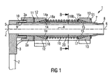
- a first exemplary embodiment of a spring and damping device according to the invention, which is integrated in a tensioning device 1, is in the Fig. 1 to 4 shown.
- the clamping device 1 comprises two clamping arms 2, 3, to each of which at a free end a tensioning roller 22, 23 is arranged freely rotatable.
- the clamping or lever arm 2 has at the opposite end of the tensioning roller 23 an eye 2 a, in which a through hole is introduced.
- the other clamping arm 3 also has on the associated tension roller 22 opposite free end an eye 3a, in which also a through hole is present.
- This through hole is stepped, so that a larger diameter hole and a smaller diameter hole, as in the Fig. 1 can be seen, in the eye 3a is present.
- rotation spring means 4 for example, a torsion bar, rotatably pressed.
- the clamping arm 3 and the claimed torsion spring means 4 may be rotatably connected to each other by positive engagement or by form and frictional engagement.
- a Dahlnutprofil in the end region 5 and a corresponding counter-profile in the eye 3a of the clamping lever 3 for non-rotatable connection of the two elements 3, 4 conceivable.
- the stressed on torsion spring 4 is elongated and has a further free Federend Scheme 6.
- This spring end region 6 is rotatably connected to a hollow cylinder 7.
- the hollow cylinder 7 has a compressed cylinder end 8 which frictionally engages the spring end region 6 of the spring means 4 embraces. Under certain circumstances, a frictional and / or positive connection can also be carried out.
- the claimed torsion spring means 4 is rotatably connected to the cylinder end 8 of the hollow cylinder 7.
- the hollow cylinder 7 is pushed over the spring means 4, so that the spring means is at least largely accommodated in the interior of the hollow cylinder 7, which allows a compact design.
- the other cylinder end 9 of the hollow cylinder 7 extends into the stepped bore in the eye 3a of the clamping arm 3.
- the clamping or lever arm 3 is rotatably mounted on the hollow cylinder 7.
- the cylinder end 9 of the hollow cylinder 7 is turned off by a certain amount on the outer circumference, so that a socket 10 is properly to take care of it and a perfect sliding fit of the sleeve 10 and the clamping arm 3 is ensured.
- the eye sits 2a of the clamping arm 2 also on the hollow cylinder 7 in the region of the cylinder end 9.
- the eye 2a has for this purpose an outside stepped bore in which the eye 3a of the clamping arm 3 is partially inserted.
- the eye 2a of the clamping arm 2 is rotatably mounted on the hollow cylinder 7, for example by pressing. Again, of course, a positive connection between the two elements 2, 7 are provided.
- clamping arm 2 and the clamping arm 3 are resiliently coupled about the common axis of rotation Z by means of the spring means 4 with respect to a pivoting movement of one of the clamping arms 2, 3.
- the suspension is softer or harder.
- the spring stiffness can by appropriate choice of material or dimensioning of the spring means 4 to the respective intended use of the clamping device. 1 be adjusted. A compact design is still achievable. In particular, the diameter of such a spring coupling is low. An extremely cost-effective and effective measure for determining the spring stiffness of the spring means 4 is not to perform the spring means 4 as known per se Torsionsfederstab, but build up of stacked leaf springs 4a, 4b, 4c.
- the spring means 4 consists of three superimposed leaf springs 4a, 4b, 4c, rubbing relative to each other about the rotation axis 6 at a rotation of the clamping arms 2, 3 and thus not only a suspension but also a damping of the relative rotational movement of the two clamping arms makes each other.
- Fig. 1 are between the cylinder end 8 and the cylinder end 9 on the hollow cylinder 7 two plastic cones 14, 15 spaced on the outer circumference of the hollow cylinder 7 from each other.
- the cones 14, 15 are arranged non-rotatably on the hollow cylinder 7, but in the longitudinal direction, that is displaceable in the direction of the axis of rotation Z.
- one or more longitudinal grooves may be formed or milled on the outer circumference of the hollow cylinder 7, in which corresponding springs fit on the inner peripheries of the plastic cones 14, 15.
- the two plastic cones 14, 15 each have conical surfaces which, as in the Fig. 1 shown, facing away from each other.
- the conical surfaces of the plastic cones 14, 15 facing away from end faces 14a, 15a receiving seats for each support ring 16, 17 are provided, on which press the ends 18a, 18b of a coil spring designed as a compression spring 18.
- the compression spring 18 By the compression spring 18, the plastic cones 14, 15 from each other pushed away.
- the cones 14, 15 are guided in the groove profiles, that is, along the axis of rotation Z.
- On the conical surfaces of the plastic cones 14, 15 sit respectively shaped friction elements 12, 13, which have corresponding conical inner holes.
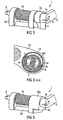
- the friction elements 12, 13 are formed as part of a holder 20, which in particular from the perspective view according to the Fig.
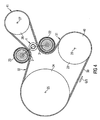
- This first exemplary embodiment of the invention can, as in the Fig. 4 shown to be arranged outside of a belt drive.
- the Indian Fig. 4 The belt drive shown comprises a belt 30, which wraps around a pulley 24 of an internal combustion engine, which sits on the crankshaft 25. Further, the belt drive connects an air conditioning compressor 40 present, which has a rotation axis 29, on which a pulley 28 is seated. The pulley 28 is also looped by the belt 30. Finally, a starter generator 41 is present, which comprises a pulley 26 which sits on a rotation axis 27 of the starter generator 41. Also, this pulley 26 is looped by the belt 30. Outside, in the Fig. 4 "obliquely above" the axis of rotation 27 of the starter generator 41, the axis of rotation Z of the clamping device 1 is arranged. The clamping arms 2, 3 and the respective associated tension rollers 22, 23 touch the belt 30 from the outside.
- the motor drives the belt 30 - the pulley 24 is the traction sheave and the pulley 26 of the starter generator 41, the electrical supply is ensured.
- the tensioning roller 23 is now looped around by the belt 30 over a larger disk circumference, whereas the tensioning roller 23 of the tensioning arm 3 is virtually not wrapped around.
- the vibrations occurring during operation which can be felt in rotational movements of the clamping arms 2, 3, are cushioned by the spring means 4 and both by the internal friction in the claimed torsion spring means 4 and by the separate damping device with the plastic cones 14, 15th , the intermediate coil spring 18 and the friction elements 12, 13 damped.
- FIG Fig. 5 Another exemplary embodiment of the invention is shown in FIG Fig. 5 shown. This corresponds to the tension arm 2 in the Fig. 2 shown embodiment.
- a support 50 is present, which has an eye 50a, in which the hollow cylinder 7 is pressed in non-rotatably.
- the support 50 is like the holder 20 fixedly mounted on a housing or vehicle part.
- the housing of the starter generator 41 can be provided for fastening the holder 20 and the support.
- the support 50 could also be formed integrally with the holder 20.
Landscapes
- Engineering & Computer Science (AREA)
- General Engineering & Computer Science (AREA)
- Mechanical Engineering (AREA)
- Devices For Conveying Motion By Means Of Endless Flexible Members (AREA)
Description
Die vorliegende Erfindung betrifft eine Feder- und Dämpfungsvorrichtung zum Federn Dämpfen der Dreh- bzw. Schwenkbewegung von zumindest einem dreh- bzw. schwenkbar und federnd gelagerten Hebelarm. Insbesondere betrifft die Erfindung eine Feder- und Dämpfungsvorrichtung, die in einer Spannvorrichtung für ein Zugmittel wie beispielsweise ein Riemen oder Kette integriert ist.The present invention relates to a spring and damping device for damping springs of the rotary or pivoting movement of at least one rotatable or pivotable and resiliently mounted lever arm. In particular, the invention relates to a spring and damping device which is integrated in a tensioning device for a traction means such as a belt or chain.
Eine Feder- und Dämpfungsvorrichtung der zuvor genannten Art kann in verschiedensten Anordnungen oder Systemen verwendet werden, in denen eine Drehbewegung zum einen gefedert, zum anderen gedämpft werden soll. Beispielsweise ist eine solche Feder- und Dämpfungsvorrichtung in einer Spannvorrichtung für ein Zugmittel eines Zugmitteltriebs verwendbar, in der die Schwenkbewegung von zumindest einem Spannarm mit Spannmittel, beispielsweise eine Spannrolle, zum Spannen eines Trums des Zugmittels abgefedert und auch gedämpft werden muss.A spring and damping device of the aforementioned type can be used in a variety of arrangements or systems in which a rotational movement to one spring, to be attenuated to the other. For example, such a spring and damping device can be used in a tensioning device for a traction mechanism of a traction mechanism in which the pivoting movement of at least one tensioning arm with tensioning means, for example a tensioning pulley, has to be cushioned and also damped for tensioning a run of the traction means.
Ein besonderes Anwendungsgebiet ist dort zu sehen, wo es in einem Zugmittel- oder Riementrieb zu einem Wechsel zwischen Zugtrum und Leertrum kommt. Ein solcher Trumwechsel erfolgt beispielsweise in einem Riementrieb, der einen Startergenerator und eine Kurbelwelle eines Motors umfasst. Ein solcher Riementrieb wird in einem Startbetrieb und einem Generatorbetrieb betrieben. Je nach Betriebsmodus ist ein Trum ein Zug- oder Leertrum. Somit muss die Spannung des Riemens je nach Betriebsmodus an unterschiedlichen Trums eingestellt werden. Es ist nebenbei anzumerken, dass ein Trum denjenigen Teil des Zugmittels bezeichnet, der zwischen zwei einander benachbarten Umlenkrollen liegt. Die Umlenkrollen, insbesondere Riemenscheiben, können, müssen aber nicht mit Aggregaten zu deren Antrieb verbunden sein.A special field of application is to be seen where, in a traction mechanism or belt drive, a change occurs between the traction strand and the slack side. Such a Trumwechsel takes place for example in a belt drive, which includes a starter generator and a crankshaft of an engine. Such a belt drive is operated in a starting mode and a generator mode. Depending on the operating mode, a strand is a trailing or empty strand. Thus, the tension of the belt must be adjusted depending on the operating mode at different runs. Incidentally, it should be noted that a strand indicates that part of the traction means which lies between two adjacent deflection rollers. The pulleys, in particular Pulleys, but may not be connected to aggregates to their drive.
Bei Verbrennungsmotoren werden Drehbewegungen der Kurbelwelle auf den Riementrieb übertragen. Wie allgemein bekannt, sind die Kurbelwellenumdrehungen allerdings Ungleichförmigkeiten unterworfen, die bei hohen Leistungen und niedrigen Kurbelwellendrehzahlen unter Umständen besonders auffällig sind. Die Folge dieser Drehungleichförmigkeiten sind Wechseldrehmomente, die auf den Riementrieb übertragen werden und dort Beschleunigungen bzw. Verzögerungen im Zugmittel hervorrufen. Derartige Verzögerungen bzw. Beschleunigungen werden dann auch auf Nebenaggregate übertragen, die über den Riementrieb angetrieben werden. Häufig besteht jedoch die Forderung, dass die Nebenaggregate mit möglichst gleichförmigen Drehzahlen arbeiten.In internal combustion engines, rotational movements of the crankshaft are transmitted to the belt drive. However, as is well known, the crankshaft revolutions are subject to nonuniformities that may be particularly noticeable at high powers and low crankshaft speeds. The consequence of these rotational irregularities are alternating torques which are transmitted to the belt drive and cause acceleration or deceleration in the traction means there. Such delays or accelerations are then also transferred to ancillary units, which are driven by the belt drive. Frequently, however, there is the requirement that the ancillaries work with the most uniform speeds possible.
So ist es beispielsweise bei einem Riementrieb der zuvor erläuterten Art möglich, dass ein Motor und ein Startergenerator durch einen einzigen Riemen miteinander gekoppelt sind. Im sogenannten Starterbetrieb treibt der Starter den Motor an. Im sogenannten Generatorbetrieb treibt hingegen der Motor den Startergenerator an, was gegenüber dem Starterbetrieb mit einer Drehmoment einhergeht. Damit ist in einem derartigen Riementrieb einmal ein Trum ein Leertrum oder ein Lasttrum. In einem solchen Riementrieb können auch noch weitere Nebenaggregate integriert sein. Ein Beispiel eines solchen Riementriebs mit Spannvorrichtung ist in der
In der
Die
In der
Eine Riemenspanneinrichtung mit lamellenförmigem Gleitlagerring ist aus der
Auch die
Des Weiteren ist aus der
Schließlich ist noch die gattungsgemäße
Das der Erfindung zugrunde liegende technische Problem besteht darin, eine Feder-und Dämpfungsvorrichtung bereitzustellen, die in kompakter Bauweise und technisch einfach und kostengünstig eine Dreh- bzw. Schwenkbewegung federt und dämpft.The technical problem underlying the invention is to provide a spring and damping device that springs in a compact design and technically simple and cost-effective rotational and pivotal movement and dampens.
Gemäß einem Aspekt der vorliegenden Erfindung wird zur Lösung dieses technischen Problems eine Feder- und Dämpfungsvorrichtung zum Federn und Dämpfen der Dreh- bzw. Schwenkbewegung von zumindest einem dreh- bzw. schwenkbar und federnd gelagerten Hebelarm offenbart. Die erfindungsgemäße Feder- und Dämpfungsvorrichtung umfasst einen ersten Hebelarm, der um eine Drehachse dreh- bzw. schwenkbar gelagert ist. Es ist des Weiteren ein sich längs der Drehachse erstreckendes, auf Verdrehung beanspruchtes Federmittel vorgesehen, das zwei voneinander beabstandete Federendbereiche aufweist, von denen ein erster Federendbereich drehfest mit dem ersten Hebelarm verbunden ist. Es ist ein Hohlzylinder vorhanden, in dessen Zylinderinnenraum das auf Verdrehung beanspruchte Federmittel untergebracht ist und das an einem Zylinderendbereich mit dem zweiten Federendbereich des Federmittels drehfest verbunden ist. Zumindest ein Dämpfungselement ist am Hohlzylinder, innen oder außenseitig, drehfest, aber in Richtung der Drehachse verschiebbar angeordnet ist und mit dem zweiten Federendbereich des auf Verdrehung beanspruchten Federmittels drehfest verbunden. Zumindest ein Reibelement steht zur Dämpfung einer Drehbewegung mit dem Dämpfungselement in Reibkontakt. Eine Feder drückt gegen das zumindest eine Dämpfungselement und bewirkt damit ein vorbestimmtes Reibmoment zwischen dem Dämpfungselement und dem Reibelement zur Dämpfung der Drehbewegung.According to one aspect of the present invention, to solve this technical problem, a spring and damper device for springing and damping the rotational movement of at least one pivotally and resiliently mounted lever arm is disclosed. The spring and damping device according to the invention comprises a first lever arm which is rotatably mounted or pivotable about a rotation axis. There is further provided a longitudinally extending axis of rotation, claimed to torsion spring means having two spaced-apart Federendbereiche, of which a first Federendbereich is rotatably connected to the first lever arm. There is a hollow cylinder present in the cylinder interior, the torsion-stressed spring means is housed and which is rotatably connected at a Zylinderendbereich with the second Federendbereich of the spring means. At least one damping element is on the hollow cylinder, inside or outside, rotationally fixed, but slidably disposed in the direction of the axis of rotation and with the second Federendbereich the claimed on torsion spring means rotatably connected. At least one friction element is for damping a rotational movement with the damping element in frictional contact. A spring presses against the at least one damping element and thus causes a predetermined friction torque between the damping element and the friction element for damping the rotational movement.
Anzumerken ist, dass unter dem Begriff Federendbereich insbesondere derjenige Bereich des auf Verdrehung beanspruchten Federmittels zu verstehen ist, der nicht den eigentlichen Beitrag der Torsionsfederung liefert.It should be noted that the term spring end region is to be understood, in particular, as that region of the spring means subjected to torsion, which does not provide the actual contribution of the torsion suspension.
Der Erfindung liegt der grundsätzliche Gedanke zugrunde, erstmals ein sehr kompakt bauendes und insbesondere einen kleinen Durchmesser aufweisendes, auf Verdrehung beanspruchtes Federmittel als Federung des zumindest einen Hebelarmes vorzusehen und diesem Federmittel eine Dämpfung nachzuschalten. Durch diese Ausgestaltung kann eine Feder- und Dämpfungsvorrichtung mit geringem Durchmesser und kompakter Form erzielt werden. Auch der technische Aufwand ist gering, wodurch die Herstellungskosten reduziert werden.The invention is based on the fundamental idea, for the first time a very compact construction and in particular a small diameter exhibiting, claimed on torsion spring means to provide suspension of at least one lever arm and nachzuschalten this spring means a damping. By this configuration, a spring and damping device can be achieved with a small diameter and a compact shape. The technical complexity is low, whereby the manufacturing cost can be reduced.
In einer beispielhaften Ausführungsform der vorliegenden Erfindung wird das zumindest eine Reibelement mittels einer Feder gegen das Dämpfungselement gedrückt. Damit ist über die Feder das Reibmoment und damit der Dämpfungswert einstellbar. Das Dämpfungselement kann beispielsweise eine drehfest mit dem Federmittel verbundene Scheibe sein, auf deren Seitenflächen ein oder mehrere Reibelemente einwirken, ähnlich einer Scheibenbremse.In an exemplary embodiment of the present invention, the at least one friction element is pressed against the damping element by means of a spring. Thus, the friction torque and thus the damping value can be adjusted via the spring. The damping element may for example be a non-rotatably connected to the spring means disc, acting on the side surfaces of one or more friction elements, similar to a disc brake.
Für eine beispielhafte Anwendung ist es unter Umständen zweckmäßig, das Reibelement beispielsweise als Teil einer Halterung vorzusehen, in der der Hohlzylinder drehbar gelagert ist. Bei letzterer beispielhafter Ausführungsform der vorliegenden Erfindung erfolgt eine Reibwirkung zwischen dem auf dem Hohlzylinder verschiebbar aber drehfest angebrachten Dämpfungselement und einem Teil der Halterung des Hohlzylinders. Die Feder stützt sich hier gegen ein auf dem Hohlzylinder fest angebrachtes Stützelement oder gegen ein anderes Teil der Halterung ab.For an exemplary application, it may be expedient to provide the friction element, for example, as part of a holder in which the hollow cylinder is rotatably mounted. In the latter exemplary embodiment of the present invention, a frictional action between the displaceable on the hollow cylinder but rotatably mounted damping element and a Part of the holder of the hollow cylinder. The spring is supported here against a fixedly mounted on the hollow cylinder support member or against another part of the holder.
Zur Erhöhung der Dämpfung ist bei einer weiteren beispielhaften Ausführungsform der vorliegenden Erfindung ein Hohlzylinder vorhanden, in dessen Innenraum die das auf Verdrehung beanspruchte Federmittel untergebracht ist. An einem Zylinderendbereich ist der Hohlzylinder mit dem zweiten Federendbereich des Federmittels drehfest verbunden. Es sind nunmehr zwei Dämpfungselemente auf dem Hohlzylinder drehfest, aber in Richtung der Drehachse verschiebbar angeordnet. Zwischen den beiden Dämpfungselementen ist eine Feder angeordnet, die die zwei Dämpfungselemente voneinander weg, gegen jeweils ein Reibelement drückt und damit ein vorbestimmtes Reibmoment zwischen jeweils einem Dämpfungselement und einem Reibelement bewirkt. Die Reibelemente können jeweils Teil einer Halterung für den Hohlzylindersein. Beispielsweise können die Teile der Halterung, die als Reibelemente wirken, die einander zugewandten Innenseiten einer Art Gabel mit Durchgangsbohrungen zur Aufnahme des Hohlzylinders sein.To increase the damping in a further exemplary embodiment of the present invention, a hollow cylinder is present in the interior of which the torsion-stressed spring means is housed. At a Zylinderendbereich the hollow cylinder is rotatably connected to the second Federendbereich of the spring means. There are now two damping elements on the hollow cylinder against rotation, but slidably disposed in the direction of the axis of rotation. Between the two damping elements, a spring is arranged, which presses the two damping elements away from each other, each against a friction element and thus causes a predetermined friction between each of a damping element and a friction element. The friction elements may each be part of a holder for the hollow cylinder. For example, the parts of the holder, which act as friction elements, the facing inner sides of a kind of fork with through holes for receiving the hollow cylinder.
Um eine größtmögliche Ausnutzung des begrenzten Bauraums zu erzielen, weisen die Dämpfungselemente jeweils eine Kegelmantelfläche als Reibfläche auf, die jeweils mit entsprechend geformten Reibflächen der Reibelemente in Reibkontakt sind. Damit lassen sich die Reibflächen vergrößern und damit die Dämpfung erhöhen.In order to achieve maximum utilization of the limited space, the damping elements each have a conical surface as a friction surface, which are each in frictional contact with correspondingly shaped friction surfaces of the friction elements. Thus, the friction surfaces can be increased and thus increase the damping.
Eine weitere beispielhafte Ausführungsform sieht vor, dass ein zweiter Hebelarm vorhanden ist, der wie der erste Hebelarm um die Drehachse drehbar gelagert ist. Hervorzuheben ist, dass auch der zweite Hebel um die gleiche Drehachse wie der erste Hebelarm drehbar ist. Der zweite Hebelarm ist aber dann mit dem Dämpfungselement drehfest verbunden, also beispielweise mit einem Zylinderendbereich des zuvor erwähnten Hohlzylinders. Damit ist es möglich, die zwei Hebel auf der gleichen Seite des Federmittels anzuordnen, die beiden Hebel aber über das Federmittel und den Hohlzylinder federnd zu verbinden.A further exemplary embodiment provides that a second lever arm is provided which, like the first lever arm, is rotatably mounted about the axis of rotation. It should be emphasized that the second lever is also rotatable about the same axis of rotation as the first lever arm. But the second lever arm is then rotatably connected to the damping element, so for example with a cylinder end of the aforementioned hollow cylinder. This makes it possible for the To arrange two levers on the same side of the spring means, but to connect the two levers resiliently via the spring means and the hollow cylinder.
Eine beispielhafte Ausführungsform der vorliegenden Erfindung sieht vor, dass die Torsionsfeder ein auf Verdrehung beanspruchtes Federmittel ist. Um insbesondere die Dämpfung noch zu erhöhen, ist in einer weiteren beispielhaften Ausführungsform das auf Verdrehung beanspruchte Federmittel aus einer oder mehreren Blattfedern aufgebaut. Im Falle mehrerer Blattfedern, die auch als Blattfederpaket bezeichnet werden können, reiben die aneinanderliegende Seiten der Blattfedern bei einer Verdrehung aneinander und federn damit die Drehbewegung nicht nur, sondern dämpfen diese auch gleichzeitig.An exemplary embodiment of the present invention provides that the torsion spring is a torsionally stressed spring means. In order to increase the damping even more, in a further exemplary embodiment, the claimed torsion spring means of one or more leaf springs constructed. In the case of a plurality of leaf springs, which can also be referred to as a leaf spring package, the adjacent sides of the leaf springs rub against each other during a rotation and thus not only cushion the rotational movement, but also damp it at the same time.
Bei jeder der zuvor genannten beispielhaften Ausführungsformen kann es zweckmäßig sein, das mit dem Federmittel drehfest verbundene Dämpfungselement, insbesondere der Hohlzylinder in einer Halterung drehbar zu lagern. Bei einer beispielhaften Ausführungsform mit einer solchen Halterung kann vorgesehen sein, dass das oder die Dämpfungselemente in der Halterung integriert sind. Beispielsweise können die Halterung als auch die Dämpfungselemente aus Aluminium- oder Stahlguss bestehen. Die Dämpfungselemente könnten auch in die Halterung eingesetzte Buchse aus einem geeigneten Material sein, beispielsweise Kunststoffbuchsen.In each of the aforementioned exemplary embodiments, it may be expedient to rotatably support the damping element, in particular the hollow cylinder, which is connected in a rotationally fixed manner to the spring means in a holder. In an exemplary embodiment with such a holder can be provided that the one or more damping elements are integrated in the holder. For example, the holder and the damping elements made of aluminum or cast steel. The damping elements could also be used in the holder socket made of a suitable material, such as plastic bushings.
Für eine Spannvorrichtung eines Riementriebs kann bei einer beispielhaften Ausführungsform der vorliegenden Erfindung ein Hebelarm oder beide Hebelarme als Spannarm mit daran angeordnetem Spannmittel ausgebildet sein. Als Spannmittel kommen insbesondere Spannrollen zum Einsatz.For a tensioning device of a belt drive, in an exemplary embodiment of the present invention, a lever arm or both lever arms may be formed as a tensioning arm with tensioning means arranged thereon. As clamping means in particular tension rollers are used.
Eine Spannvorrichtung mit der Feder- und Dämpfungsvorrichtung nach einem der voranstehenden Ausführungsbeispiele kann außerhalb der Innenfläche, die von einem Riemen umschlossen wird, angeordnet sein, so dass die Spannmittel von Außen auf den Riemen angedrückt werden, wobei dann die Drehachse der Spannhebel innerhalb oder außerhalb der vom Riemen umschlossenen Innenfläche liegen kann.A tensioning device with the spring and damping device according to one of the preceding embodiments, outside the inner surface, which is enclosed by a belt, be arranged, so that the clamping means of Pressed externally on the belt, in which case the axis of rotation of the clamping lever can lie inside or outside the belt-enclosed inner surface.
Eine weitere beispielhafte Ausführungsform sieht vor, dass die Feder- und Dämpfungsvorrichtung bzw. Spannvorrichtung nach einem der voranstehenden Ausfiihrungsbeispiele für einen Zugmitteltrieb vorgesehen ist, der den Antrieb eines Startergenerators und möglicherweise weiterer Aggregate einschließt. Das Zugmittel, ein Riemen, umschlingt bzw. verbindet dabei die Riemenscheiben. ein erstes Spannmittel, wie beispielsweise ein Spannarm mit Spannrolle, ist gegen die Außenseite des Trums zwischen der Riemenscheibe des Motors und der Riemenscheibe des Startergenerators spannbar. Ein zweites Spannmittel ist an dem Trum zwischen der Riemenscheibe des Startergenerators und beispielsweise der Riemenscheibe eines weiteren Aggregates spannbar. Die Spannung, wird über das auf Verdrehung beanspruchte Federmittel, insbesondere ein mehrschichtiges Blattfederpaket erzeugt, die Dämpfung über die zuvor erläuterten Dämpfungsmittel und Reibmittel.A further exemplary embodiment provides that the spring and damping device or clamping device is provided according to one of the preceding Ausfiihrungsbeispiele for a traction mechanism, which includes the drive of a starter generator and possibly other aggregates. The traction means, a belt, wraps around or connects the pulleys. a first tensioning means, such as a tensioning arm with tension roller, is tensioned against the outside of the run between the pulley of the motor and the pulley of the starter generator. A second clamping means can be tensioned on the strand between the pulley of the starter generator and, for example, the pulley of a further unit. The tension is generated by the torsion-stressed spring means, in particular a multilayer leaf spring packet, the damping via the previously described damping means and friction means.
Im Folgenden sind zur weiteren Erläuterung und zum besseren Verständnis mehrere beispielhafte Ausführungsformen der vorliegenden Erfindung unter Bezugnahme auf die nachfolgenden Zeichnungen näher beschrieben. Es zeigt:
- Fig. 1
- einen Längsschnitt einer Spannvorrichtung mit einer erfindungsgemäßen Feder- und Dämpfungsvorrichtung, bei der zwei Spannarme über ein auf Verdrehung beanspruchtes Federmittel federnd miteinander gekoppelt sind und deren Dreh- bzw. Schwenkbewegung gedämpft wird;
- Fig. 2
- eine perspektivische Ansicht von schräg oben auf die Spannvorrichtung gemäß der
Fig. 1 ; - Fig. 3
- eine Schnittansicht der Spannvorrichtung mit erfindungsgemäßer Feder- und Dämpfungsvorrichtung entlang der Linie B-B in
Fig. 1 ; - Fig. 4
- eine schematische Seitenansicht auf einen Riementrieb, in den ein Verbrennungsmotor, ein Fahrzeug-Generator als auch ein Starter integriert sind, wobei außerhalb des Riementriebs eine Spannvorrichtung gemäß den
Fig. 1 bis 3 zum korrekten Spannen des Riementriebs, unabhängig von der Laufrichtung des Riemens, angeordnet ist, und - Fig. 5
- eine schematische Seitenansicht einer beispielhaften weiteren Ausführungsform einer Spannvorrichtung mit erfindungsgemäßer Feder- und Dämpfungsvorrichtung mit nur einem Spannarm.
- Fig. 1
- a longitudinal section of a tensioning device with a spring and damping device according to the invention, in which two clamping arms are resiliently coupled to each other via a spring loaded on torsion spring means and whose rotation or pivoting movement is damped;
- Fig. 2
- a perspective view obliquely from above of the clamping device according to the
Fig. 1 ; - Fig. 3
- a sectional view of the clamping device with inventive spring and damping device along the line BB in
Fig. 1 ; - Fig. 4
- a schematic side view of a belt drive, in which an internal combustion engine, a vehicle generator and a starter are integrated, wherein outside the belt drive, a tensioning device according to the
Fig. 1 to 3 for correct tensioning of the belt drive, regardless of the running direction of the belt, is arranged, and - Fig. 5
- a schematic side view of an exemplary further embodiment of a clamping device with inventive spring and damping device with only one clamping arm.
Eine erste beispielhafte Ausführungsform einer erfindungsgemäßen Feder- und Dämpfungsvorrichtung, die in einer Spannvorrichtung 1 integriert ist, ist in den
In der Bohrung mit dem kleineren Durchmesser des Auges 3a des Spannarmes 3 ist ein Federendbereich 5 eines auf Verdrehung beanspruchten Federmittels 4, beispielsweise eine Drehstabfeder, drehfest eingepresst. Selbstverständlich können der Spannarm 3 und das auf Verdrehung beanspruchte Federmittel 4 auch durch Formschluss oder durch Form- und Reibschluss drehfest miteinander verbunden sein. Beispielsweise wäre auch ein Vielnutprofil im Endbereich 5 und ein entsprechendes Gegenprofil im Auge 3a des Spannhebels 3 zur drehfesten Verbindung der zwei Elemente 3, 4 denkbar.In the bore with the smaller diameter of the
Das auf Verdrehung beanspruchte Federmittel 4 ist langgestreckt und weist einen weiteren freien Federendbereich 6 auf. Dieser Federendbereich 6 ist mit einem Hohlzylinder 7 drehfest verbunden. Der Hohlzylinder 7 weist hierzu ein gestauchtes Zylinderende 8 auf, das den Federendbereich 6 des Federmittels 4 reibschlüssig umgreift. Es kann unter Umständen auch eine reib- und/oder formschlüssige Verbindung ausgeführt werden. Damit ist das auf Verdrehung beanspruchte Federmittel 4 mit dem Zylinderende 8 des Hohlzylinders 7 drehfest verbunden.The stressed on
Der Hohlzylinder 7 ist über das Federmittel 4 geschobenen, so dass das Federmittel zumindest größtenteils in dem Inneren des Hohlzylinders 7 aufgenommen ist, was eine kompakte Bauweise ermöglicht. Das andere Zylinderende 9 des Hohlzylinders 7 erstreckt sich bis in die Stufenbohrung im Auge 3a des Spannarmes 3. Dort ist der Spann- bzw. Hebelarm 3 auf dem Hohlzylinder 7 drehbar gelagert. Hierzu ist das Zylinderende 9 des Hohlzylinders 7 um einen gewissen Betrag am Außenumfang abgedreht, so dass eine Buchse 10 einwandfrei darauf aufzupassen ist und ein einwandfreier Gleitsitz der Buchse 10 und des Spannarmes 3 gewährleistet ist.The
Wie insbesondere aus der Schnittdarstellung der
Aus den obigen Ausführungen ist somit zu entnehmen, dass der Spannarm 2 und der Spannarm 3 in Bezug auf eine Dreh- bzw. Schwenkbewegung eines der Spannarme 2, 3 um die gemeinsame Drehachse Z über das Federmittel 4 federnd gekoppelt sind. Je nach Torsionssteifigkeit des langgestreckten bzw. länglichen, auf Verdrehung beanspruchten Federmittels 4 ist die Federung weicher oder härter.It can thus be seen from the above statements that the
Die Federhärte kann durch entsprechende Materialwahl oder Dimensionierung des Federmittels 4 an den jeweiligen Verwendungszweck der Spannvorrichtung 1 angepasst werden. Eine kompakte Bauweise ist dabei weiterhin erzielbar. Insbesondere der Durchmesser einer solchen Federkopplung ist gering. Eine äußerst kostengünstige und effektive Maßnahme zur Festlegung der Federhärte des Federmittels 4 besteht darin, das Federmittel 4 nicht als an sich bekannten Torsionsfederstab auszuführen, sondern aus aufeinandergeschichteten Blattfedern 4a, 4b, 4c aufzubauen.The spring stiffness can by appropriate choice of material or dimensioning of the spring means 4 to the respective intended use of the clamping device. 1 be adjusted. A compact design is still achievable. In particular, the diameter of such a spring coupling is low. An extremely cost-effective and effective measure for determining the spring stiffness of the spring means 4 is not to perform the spring means 4 as known per se Torsionsfederstab, but build up of stacked
Ein entsprechender Aufbau ist insbesondere aus der Schnittansicht aus der
Eine zusätzliche Dämpfung der relativen Drehbewegung der Spannarme 2, 3 wird durch die nachfolgende Dämpfungsanordnung gewährleistet. Gemäß der Schnittansicht der
Die zwei Kunststoffkonen 14, 15 haben jeweils Kegelmantelflächen, die, wie in der
Durch die Kegelmantelflächen wird eine große Reibung erzielt, wodurch eine vorbestimmte Dämpfung der Relativdrehbewegung der Spannarme 2, 3 zusätzlich zu der inneren Reibung des Federmittels 4 erzielbar ist. Durch entsprechende Wahl der Schraubenfeder 18 kann dieser Dämpfwert relativ genau festlegt werden.The two
By the conical surface a large friction is achieved, whereby a predetermined damping of the relative rotational movement of the clamping
Diese erste beispielhafte Ausführungsform der Erfindung kann, wie in der
In dem in
Eine weitere beispielhafte Ausführungsform der Erfindung ist in der
- 11
- Spannvorrichtungjig
- 22
- Spannarmclamping arm
- 2a2a
- SpannarmaugeSpannarmauge
- 33
- Spannarmclamping arm
- 3a3a
- SpannarmaugeSpannarmauge
- 44
- auf Verdrehung beanspruchtes Federmitteltorsion stressed spring means
- 55
- FederendbereichFederendbereich
- 66
- FederendbereichFederendbereich
- 77
- Hohlzylinderhollow cylinder
- 88th
- Zylinderendecylinder end
- 99
- Zylinderendecylinder end
- 1010
- Gleitbuchsebush
- 1111
- Gleitscheibesliding disk
- 1212
- Reibelementfriction
- 1313
- Reibelementfriction
- 1414
- KunststoffkonusPlastic cone
- 1515
- KunststoffkonusPlastic cone
- 1616
- Abstützringsupport ring
- 1717
- Abstützringsupport ring
- 1818
- Druckfedercompression spring
- 18a18a
- DruckfederendeSpring end
- 18b18b
- DruckfederendeSpring end
- 1919
- --
- 2020
- Halterungbracket
- 2121
- --
- 2222
- Spannrolleidler
- 2323
- Spannrolleidler
- 2424
- Riemenscheibepulley
- 2525
- Kurbelwellecrankshaft
- 2626
- Riemenscheibepulley
- 2727
- Drehachse StartergeneratorRotary axis starter generator
- 2828
- Riemenscheibe des KlimakompressorsPulley of air conditioning compressor
- 2929
- Drehachseaxis of rotation
- 3030
- Riemenbelt
- 3131
- Leertrumloose side
- 3232
- LastrumLastrum
- 33-3933-39
- --
- 4040
- Klimakompressorair compressor
- 4141
- Startergeneratorstarter generator
- 42-4942-49
- --
- 5050
- Abstützungsupport
- 50a50a
- Abstützungsaugesupport eye
- 5151
- Sicherungsringcirclip
- ZZ
- Drehachseaxis of rotation
Claims (15)
- Springing and dampening apparatus for springing and dampening of the swivelling motion of at least one lever (2, 3) which lever is swivellingly and springingly mounted with:- a first lever (3) which is pivot-mounted about a pivot axis (Z),- a torsionally stressed springing means (4) extending along the pivot-axis (Z), which springing means comprises two spring end regions (5, 6) spaced apart from one another, whereof a first (5) is torque proof connected to the first lever (3),characterised in that the springing and dampening apparatus comprises- a hollow cylinder (7), in the cylindrical internal space of which the torsionally stressed springing means (4) is housed and which hollow cylinder is torque proof connected at a cylinder end region (8) to the second spring end region (6) of the springing means (4),- at least one dampening element (14, 15) which is torque proof arranged on the hollow cylinder (7), but moveable in direction of the pivot-axis (Z), and which is torque proof connected to the second spring end region (6) of the torsionally stressed springing means (4),- at least one friction element (12, 13), which is in frictional contact with the dampening element (7, 14, 15) for the attenuation of a rotary motion, and- a spring (18), which presses against the at least one dampening element (14, 15) and thus effects a predetermined friction moment between the dampening element (14, 15) and the friction element (12, 13) for the attenuation of the rotary motion.
- Springing and dampening apparatus according to claim 1,
characterised in that- two dampening elements (14, 15) are torque proof arranged on the hollow cylinder (7), but moveable in direction of the pivot-axis (Z), and- the spring (18) is arranged between the two dampening elements (14, 15), wherein the spring (18) presses the two dampening elements (14, 15) away from one another and in each case against a friction element (12, 13) and thus effects a predetermined friction moment between, in each case, a dampening element (14, 15) and a friction element (12, 13). - Springing and dampening apparatus according to one of the preceding claims,
characterised in that the dampening elements (14, 15) in each case comprise a cone superficies surface as a friction surface, which in each case are in frictional contact with correspondingly shaped friction surfaces of the friction elements (12, 13). - Springing and dampening apparatus according to one of the claims 1-4,
characterised in that the at least one friction element (12, 13) is part of a holder (20), in which the hollow cylinder (7) is pivot-mounted. - Springing and dampening apparatus according to one of the preceding claims,
characterised in that a second lever (2) exists, which is pivot-mounted around the pivot-axis (Z) like the first lever (3). - Springing and dampening apparatus according to claim 5,
characterised in that the second lever (2) is torque proof connected to the dampening element (14, 15). - Springing and dampening apparatus according to claim 5 or 6,
characterised in that the second lever (2) is torque proof connected to the hollow cylinder (7). - Springing and dampening apparatus according to one or more of the preceding claims,
characterised in that the springing means (4) comprises one or more leaf springs (4a, 4b, 4c). - Springing and dampening apparatus according to one of the preceding claims,
characterised in that the hollow cylinder (7) which is torque proof connected to the torsionally stressed springing means (4) is pivot-mounted in a holder (12, 13, 20). - Springing and dampening apparatus according to one of the preceding claims,
characterised in that the friction elements (12, 13) are integrated in the holder (20). - Springing and dampening apparatus according to one of the preceding claims,
characterised in that one or both lever are designed as tensioning arms (2, 3) with tensioning means (22, 23) arranged thereon and the tensioning means (2, 3) are designed for the tensioning of a belt (30) in a belt drive. - Springing and dampening apparatus according to claim 11,
characterised in that the belt (30) comprises an inner surface and the springing and dampening apparatus is arranged outside of the inner surface. - Springing and dampening apparatus according to claim 12,
characterised in that the belt (30) is assigned to a traction means drive of a motor, in particular a combustion engine, which comprises the drive of a starter generator (41) and at least one further unit (40) and aggregation (40), respectively. - Springing and dampening apparatus according to claim 13,
characterised in that the belt (30) winds around a belt pulley (24) of the motor, a belt pulley (26) of the starter generator (41) and a belt pulley of the unit (40) and a tensioning means (23) can be tensioned against the strand between the belt pulley (24) of the motor and the belt pulley (26) of the starter generator (41) and a tensioning means (22) can be tensioned against the strand between the belt pulley (28) of the unit (40) and the belt pulley (26) of the starter generator (41). - Springing and dampening apparatus according to claim 13 or 14,
characterised in that the unit is a climate compressor and an air-conditioning compressor (40), respectively.
Applications Claiming Priority (3)
| Application Number | Priority Date | Filing Date | Title |
|---|---|---|---|
| DE2002151859 DE10251859A1 (en) | 2002-11-07 | 2002-11-07 | Spring and damper arrangement for pivotal movement of sprung mounted lever arm(s), e.g. for chain tensioner, has friction element(s) in frictional contact with damping element to damp rotary movement |
| DE10251859 | 2002-11-07 | ||
| PCT/EP2003/012347 WO2004042253A1 (en) | 2002-11-07 | 2003-11-05 | Springing and dampening device |
Publications (2)
| Publication Number | Publication Date |
|---|---|
| EP1558859A1 EP1558859A1 (en) | 2005-08-03 |
| EP1558859B1 true EP1558859B1 (en) | 2008-03-19 |
Family
ID=32115343
Family Applications (1)
| Application Number | Title | Priority Date | Filing Date |
|---|---|---|---|
| EP03810440A Expired - Lifetime EP1558859B1 (en) | 2002-11-07 | 2003-11-05 | Springing and dampening device |
Country Status (4)
| Country | Link |
|---|---|
| EP (1) | EP1558859B1 (en) |
| AU (1) | AU2003276255A1 (en) |
| DE (2) | DE10251859A1 (en) |
| WO (1) | WO2004042253A1 (en) |
Families Citing this family (11)
| Publication number | Priority date | Publication date | Assignee | Title |
|---|---|---|---|---|
| DE10253450A1 (en) * | 2002-11-16 | 2004-05-27 | Bayerische Motoren Werke Ag | Clamping device for an envelope drive of a unit |
| EP1437528B1 (en) * | 2003-01-10 | 2010-03-10 | Muhr und Bender KG | Belt tensioner |
| EP1464871B1 (en) | 2003-04-02 | 2008-05-28 | DAYCO EUROPE S.r.l. | Two-arm belt tensioner |
| DE10336505B4 (en) * | 2003-08-06 | 2006-12-14 | Litens Automotive Gmbh | Circulating drive clamping device for a circulation drive of an internal combustion engine |
| WO2005024271A1 (en) * | 2003-08-06 | 2005-03-17 | Litens Automotive Gmbh | Tensing device for the rotary drive of an internal combustion engine |
| DE102004053209A1 (en) * | 2004-11-04 | 2006-07-13 | Schaeffler Kg | Clamping device for a traction drive with directional damping |
| DE102005029789A1 (en) * | 2005-06-24 | 2006-12-28 | Muhr Und Bender Kg | Belt tensioner with external damping sleeve |
| DE102005029753A1 (en) * | 2005-06-24 | 2006-12-28 | Muhr Und Bender Kg | Belt tensioning device for attachment to an aggregate |
| DE102005053128A1 (en) * | 2005-11-08 | 2007-05-10 | Schaeffler Kg | Tensioning device for traction mechanism comprises stationary base part and clamping lever, which is supported in damped manner over two friction elements e.g. friction ring, which are braced opposite to each other |
| DE102012205146A1 (en) * | 2012-03-29 | 2013-10-02 | Bayerische Motoren Werke Aktiengesellschaft | Belt drive for operatively connecting initiator generator with crankshaft of e.g. petrol engine for motor car, has traction unit wrapped around driving wheels, where force is transferred from one wheel to another wheel in regenerative mode |
| CN118637316B (en) * | 2024-08-15 | 2024-11-12 | 江苏铭瀚智能科技有限公司 | Double cone structure buffer device |
Family Cites Families (11)
| Publication number | Priority date | Publication date | Assignee | Title |
|---|---|---|---|---|
| US1667117A (en) * | 1926-07-15 | 1928-04-24 | Nat Refrigeration Corp | Belt-tightening-idler mount |
| DE2608277A1 (en) * | 1976-02-28 | 1977-09-01 | Porsche Ag | TENSIONING DEVICE FOR BELTS, CHAINS OR THE SAME |
| DE3719794A1 (en) | 1987-06-13 | 1988-12-22 | Skf Gmbh | Pivot bearing |
| DE3912944A1 (en) | 1989-03-15 | 1990-09-20 | Muhr & Bender | Tensioning device for vehicle drive belts - consists of hexagonal sectioned torsion bar, with lever and roller or disc |
| DE4243451A1 (en) | 1992-12-22 | 1994-06-23 | Schaeffler Waelzlager Kg | Tensioner for belt or chain in combustion IC-engine |
| DE4428560A1 (en) | 1994-08-12 | 1996-02-15 | Schaeffler Waelzlager Kg | Tensioning device with lamellar form plane bearing ring |
| DE4431801A1 (en) | 1994-09-07 | 1996-03-14 | Schaeffler Waelzlager Kg | Belt, chain etc tensioner with direction dependent damping |
| IT1277619B1 (en) | 1995-08-04 | 1997-11-11 | Castelgarden Spa | BIDIRECTIONAL ELASTIC CHAIN TENSIONER |
| DE19631507A1 (en) | 1996-08-03 | 1998-02-05 | Bayerische Motoren Werke Ag | Pulley-drive belt tensioning unit in tub-shaped pulley wheel |
| DE19849886A1 (en) | 1998-10-29 | 2000-05-11 | Bosch Gmbh Robert | Belt drive, especially in internal combustion engines for driving auxiliary units of a vehicle |
| DE19926612A1 (en) | 1999-06-11 | 2000-12-14 | Schaeffler Waelzlager Ohg | Belt drive of an internal combustion engine |
-
2002
- 2002-11-07 DE DE2002151859 patent/DE10251859A1/en not_active Withdrawn
-
2003
- 2003-11-05 AU AU2003276255A patent/AU2003276255A1/en not_active Abandoned
- 2003-11-05 EP EP03810440A patent/EP1558859B1/en not_active Expired - Lifetime
- 2003-11-05 WO PCT/EP2003/012347 patent/WO2004042253A1/en not_active Ceased
- 2003-11-05 DE DE50309430T patent/DE50309430D1/en not_active Expired - Lifetime
Also Published As
| Publication number | Publication date |
|---|---|
| AU2003276255A1 (en) | 2004-06-07 |
| WO2004042253A1 (en) | 2004-05-21 |
| DE10251859A1 (en) | 2004-05-19 |
| AU2003276255A8 (en) | 2004-06-07 |
| EP1558859A1 (en) | 2005-08-03 |
| DE50309430D1 (en) | 2008-04-30 |
Similar Documents
| Publication | Publication Date | Title |
|---|---|---|
| DE3512376C2 (en) | ||
| DE3225411C2 (en) | ||
| DE10063638B4 (en) | Automatic self-tensioning device | |
| DE60208576T2 (en) | DAMPING MECHANISM FOR A TENSIONING DEVICE | |
| EP2005028B1 (en) | Tensioning device of a traction mechanism drive | |
| DE69415169T2 (en) | BELT TENSIONER | |
| DE69911662T2 (en) | DRIVEN PULLEY | |
| DE10131916A1 (en) | Tensioning device for traction devices, in particular belt tensioning device | |
| WO2008119594A1 (en) | Tensioning device of a belt and chain drive | |
| DE3590411T (en) | Belt tensioner and manufacturing process | |
| EP2573423A1 (en) | Belt tensioning device for a belt drive and machine arrangement with belt tensioning device | |
| EP1558859B1 (en) | Springing and dampening device | |
| DE4243451A1 (en) | Tensioner for belt or chain in combustion IC-engine | |
| DE102008026064B4 (en) | Belt tensioner arrangement for a belt drive | |
| DE102018215451A1 (en) | Motorcycle with a tensioning device for tensioning a tension member and tensioning device for a motorcycle | |
| EP3505907B1 (en) | Testing device | |
| DE102006041417B3 (en) | Traction drive with a compensation device for vibration reduction | |
| WO2003036130A1 (en) | Tensioning device | |
| DE102004012395B4 (en) | Clamping unit for a unit operation | |
| EP3943778B1 (en) | Belt tensioning device and belt drive comprising such a belt tensioning device | |
| DE3546901C2 (en) | Endless belt tensioner | |
| EP1781913A1 (en) | Centre of rotation support for an assembly | |
| DE102022100471B4 (en) | Belt drive for driving a motor vehicle, in particular a motorcycle, and motor vehicle, in particular a motorcycle | |
| DE102016103197A1 (en) | BELT TRANSMISSION AND STEERING SYSTEM | |
| DE102004006907A1 (en) | Tensioning system for power transmission drive in e.g. motor vehicle, includes tensioning part with opposite ends connected to lever arm and force transducer |
Legal Events
| Date | Code | Title | Description |
|---|---|---|---|
| PUAI | Public reference made under article 153(3) epc to a published international application that has entered the european phase |
Free format text: ORIGINAL CODE: 0009012 |
|
| 17P | Request for examination filed |
Effective date: 20050502 |
|
| AK | Designated contracting states |
Kind code of ref document: A1 Designated state(s): AT BE BG CH CY CZ DE DK EE ES FI FR GB GR HU IE IT LI LU MC NL PT RO SE SI SK TR |
|
| AX | Request for extension of the european patent |
Extension state: AL LT LV MK |
|
| DAX | Request for extension of the european patent (deleted) | ||
| RBV | Designated contracting states (corrected) |
Designated state(s): DE FR GB IT |
|
| RAP1 | Party data changed (applicant data changed or rights of an application transferred) |
Owner name: CONTITECH ANTRIEBSSYSTEME GMBH Owner name: SCHAEFFLER KG |
|
| GRAP | Despatch of communication of intention to grant a patent |
Free format text: ORIGINAL CODE: EPIDOSNIGR1 |
|
| GRAS | Grant fee paid |
Free format text: ORIGINAL CODE: EPIDOSNIGR3 |
|
| GRAA | (expected) grant |
Free format text: ORIGINAL CODE: 0009210 |
|
| AK | Designated contracting states |
Kind code of ref document: B1 Designated state(s): DE FR GB IT |
|
| REG | Reference to a national code |
Ref country code: GB Ref legal event code: FG4D Free format text: NOT ENGLISH |
|
| REF | Corresponds to: |
Ref document number: 50309430 Country of ref document: DE Date of ref document: 20080430 Kind code of ref document: P |
|
| ET | Fr: translation filed | ||
| PLBE | No opposition filed within time limit |
Free format text: ORIGINAL CODE: 0009261 |
|
| STAA | Information on the status of an ep patent application or granted ep patent |
Free format text: STATUS: NO OPPOSITION FILED WITHIN TIME LIMIT |
|
| 26N | No opposition filed |
Effective date: 20081222 |
|
| PG25 | Lapsed in a contracting state [announced via postgrant information from national office to epo] |
Ref country code: IT Free format text: LAPSE BECAUSE OF FAILURE TO SUBMIT A TRANSLATION OF THE DESCRIPTION OR TO PAY THE FEE WITHIN THE PRESCRIBED TIME-LIMIT Effective date: 20080319 |
|
| REG | Reference to a national code |
Ref country code: GB Ref legal event code: 732E Free format text: REGISTERED BETWEEN 20110106 AND 20110112 |
|
| PGFP | Annual fee paid to national office [announced via postgrant information from national office to epo] |
Ref country code: GB Payment date: 20101130 Year of fee payment: 8 |
|
| PGFP | Annual fee paid to national office [announced via postgrant information from national office to epo] |
Ref country code: FR Payment date: 20111214 Year of fee payment: 9 |
|
| REG | Reference to a national code |
Ref country code: FR Ref legal event code: TP Owner name: CONTI'TECH ANTRIEBSSYSTEME GMBH, DE Effective date: 20120127 |
|
| PGFP | Annual fee paid to national office [announced via postgrant information from national office to epo] |
Ref country code: DE Payment date: 20120131 Year of fee payment: 9 |
|
| REG | Reference to a national code |
Ref country code: DE Ref legal event code: R082 Ref document number: 50309430 Country of ref document: DE Representative=s name: MAIWALD PATENTANWALTSGESELLSCHAFT MBH, DE |
|
| REG | Reference to a national code |
Ref country code: DE Ref legal event code: R082 Ref document number: 50309430 Country of ref document: DE Representative=s name: MAIWALD PATENTANWALTSGESELLSCHAFT MBH, DE Effective date: 20120828 Ref country code: DE Ref legal event code: R081 Ref document number: 50309430 Country of ref document: DE Owner name: SCHAEFFLER TECHNOLOGIES AG & CO. KG, DE Free format text: FORMER OWNER: SCHAEFFLER TECHNOLOGIES GMBH & CO. KG, 91074 HERZOGENAURACH, DE Effective date: 20120828 |
|
| GBPC | Gb: european patent ceased through non-payment of renewal fee |
Effective date: 20121105 |
|
| REG | Reference to a national code |
Ref country code: FR Ref legal event code: ST Effective date: 20130731 |
|
| REG | Reference to a national code |
Ref country code: DE Ref legal event code: R119 Ref document number: 50309430 Country of ref document: DE Effective date: 20130601 |
|
| PG25 | Lapsed in a contracting state [announced via postgrant information from national office to epo] |
Ref country code: DE Free format text: LAPSE BECAUSE OF NON-PAYMENT OF DUE FEES Effective date: 20130601 |
|
| PG25 | Lapsed in a contracting state [announced via postgrant information from national office to epo] |
Ref country code: GB Free format text: LAPSE BECAUSE OF NON-PAYMENT OF DUE FEES Effective date: 20121105 Ref country code: FR Free format text: LAPSE BECAUSE OF NON-PAYMENT OF DUE FEES Effective date: 20121130 |